1
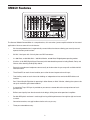
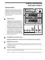
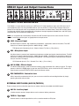
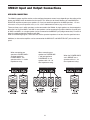
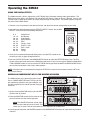
GI
2
DI 4
EC
FF
TA
L
T
I
B
D
E S
P
TS
SIX CHANNEL POWERED MIXER
WITH 24BIT DIGITAL EFFECTS
Powered Mixers
XM610
Safety Instructions/Consignes de sécurité/Sicherheitsvorkehrungen/Instrucciones de seguridad
WARNING: To reduce the risk of fire or electric shock, do not expose this unit to
rain or moisture. To reduce the hazard of electrical shock, do not remove cover or
back. No user serviceable parts inside. Please refer all servicing to qualified personnel.The lightning flash with an arrowhead symbol within an equilateral triangle,
is intended to alert the user to the presence of uninsulated "dangerous voltage"
within the products enclosure that may be of sufficient magnitude to constitute a
risk of electric shock to persons. The exclamation point within an equilateral triangle is intended to alert the user to the presence of important operating and maintenance (servicing) instructions in the literature accompanying the product.
Important Safety Instructions
1. Please read all instructions before operating the unit.
2. Keep these instructions for future reference.
3. Please heed all safety warnings.
4. Follow manufacturers instructions.
5. Do not use this unit near water or moisture.
6. Clean only with a damp cloth.
7. Do not block any of the ventilation openings. Install in accordance with the
manufacturers instructions.
8. Do not install near any heat sources such as radiators, heat registers, stoves,
or other apparatus (including amplifiers) that produce heat.
9. Do not defeat the safety purpose of the polarized or grounding-type plug. A
polarized plug has two blades with one wider than the other. A grounding type
plug has two blades and a third grounding prong. The wide blade or third
prong is provided for your safety. When the provided plug does not fit your
outlet, consult an electrician for replacement of the obsolete outlet.
10. Protect the power cord from being walked on and pinched particularly at
plugs, convenience receptacles and at the point at which they exit from the
unit.
11. Unplug this unit during lightning storms or when unused for long periods of
time.
12. Refer all servicing to qualified personnel. Servicing is required when the unit
has been damaged in any way, such as power supply cord or plug damage, or
if liquid has been spilled or objects have fallen into the unit, the unit has been
exposed to rain or moisture, does not operate normally, or has been dropped.
ATTENTION: Pour éviter tout risque d’électrocution ou d’incendie, ne pas
exposer cet appareil à la pluie ou à l’humidité. Pour éviter tout risque d’électrocution, ne pas ôter le couvercle ou le dos du boîtier. Cet appareil ne contient aucune
pièce remplaçable par l'utilisateur. Confiez toutes les réparations à un personnel qualifié. Le signe avec un éclair dans un triangle prévient l’utilisateur de la
présence d’une tension dangereuse et non isolée dans l’appareil. Cette tension
constitue un risque d’électrocution. Le signe avec un point d’exclamation dans
un triangle prévient l’utilisateur d’instructions importantes relatives à l’utilisation
et à la maintenance du produit.
Consignes de sécurité importantes
1. Veuillez lire toutes les instructions avant d’utiliser l’appareil.
2. Conserver ces instructions pour toute lecture ultérieure.
3. Lisez avec attention toutes les consignes de sécurité.
4. Suivez les instructions du fabricant.
5. Ne pas utiliser cet appareil près d’une source liquide ou dans un lieu
humide.
6. Nettoyez l’appareil uniquement avec un tissu humide.
7. Veillez à ne pas obstruer les fentes prévues pour la ventilation de l’appareil.
Installez l’appareil selon les instructions du fabricant.
8. Ne pas installer près d’une source de chaleur (radiateurs, etc.) ou de tout
équipement susceptible de générer de la chaleur (amplificateurs de puissance par exemple).
9. Ne pas retirer la terre du cordon secteur ou de la prise murale. Les fiches
canadiennes avec polarisation (avec une lame plus large) ne doivent pas
être modifiées. Si votre prise murale ne correspond pas au modèle fourni,
consultez votre électricien.
10. Protégez le cordon secteur contre tous les dommages possibles (pincement, tension, torsion,, etc.). Veillez à ce que le cordon secteur soit libre,
en particulier à sa sortie du boîtier.
11. Déconnectez l’appareil du secteur en présence d’orage ou lors de périodes
d’inutilisation prolongées.
12. Consultez un service de réparation qualifié pour tout dysfonctionnement
(dommage sur le cordon secteur, baisse de performances, exposition à la
pluie, projection liquide dans l’appareil, introduction d’un objet dans le boîtier, etc.).
ACHTUNG: Um die Gefahr eines Brandes oder Stromschlags zu verringern, sollten Sie dieses Gerät weder Regen noch Feuchtigkeit aussetzen.Um die Gefahr
eines Stromschlags zu verringern, sollten Sie weder Deckel noch Rückwand des
Geräts entfernen. Im Innern befinden sich keine Teile, die vom Anwender
gewartet werden können. Überlassen Sie die Wartung qualifiziertem
PRECAUCION: Para reducir el riesgo de incendios o descargas, no permita que
este aparato quede expuesto a la lluvia o la humedad. Para reducir el riesgo de
descarga eléctrica, nunca quite la tapa ni el chasis. Dentro del aparato no hay
piezas susceptibles de ser reparadas por el usuario. Dirija cualquier reparación al
servicio técnico oficial. El símbolo del relámpago dentro del triángulo equilátero
pretende advertir al usuario de la presencia de “voltajes peligrosos” no aislados
dentro de la carcasa del producto, que pueden ser de la magnitud suficiente como
para constituir un riesgo de descarga eléctrica a las personas. El símbolo de exclamación dentro del triángulo equilátero quiere advertirle de la existencia de importantes instrucciones de manejo y mantenimiento (reparaciones) en los documentos
que se adjuntan con este aparato.
Instrucciones importantes de seguridad
1.
Lea todo este manual de instrucciones antes de comenzar a usar la unidad.
2.
Conserve estas instrucciones para cualquier consulta en el futuro.
3.
Cumpla con todo lo indicado en las precauciones de seguridad.
4.
Observe y siga todas las instrucciones del fabricante.
5.
Nunca utilice este aparato cerca del agua o en lugares húmedos.
6.
Limpie este aparato solo con un trapo suave y ligeramente humedecido.
7.
No bloquee ninguna de las aberturas de ventilación. Instale este aparato de
acuerdo a las instrucciones del fabricante.
8.
No instale este aparato cerca de fuentes de calor como radiadores, calentadores, hornos u otros aparatos (incluyendo amplificadores) que produzcan
calor.
9.
No anule el sistema de seguridad del enchufe de tipo polarizado o con toma
de tierra. Un enchufe polarizado tiene dos bornes, uno más ancho que el
otro. Uno con toma de tierra tiene dos bornes normales y un tercero para la
conexión a tierra. El borne ancho o el tercero se incluyen como medida de
seguridad. Cuando el enchufe no encaje en su salida de corriente, llame a un
electricista para que le cambie su salida anticuada.
10. Evite que el cable de corriente quede en una posición en la que pueda ser
pisado o aplastado, especialmente en los enchufes, receptáculos y en el
punto en el que salen de la unidad.
11. Desconecte de la corriente este aparato durante las tormentas eléctricas o
cuando no lo vaya a usar durante un periodo de tiempo largo.
12. Dirija cualquier posible reparación solo al servicio técnico oficial. Deberá
hacer que su aparato sea reparado cuando esté dañado de alguna forma,
como si el cable de corriente o el enchufe están dañados, o si se han derramado líquidos o se ha introducido algún objeto dentro de la unidad, si esta ha
quedado expuesta a la lluvia o la humedad, si no funciona normalmente o si
ha caído al suelo.
Fachpersonal.Der Blitz mit Pfeilspitze im gleichseitigen Dreieck soll den Anwender
vor nichtisolierter “gefährlicher Spannung” im Geräteinnern warnen. Diese
Spannung kann so hoch sein, dass die Gefahr eines Stromschlags besteht. Das
Ausrufezeichen im gleichseitigen Dreieck soll den Anwender auf wichtige
Bedienungs- und Wartungsanleitungen aufmerksam machen, die im mitgelieferten
Informationsmaterial näher beschrieben werden.
Wichtige Sicherheitsvorkehrungen
1. Lesen Sie alle Anleitungen, bevor Sie das Gerät in Betrieb nehmen.
2. Bewahren Sie diese Anleitungen für den späteren Gebrauch gut auf.
3. Bitte treffen Sie alle beschriebenen Sicherheitsvorkehrungen.
4. Befolgen Sie die Anleitungen des Herstellers.
5. Benutzen Sie das Gerät nicht in der Nähe von Wasser oder Feuchtigkeit.
6. Verwenden Sie zur Reinigung des Geräts nur ein feuchtes Tuch.
7. Blockieren Sie keine Belüftungsöffnungen. Nehmen Sie den Einbau des
Geräts nur entsprechend den Anweisungen des Herstellers vor.
8. Bauen Sie das Gerät nicht in der Nähe von Wärmequellen wie Heizkörpern,
Wärmeklappen, Öfen oder anderen Geräten (inklusive Verstärkern) ein, die
Hitze erzeugen.
9. Setzen Sie die Sicherheitsfunktion des polarisierten oder geerdeten Steckers
nicht außer Kraft. Ein polarisierter Stecker hat zwei flache, unterschiedlich breite Pole. Ein geerdeter Stecker hat zwei flache Pole und einen dritten
Erdungsstift. Der breitere Pol oder der dritte Stift dient Ihrer Sicherheit. Wenn
der vorhandene Stecker nicht in Ihre Steckdose passt, lassen Sie die veraltete
Steckdose von einem Elektriker ersetzen.
10. Schützen Sie das Netzkabel dahingehend, dass niemand darüber laufen und
es nicht geknickt werden kann. Achten Sie hierbei besonders auf Netzstecker,
Mehrfachsteckdosen und den Kabelanschluss am Gerät.
11. Ziehen Sie den Netzstecker des Geräts bei Gewittern oder längeren
Betriebspausen aus der Steckdose.
12. Überlassen Sie die Wartung qualifiziertem Fachpersonal. Eine Wartung ist
notwendig, wenn das Gerät auf irgendeine Weise, beispielsweise am Kabel
oder Netzstecker beschädigt wurde, oder wenn Flüssigkeiten oder Objekte in
das Gerät gelangt sind, es Regen oder Feuchtigkeit ausgesetzt war, nicht
mehr wie gewohnt betrieben werden kann oder fallen gelassen wurde.
Table of Contents
Introduction
2
XM610 Features
3
Controls and Functions
Front Panel Layout
Front Panel Controls
4
5–9
XM610 Input and Output Connections
10–12
Operating the XM610
13–15
System Set-ups
16–17
XM610 Wiring Guide
18
Specifications
19
Block Diagram
20
Copyright 2004, Samson Technologies Corp.
Printed March, 2004
Samson Technologies Corp.
575 Underhill Blvd.
P.O. Box 9031
Syosset, NY 11791-9031
Phone: 1-800-3-SAMSON (1-800-372-6766)
Fax: 516-364-3888
www.samsontech.com
XM610 Features
The Samson XM610 Powered Mixer is a comprehensive, all-in-one mixer / power amplifier solution for live sound
applications. Here are some of its main features:
•
Six channel powered mixer in ergonomically correct kickback enclosure allowing you to easily see and
operate the front panel functions.
•
Six Mic / Line inputs with 1/4-inch phone and XLR connectors.
•
2 x 300 Watts, or 300 Watt Main / 300 Watt Monitor, or 600 Watts Bridged power operating modes.
•
A built-in, 24-bit DSP (Digital Signal Processor) with 100 selectable presets including Reverb, Delay and
Chorus, offers dazzling studio quality effects.
•
Dynamic or condenser microphones connect easily to the low noise mic pre-amps with available 48 Volt
Phantom Power.
•
The 3-Band EQ on each channel enables you to tailor the tonal response for each input.
*
Two Auxiliary sends on each channel for building an independent mix to send to the DSP effects and
monitors.
•
Dual 7-band Graphic Equalizer for operating in either Stereo, or Main / Monitor, allowing the system to be
set-up for maximum gain before feedback.
•
A convenient Tape / CD Input is provided so you connect a stereo device for accompaniment or background music.
•
Brilliant sound quality from the advanced circuit design, utilizing low noise operational amplifiers.
•
Durable ABS plastic enclosure is road tough insuring reliable performance from night to night and venue
to venue .
•
Convenient oversize, sure grip handle make the unit easy to carry.
•
Three-year extended warranty.
2
Introduction
Congratulations on your purchase of the Samson XM610 powered mixer! The XM610 is a six
channel, 600 Watt powered mixer with a built-in, 24 BIT DSP (Digital Signal Processor)
effects. The XM610 will give you clean, clear sound reproduction thanks to the high quality,
low noise microphone preamps, super clean mix bus, two on-board 7-band graphic equalizers
and the high output/low distortion power amplifier. For studio quality processing, you can add
one of the 100 dazzling digital effects including Delays, Chorus and lush Reverbs to your voice
or instruments. The XM610’s ingenius Kickback enclosure allows you to tilt the unit back to
see, and operate, the controls with ease. The unit is easy to transport with its compact size
and oversized, sure-grip handle. The super-tough ABS construction ensures reliable, high
quality sound from venue-to-venue and performance-to-performance day in, and night out.
Optimized for live sound reinforcement and commercial installations, the XM610 is an ideal
mixer and power amp solution offering big sound in a compact package.
In these pages, you’ll find a detailed description of the features of the XM610 powered mixer,
as well a description of its front and rear panels, step-by-step instructions for its setup and
use, and full specifications. You’ll also find a warranty card enclosed—please don’t forget to fill
it out and mail it in so that you can receive online technical support and so we can send you
updated information about these and other Samson products in the future.
With proper care and adequate air circulation, your unit will operate trouble free for many
years. We recommend you record your serial number in the space provided below for future
reference.
Serial number:
Date of purchase:
Should your unit ever require servicing, a Return Authorization number (RA) must be obtained
before shipping your unit to Samson. Without this number, the unit will not be accepted.
Please call Samson at 1-800-3SAMSON (1-800-372-6766) for a Return Authorization number
prior to shipping your unit. Please retain the original packing materials and if possible, return
the unit in the original carton and packing materials.
3
Controls and Functions
FRONT PANEL LAYOUT
4
Controls and Functions
FRONT PANEL CONTROLS
INPUT CHANNEL SECTION
The following section details each part of the XM610’s INPUT CHANNELS
including the 3-BAND EQ, the MONITOR and EFX sends, LEVEL and PAD
controls.
1 HIGH MID LOW - Channel Equalizer
The XM610 input channels feature a 3-band equalizer allowing you to
adjust the high, mid, and low frequencies independently on each channel. The channel’s frequency response is flat when the knobs are in the
"12:00" position. Rotating the knob towards the right will boost the corresponding frequency band by 12dB/15dB, and rotating it towards the left
will cut the frequency by 12dB/15dB. The frequency centers, range of
boost or cut, and equalizer type for each band are as follows:
High: 12KHz +/- 15dB shelving type
Mid: 2.5KHz +/- 12dB peaking type
Low: 80Hz +/- 15dB shelving type
2
AUX 1/MON - Monitor Send
2
3
Each of the XM610’s channels include a MONITOR send which controls
the amount of that channel’s signal that is sent to the MONITOR bus.
The Input channel’s MONITOR sends are mixed together and are sent to
the speakers connected to the POWER AMP 1 A/B jacks if the POWER
AMP select switch is set to MAIN+MONITOR.
3
1
4
5
AUX 2 / EFX Effects Send
The XM610 provides high quality, 24 Bit digital effects, and the level of
effects can be set independently on each channel. The channel’s EFX (Effects) knob controls the amount
of signal that is sent to the EFX bus. The signal of the EFX bus is routed to the DSP EFX section for onboard signal processing. The EFX signal can also be sent to an external effect device connected to the
EFX OUT jacks located on the front panel.
NOTE: The channel’s EFX signal is sent to the EFX bus from a location in the signal path after the VOLUME control (4). This is commonly referred as a POST FADER send. This means that the amount of signal that is sent to the EFFECT bus will be affected not only by the setting of the EFX knob control, but it
will also be affected by the setting of the VOLUME control.
4
VOLUME - Level Control
The VOLUME control adjusts the output volume of each channel.
5
PAD - Pad Switch
The PAD switch attenuates the input signal by 20dB. When connecting a hot signal such as a line level
device to channels 1-6, or if the mic input is distorted, turn this switch on (the pressed-in position) and
readjust the VOLUME control.
5
Controls and Functions
FRONT PANEL CONTROLS
24 BIT DIGITAL EFFECT SECTION
The XM610 features a built-in, 24 Bit Digital Effects processor with 100 high
quality, studio grade effects like Delay, Chorus and Reverb. The following section describes the features of the powerful on-board digital effects section.
6 SELECT - Digital Effects Select Switch
The SELECT switch allows you to pick one of the 100 built-in digital effects.
Simply rotate the SELECT to choose the effect.
6
Effect PROGRAM List
This section identifies the ten banks of built-in DSP effects presets. The first
bank of 10 presets are designed for live performance, and the following banks
are set up in groups by the types of effects.
7
7 EFX LEVEL - Master Effect Send
The EFX LEVEL control is used to send the effect mix bus to an external effect
device connected to the AUX 2 SEND jack.
8 EFX ON - switch
The EFX ON control is used to turn the internal Digital Effect on and off. The
effects are by-passed when the switch is in the out position and the display
shows two dashes.
TAPE IN AND AUX IN SECTION
This allows you to adjust the level of the signal from an external device such
as a MP3 , cassette, or CD player or from an external effect device.
9 VOLUME - Tape In Level Control
This adjusts the amount of signal that is sent from the TAPE IN jacks to the
MAIN bus.
10 VOLUME - Aux In Control
9
This adjusts the amount of signal that is sent from the AUX IN jacks to the
MAIN bus.
10
6
8
Controls and Functions
FRONT PANEL CONTROLS
POWER AMP SECTION
The XM610’s power amplifier section can
be configured to operate several ways
depending on whether you need MAIN plus
MONITOR amplifiers to power your speakers, or if you just need more power for the
MAIN speakers. The section below
describes the XM610 power amp modes.
11
Mode - Power amp Mode switch
The MODE switch is used to select one of
three different operating modes, MAINMONITOR, MAIN-MAIN and MAINBRIDGE. The following is a description of
each of the POWER operating modes:
11
CAUTION! Only change the power amp mode switch when the XM610’s power is SWITCHED OFF!
MAIN-MONITOR
With this setting, the MAIN and MONITOR sections can be used independently. The MAIN bus signal will
be sent from the POWER AMP 2 A/B jacks, and the MONITOR bus signal will be sent from the POWER
AMP 1 A/B jacks.
MAIN-MAIN
With this setting, the two power amp channels can be used independently. The MAIN bus signal will be
output from the POWER AMP 1 A/B jacks (Rear Panel), and also, from the POWER AMP 2 A/B jacks
(Rear Panel 1).
MAIN-BRIDGE
With this setting, the two power amp channels (A and B) will be connected in bridge mode. Only the MAIN
bus signal will be output from the BRIDGE jack.
7
Controls and Functions
FRONT PANEL CONTROLS
MAIN SECTION
The XM610 has two internal power amplifiers and
depending on the power amp MODE selection
switch, the amplifiers are sent the MAIN or MONITOR bus signal. The following section describes the
MAIN bus operation, which allows you to adjust the
over-all tone and volume, and specify the mix level of
the built-in effects.
12
15
Graphic Equalizer
The XM610’s 7-band Graphic Equalizer allows
you to contour the frequency response of the
13
14
12
MAIN mix bus signal, providing a maximum of
12dB of cut/boost for each frequency band.
This is an especially useful tool for cutting frequencies that cause annoying feedback. The
frequency response is flat when the sliders are
in the center position. Moving a slider in the
positive direction will boost that frequency by as
much as 12dB, and moving the slider in the
negative direction will cut that frequency by up
to 12dB. Once you set a response curve using the Graphic Equalizer, the EQ curve is applied to both the
MAIN bus signal that is output to the speakers, and the line level signal which is output from the MAIN OUT
jack.
13
EFX RETURN - Effects Return Control
The EFX RETURN control is used to adjust the level of the effect sound being sent back from the built-in
digital effect to the MAIN mix bus. This allows you to hear the DSP effects in your MAIN speakers.
14
MASTER - Volume Control
The MASTER level control is the over-all volume control for the MAIN bus. The MAIN level affects both
the MAIN bus signal which is output to the speakers and the line level signal which is output from the
MAIN OUT jack.
15
Output Level Meter
The OUTPUT LEVEL METER allows you to monitor the level of the signal which is being sent to the MAIN
OUT jack (input/output panel 8).
NOTE: To avoid distortion, adjust the MASTER LEVEL control so that the 0 indicator LED lights occasionally.
8
Controls and Functions
FRONT PANEL CONTROLS
MONITOR SECTION
19
The XM610 has two internal power amplifiers and
depending on the MODE selection switch, the amplifiers received their input signals from the MAIN or
MONITOR bus. The following section describes the
MONITOR bus operation, which allows you to adjust
the overall tone and volume, and specify the mix level
of the built-in effects.
17
16
16
18
Graphic Equalizer
The XM610’s 7-band Graphic Equalizer allows
you to contour the frequency response of the
MONITOR bus signal, providing a maximum of
12dB of cut/boost for each frequency band. This
is an especially useful tool for cutting frequencies
that cause annoying feedback. The frequency
response is flat when the sliders are in the center
position. Moving a slider in the positive direction
will boost that frequency by as much as 12dB,
and moving the slider in the negative direction will
cut that frequency by up to 12dB. Once you set a
frequency response curve using the Graphic
Equalizer, the EQ curve is applied to both the
MONITOR bus signal that is sent to the monitor
speakers, and the line level signal which is sent
from the MONITOR OUT jack.
17
EFX RETURN - Effects Return Control
The EFX RETURN control is used to adjust the level of the effect sound being sent back from the built-in
digital effect to the MONITOR bus. This allows you to hear the DSP effects in your monitor speakers.
18
MASTER - Volume Control
The MASTER level control is the overall control for the MONITOR bus. The MONITOR level affects both
the MONITOR bus signal which is sent to the monitor speakers and the line level signal which is sent from
the MONITOR OUT jack.
19
Output Level Meter
The OUTPUT LEVEL METER allows you to monitor the level of the signal which is being sent to the MONITOR OUT jack and MONITOR POWER AMPLIFIER.
NOTE: To avoid distortion, adjust the VOLUME level control so that the 0 indicator LED lights occasionally.
9
XM610 Input and Output Connections
1
3
2
4
6
5
7
8
9
CHANNEL 1–6 MIC and LINE INPUTS
The XM610’s six input channels each have a LINE level, Hi-Z (High Impedance) input and a MIC level, Low-Z
(Low impedance) input. By using the PAD switches, you can connect a variety of signal sources from microphones to line level devices such as synthesizers, drum machines and direct boxes. Both LINE and MIC inputs
are balanced, with MIC inputs compatible with microphones of output impedance 50-600 Ohms and LINE inputs
compatible with line level devices of 600 Ohms.
NOTE: It is not possible to simultaneously use both the LINE and MIC inputs on the same channel. For each
channel, use only one of the inputs as appropriate for the input source.
1 LINE - Line Level Input
Use these inputs to connect high impedance microphones, synthesizers and drum machines. The LINE
inputs have a nominal operating level of -40dBV through - 10dBV.
TRS phone jacks Connector pin-out - Sleeve: Ground, Tip: Hot (+), Ring: Cold (-)
2
MIC - Microphone Input
Use these inputs to connect Low Impedance microphones and low level signals from direct boxes. The MIC
inputs have a nominal operating level of –50dBV through -20dBV. The MIC inputs also feature +48V phantom power, allowing you to use condenser microphones. The Phantom Power is switched on/off simultaneously for channels 1 through 6.
XLR Connector pin-out - Pin 1: Ground, Pin 2: Hot (+), Pin 3: Cold (-)
3 AUX 2 SEND - Effects Output
The AUX 2 SEND output is used to interface an external signal processor like a delay or reverb. The signal
present at the AUX 2 SEND output is sent from the EFFECTS bus, which is fed from the EFX send on the
input channels and the EFFECTS LEVEL send in the Master section.
4
EFX FOOTSWITCH - Footswitch Jack
With a foot switch connected to this jack, you can turn on and off the on-board digital effects by simply
pressing the switch with your foot.
EXTERNAL INPUT JACKS (AUX IN/TAPE IN)
These are input jacks that allow the signal from an external device to be added to the MAIN output.
5 AUX IN - Auxiliary Input
Used to connect monaural output devices such as external effects processors.
6 TAPE IN - Tape Input
Used to connect a stereo output device such as cassette recorder or CD player.
10
XM610 Input and Output Connections
EXTERNAL OUTPUT JACKS
The XM610 features several output connectors allowing you to interface a variety of external devices. A stereo
recording device such as a cassette recorder can be connected to the REC OUT jacks, and additional power
amplifiers can be connected to the MONITOR and MAIN output jacks.
7 REC OUT - Record Output
The signal present at this connector is the MAIN bus signal before it has passed through the MASTER level
control and graphic equalizer. The nominal output level is -10dBV and the impedance is100K Ohms.
8 MAIN OUT - PRE OUT MIX OUTPUT
The signal present at this connector is the MAIN bus signal, which has passed through the MAIN/ MASTER
level control and the graphic equalizer. The nominal output level is +4dBu and the impedance is100K
Ohms.
9 MONITOR OUT - AUX 1 SEND
The MONITOR bus signal is present at this connector. The signal is passed through the MONITOR /MASTER level control and graphic equalizer before it reaches the MONITOR OUT connector. The nominal output level is +4dBu and the impedance is100K Ohms.
REAR PANEL
The XM610 contains two mono power amplifiers and depending on the operating mode, the two amplifiers can
be used independently (maximum output 300W + 300W) or in BRIDGE mode (maximum output 600W).
NOTE: Use the MODE switch to select which signal is sent to the speaker output jacks, and to activate BRIDGE mode.
If the two power amplifiers are used for MAINS operation, two speakers can be connected to the AMP 1 A/B
jacks and two more to the AMP 2 A/B jacks, for a total of four speakers.
NOTE: When using the A and B jacks simultaneously, connect 8 through 16 Ohm speakers. In this case, be careful not to connect a speaker to the BRIDGE jack.
The total impedance load for each amplifier must not exceed 4 Ohms, therefore in the example above, one
speaker with an impedance of 8 ohms is connected to each amp’s A and B jacks. (The A/B jacks are wired in
"Parallel", so the total impedance when two 8 Ohm speakers are connected is 4 Ohms.)
If you wish to use two amplifiers independently, let’s say for Main and Monitor operation, but only connect a single speaker to the A or B jack, use a 4 through 8 Ohm speaker. Again, the total impedance load for each amplifier must not exceed 4 Ohms, therefore one speaker with an impedance of 8 ohms can be connected to each
amp’s A and B jacks.
If the two amplifiers are used in a BRIDGE mode, only one speaker can be connected to the BRIDGE jack. The
total impedance load while operating in Bridge mode must not be less than 8 Ohms.
If you are connecting a speaker to the BRIDGE jack, use an 8 through 16 Ohm speaker.
CAUTION: When using a bridge connection, do not connect anything to the AMP 1 and AMP 2 jacks. Likewise,
when using the POWER AMP 1 and POWER AMP 2 jacks, do not connect anything to the BRIDGE jack.
11
XM610 Input and Output Connections
SPEAKER CONNECTION
The XM610’s power amplifier section can be configured to operate several ways depending on the setting of the
power amp MODE switch located on the front panel. This allows you to choose whether you need MAIN plus
MONITOR amplifiers to power your speakers, or if you just need more power for the MAIN speakers. For more
information on the power amp MODE switch, see the section POWER AMP SECTION on page 7 of this manual.
There are three ways in which speakers can be connected to the XM610: A single speaker can be connected to
either the A or B jack of AMP 1 and AMP 2, two speakers can be connected in parallel to both the A and B jacks
of AMP1 and AMP 2, or a single speaker can be connected to the BRIDGE jack (bridge connection). For each of
these, the required speaker impedance will differ.
Refer to the following diagram, and make sure that the speaker impedance is not less than the specified value.
Additional, or alternative amplifiers can be connected to the MAIN OUT and MONITOR OUT jacks on the front
panel.
When connecting one
speaker to POWER AMP 1
and one speaker to
POWER AMP 2, use
speakers with a 4 – 8 ohm
impedance rating.
When connecting two
speakers to POWER AMP
1 and two speaker to
POWER AMP 2, use
speakers with a 8 – 16
ohm impedance rating.
12
When the POWER AMPS
are in BRIDGE use a
speakers with a 8 – 16
ohm impedance rating.
Operating the XM610
BASIC OPERATION
The following section explains the basic operation of the XM610.
CONNECTING MICROPHONES AND INSTRUMENTS
1. Before connecting mics or instruments,
make sure that the power of all your systems components, including the XM610,
is turned off. Also, make sure that the
level controls of each channel of the
XM610 and the VOLUME control of the
MAIN section are turned all the way
down.
2. Connect the cables to your microphones
and instruments, and insert the other end
of the cable firmly into the appropriate
input on the XM610.
NOTE: When connecting a line level device
to channels 1 through 6, it’s a good idea to
start with the pad switch on. (Note: You
cannot use a channel’s MIC and LINE jacks
at the same time.)
3. Switch on the power of any peripheral
devices, and then power up the XM610.
NOTE: Since the XM610 contains two
power amplifiers, it is important to remember the Golden Rule of audio … " LAST ON, FIRST OFF". Translated, this means that when turning on your system, you should always turn your power amplifiers on LAST, and when turning your system off, turn your power
amps off FIRST. This helps avoid any loud pops caused by rush current at power up or power down, which can
sometimes damage loudspeakers .
4. Set the MASTER control of the MAIN section to the "5" position.
5. While speaking into the mic (or playing the instrument), adjust the channel VOLUME control so that the "0"
LED of the MAIN section peak level meter lights occasionally.
6. If you wish to adjust the tone of each channel, adjust the equalizer controls as desired. You may have to
readjust the channel volume.
7. Use the MAIN section graphic equalizer and MASTER control to adjust the overall volume and tone.
13
Operating the XM610
USING THE DIGITAL EFFECTS
The XM610 features a built-in, high quality, 24 BIT Digital Signal Processor offering studio grade effects. The
DSP features clean Delay, lush Reverbs and multi-effects like Chorus + Delay or Chorus + Reverb. You can add
a broad range of studio quality effects by simply dialing through the 100 presets. The following details the operation of the internal DSP effects:
1. Connect a mic or instrument to the desired channel, and adjust the volume and equalizer to your liking.
2. Now select the desired preset using the EFFECTS SELECT switch. Set the DSP
SELECT switch to one of the following 100 effects:
0-9
10 - 19
20 - 29
30 - 39
40 - 49
50 - 59
60 - 69
70 - 79
80 - 89
90 - 99
Performance
Hall Reverb
Plate Reverb
Spring Reverb
Echo
Flange + Verb
Chorus + Verb
Echo + Verb
Chorus
Flange
4. Once you have selected the desired effect preset, raise the EFX control on the
channels you wish to apply the digital effect to.
5. Now use the EFX RTN knob in the MAIN/MONITOR section to adjust the EFFECTS Return level. The EFX
control is the overall level control for the DSP effects processor. If you are not using the XM610 in MAIN/ MONITOR or BRIDGE mode, be sure to raise the EFX RTN control up on both the MAIN and MAIN/ MONITOR sections so the level of effect is the same in both speakers.
NOTE: If the effect sound is distorted even though the EFX RTN is turned all the way down, lower the EFX controls of each channel.
SENDING AN INDEPENDENT MIX TO THE MONITOR SPEAKERS
The XM610 allows you to operate the power amplifiers in a MAIN/ MONITOR mode. This lets you use
one amplifier for speakers facing the audience, and
the other amplifier for the monitor speaker facing the
musicians.
1. Set the channel MONITOR section and VOLUME
control to the "0" position.
2. Raise the MONITOR controls for the channels that
you wish to hear from the monitor speakers.
NOTE: The MONITOR controls are not affected by the level settings of each channel. This
allows you to create a mix for the monitors that is independent of the MAIN mix.
3. Use the graphic equalizer and MASTER controls of the MAIN/MONITOR sections to adjust the overall volume
and tone.
14
Operating the XM610
USING AN EXTERNAL EFFECT
If you prefer to use an external device for effects processing, you can easily connect the unit using the XM610 EFX
bus. Follow the simple steps below to interface your
processor:
1. Set the MONITOR section VOLUME control to the "0"
position.
2. Raise the EFFECT controls for the channels to which
you want the external effect to be applied.
3. Now adjust the EFX LEVEL to about half way.
4. Set the input level of the external effect so that the
sound is not distorted and so that the effect’s input meter
does not indicate a clipped signal.
5. Use the AUX IN control to adjust the level of the effects
processed by the external effects device.
PLAYING BACK A CD
The XM610 has a dedicated input for playing back a CD,
Tape or Mini Disk. Below is a description of how you can
play back a CD, Tape or MD using the XM610’s TAPE
INPUT.
1. Turn the TAPE IN level control and the VOLUME level
control all the way down.
2. Follow the "LAST ON, FIRST OFF" rule and turn on your
peripheral devices and then the power on the XM610.
3. Adjust the VOLUME control of the MAIN section to the
"5" position.
4. Start playback on the CD, Tape or MD player, and use
the TAPE IN control to adjust the level so that the zero
LED of the MAIN section peak level meter lights occasionally. Adjust the master volume control to raise the
level if necessary.
RECORDING FROM THE XM610
You can record the audio from the XM610’s mixer section
including the MIC, LINE, TAPE IN and AUX inputs to a cassette deck, MD, DAT or any other type of recorder using
the RECORD outputs. Simply connect the XM610’s REC
OUT to the input jacks of the recorder as shown in the diagram above.
15
16
SA
M
SO
SA
M
SO
SERIAL
NUMBER
CAUTION
DO NOT OPEN
RISK OF ELECTRIC SHOCK
LEFT
GROUND
LEFT+
510W (115V)900W (230V)
115V/230W, 50/60HZ
~AC INPUT
OUTPUT 250W/4Ω
+RIGHT
!
SERVO 550 STUDIO AMPLIFIER
SAMSON TECHNOLOGIES CORP., HICKSVILLE, NEW YORK
STEREO
LEFT
RIGHT
TIP
+
RING
SLEEVE GND
TIP RING SLEEVE
10KΩ/0dBm0)
(BALANCED
INPUTS
BRIDGED
MONO
XM610’s MONITOR OUT
connected to an external
monitor amp.
RIGHT
PERSONNEL. TO PREVENT
TO QUALIFIED SERVICE
INSIDE. REFER SERVICING
SERVICABLE PARTS
NOT OPEN. NO USER
HEATING MAY OCCUR
TO PREVENT SHOCK DO
AIRFLOW OR OVER-
HOT! DO NOT BLOCK
HEATSINK MAY BE
CAUTION
USE CLASS 2 WIRING MAXIMUM LOAD IMPEDANCE 4Ω
6A/250V (230V)
12A/250V (115V)
FUSE
FUSE RATING
FUSE
This system shows the
XM610 power amp operating in MAIN/MAIN
mode, with one speaker
connected to POWER
AMP 1 and one speaker
connected to POWER
AMP 2. The MONITOR
OUT is connected to an
external power amp,
which is driving 2 monitor speakers. For inputs,
two microphones are
connected to channel 1
and 2’s low-impedance
inputs, and the output of
the Bass Direct Box is
also connected to the
Low-Impedance input on
channel 4. The
Keyboards, as well as the
Lead and Rhythm Guitar
signal processors’ outputs, are connected to
the XM610’s line inputs.
XM610 System Set-Ups
N
21
R
N
21
R
SIGNAL FLOW
SIGNAL FLOW
SIGNAL FLOW
SIGNAL FLOW
SIGNAL FLOW
SIGNAL FLOW
This system shows the
XM610 power amp operating in MAIN/MONITOR
mode, with two speakers
connected to POWER
AMP 2 and two monitor
speakers speaker connected to POWER AMP 1.
For inputs, two microphones are connected to
channel 1 and 2’s lowimpedance inputs, and
the output of the Bass
Direct Box is also connected to the LowImpedance input on
channel 4. The
Keyboards, as well as the
Lead and Rhythm Guitar
signal processors’ outputs, are connected to
the XM610’s line inputs.
XM610 System Set-Ups
17
XM610 Wiring Guide
CONNECTING THE XM610
The are several ways to interface the XM610 to support a variety of applications. The XM610 features balanced
inputs and outputs, so connecting balanced and unbalanced signals is possible.
Unbalanced 1/4” Connector
Balanced TRS 1/4” Connector
XLR Balanced Wiring Guide
18
Specifications
SPECIFICATIONS
Rated Output power
Frequency response
Total Harmonic Distortion
HUM & Noise
(Average, RS+150Ω)
(with 22Hz~22KHz BPF)
300W/4Ω@0.1% THD at 1KHz per amplifier
20Hz~20KHz+/-0.5dB@1W Output into 8Ω (AMP OUT)
20 Hz~20KHz+/-0.4@+4dB Output into 10kΩ (MAIN OUT,
MONITOR OUT, AUX 2 SEND)
Less than 0.06%@20Hz~20KHz, 75W output into4Ω (AMP
OUT)
Less than 0.1%@20 Hz~20KHz+14dB output into 10KΩ
(MAIN OUT, MON OUT, AUX 2 SEND) + 4dB
-121dB equivalent input noise
-100dB residual output noise (MAIN OUT, MONITOR OUT, AUX
2 OUT)
-79dB (MAIN OUT, MONITOR OUT) Master level control at
maximum all channel level control at minimum.
-79dB (AUX 2) Master level control at maximum all channel level
controls at minimum
Maximum Voltage Gain
67dB CH IN (MIC) to AMP OUT
48dB CH IN (MIC) to MAIN OUT, MONITOR OUT
54dB CH IN (MIC) to AUX 2 OUT
30dB CH IN (MIC) to REC OUT
32dB CH IN (LINE) to MAIN OUT, MONITOR OUT
26dB AUX IN to MAIN OUT
24dB TAPE IN to MAIN OUT
Crosstalk 1KHz
70dB adjacent input, 70dB input to output
Input Channel Equalization
Meters
HIGH
12KHz shelving (+/- 15dB Maximum)
MID
2.5KHz peaking (+/- 12dB Maximum)
LOW
80Hz shelving (+/- 15dB Maximum)
7 POINT LED METERS (-20, -10, -7, -4, 0, +3, +6dB)
Graphic Equalizer
7 bands (63, 160, 400, 1K, 2.5K, 6.4K, 16KHz)
Internal DSP Effects
Phantom Power
24 BIT - 10 Presets each: 1 - Performance; 2 - Hall Reverb, 3 Plate Reverb; 4 - Spring Reverb; 5 - Echo; 6 - Flange +
Verb; 7 - Chorus + Verb; 8 - Echo + Verb; 9- Chorus;
10- Flange
+48V
CLIP Indicators
Turn on: THD> 0.1%
Foot Switch
DIGITAL EFFECT MUTE: ON/OFF
GENERAL
Power Requirement
110V-240V, 50/60Hz
Power Consumption
516W 1/8 power, 800W full
Weight
40 lbs./18.2Kg
Dimensions
21” (W) x 14” (H) x 13-3/4” (D)
534mm(W) x 356mm(H) x 350mm(D)
19
Block Diagram
20
Samson Technologies Corp.
575 Underhill Blvd.
P.O. Box 9031
Syosset, NY 11791-9031
Phone: 1-800-3-SAMSON (1-800-372-6766)
Fax: 516-364-3888
www.samsontech.com