1
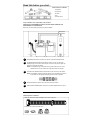
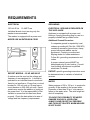
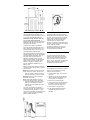
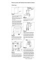
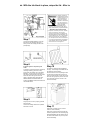
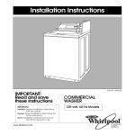
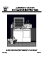
Read this before you start…
TOOLS needed for installation:
• Cutting knife
• Channel lock
• Nut driver
• Level
• Crescent wrench
Proper installation is the responsibility of the purchaser.
SERVICE CALLS PERFORMED AS A RESULT OF POOR INSTALLATION ARE THE
RESPONSIBILITY OF THE INSTALLER.
Make sure you have everything necessary for proper installation.
1
3
2
4
1
GROUNDED ELECTRICAL OUTLETS are required. See Electrical Requirements.
2
STANDPIPE DRAIN SYSTEM must be able to accept 1-1/2 inch O.D. drain hose.
Standpipe height of 36 inches is recommended. The drain must permit 23 gallon per
minute flow to evacuate the washer.
NOTE: If the standpipe height is less than 3 feet or greater than 5 feet, refer to the
“DRAIN FACILITY” section to determine if special provisions are needed.
3
HOT AND COLD WATER FAUCETS must be within 4 feet of the back of the washer.
NOTE: For installations requiring longer hose length, it is recommended to purchase a
double male 3/4” NH coupling and Maytag hose #33-7046 or equivalent.
4
WATER HEATER set to deliver 140°F (60°C) hot water to the washer.
5
PROTECTION FROM WEATHER: Do not store or operate washer below 60°F (15°C).
PARTS supplied for installation:
Cable tie to secure drain hose to standpipe, inlet hose or laundry tub
2 washers and 2 screens for water hoses
REQUIREMENTS
GROUNDING
ELECTRICAL
120 Volt 60 Hz
15 AMP Fuse
Individual branch circuit serving only the
washer is recommended.
The washer is equipped with a power cord.
NEVER USE AN EXTENSION CORD.
ELECTRICAL GROUND IS REQUIRED ON
THIS APPLIANCE.
Appliance is equipped with a power cord
having a 3-prong grounding plug for use in a
properly installed and grounded outlet.
Additional Ground Procedure:
If a separate ground is required by local
codes a grounding kit (Part No. 12001875)
containing accessory ground wire, clamp,
ground screw and washer can be
purchased. Contact your authorized
Maytag dealer for further assistance.
Follow ALL grounding requirements and
codes.
A proper external ground MUST be
determined prior to wire hookup. Consult
local building officials and a qualified
electrician if in doubt.
EXPORT MODELS – 50 HZ AND 60 HZ
A washer must be used on the voltage and
frequency it was designed for. It should be
operated on an individual branch circuit and
fused by no less than a 15 amp fuse or circuit
breaker for 120 volt units or 10 amp fuse or
circuit breaker on 220–240 volt units. Export
models may require the addition of a plug on
the power cord. It is the responsibility of the
installer to assure that this has been done
properly. Check the data plate to be sure of
voltage and line frequency requirements.
EXPORT–specific grounding instructions must
be determined due to variation of electrical
services.
WATER
Water pressure of 30 to 120 p.s.i. is required to
correctly fill the washer to the proper levels.
Pressures of less than 30 p.s.i. may cause a
failure to the water valve. The valve might not
shut off completely.
TO AVOID THE POSSIBILITY OF WATER
DAMAGE, SHOULD A HOSE LEAK,
ALWAYS HAVE FAUCETS ACCESSIBLE
AND TURN OFF FAUCETS WHEN WASHER
IS NOT IN USE.
CABINET DIMENSIONS
DRAIN FACILITY
FLOORING
Recommended height of standpipe is 36”.
The standpipe must be large enough to accept
a 1-1/2 inch outside diameter drain hose.
For best performance, the washer must be
installed on a solidly constructed floor. Wood
floors may need to be reinforced to minimize
vibration and/or unbalanced load situations.
Carpeting and soft tile surfaces are also
contributing factors in vibration and/or
tendency for a washer to move slightly during
spin cycle. Never install washer on a platform
or weak supported structure.
Without the 36” high elevation, water may
run out of the washer prematurely. A
possible sign that the drain hose has not been
elevated to proper height is if the washer fills
and drains at the same time.
The drain hose is attached at the factory.
A drain that will permit 23 gallons per minute
flow is required to evacuate the washer. The
standpipe should have a 1-1/2 inch minimum
internal diameter to prevent siphoning.
Tight connections between the drain hose and
the drain (standpipe, etc.) are not recommended
since they violate most plumbing codes. In
most cases where a tight connection is
demanded, an antisiphon valve should be
placed in the drain hose to prevent water from
siphoning from the washer or facility during
agitation. If required, an antisiphon valve
(Part No. 12001586) is available from your
dealer or store.
Refer to the drain height drawing to determine
if special provisions must be taken for the drain
hose and pump:
A Between the floor and 3 feet, the routing of
the drain hose is critical. Be sure that at
least some portion of the hose reaches a
height of 3 feet before running to the drain.
B Between 3 feet and 5 feet is the recommended drain height.
C For drain heights greater than 5 feet, a
high-volume pump (Part No. 12001587)
may improve draining performance, especially if the unit provides a customized
cycle with a slow spin speed (refer to the
User’s Guide).
If the drain hose needs to be extended to
reach the drain facility, an accessory kit must
be obtained (Part No. 12001585). If a highvolume pump is purchased, the extension kit is
included. Contact your authorized Maytag
dealer for further assistance.
If installing on carpeting, be sure there is
adequate clearance between carpet and
moving parts beneath the washer.
LOCATION CONSIDERATIONS
It is recommended the washer never be
installed in areas where water may freeze,
since the washer will always maintain some
water in the water valve, pump and hose
areas. This can cause damage to belts, pump,
hoses and other components. Operating
temperature should be above 60°F.
COLD WEATHER STORAGE
The following precautions should be taken if a
washer is to be stored where it would be
subject to freezing conditions.
1. Turn off the water supply, and remove the
inlet hoses.
2. Select a fill cycle and energize the water
valve by selecting a warm water setting.
A few seconds of fill is sufficient.
3. Disconnect from electrical supply.
4. Lower the drain hose to floor level and tip
the washer on its back to allow water to
drain from the pump and drain hose.
5. Return washer to upright position.
6. 30 day detergent dispenser should be
completely emptied (on models so
equipped).
Remove parts and literature from inside of washer
Start here…
Step 1
• Remove the carton by cutting only marked
areas of the carton. CAUTION: Hoses are
connected to the washer.
NOTE: If the washer is moved without the
carton in place, be sure to keep sharp edges
from damaging the washer cabinet or
attached hoses.
• Lift the carton up and clear of the washer.
Carefully remove any packaging materials
from the outside of the washer. NOTE:
Retain the corner posts for later use.
Step 4
Run water through faucets to remove particles
that might clog the water hoses. Determine
which of the faucets is hot and place an
identifying mark on it.
• Untape and raise the washer lid. Remove the
styrofoam tub block, remove the items shipped
in the spin basket, then replace the tub block.
Save the literature for future reference. Close
and tape lid.
Step 5
Step 2
With the tub block in place and the lid taped
shut, lay corner posts on the floor, as shown.
Use one corner post to support the top, and
three posts for the bottom. Gently tip the
washer on its back, laying it across the corner
posts.
Water hoses are attached to the washer and
labeled as “Hot” and “Cold.” Push the screens
and washers (located in the parts package)
into the remaining ends of the hoses. Attach
the “Hot” and “Cold” hoses to the corresponding faucets. Tighten by hand until snug and
then an additional 2/3 turn with pliers. Turn on
faucets to check for leaks at the faucet and
machine. Tighten if necessary. Fill hoses
should have slack in them when attached to
faucets.
Front Feet
Backguard
Step 6
Pop plastic
away from or
remove hex
head screw
Shipping
Base
Carton corner
posts (stacked
on each other)
Corner
Post
Step 3
Pop the plastic shipping base away from the
metal baseframe, or remove the hex head
screw at the rear. Pull plastic base away from
rear feet, and pull downward to disengage
from front feet. Recycle or discard the plastic
base. Return washer to upright position.
Unhook the hose retainer and drain hose from
the back of the cabinet and place the drain
hose in the drain facility (standpipe, laundry
tub, etc). A small amount of water may still be
in the drain hose from factory testing. The
height of the drain facility is important. Refer
to the “DRAIN FACILITY” section to determine
if special provisions are needed. NOTE: Do
not remove the hose retainer from the drain
hose. If the hose is twisted after it has been
placed in the drain, adjust the end of the hose
to remove the twist. To remove the twist, turn
the short end of the hose while holding the
base of the hose stationary.
NOTE: If you must make an airtight seal, an
antisiphon kit must be used.
tub. With the tub block in place, retape the lid. After ins
●
Improper connection of
the equipment-grounding
conductor can result in a
risk of electrical shock.
Check with a qualified
electrician or serviceman
if you are in doubt as to
whether the appliance is
properly grounded.
● Do not modify the plug provided with the
appliance – if it will not fit the outlet, have a
proper outlet installed by a qualified electrician.
●
Step 7
To prevent accidental dislodging, secure the
drain hose to the standpipe, inlet hose, or
laundry tub with the tie strap provided in the
parts package.
IMPORTANT SAFETY PRECAUTIONS
To prevent unnecessary risk of fire, electrical
shock or personal injur y, all wiring and
grounding must be done in accordance with
the National Electrical Code ANSI/NFPA, No.
70-Latest Revision (for U.S.) or the Canadian
Electrical code CSA C22.1-Latest Revision
(for Canada) and local codes and ordinances.
It is the personal responsibility and obligation
of the appliance owner to provide adequate
electrical services for this appliance.
Step 8
If separate ground is required by local
codes:
An accessory grounding kit (Part No. 12001875)
containing accessory ground wire, clamp,
ground screw and washer can be purchased
separately, Connect ground wire to back of
unit with the cabinet ground screw and washer.
Secure the other end of ground wire with
clamp to grounded COLD metal water pipe.
NEVER CONNECT GROUND WIRE TO
PLASTIC PLUMBING LINES, GAS LINES, OR
HOT WATER PIPES.
Step 10
The washer is equipped with self-stabilizing
rear legs. The front legs are threaded and can
be adjusted to level the washer.
Place the washer in its final operating location.
Tilt the machine forward until the rear of the
machine is approximately 4 inches off the floor.
Allow the unit to gently drop onto the rear feet.
This causes the rear feet to conform to the
floor and seat solidly.
Step 9
Plug the power cord into a properly grounded
electrical outlet.
Consult local building officials and a qualified
electrician if in doubt.
Step 11
With hands on opposite corners, rock the
washer to check for stability.
With a level, check the washer and make the
necessary adjustments to the front leveling legs.
NOTE:Self-stabilizing rear legs level the rear of
the machine side-to-side. They do not provide
front-to-back leveling.
tallation is completed, be sure to remove tub block.
Step 12
Once the machine is level, tighten both front
leveling leg locking nuts with a wrench. Once
again, reset the rear stabilizer as described in
Step 10. On models equipped with a felt
sound deflector under the front of the machine,
the felt should be tucked under the machine.
Step 14
Check the operation by using the check list
provided.
Step 13
Remove tape from the lid. Open the lid to
remove the styrofoam tub block. Remove any
remaining shipping materials.
Remove the protective film from the fascia.
CHECK LIST
■ Tub block, parts package and instructions have been removed from the tub.
■ Washer has been properly grounded and plugged into a polarized electrical outlet.
■ Water has been turned on. Check for leaks at faucets and water valve connections.
■ Drain hose is properly located into drain facility and is not twisted or kinked.
■ Washer has been leveled with legs firmly on the floor. The front leveling legs’ locking nuts
have been tightened.
■ Fill washer, checking for the correct water temperature.
■ After the washer has filled, let the washer agitate.
■ Spin the water out.
■ Demonstrate washer usage to consumer. Be sure to leave these instructions and the
User’s Guide with the owner.