1
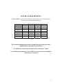
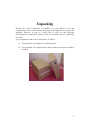
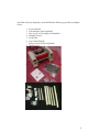
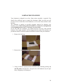
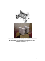
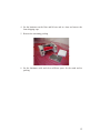
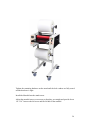
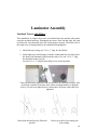
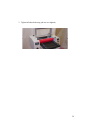
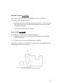
Professional Laminating Systems
SERIES II LAMINATOR
INSTALLERS
GUIDE
3
WARNINGS & SAFETY _______________________________ 5
ELECRICAL REQUIREMENTS __________________________6
Specifications ______________________________________________ 7
Unpacking _____________________________________________8
LAMINATOR UNPACKING ____________________________10
STAND ASSEMBLY____________________________________13
Assembled Stand _______________________________________15
Stand Assembly ________________________________________17
MOUNTING THE LAMINATOR _____________________________ 24
Laminator Assembly ____________________________________28
Standard Towers with Slitters _______________________ 28
Standard Towers w/o Slitters________________________ 30
Lower towers w/o Stand ___________________________ 30
Gapping Handle __________________________________ 31
Feed Table Installation_____________________________ 34
Feed Table Installation_____________________________ 34
Slitters _________________________________________ 35
4
WARNINGS & SAFETY
DO NOT OPERATE THIS LAMINATOR WITHOUT FIRST REVIEWING THE OPERATORS MANUAL IN
ITS ENTIRETY.
NEVER OPERATE THIS MACHINE WITH REMOVED, DAMAGED OR
MISSING PARTS - SHUTDOWN AND DISCONNECT FROM THE ELECTRICAL SUPPLY.
IF THERE WERE TO EVER BE A MECHANICAL OR ELECTRICAL MALFUNCTION IMMEDIATELY UNPLUG
THE MACHINE
NEVER SERVICE THIS MACHINE WITHOUT FIRST DISCONNECTING THE MACHINE FROM THE
ELECTRICAL SOURCE.
DO NOT TOUCH THE HEATED ROLLERS AS THEIR TEMPERATURE MAY EXCEED 350 DEGREES
FAHRENHEIT.
NEVER ALLOW SHARP OBJECTS SUCH AS KNIVES OR SCISSORS TO CONTACT THE ROLLER SURFACE AS
A POTENTIAL SHOCK HAZARD EXISTS AS WELL AS THE POTENTIAL TO INFLICT SERIOUS AND
IRREPARABLE DAMAGE TO THE SILICONE ROLL COVERING OR THE OPERATOR.
CAUTION MUST BE EXERCISED TO KEEP HANDS FROM THE NIP POINT OF THE LAMINATING AND PULL
ROLLERS TO AVOID INJURY DUE TO HIGH PRESSURE AND HEAT AT THESE POINTS.
FAMILIARIZE YOURSELF WITH THE REVERSE FEATURE, DO NOT WEAR LOOSE-FITTING CLOTHING
AND JEWELRY AND HAIR MUST BE PUT UP AND KEPT AWAY FROM THE NIP POINT THESE ITEMS
COULD BE PULLED INTO THE LAMINATOR SINCE THE ROLLERS ARE ROTATING.
USE MULTIPLE PEOPLE TO UNPACK AND MOVE THE LAMINATOR AS IT WEIGHS IN EXCESS OF 75
POUNDS. LEAVE REPAIRS AND MAINTENANCE TO A QUALIFIED PERSONNEL.
NEVER LEAVE THE MACHINE UNATTENDED WHILE IN USE.
SHUT THE MACHINE DOWN AND ALWAYS KEEP ROLLERS GAPPED WHILE THE MACHINE IS NOT BEING
ATTENDED. THIS GREATLY EXTENDS THE LIFE OF THE ROLLERS AS WELL AS SAVING $ IN LOST
ENERGY. REMEMBER YOUR NEW LAMINATOR TAKES AS FEW AS 4 TO 5 MINUTES TO WARM UP
RATHER THAN 20 OR 30
DO NOT ALLOW THE ROLLERS TO EXCEED 300 DEGREES DOING THIS WILL GREATLY INCREASE THE
LIFE OF THE LAMINATING ROLLERS – THOUGH YOUR MACHINE IS PERFECTLY CAPABLE OF RUNNING
FILM RATED AT 300 DEGREES PRO-LAM RECOMMENDS USING A FILM THAT IS RATED AT A LOWER
TEMPERATURE - THIS WILL INCREASE YOUR ROLLER LIFE
DO NOT ADVANCE THE FILM THROUGH THE LAMINATOR WHILE THE ROLLERS ARE COLD THIS MAY
RESULT IN THE SURFACE BEING TORN FROM THE ROLLERS BY THE AGGRESSIVE LAMINATING FILM
ADHESIVE.
DO NOT PLACE THE LAMINATOR NEAR MOVING AIR AS THIS MAY UNPREDICTABLY COOL THE
ROLLERS.
5
ELECRICAL REQUIREMENTS
A GROUNDED RECEPTICAL MUST BE USED, MAKE SURE THAT THE RECEPTICAL
MATCHES THE MACHINE REQUIREMENTS
MODEL
PL1200XS
PL1200HP
PL227
PL227HP
PL238
PL238wf
PL244wf
VOLTS
120
120
120
240
120
240
240
AMPS
10
20
20
20
20
20
30
PLUG
*
*
*
L6-20
*
L6-20
L6-30
*Conventional plug however the outlet must be dedicated (no other devices on the same
circuit).
The electrical installation must meet local and federal electrical codes and a
qualified person must make the installation.
If a laminator is hard wired you must install a “disconnect” switch
!!! These Requirements must be strictly adhered to, as an incorrect installation
will void your warranty!!!
6
Specifications
Hard specs
Model
Dry/Ship
weight
40# / 60#
Height
Width
Depth
PL 1200
21”
24”
21”
w/o stand
PL 1200
60# / 80#
51”
24”
21”
w- stand
PL 227w/o 70# / 100# 21”
39”
21”
stand
PL 227w
90# /120# 51”
39”
21”
stand
PL 238wf
140# / 170# 50”
50”
21”
PL 244wf
170# / 200# 50”
56”
21”
Models shown in their standard configuration
Film specs:
Model
Max
upper roll
11”
Max
lower roll
6”
Max
thickness
10 mil+
Max motor
Speed
18fpm
PL 1200
w/o stand
PL 1200
11”
12”
10 mil+
18fpm
w- stand
PL 227
11”
6”
10 mil
16fpm
w/o stand
PL 227
11”
12”
10 mil
16fpm
w stand
PL 238wf 10”
12’
5-10 mil
7fpm
PL 244wf 10”
12”
5-10 mil
7fpm
Standard models in their standard configuration
7
Unpacking
Because the series II laminator is available in several different sizes and
configurations, some of the following steps may not be applicable to your specific
shipment. However, it may be a good idea to read over the following
documentation to familiarize yourself with your machine and the technology
involved
Typical shipment of the series II laminator is as follows.
A. Your laminator was shipped as a tabletop model.
B. Your laminator was shipped with a stand and the stand requires minimal
assembly
8
Included with your shipment you should find the following, possibly in multiple
boxes.
1.
2.
3.
4.
5.
6.
7.
8.
Your laminator
The laminator stand (optional)
One set (2) of film supply roll mandrels
Mandrel Towers
Feed Table
Gap Control Handle
Release Liner Winder (Optional)
Hardware kit
9
LAMINATOR UNPACKING
Your laminator is shipped in one box. Some minor assembly is required. You
should clear sufficient space to unpack the laminator. Make sure this area will
provide access to both sides of the laminator as well as the front and back of the
machine.
The laminator is packed in specially designed material for shipping your
laminator safely The Packing material should be retained for transportation
or for shipping in the event of a warranty or service issue.
In the box with the laminator you should find the feed tray and enclosed
hardware. The supply mandrels will be shipped with the stand if the machine was
purchased without a stand the mandrels should be included with your laminator.
1. Remove the feed tray
2. Remove the center piece of foam
3. Using at least two people pull the laminator and remaining packing, by
the lift points, from the box. Use great care, the laminator may be quite
heavy, dropping it will damage it.
10
! ! ! DO NOT LIFT THE LAMINATOR BY ANY OF THE COMPONENTS
BETWEEN THE FRONT ROLLERS AND THE REAR ROLLERS.
DAMAGE MAY OCCUR ! ! !
11
4. Set the laminator on the floor and lift one end at a time and remove the
foam shipping caps
5. Remove the remaining packing
6. Set the laminator aside and clear sufficient space for the stand and its
packing
12
STAND ASSEMBLY
The stand is an optional item on certain models and may or may not have
been included with the purchase of your laminator.
Your laminator stand will require simple assembly. You should clear out
sufficient space to unpack the stand. Make sure this area will provide access to
both sides as well as the front and back of the stand.
Hardware Identified as:
5/16-18 Button head
Socket Cap Screw
8 pieces
5/16 Flat Washer
5/16 Split Washer
8 pieces
8 pieces
5/16-18 x ¾” Button Head
Socket Cap Screw
8 pieces
Mandrel Tower
2 pieces, 1 right one left
¼-20 x 3/4” hex head
Flange screw
13
Stand parts:
Stand Frame Riser
2 pieces
Stand Frame Base
2 pieces
Spreaders
1 piece typical
Top Support
14
Assembled Stand
Use the diagrams and instruction on the following pages as a guide to assemble
the stand
When finished your stand should resemble this example from our PL 227hp
without attached towers.
Unpack all of the parts and lay them out for accessibility
15
Install the Casters onto the base.
Make sure the caster is screwed all the way down such as in the left example.
16
Stand Assembly
Lay the base on its side and install the riser.
At this point there is not specific alignment to pay attention to, simply attach the
riser as shown.
17
Take note of this illustration that shows the proper bolt placement.
When first tightening the stand, only tighten it enough to start to seat the lock
washers.
18
Tighten the screw until the head of the screw just starts to compress the lock
washer but no tighter.
Position the now assembled sides so that the tower screws holes are located to the
front. The spreader will be placed in between, you are now looking at the front of
the stand.
Place the spreader in between the two stand sides, take note of the mandrel tower
holes
19
Tighten the screws down until the screw head just starts to compress the lock
washer.
20
Install the machine base to the top of the riser as shown. The only orientation that
matters is that the angle is mounted to the outside of the stand.
Install the other side and tighten the screws until they are snug but not tight
21
Install the towers next. There is a right hand and a left hand tower
Pay careful attention to the following picture and the orientation of the mandrel
tower.
22
Test fit the mandrel, make sure that it fits between the mandrel brackets
without the left mandrel bracket putting pressure on the mandrel, you should
have a small space between the mandrel bracket and the mandrel as shown. If
not, your mandrel brackets will have to be adjusted later.
23
MOUNTING THE LAMINATOR
Set the stand in position on a flat level surface.
Using 2-3 people carefully the laminator on top of the stand, align the inside of
the stand with the inside of the panel that sits on it, align the front of the stand
with the front of the panel. Install the ¼-20 hex head screws with their respective
washers through the holes in the top rail. DO NOT tighten these screws.
The screw bosses on the bottom of the machine should drop into the pockets on
the top stand rail and there should be no space left between the top rail on the
stand and the bottom of the machine. Since the components of the stand have not
been tightened, it may be necessary to forcefully align each screw pocket with
each screw boss.
24
Incorrect
Correct
If necessary, install and tighten each screw as you get each screw boss aligned
with each pocket. Tighten the ¼ ” bolts from the bottom side of the stand rail. DO
NOT over-tighten the screws they simply need to be snug.
25
Tighten the remaining hardware on the stand until the lock washers are fully seated
and the hardware is tight.
Install the Mandrel into the stand towers
Adjust the mandrel towers as necessary so that they are straight and provide about
1/8 -3/16” between the left tower and the left hub of the mandrel.
26
To adjust the mandrel towers, slightly loosen the 5/16” screws that hold the towers
to the stand then tighten the small allen screws to tilt the tower in the desired
direction, when adjusting the tower to the left, one should always adjust the screws
equally top and bottom. This will alleviate mandrel misalignment issues later on.
27
Laminator Assembly
Standard Towers with Slitters
This installation is simple; the towers are installed onto the machine side panels
using the included hardware. Distinguish the towers from left and right, the right
tower has the extra threaded hole with a ball plunger inserted. The inside face of
this right tower is distinguished by the chamfered mounting hole.
1. Install left tower using two 5/16 x ½” long, hex head bolts.
2. Install right tower (ball plunger) with the countersunk hole located toward
the front of the laminator and toward the center. Use one 5/16 x ½” long,
hex head bolt in the rear hole
Use one 5/16 x ½” long flat head Allen screw in the front hole
Take note that on the right tower the rear bolt must be oriented so that the side
of the bolt is parallel to the side of the slitter-actuating handle (see diagram
below.). Do not over tighten bolt it is better that it be looser rather than over
tightened
Correct
Notice both bolt and arm lay flush and
parallel
Incorrect,
Notice tip on bolt is preventing arm
from seating
28
3. Tighten all other bolts snug (do not over tighten).
29
Standard Towers w/o Slitters
These towers will be included with the hardware pack they do not have a
particular orientation (unidirectional)
4. Install towers on the left and right side using two 5/16 x ½” long, hex head
bolts each. These towers are ambidextrous and bidirectional, they cannot
be installed backward.
5. Tighten bolts snug (do not over tighten).
Lower towers w/o Stand
Your machine is available in two different configurations.
A. Without a stand, your towers will have to be installed on the laminator
below the feed tray.
B. With a stand, your towers should already be installed
Lower tower installation on the machine is similar to the tower installation for the
standard upper towers (without slitters).
Lower machine tower, viewed from left side.
30
Gapping Handle
The gapping handle is included in the hardware pack that came with your
laminator
This handle is for raising and lowering the rollers. The rollers should remain in
the gapped or raised position unless the machine is in operation.
To install,
Thread onto the end of the camshaft located on the right side of the machine.
31
(machine shown with optional tower, disregard differences)
To operate,
Simply turn clockwise, the rollers will raise and lower with every revolution of
the handle.
When adjusting the roller pressures make sure that the handle is in the un-gapped
position, after making adjustments gap and ungap the rollers to make sure that
you did not put too much pressure on the rollers for the cam (gapping handle) to
operate.
32
Gapped Rollers
Ungapped Rollers
33
Feed Table Installation
Feed Table Installation
1. When installing the feed table it should be held level and square in relation with
the laminating roller and with the front of the feed tray tilted as shown. 2. Slide
the table forward until the pin boss is against the pin and 3. Drop the front down
so that the second pin locks the table in place.
When placing the feed table onto the laminator, always be sure that the
laminator is turned off and the rollers are stationary.
Machine with installed table
34
Slitters
Cut the rubber bands that hold the slitter components from loosening during
shipment. Cut the rubber band that holds the slitter handle to the upper idler bar.
Separate the slitters by loosening the top from their positions juxtaposed from
each other
35
Included in the white box with your laminator are the slitter blades, do not install
them unless you are using them, always remove them after use, they are a
component as shown below and should be stored in a separate container (white
shipping box) with a lid.
They are extremely sharp and pose a cut hazard. Always be careful while
handling the sharp blades. Keep out of reach of children. Never use the slitters in
the presence of children or other incompetent (unqualified) people.
36
Startup:
After any service is performed on the machine or on the initial setup after
shipping.
Reveiw the following, BEFORE YOU FIRST PLUG IN THE MACHINE!
You MUST follow this procedure in this order. Use caution, you can burn
yourself easily on the laminating rollers it is advisable to use leather gloves for a
preliminary heat check of the rollers.
1.
Turn all switches to off.
2.
Plug the laminator in. Do not leave the laminator plugged in for more
than 3 minutes. DO NOT Leave the machine unattended during this
startup procedure without unplugging it!!!
3.
Feel the rollers – top and bottom for a minute or so to see if they are
warming up, if they do, immediately unplug the machine and contact
tech support. (406-363-6145). Do not plug the machine back in, lock it
out if necessary. If they do not heat, continue to 4.
4.
Turn the temperature
counterclockwise)
5.
Turn on the heat / power switch
6.
Watch the temperature display and make sure that it does not gain
temperature. Also feel both bottom and top rollers making sure that they
are not heating (if the room is rather cold the laminator may heat but
certainly not over 80 degrees). If the laminator heats beyond this point or
room temperature, immediately unplug the machine and contact tech
support. (406-363-6145). Do not plug the machine back in, lock it out if
necessary.- your temperature control may need to be replaced. if your
machine does not heat, continue to 7.
7.
If only one roller heats, immediately unplug the machine and contact
tech support. (406-363-6145). Do not plug the machine back in, lock it
out if necessary. If neither roller heats, continue to 8.
8.
Turn the temperature control to your normal operating temperature or
250 degrees and feel the rollers to make sure they are warming equally
(don’t burn yourself yet). If they are warming watch the machine until it
is heated to its operating temperature make sure that it stops heating at
the correct setting.
9.
If you have reached this step without any errors, you are now ready to
laminate, your laminator can regulate its own temperature.
37
control
to
its
minimum
setting
(full
***If at any time the laminator does anything unusual or continues to heat when it
should not immediately unplug the machine and contact tech support***
PLEASE PROCEED TO THE OPERATORS MANUAL
Keep this manual for future reference
38
39
40