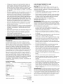
1
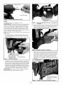
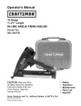
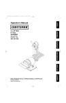
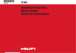
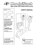
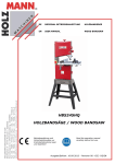
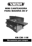
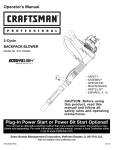
Operator's
Manual
®
11/4-
21/2"
Length
COIL UTILITY NAILER
Model No.
351.182140
CAUTION:
•
•
•
•
•
Read and follow
all Safety Rules and Operating
Instructions before First Use
of this Product. Keep this
manual with tool.
Sears, Roebuck and Co., Hoffman
www.sears.com/craftsman
21662.00 Draft (01/12/04)
Estates, IL 60179 U.S.A.
Safety
Operation
Maintenance
Parts List
Espa5ol
Warranty .........................................
2
Safety Rules ......................................
2
Operation ......................................
Maintenance .....................................
3-6
6
Troubleshooting ...................................
Parts Illustration and List ..........................
7
8-9
EspaSol ......................................
FULL
*
The tool must have a male, free-flow hose coupling so that
all air pressure is removed from the tool when the coupling
joint is disconnected. Failure to use proper coupling could
cause accidental discharge, possibly causing injury.
*
Only use air hose that is rated for a maximum working
pressure of 150 psi or 150% of the maximum system pressure, whichever is greater.
Do not use a hose swivel connector with this tool.
*
*
Do not pull trigger or depress contact trip while connecting
to the air supply, as the tool may cycle, possibly causing
injury.
*
When loading tool: Do not pull trigger or depress contact
trip; Do not point the tool at yourself or others; Do not
place hand or any part of body in the fastener discharge
area of the tool as accidental actuation may occur and
cause injury.
*
Disconnect tool from air supply before loading or unloading, performing tool maintenance, clearing a jammed fastener, leaving work area, moving tool to another location or
handing the tool to another person.
*
Use Sears recommended
*
Do not load the tool until you are ready to use it.
*
Always assume that the tool contains fasteners. Keep the
tool pointed away from yourself and others at all times.
Never engage in horseplay. Never pull the trigger unless
the contact trip is in contact with the workpiece. Keep others at a safe distance from the tool while the tool is in
operation.
*
Always remove finger from trigger when not driving fasteners. Never carry the tool with finger on or under the trigger
as accidental actuation may occur and cause injury.
*
Always keep hands and body away from the fastener discharge area when air supply is connected to the tool. Grip
tool firmly to maintain control while allowing tool to recoil
away from work surface as fastener is driven. If contact trip
is allowed to recontact work surface before trigger is
released, an unwanted fastener may be driven.
*
Check operation of the contact trip frequently. Never use
the tool if the contact trip, trigger or springs have become
inoperable, missing or damaged. Do not alter or remove
contact trip, trigger or springs. Never use a tool that is leaking air, has missing or damaged parts, or requires repair.
*
Do not drive fasteners on top of other fasteners or with the
tool at too steep an angle. The fasteners can ricochet and
cause injury. Do not drive fasteners close to the edge of
the workpiece. The workpiece is likely to split, allowing the
fastener to fly free and cause injury. Do not attempt to
drive fasteners into hard or brittle materials such as concrete, steel or tile.
*
Do not overreach. Always place yourself in a firmly balanced position when using or handling the tool. Do not
attach the hose or tool to your body.
*
Do not operate tool without fasteners or damage to tool
may result.
Do not use tool without safety warning label. If label is
missing, damaged or unreadable, contact SEARS to
obtain a new label.
10-15
ONE YEAR WARRANTY
If this product fails due to a defect in material or workmanship
within one year from the date of purchase, Sears will at its
option repair or replace it free of charge. Contact your nearest
Sears Service Center (1-800-4-MY-HOME) to arrange for
product repair, or return this product to place of purchase for
replacement.
If this product is used for commercial or rental purposes, this
warranty will apply for 90 days from the date of purchase.
This warranty applies only while this product is used in the
United States.
This warranty gives you specific legal rights, and you may also
have other rights which vary from state to state.
Sears, Roebuck and Co., Dept. 817WA, Hoffman Estates,
IL 60179
*
Read and follow all safety rules and operating instructions
in this manual and on warning label of tool before using
this tool. Keep this manual with the tool.
*
Keep work area clean and properly lighted.
*
Keep children, bystanders and visitors at a safe distance
from work area while operating this tool.
*
Air tool operators and all others in work area should
always wear safety goggles complying with United States
ANSI Z87.1 to prevent eye injury from fasteners and flying
debris when loading, operating and unloading this tool.
Everyday eyeglasses have only impact resistant lenses.
These are NOT safety glasses. ANSI Z87.1 safety glasses
have permanently attached rigid, hard plastic side shields
and will have "Z87.1" printed or stamped on them.
*
*
Always wear ear protection. The work area may include
exposure to excessive noise levels which will require necessary ear protection. Some environments will require
head protection; use head protection conforming to ANSI
Z89.1.
Do not alter or modify this tool in any way. Do not use this
tool for any application other than for which it was
designed.
fasteners only.
*
Do not use oxygen, carbon dioxide, high-pressure compressed gas or bottled gases as the power source for this
tool. The tool will explode and serious personal injury
could result.
*
*
Only qualified repair personnel must perform tool service.
*
Never connect the tool to air pressure which could potentially exceed 200 psi. Use only clean, dry, regulated air
within rated range as marked on tool.
*
*
When servicing a tool, use only identical repair parts.
Store tool out of reach of children and other untrained
© Sears, Roebuck and Co.
persons.
2
°
DESCRIPTION
The Craftsman Coil Utility Nailer drives full head nails from
1_/4"to 2W' long. Magazine will hold a coil of 400 wire
collated nails. Safety feature disables tool unless contact trip
is pressed against workpiece. Sequential trigger switch allows
selection of rapid-fire or single-fire mode. Contact trip can be
adjusted for setting nail depth. Plastic protector on the end of
contact trip prevents marring of workpiece. Air deflector can
be adjusted to any direction. Die cast aluminum body with
textured rubber grip minimizes operator fatigue and makes
nailer lightweight and durable. The coil utility nailer is excellent
for siding, sheathing, exterior trim, subflooring, decking and
fencing.
SPECIFICATIONS
Capacity .....................
Nail size .......................
400 wire collated coil nails
0.082 to .110" diameter
Nail lengths ...............................
Operating pressure ........................
Air inlet ...................................
1_ to 2_/2''
65-110 PSI
W' N.P.T.
Length .......................................
103/4
''
Height .......................................
Width ..........................................
11%"
5"
Weight .....................................
All hoses and pipes in the air supply system must be clean
and free of moisture and foreign particles. Hoses must be
rated for a maximum working pressure of 150 PSI or 150%
of maximum system pressure, whichever is greater.
° Do not mount swivel connector in air supply line.
° The air pressure should be properly regulated.
° Different workpiece materials and different fastener lengths
will require different operating pressure.
° Be sure all connections in air supply system are sealed to
prevent air loss.
° Never connect a female quick-disconnect coupling to the
tool side of air line connection. A male, free-flow coupling
should be connected to the tool side of air line connection
(see Figure 1).
WARNING:
The female coupling provides a seal preventing
loss of compressed air from compressor tank when disconnected from male coupling. If connected to tool side of air
supply, the female coupling could seal a compressed air
charge in the tool which could discharge if the tool trigger is
actuated.
I
Male Connector
4.2 Ibs.
NAILS
18081 (Box of 8000) ...........
18082 (Box of 6000) ............
AIR SUPPLY
Galvanized nails, 13/4
'' long
Galvanized nails, 2" long
Female Connector
LINE
Refer to Figure 1.
DANGER: De not use oxygen, carbon dioxide, high-pressure
compressed gas or bottled gases as the power source for this
tool. The tool will explode and serious personal injury could
result.
•
The air tool operates on compressed
65 to 110 PSI.
air at pressures from
•
Never connect the tool to air pressure which could potentially exceed 200 PSI. Use only clean, dry, regulated air
within rated range as marked on tool.
Air Delivery Required: 1.87 SCFM @ 90 PSI
(30 shots per minute).
WARNING:
Keep hands and body away from discharge area
of tool when connecting air supply. Always disconnect tool
from air supply when servicing or adjusting tool and when tool
is not in use.
•
Air operated tools require clean, dry, lubricated compressed air to ensure top performance, low maintenance
and long life.
•
Dirt and abrasive materials present in all air lines will damage tool O-rings, valves and cylinders.
Moisture will reduce tool performance and life if not
removed from compressed air.
A filter-regulator-lubricator system is required and should be
located as close to tool as possible. A distance of less than
15 feet is recommended.
•
•
•
•
Keep air filter clean. A dirty filter will reduce the air pressure
to the tool causing a reduction in power and efficiency.
The air supply system must be able to provide air pressure
of 65 to 110 pounds per square inch at tool.
Figure 1 - Air Supply Line
LOADING
Refer to Figures 2 through 6, (pages 3 and 4).
WARNING:
Disconnect tool from air supply. Do not load tool
until you are ready to use it. Do not pull trigger or depress
contact trip while loading tool. Always load with nose of tool
pointing away from you and others. Always wear safety goggles that comply with United States ANSI Z87.1.
NOTE: For best results, use Sears fasteners only.
•
Push the door latch down and swing the door open; then
swing the magazine cover open (see Figure 2).
Figure 2 - Opening
the magazine
°
The nail holder must be set to the length of the nails being
used. Twist the spindle of the nail holder and position nail
holder up or down so that the edge of the nail holder is
aligned with the correct size indicator on the inside of the
magazine. Twist spindle to lock nail holder in place (see
Figure 3).
Nail Heads Must be
Positioned in This Slot
CAUTION:
Failure to adjust nail holder height may result in
damage to advance mechanism.
....
,Second Nail Must Be
Positioned in Feed Jaw
Figure 5 - Load Nails into Feed Jaw
° Carefully close the magazine cover first. Then close the
door and secure in position with the latch. Make sure the
tab in the door holds the magazine cover in place
(see Figure 6).
\
Nail Holder
Figure 3 - Adjust Nail Holder for Length of Nail
°
Remove rubber band or tape holding nail coil. Place coil
over the spindle of nail holder in magazine (see Figure 4).
Figure 6 - Close the Magazine Cover and Door
NAILING
OPERATION
Refer to Figures 7 through 10 (page 5).
WARNING:
Read and follow all safety rules and operating
instructions in this manual and on warning label of tool before
using this tool. Keep this manual with the tool.
WARNING:
Do not use this tool without safety warning
label. If label is missing, damaged or unreadable, contact
Sears to obtain a new label.
Figure 4 - Load Coil into the Magazine
WARNING:
Never operate tool unless contact trip is in contact with workpiece. Do not operate tool without fasteners or
damage to tool may result. Never fire fasteners into the air
because fasteners may injure operator or others and damage
to tool may result.
Unwrap coil so that second nail can be placed between
sides of feed jaw. The ram (Fig. 11, No. 20) may need to be
pushed up to fit in the first nail. Make sure that the nail
heads are positioned in the slot at the top of the nail feed
rack (see Figure 5).
°
4
Perform "Safety Mechanism Check" as described in the
Maintenance section (see page 6) prior to first use of tool
and on a daily basis thereafter.
•
•
The tool is equipped with
to rapid-fire or single-fire
switch is set to single-fire
second fastener until the
pulled again.
CONTACT
a rotating switch that can be set
mode (see Figure 7). When the
mode, the tool will not drive a
trigger is fully released and
When the switch is rotated to rapid-fire
drive fasteners continuously. A fastener
time the contact trip is pressed against
long as the trigger is maintained in the
TRIP ADJUSTMENT
The contact trip may be adjusted up or down to vary the
driven depth of the fastener. To adjust, rotate depth control
knob (see Figure 8) to raise or lower contract trip to desired
setting.
mode, the tool can
will be fired each
the workpiece, as
pulled position.
Control
Knob
Figure 8 - Setting
CONTACT
•
OPERATION:
The air tool is equipped with a contact trip safety mechanism that disables tool unless contact trip is pushed
against work. To drive a fastener hold body firmly and
press contact trip on workpiece where fastener is to be
applied. Pull trigger to drive fastener into workpiece. To fire
a second fastener lift the tool from the workpiece, release
the trigger and then repeat the above sequence.
RAPID-FIRE
•
PAD STORAGE
Pad can be removed and stored on the storage sleeve located on the magazine (see Figure 9).
Figure 7 - Push and Rotate Switch to Select
Operation Mode
SINGLE-FIRE
TRIP
Depth Control
OPERATION:
The tool can also be operated by holding trigger
depressed and pushing contact trip against workpiece. A
fastener will be driven each time the contact trip is pushed
against the workpiece. This operating procedure provides
rapid-fire fastener driving. Never operate tool unless contact trip is in contact with workpiece.
OPERATING
Figure 9 - Storing Contact Trip Pad
EXHAUST
°
PRESSURE
•
Use only enough air pressure to perform the operation. Air
pressure in excess of that which is required will make the
operation inefficient and may cause premature wear or
damage to the tool.
•
Determine minimum air pressure required by driving some
test fasteners into the workpiece. Set air pressure so that
test fasteners are driven down flush with the work surface.
Fasteners driven too deep may damage workpiece.
DEFLECTOR
Exhaust deflector can be positioned to point in any direction (full 360 ° movement). Reposition deflector by grasping
firmly and rotating to the desired position (see Figure 10).
Exhaust
Deflector.
WARNING:
All air power fastening tools recoil when operated. This recoil is caused by rapid driving of the fastener. Tool
may bounce from recoil causing a second unwanted fastener
to be driven. Reduce tool bounce by holding tool firmly in
hand and pressing tool gently against workpiece. Let the tool
do the work. This will allow recoil of tool to bounce tool away
from workpiece preventing the driving of second fastener.
Figure 10- Exhaust Deflector Adjustment
5
COLD WEATHER
OPERATION
CAUTION: Do not store in cold environment. Frost or ice
could form inside tool affecting operation and damaging tool.
Use a cold temperature lubricant, such as ethylene glycol,
when operating tool in freezing temperatures.
Refer to Figure 11.
LUBRICATION
Lubricate tool daily with quality air tool oil. If no air line lubricator is used, place five or six drops of oil into air inlet cap
(Figure 11, Key No. 27) of tool everyday.
MAGAZINE
•
AND PISTON-RAM
Keep magazine and nose of tool clean and free of any dirt,
lint or abrasive particles.
The tip of the ram (Figure 11, Key No. 20) can become
dented or rounded over time.
•
Square off the tip of the ram with a clean, fine hand file to
extend the life of the ram and tool. Fastener firing will be
more consistent if the ram tip is kept clean and square.
SAFETY
MECHANISM
CHECK
Inspect contact trip safety mechanism daily for proper operation. Do not operate tool if mechanism is not operating
properly.
With the red push-button switch in the rapid-fire mode, perform the following procedures to test safety mechanism:
•
Leave trigger untouched while pushing contact trip into
workpiece. Tool must not fire.
•
Pull trigger while contact trip is clear of work and pointed
away from operator and others. Tool must not fire.
•
Depress and hold trigger. Push contact trip against work
where fastener is needed. The tool should drive only one
fastener each time the contact trip is pushed against
workpiece.
If contact trip mechanism does not operate properly,
repair tool immediately through Sears Service Center.
Replace any damaged or missing parts. Use the parts list to
order parts.
REBUILD
KITS
Rebuild kits are available as spare parts, (see page 9). Tools
should be rebuilt if tool fails to operate properly after extended
use. See troubleshooting to determine required replacement
parts.
Disconnect tool from air supply
or adjustment.
before attempting
repair
NOTE: When replacing O-rings or cylinder, lubricate with
grease before assembly.
6
SYMPTOM
POSSIBLE
CAUSE(S)
CORRECTIVE
ACTION
Trigger cap leaks air
1. O-ring damaged
2. O-rings damaged
1. Check and replace damaged O-ring (Fig. 11, No. 30)
2. Check and replace damaged O-rings
(Fig. 11, Nos. 30, 32, 34, 37, 56 and 105)
Cap leaks air
1.
Cap bolts loose
2. Damaged cap gasket
1.
Tighten bolts (Fig. 11, No. 5)
2. Check and replace damaged gasket (Fig. 11, No. 9)
Nose leaks air
1. Damaged nose O-ring
2. Damaged bumper
3. Nose bolts loose
1. Check and replace damaged nose O-ring (Fig.11, No. 64)
2. Check and replace damaged bumper (Fig. 11, No. 24)
3. Tighten bolts (Fig. 11, No. 79)
Tool will net operate
1. Insufficient air supply
2. Damaged or worn head valve
O-rings or seal
3.
Damaged head valve spring
4. Head valve binding in cap
1. Check air supply
2. Replace damaged or worn seal or O-rings
(Fig. 11, Nes. 10, 12 and 15)
3.
Replace damaged spring (Fig. 11, No. 11)
4. Clean and lubricate cap and head valve
(Fig. 11, Nos. 4 and 14)
5.
Place five or six drops of air tool oil into air inlet cap
(Fig. 11, No. 27)
5. Insufficient lubrication
Tool operates slowly
or loses power
1. Damaged head valve spring
2. Damaged or worn O-rings
3. Damaged trigger assembly
4. Build-up on ram
5. Cylinder not sealed on bumper
properly
6. Insufficient air supply
7. Insufficient lubrication
8. Head valve poorly lubricated
Tool skips fasteners or
inconsistent operation
1. Feed piston not lubricated
2. Damaged feed piston O-rings
3. Jaws and/or pawls binding
4. Nail holder improperly adjusted
5. Defective coil nails, welded wires
on coil breaking
6.
Worn or damaged bumper
7. Build-up on ram or nose
8. Insufficient air supply
9. Damaged or worn piston O-ring
10. Insufficient lubrication
11. Fasteners too short
1. Check and replace damaged spring (Fig. 11, No. 11)
2. Replace damaged or worn O-rings
(Fig. 11, Nos. 12 and 15)
3. Check and replace trigger assembly
4. Clean and lubricate piston/ram assembly (Fig. 11, No. 20)
5. Disassemble cylinder and assemble properly
6. Check air supply
7. Place five or six drops of air tool oil into air inlet cap
(Fig. 11, No. 27)
8. Disassemble head valve (Fig. 11, No. 14), clean,
lubricate, and assemble properly
1. Lubricate feed piston (Fig. 11, No. 67) with air tool oil
2. Check and replace damaged O-rings
(Fig. 11, Nos. 12 and 32)
3. Check jaw and pawls (Fig. 11, Nos. 72, 81 and 83)
operation. Clean and lubricate jaw/pawls
Replace worn er damaged jaw/pawls
4. Adjust nail holder height properly
(refer to Figure 3, page 4)
5. Discard defective nails
6.
7.
8.
9.
10.
12. Damaged fasteners
11.
12.
13. Incorrect fastener size
14. Head valve O-rings leak
13.
14.
15. Damaged trigger valve O-rings
15.
16. Bent or damaged ram
16.
17. Dirty magazine
18. Damaged or worn magazine
17.
18.
Check and replace bumper (Fig. 11, No. 24)
Clean and lubricate piston/ram assembly (Fig. 10, No. 20)
Check air supply
Check and replace O-ring (Fig. 11, No. 19)
Place five or six drops of air tool oil into air inlet cap
(Fig. 11, No. 27)
Use Sears recommended fasteners only
Discard damaged fasteners and use
Sears recommended fasteners only
Use Sears recommended fasteners only
Check and replace damaged O-rings
(Fig. 11, Nos. 12 and 15)
Check and replace damaged O-rings
(Fig. 11, Nos. 30, 32, 34, 37, 56 and 105)
Check and replace damaged piston/ram assembly
(Fig. 11, No. 20)
Clean magazine and lubricate with air tool oil
Check and replace magazine
Model 351.182140
Figure 11 - Replacement
Parts Illustration
./"
//
For Coil Utility Nailer
18
0
_
19
27
23
26
\
25
_1Ol
44
4o!
45
99
"101
102
88
/
84
/
89
98
KEY
NO.
PART NO.
DESCRIPTION
1
2
3
4
5
6
7
8
9
10
11
12
13
14
15
16
17
18
19
20
21
22
23
24
25
26
27
28
29
30
31
32
33
34
35
36
37
38
39
40
41
42
43
44
45
46
47
48
49
50
51
52
53
54
STD870512
21587.00
21588.00
21589.00
STD870525
STD852005
21590.00
01210.00
21591.00
21592.00
21593.00
16249.00
21594.00
21595.00
21596.00
21597.00
07476.00
21598.00
04360.00
21599.00
08775.00
21600.00
21601.00
21602.00
N/A
07426.00
21044.00
21603.00
21604.00
16767.00
21605.00
06136.00
21606.00
04327.00
21607.00
21608.00
16331.00
21609.00
01873.00
17434.00
21610.00
21611.00
09622.00
06388.00
21612.00
21614.00
21613.00
21616.00
21617.00
21618.00
21619.00
21620.00
21621.00
21622.00
5-0.8 x 12mm Socket Head Bolt*
Retainer
Deflector
*
A
QTY.
Cap Cover
5-0.8 x 25mm Socket Head Bolt*
5mm Lock Washer*
Cap
5-0.8 x 5mm Set Screw
Gasket
Seal
Spring
20.8 x 2.4mm O-Ring
Spacer
Head Valve
44.7 x 3.5mm O-Ring
Collar
70.5 x 2.0mm O-Ring
Seal Ring
35.5 x 2.0mm O-Ring
Piston Ram Assembly
45.5 x 2.0mm O-Ring
Cylinder
45.7 x 3.5mm O-Ring
Bumper
Body
45.7 x 2.62mm O-Ring
Air Inlet Cap
17.12 x 2.62mm O-Ring
Trigger Head Valve
15.5 x 1.5mm O-Ring
O-Ring
8.8 x 1.9ram O-Ring
Valve Plunger
9.8 x 1.9mm O-Ring
Spring
Plunger
1.42 x 1.53mm O-Ring
Trigger Cap
3 x 22mm Spring Pin
3 x 30mm Spring Pin
Throttle
Spring
1/8" Steel Ball
3CMI-4 E-Ring
Spring
Contact Trip Guide
Spring
Spring Guide
Knob
2.0 x 14mm Spring Pin
Spring
Detent Ring
Set Ring
2.6 x 1.2mm O-Ring
1
1
1
1
4
4
1
1
1
1
1
2
1
1
1
1
1
1
1
1
1
1
1
1
1
1
1
1
1
1
2
2
1
1
1
1
1
1
1
3
1
1
1
1
1
1
1
1
1
1
1
1
1
1
Accessories
Qty./Box
NO.
Galvanized Nails, 13/4"long
8000
9-18081
A
Galvanized
6000
9-18082
DESCRIPTION
QTY.
21623.00
21624.00
21625.00
21626.00
06384.00
21627.00
21628.00
Depth Screw
9.0 x 2.0mm O-Ring
Contact Trip Cover
Contact Trip
3CMI-3 E-Ring
Trigger Assembly
Rubber Pad
1
1
1
1
1
1
1
62
63
64
65
66
67
21629.00
21630.00
06909.00
06064.00
21631.00
21632.00
Contact Trip Pad
Bushing
44.17 x 1.78ram O-Ring
3.8 x 1.9mm O-Ring
Nose
Feed Piston
1
1
1
1
1
1
68
69
70
21633.00
21634.00
21635.00
Spring
Feed Piston Bumper
Feed Piston Cover
1
1
1
71
72
73
06131.00
21636.00
15401.00
3BMI-28 Retaining Ring
Feed Jaw
4 x 22ram Dowel Pin
1
1
1
74
75
76
21637.00
21638.00
21639.00
Spring
Driver
Driver Pin
1
1
1
77
78
79
80
21640.00
STD852006
STD870620
21641.00
2.57 x 1.78mm O-Ring
6mm Lock Washer*
6-1.0 x 20ram Socket Head Bolt*
Door
1
4
4
1
81
82
83
84
85
86
21642.00
21643.00
21644.00
21645.00
21646.00
21647.00
Upper Retaining Pawl
Spring
Lower Retaining Pawl
Spring
Spring
Door Latch
1
1
1
1
1
1
87
88
89
90
21648.00
21649.00
STD870412
21650.00
2.84 x 2.62mm O-Ring
Door Cover
4-0.7 x 12ram Socket Head Bolt*
Door Pivot Pin
1
1
2
1
91
92
93
94
21651.00
21652.00
21653.00
21654.00
Magazine
Spring
Adjusting Post
Nail Holder
1
1
1
1
95
96
97
98
09033.00
21655.00
21656.00
21657.00
2.5 x 12ram Spring Pin
Clip
Cap
Pin
1
1
1
2
99
100
101
21658.00
STD870520
STD843508
2.8 x 1.9mm O-Ring
5-0.8 x 20ram Socket Head Bolt*
5mm Fiber Hex Nut*
3
2
2
102
103
104
21659.00
21660.00
21661.00
Magazine Cover
Magazine Spacer
Guard
1
1
1
105
A
A
A
21850.00
21710.00
21663.00
21662.00
3.5 x 1.5mm O-Ring
Warning Label
Storage Case
Operator's Manual
1
1
1
1
Kits
A
21704.00
A
21705.00
Trigger Rebuild Kit
Fig. 11, Nos. 30, 32, 34, 35, 36
37, 56 and 105
Head Valve Rebuild Kit
21706.00
Fig. 11, Nos. 9, 11, 12 and 15
Piston-Ram
Rebuild Kit
Model No.
A
Nails, 2" long
PART
55
56
57
58
59
60
61
Rebuild
Standard hardware item available locally
Not Shown
Recommended
KEY
NO.
A
1
1
1
Fig. 11, Nos. 9, 18, 19 and 20
A
A
21707.00
21708.00
Cylinder Rebuild Kit
Fig. 11, Nos. 9, 21,23
Feed Piston
Rebuild
1
and 24
Kit
Fig. 11, Nos. 12, 32, 67 and 69
1
lth - 272" de Iongitud
CLAVADORA DE CARRETE
DE USO PRACTICO
•
Modelo No.
351 •182140
•
permanentes
rigidas,
impreso o estampado
•
.............................................
y Lista de Partes ............................
Operaci6n
Mantenimiento
Identificaci6n
No utilice
de carbono,
COMPLETA
Si fallara este producto
14
15
•
DE UN ANO
por causa
de defectos
en el material
al establecimiento
donde
La herramienta
Qnicamente
se utiliza
Utilice Linicamente
presi6n de trabajo
•
Hoffman
vez. Mantenga
Mantenga
iluminada.
el Area de trabajo
en
•
•
Los operadores
de herramientas
neumaticas y todas las
demas personas presentes en el Area de trabajo deben usar
siempre gafas de seguridad que cumplan con los requisitos
producirse
la herramienta
una activaci6n
del abastecimiento
accidental
y
de aire antes
la herramienta a otra ubicaci6n
a otra persona.
Use Linicamente
los sujetadores
la herramienta
o entregarle
la
Sears recomendados.
No cargue
Asuma siempre que la herramienta
Mantenga la herramienta
apuntada
hasta que este listo para usarla.
contiene sujetadores.
en direcci6n contraria
a
usted y a otras personas en todo momento. Nunca juegue
con la herramienta.
Nunca oprima el gatillo a menos que el
disparo por contacto haya entrado en contacto con la pieza
de trabajo. Mantenga a toda persona a una distancia prudente
de la herramienta
mientras se encuentra en funcionamiento.
Aleje siempre los dedos del gatillo cuando no impulse sujetadores. Nunca transporte la herramienta con el dedo en el
gatillo o debajo de este ya que puede ocurrir
accidental y ocasionar lesiones.
•
Mantenga
siempre
las manos y el cuerpo
descarga de sujetadores
de aire a la herramienta.
una activaci6n
alejados del Area de
cuando se conecte un abastecimiento
Agarre la herramienta firmemente
para mantener el control a la vez que le permite rebotar lejos
de la superficie de trabajo cuando se impulsan los sujetadores.
Si se permite que el disparo por contacto vuelva a hacer con-
de la norma estadounidense
ANSI Z87.1, para evitar lesiones
oculares ocasionadas
por sujetadores y parficulas que salgan
disparadas al cargar, operar y descargar esta herramienta.
Los anteojos comunes tienen lentes que s61o son resistentes
al impacto. NO son anteojos de seguridad. Las gafas de
con protecciones
No oprima el gatillo ni presione
•
limpia y adecuadamente
cuentan
lesiones.
•
junto con la herramienta.
Mantenga a los niffos, a los visitantes y a toda otra persona a
una distancia prudente del Area de trabajo mientras hace funcionar esta herramienta.
Desconecte
jo, trasladar
herramienta
•
ANSI Z87.1
con esta herramienta.
de cargar o descargar, realizar el mantenimiento
de la herramienta, desatascar un sujetador, abandonar el Area de traba-
Estates,
•
seguridad
ocasionar
Cuando cargue la herramienta:
tadores ya que podrfa
ocasionar lesiones.
•
este manual
Io cual sea mayor.
el disparo por contacto; No apunte la herramienta
hacia usted
mismo o hacia otras personas; No coloque las manos ni
ninguna parte de su cuerpo en el Area de descarga de suje-
Lea y siga todas las reglas de seguridad e instrucciones
de
operaci6n incluidas en este manual yen la etiqueta de advertencia de la herramienta antes de utilizar este producto por
primera
•
and Co., Dept. 817WA,
una manguera de aire clasificada para una
maximo de 1034 kPa o 150% de la presi6n
del sistema,
cicla y podrfa
•
Esta garantfa le otorga derechos legales especfficos y tambien
puede usted tener otros derechos que varfen de estado a estado.
Sears, Roebuck
IL 60179
para
No oprima el gatillo ni presione el disparo por contacto mientras conecta el abastecimiento
de aire, ya que la herramienta
Io adquiri6.
si el producto
debe contar con un acoplamiento
No use un conector giratorio de manguera
Si este producto se usa para fines comerciales
o de alquiler, esta
garanfia es valida por 90 dias a partir de la fecha de compra.
Esta garantfa es aplicable
los Estados Unidos.
de
•
elecci6n, sin costo adicional. Solicite al Centro de Servicio
Sears (1-800-4-MY-HOME)
mas cercano la reparaci6n del
o devuelvalo
gas comprimido
•
o
en la mano de obra en un lapso de un afro a partir de la
fecha de compra, Sears Io reparara o reemplazar&
a su
producto
di6xido
a la
Nunca conecte la herramienta a una presi6n de aire que
pudiera exceder 1379 kPa. Utilice Linicamente aire regulado,
maxima
GARANTIA
oxfgeno,
manera.
diferente
conecte la junta del acoplamiento.
El uso de un acoplamiento
incorrecto podffa generar una descarga accidental y posiblemente ocasionar lesiones.
11-14
............................
de ninguna
para una aplicaci6n
manguera macho de fiujo libre de manera que la presi6n
del aire pueda removerse de la herramienta
cuando se des-
10-11
.......................................
de Problemas
•
10
...............................
esta herramienta
No utilice esta herramienta
que fue diseffada.
limpio y seco que se encuentre dentro de la gama de capacidad nominal indicada en la herramienta.
8-9
........................................
No altere ni modifique
ducir graves lesiones.
2-7
Garanfia ............................................
Reglas de Seguridad
Utilice siempre protecci6n para los ofdos. El Area de trabajo
podrfa estar expuesta a niveles de ruido excesivos los cuales
alta presi6n o gas embotellado
como fuentes de alimentaci6n
para esta herramienta.
La herramienta
podrfa estallar y pro-
•
Ilustraci6n
y tendran
haran necesario la utilizaci6n de protecci6n para los ofdos.
Algunos entornos requeriran protecci6n para la cabeza; utilice
protecci6n para la cabeza conforme a ANSI Z89.1.
PRECAUClON:
Lea y siga todas las Reglas
de Seguridad y las Instrucciones de Operaci6n
antes de usar este producto por primera vez.
Ingles
de plastico endurecido,
el c6digo "Z87.1".
tacto con la superficie de trabajo antes de soltarse el gatillo,
podrfa producirse el impulso no deseado de un sujetador.
laterales
10
•
Verifique con frecuencia
el funcionamiento
del disparo por
contacto. Nunca utilice la herramienta
si el disparo por con-
LINEA
Consulte
tacto, el gatillo o los resortes no funcionan, faltan o estan
daffados. No altere ni extraiga el disparo por contacto, el gatiIio o los resortes. Nunca utilice una herramienta que tenga
una fuga de aire, partes da_adas o que falten, o que necesite
ser reparada.
•
mentaci6n
y producir
•
No impulse sujetadores sobre otros sujetadores o con la herramienta a un angulo demasiado inclinado. Los sujetadores
pueden rebotar y ocasionar lesiones. No impulse sujetadores
cerca del borde de la pieza de trabajo. La pieza de trabajo
podrfa partirse, permitiendo que el sujetador salga disparado y
La herramienta
•
Suministro
a su cuerpo.
•
No utilice la herramienta
si la misma no incluye la etiqueta de
advertencia de seguridad. Si la etiqueta falta, esta daffada o
es ilegible, comunfquese
con SEARS para adquirir una etiqueta nueva.
El servicio de mantenimiento
lizado Linicamente
ya que podffa
de la herramienta
por personal
de reparaci6n
•
Cuando le haga el servicio a la herramienta,
mente partes de reparaci6n id@nticas.
•
Almacene la herramienta fuera del alcance
personas que no hart recibido capacitaci6n
•
a 621 kPa
Mantenga las manos y el cuerpo
de la herramienta
cuando conecte
alejados del
el abaste-
Las herramientas
neumAticas requieren aire comprimido
lubricado, seco y limpio para asegurar un rendimiento 6ptimo,
de los niffos y de
para su uso.
bajo y larga vida t3til.
•
El polvo y los materiales abrasivos presentes
lineas de aire provocaran dahos a los anillos
los cilindros.
•
La humedad reducirb, el rendimiento y la vida Litil de la herramienta si no se remueve del aire comprimido.
•
Se necesita un sistema de filtro-regulador-lubricador,
el cual
debera colocarse Io mb.s cerca posible de la herramienta. Se
utilice Linica-
Craftsman
1.87 SCFM
por minuto).
recomienda
de uso practice
a pre-
de Aire Necesario:
mantenimiento
debe ser reacualificado.
•
de carrete
neum_.tica opera con aire comprimido
cimiento de aire. Desconecte siempre la herramienta
del abastecimiento de aire cuando le haga mantenimiento
o ajustes y cuando la herramienta
no se est@ usando.
DESCRIPClON
La Clavadora
estallar
do, limpio y seco que se encuentre dentro de la gama de
capacidad nominal indicada en la herramienta.
ADVERTENClA:
Area de descarga
la herramienta
sin los sujetadores
dahos a la misma.
podffa
Nunca conecte la herramienta
a presi6n de aire que pudiera
exceder 1379 kPa (200 PSi). Utilice t3nicamente aire regula-
mienta. No sujete la manguera
No opere
ocasionar
La herramienta
siones de 448 a 758 kPa (85 a 110 PSI).
(30 disparos
ni la herramienta
1 en la p6.gina 12.
para esta herramienta.
graves lesiones.
No trate de alcanzar demasiado lejos. Parese siempre en una
posici6n firme y equilibrada cuando use o maneje la herra-
•
•
la Figura
DE AIRE
PELIGRO:
No utilice oxigeno, di6xido de carbono, gas comprimido de alta presi6n o gas embotellado como fuentes de ali-
ocasione lesiones. No intente impulsar sujetadores en materiales duros o quebradizos tales como concreto, acero o Ioza.
•
DE ABASTECIMIENTO
impulsa
una distancia
en todas las
O, las vb.lvulas y
menor de 4.6 metros (15 pies).
Mantenga el filtro de aire limpio. Un filtro sucio reducirb, la
presi6n de aire de la herramienta,
Io cual disminuira la potenciay
eficiencia
de la misma.
clavos de cabeza completa de 1 ¼ a 2 F2 pulgada de largo. El
dep6sito sujeta un carrete de 400 clavos intercalados
para alam-
•
bre. El mecanismo de seguridad inhabilita la herramienta
a
menos que el disparo por contacto est@ presionado contra la
El sistema de abastecimiento
de aire debera proporcionar
presi6n de aire de 448 a 758 kPa (65 a 110 PSI).
•
Todas las mangueras
pieza de trabajo. El interruptor de gatillo secuencial permite la
selecci6n del modo de disparo rdtpido o del modo de disparo
sencillo. El disparo por contacto puede ajustarse para regular
profundidad del clavo. El protector pl_.stico en el extremo del
y tubeffas
del sistema
la
para una presi6n de trabajo maximo de 1034 kPa o 150% de
la presi6n maxima del sistema, Io cual sea mayor.
disparo por contacto evita que se dave la pieza de trabajo. El
desviador de escape puede ajustarse en cualquier direcci6n. El
•
No monte el conector
de aire.
cuerpo de aluminio fundido a presi6n con agarre de caucho
texturizado reduce la fatiga del operador y hace de la clavadora
•
La presi6n
de aire debe regularse
•
Diferentes
materiales
una herramienta
liviana y duradera. La Clavadora de carrete
uso practico es ideal para tablas de forro para paredes,
revestimientos,
bordes exteriores, substratos, revestimientos
cubiertas
de
gos de sujetadores
operaci6n.
de
y cercados.
•
ESPEClFICAClONES
Capacidad
Tamaffo
....
del clavo
Longitudes
AsegLirese
................
del clavo
...........................
Presi6n
de operaci6n
Entrada
de aire ................................
............
Longitud
........................................
AItura ...........................................
Ancho .............................................
Peso ..................................
intercalados
•
para alambre
0.082 to .110" de diametro
PSI)
103/4',
115/8"
.................
diferentes
selladas
presiones
lar-
de
en el sistema
de aire
para evitar la p@rdida de aire.
1, pagina
12).
sor cuando se encuentre desconectado
del acoplamiento
macho.
Si se encuentra conectado al lado del abastecimiento
de aire de
5"
la herramienta,
el acoplamiento
hembra podria sellar una carga
de aire comprimido
en la herramienta,
la cual podffa a su vez
1.90 kg (4.2 Ibs.)
Clavos galvanizados,
13/4
" de largo
18082 (Caja de 6000)
requerirb.n
ADVERTENClA:
El acoplamiento
hembra proporciona
un sello
que evita la p@rdida de aire comprimido
del tanque del compre-
descargarse
.................
adecuadamente.
de la pieza de trabajo y diferentes
Nunca conecte un acoplamiento
de desconexi6n
rapida hembra en el lado de conexi6n de la linea de aire de la herra-
la Figura
W' N.RT.
CLAVOS
18081 (Caja de 8000)
en la linea de abastecimiento
mienta. Conecte un acoplamiento
macho de fiujo libre en el
lado de conexi6n de la linea de aire de la herramienta
(v@ase
1% a 2W'
448 a 758 kPa (65-110
giratorio
de que todas las conexiones
se encuentren
400 clavos en carrete
de abastecimien-
to de aire deber,_n estar limpias y libres de humedad y parficulas extrahas. Las mangueras deben estar clasificadas
Clavos galvanizados,
2" de largo
11
si se activa el gatillo de la herramienta.
Conector macho
\
Conector
hembra
Figura 1 - Linea de Abastecimiento de Aire
Sujetador de Clavos
CARGA
Consulte
las Figuras 2 a la 6 (paginas
ADVERTENClA:
Desconecte
to de aire. No cargue
la herramienta
Figura 3 - Ajuste del Sujetador de Clavos a la Longitud
los Clavos
12 y 13).
la herramienta
del abastecimien-
hasta que este listo para
•
usarla. No oprima el gatillo o presione el disparo pot contacto
mientras carga la herramienta.
Siempre cargue la herramienta
de
Extraiga la banda de goma o la cinta que sujeta el carrete de
clavos. Coloque el carrete sobre el husillo del sujetador de
clavos
en el dep6sito
(vease la Figura 4).
con la oreja apuntada en direcci6n contraria a usted y a otras
personas. PSngase siempre gafas de seguridad que cumplan con
la norma ANSI Z87.1 de los Estados Unidos.
AVlSO:
tadores
•
Para obtener
Sears.
Empuje
mejores
resultados,
el pestillo de la puerta
utilice Qnicamente
suje-
hacia abajo y gire la puerta
para abrirla; luego gire la cubierta
(vease la Figura 2).
del dep6sito
para abrirla
Figura 4 - Cargue el Carrete en el Deposito
Desenrolle el carrete de manera que el segundo clavo pueda
colocarse entre los lados de la mordaza de avance. Quizas
sea necesario
8) para poder
empujar el ariete (Fig. 11, No. 20 en la p_.gina
colocar el primer clavo. AsegOrese que las
cabezas de los clavos queden
parte superior de la cremallera
Figura 5).
Figura 2 - Abriendo el Deposito
•
ubicadas en la ranura de la
de avance de clavos (vease la
El sujetador de clavos debera estar ajustado a la misma Iongitud de los clavos que se utilizaran. Gire el husillo del sujetador de clavos y coloque este hacia arriba o hacia abajo
de manera que el borde del sujetador de clavos quede
alineado con el indicador de tamaSo correcto en la superficie interior del dep6sito. Gire el husillo para asegurar el
sujetador de clavos en su posici6n (vease la Figura 3).
PREOAUOION:
Si no ajusta la altura del sujetador de clavos
podrfa ocasionar dafios al mecanismo de avance.
El segundo clavo debe
colocarse en la mordaza
de avance
Figura 5 - Cargue los Clavos en la Mordaza de Avance
12
Cierre primero
con cuidado
la tapa del dep6sito.
Luego cierre
la puerta y asegLirela en su posici6n con el pestillo.
Aseg@ese que la lengQeta en la puerta sostenga la tapa
del dep6sito
en su posici6n
(vease la Figura 6).
Figura 7 - Presione y Gire el Interruptor para Seleccionar
el Modo de Operacion
Figura 6 - Cierre la Tapa del Deposito y la Puerta
OPERACION
Consulte
OPERACION
DE CLAVADO
las Figuras 7 a la 10 (paginas
•
13 y 14).
DE DISPARO
UNICO:
La herramienta neumatica esta equipada con un mecanismo
de seguridad de disparo por contacto que inhabilita la herra-
ADVERTENClA:
Lea y siga todas las reglas de seguridad e
instrucciones
de operaci6n incluidas en este manual yen la eti-
mienta a menos que el disparo por contacto este presionado
contra la pieza de trabajo. Para impulsar el sujetador sostenga
queta de advertencia de la herramienta antes de utilizar este
producto pot primera vez. Mantenga este manual junto con la
herramienta.
el cuerpo firmemente y presione el disparo pot contacto contra
la pieza de trabajo donde deba aplicarse el sujetador. Optima
ADVERTENClA:
No utilice esta herramienta
si la misma
el gatillo para impulsar el sujetador en la pieza de trabajo. Para
impulsar un segundo sujetador, levante la herramienta de la
no
incluye la etiqueta de advertencia de seguridad. Si la etiqueta
falta, esta daSada o es ilegible, comunfquese
con Sears para
adquirir
una etiqueta
pieza de trabajo, suelte el gatillo y luego repita la secuencia
anterior.
nueva.
OPERAClON
ADVERTENClA:
Nunca opere la herramienta a menos que el
disparo por contacto haya entrado en contacto con la pieza de
•
•
•
PRESlON
•
sujetando
el gatillo
DE OPERAClON
Use s61o presi6n
de aire suficiente
para realizar
la operaci6n.
El exceso de presi6n de aire data como resultado una
operaci6n ineficiente y podrfa ocasionar el desgaste o dafio
La herramienta viene equipada con un interruptor giratorio que
puede ajustarse a modo de disparo rapido o a modo de disparo 0nico (vease la Figura 7). Cuando se ajusta el interruptor
prematuro
•
de la herramienta.
Determine la presi6n de aire mfnima requerida impulsando
algunos sujetadores
de prueba en la pieza de trabajo. Ajuste
la presi6n de aire de manera que los sujetadores de prueba
sean impulsados al ras de la superficie de trabajo. Los sujetadores impulsados de manera demasiado
profunda podrian
Cuando se rota el interruptor al modo de disparo rapido, la
herramienta puede impulsar sujetadores de manera continua.
da_ar la pieza de trabajo.
Se disparara un sujetador cada vez que el disparo por contacto se presione contra la pieza de trabajo, siempre y cuando el
en la posici6n
ademas
Nunca opere la herramienta a menos que el disparo por contacto haya entrado en contacto con la pieza de trabajo.
Realice la "Verificaci6n del Mecanismo de Seguridad" tal
como se describe en la secci6n Mantenimiento
(vease la
pagina 14) antes de utilizar la herramienta
por primera y
luego diariamente.
gatillo se mantenga
puede operarse
sione el disparo por contacto contra la superficie de trabajo.
Este procedimiento
brinda un impulso rapido del sujetador.
y a otras per-
en el modo de disparo 0nico, la herramienta
no impulsara un
segundo sujetador hasta que se suelte el gatillo por completo
y se vuelva a tirar de 51.
•
La herramienta
RAPIDO:
oprimido y presionando el disparo por contacto contra la pieza
de trabajo. Se impulsara un sujetador cada vez que se pre-
trabajo. No opere la herramienta
sin los sujetaclores ya que
podria ocasionar daSos a la misma. Nunca dispare sujetadores
en el aire porque podrian lesionar al operador
sonas, y ocasionar dafios a la herramienta.
DE DISPARO
ABVERTENClA:
Todas las maquinas herramientas
neumaticas
de sujeci6n retroceden durante la operaci6n. Este retroceso es
de tiro.
producido por la rapida impulsi6n del sujetador. La herramienta
podrfa rebotar debido al retroceso y ocasionar el impulso no
deseado de un segundo sujetador.
mienta sujetando esta firmemente
Reduzca el rebote de la herracon la mano y presionandola
suavemente contra la pieza de trabajo. Deje que la herramienta
haga el trabajo. Esto har_t que el retroceso de la herramienta
rebote la herramienta
lejos de la pieza de trabajo y evitara la
impulsi6n de un segundo sujetador.
13
AJUSTE
El disparo
DEL
DISPARO
por contacto
POR CONTACTO
puede ajustarse
OPERAClON
hacia arriba
EN CLIMAS
PRECAUClON:
o hacia
FRIOS
No Io almacene
en un ambiente
frfo. La escar-
abajo para variar la profundidad del sujetador en la pieza de trabajo. Para ajustarlo, gire la perilla de control de profundidad
cha o el hielo puede formarse en el interior de la herramienta
afectando la operaci6n y ocasionando
dahos a la unidad. Utilice
(vease la Figura 8) a modo de elevar o descender
contacto al ajuste deseado.
un lubricante para temperaturas
frfas, tal como el etilenglicol,
cuando opere la herramienta
en temperaturas
congeladas.
el disparo
por
Consulte
la Figura
11 en la pb.gina 8.
LUBRICACION
Lubrique la herramienta
diariamente con aceite para herramientas neumaticas de calidad. Si no se utiliza un lubricador para la
Ifnea de aire, affada diariamente de cinco a seis gotas de aceite
en la tapa de la entrada de aire (Fig. 11, Clave No. 27) de la
herramienta.
DEPOSITO
•
Y PISTON-ARIETE
Mantenga
el dep6sito
y la oreja de la herramienta
libres de polvo, pelusa
_ste del Control
ALMACENAMIENTO
CONTACTO
de Profundidad
o partfculas
limpios
y
abrasivas.
Con el tiempo, la punta del ariete (Fig. 11, Clave No. 20) puede
abollarse o redondearse.
DEL SOPORTE DE DISPARO POR
•
Empareje
la punta del ariete con una lima de mano fina y
limpia para prolongar la vida LXil del ariete y de la herramienta. El disparo de sujetadores sera mas consistente
si la punta
El soporte puede extraerse y almacenarse en el bolsillo de almacenamiento ubicado en el dep6sito (vease la Figura 8).
del ariete se mantiene
MECANISMO
limpia y pareja.
DE SEGURIDAD
Inspeccione
diariamente
el mecanismo de seguridad de disparo
para garantizar una operaci6n correcta.
herramienta
si el mecanismo
Con el interruptor
pulsador
no opera de forma correcta.
rojo en el modo de disparo
Ileve a cabo los procedimientos
mecanismo de seguridad.
a continuaci6n
•
presiona
No toque el gatillo mientras
Oprima
el gatillo mientras
el disparo
rApido,
para probar el
el disparo
contra la pieza de trabajo. La herramienta
•
pot contacto
No opere la
pot contacto
no deber_i disparar.
pot contacto
estA alejado
de la pieza de trabajo y apuntado en direcci6n contraria a
usted y a otras personas. La herramienta
no deber_i disparar.
•
Figura 9 - Almacenamiento del Soporte de Disparo por
Contacto
Optima
y sostenga
vez que se presione
DEFLECTOR
•
el gatillo. Presione
el disparo
por contacto
contra la pieza de trabajo donde se debe colocar el sujetador.
La herramienta
deberA impulsar solamente un sujetador cada
DE ESCAPE
el disparo
por contacto
contra la pieza de
trabajo.
El deflector de escape puede colocarse para apuntar en
cualquier direcci6n (movimiento total de 360°). Vuelva a colo-
Si el mecanismo
manera
reparar
car el deflector agarr&ndolo
de manera firme y gir&ndolo
hacia la posici6n deseada (vease la Figura 10).
de disparo
por contacto
correcta,
un Centro de Servicio
la herramienta
inmediatamente.
Reemplace
todas las partes
VAIgase de la lista de partes
no funciona
que esten daffadas
incluida
de
Sears deber_i
o que falten.
para solicitar
partes de
repuesto.
Deflector
JUEGOS
de escape
Los juegos de reconstrucci6n
se encuentran disponibles como
partes de repuesto, (vease la pAgina 9). Las herramientas
DE RECONSTRUCClON
deberan reconstruirse
si dejan de operar de manera correcta
despues de mucho uso. Vease la secci6n de Identificaci6n de
Problemas para determinar
las partes de repuesto necesarias.
Desconecte
de intentar
AVISO:
la herramienta
repararla
Cuando
del abastecimiento
reemplace
los cilindros
los con grasa antes de ensamblar.
Figura 10 - Ajuste del Deflector de Escape
14
de aire antes
o ajustarla.
o los anillos
O, lubffque-
StNTOMA
CAUSA(S)
POSIBLE(S)
MEDIDAS
CORRECTIVAS
Se fuga aire por la
tapa del gatillo
1. Anillo O daflado
2. Anillos O daflados
1. Revise y cambie los anillos O dafiados (Fig. 11, No. 30)
2. Revise y cambie los anillos O dafiados (Fig. 11, Nos. 30, 32,
34, 37, 56 y 105)
Se fuga aire por
la tapa
1. Los pemos de la tapa estdm sueltos
2. Empaquetadura de la tapa dafiada
1. Apriete los pernos (Fig. 11, No. 5)
2. Revise y cambie la empaquetadura
Se fuga aire por
la oreja
1. Anillo O de la oreja daflada
1. Revise y cambie los Anillo O de la oreja dafiada
(Fig. 11, No. 64)
Tope daflado
3. Pernos de la oreja sueltos
2,
Revise y cambie los topes dafiados (Fig. 11, No. 24)
3. Apriete los pernos (Fig. 10, No. 79)
2,
La herramienta
funciona
no
1. Abastecimiento
de aire insuficiente
1. Revise el abastecimiento
2. Anillos O o sello de la vdtlvula de
pierde potencia
dafiado
5. Lubricaci6n
5,
insuficiente
1. Resorte de la vddvula de suministro dafiado
el tope
6. Abastecimiento
7. Lubricaci6n
salta
3,
Afiada de cinco a seis gotas de aceite para herramientas
neum_.ticas en la tapa de la entrada de aire (Fig. 11, No. 27)
1,
Revise y cambie
2. Cambie los anillos
3. Revise y cambie
4. Limpie y lubrique
2. Anillos O daflados o gastados
5. El cilindro no est6. sellado correctamente
La herramienta
o gastados
Reemplace el resorte dafiado (Fig. 11, No. 11)
4. Limpie y lubrique la tapa y la valvula de suministro
(Fig. 11, Nos. 4 y 14)
3. Conjunto del gatillo daflado
4. Acumulaci6n en el ariete
sujetadores o no opera
de manera consistente
de aire
2. Reemplace los anillos O o sello daflados
(Fig. 10, Nos. 10, 12 y 15)
4. Valvula de suministro se atasca en la tapa
3,
La herramienta opera
de forma lenta o
suministro dafiados o gastados
Resorte de la valvula de suministro
daflada (Fig. 11, No. 9)
en
de aire insuficiente
el resorte dafiado (Fig. 11, No. 11)
O gastados o dafiados (Fig. 11, Nos. 12 y 15)
el conjunto del gatillo
el conjunto de pist6n-ariete (Fig. 11, No. 20)
5. Desmonte el cilindro y m6ntelo correctamente
6. Revise el abastecimiento
insuficiente
de aire
7. Aflada de cinco a seis gotas de aceite para herramientas
neumdtticas en la tapa de la entrada de aire (Fig. 11, No. 27)
8. Valvula de suministro con poca lubricaci6n
8. Desmonte la valvula de suministro (Fig. 11, No. 14), Ifmpiela,
lubriquela y monte adecuadamente
1. Pist6n de avance no lubricado
1. Lubrique el pist6n de avance (Fig. 11, No. 67) con aceite para
herramientas de aire
2. Anillos O del pist6n de avarice dafiados
2. Revise y cambie los anillos O dafiados (Fig. 11, Nos. 12 y 32)
3. Mordazas y/o retenes atascados
3. Verifique el funcionamiento de las mordazas y los retenes (Fig.
11, Nos. 72, 81 y 83). Limpie y lubrique las mordaza/retenes.
Reemplace las mordaza/retenes gastadas o dafiadas
4. Sujetador de clavos no estAn ajustados
debidamente
4. Ajuste correctamente la altura del sujetador de clavos
(refi@rase a la Figura 3, pdtgina 12)
5. Deseche los clavos defectuosos
5. Clavos para carrete defectuosos,
soldados en el carrete rotos
cables
6. Tope gastado o dafiado
6. Revise y cambie los topes (Fig. 11, No. 24)
7. Acumulaci6n en el ariete o la oreja
8. Abastecimiento de aire insuficiente
7. Limpie y lubrique el conjunto de pist6n-ariete
8. Revise el abastecimiento de aire
9. Anillos O del pist6n daflados o gastados
10. Lubricaci6n
9. Revise y cambie los anillos O (Fig. 11, No. 19)
insuficiente
11. Sujetadores demasiado
(Fig. 11, No. 20)
10. Aflada de cinco a seis gotas de aceite para herramientas
neumdtticas en la tapa de la entrada de aire (Fig. 11, No. 27)
cortos
11. Use t)nicamente
los sujetadores
Sears recomendados
12. Sujetadores dafiados
12. Deseche los sujetadores dafiados y use Qnicamente los
sujetadores Sears recomendados
13. Tamafio de sujetador incorrecto
14. Anillos O de la valvula de suministro
13. Use Qnicamente los sujetadores
Sears recomendados
14. Revise y cambie los anillos O dafiados (Fig. 11, Nos. 12 y 15)
presentan fugas
15. Anillos O de la valvula de suministro
dafiados
15. Revise y cambie los anillos O dafiados (Fig. 11, Nos. 30, 32,
34, 37, 56 y 105)
16. Ariete doblado o daflado
16. Revise y cambie el conjunto de pist6n-ariete
17. Dep6sito sucio
17. Limpie el dep6sito y lubrique con aceite para herramientas
neum6.ticas
18. Dep6sito gastado o daflado
18. Verifique y reemplace
15
el dep6sito
(Fig. 11, No. 20)
iiiiiiiiiiiiiiiij:_
iiiiiiiiiiiiiiiii:i
iiiiiiiiiiiiiiiill
iiiiiiiiiiiiiiiill
Your Home
For repair-in
your home-of
all major brand appliances,
lawn and garden equipment, or heating and cooling systems,
no matter who made it, no matter who sold it!
iiiiiiiiiiiiiiiiii
iiiiiiiiiiiiiiii!:_
iiiiiiiiiiiiiiiii:i
For the replacement parts, accessories and
owner's manuals that you need to do-it-yourself.
iiiiiiiiiiiiiiiiii
iiiiiiiiiiiiiiiill
iiiiiiiiiiiiiiiii:i
For Sears professional installation of home appliances
and items like garage door openers and water heaters.
iiiiiiiiiiiiiiiiii
iiiiiiiiiiiiiiiii:i
1-800-4-MY-HOME
iiiiiiiiiiiiiiiill
Call anytime,
iiiiiiiiiiiiiiiiii
iiiiiiiiiiiiiiiii:
® (1=800=469=4663)
day or night (U.S.A. and Canada)
www.soors.oom
www.soar .oa
iiiiiiiiiiiiiiiil
iiiiiiiiiiiiiiiiiiiiiiiiiiii_i
Our Home
For repair of carry-in items like vacuums, lawn equipment,
and electronics, call or go on-line for the location of your nearest
Sears Parts & Repair Center.
1-800-488-1222
Ca,anytime,
dayornight
(U.S.A.
on y)
www.sears.com
To purchase a protection agreement (U.S.A.)
or maintenance agreement (Canada) on a product serviced by Sears:
1-800-827-6655
(U.S.A.)
Para pedir servicio de reparacidn
a domicilio, y para ordenar piezas'
1-888-SU-HOGAR
1-800-361-6665
(Canada)
Au Canada pour service en frangais:
1-800-LE-FOYER MC
•
s'v'
1 800 533 6937
(-
_ _
www.sears.ca
® Registered
Trademark
/
TM
Trademark
/
SM
Service
Mark of Sears,
Roebuck
® Mama Registrada / TM Marca de Fabrica / SM Marca de Servicio de Sears,
MC Marque
de commerce
/ MD Marque
depos6e
de Sears,
Roebuck
and Co.
)
and Co.
Roebuck
and Co.
© Sears,
Roebuck
and Co.