1
EASE DIAGNOSTICS
WIN CE/POCKET PC SCAN TOOL
USER’S MANUAL
Rev 091603
COPYRIGHT
This document and accompanying software are copyrighted and all rights are reserved by EASE Simulation,
Inc. Copying of this document or software for other than backup purposes is illegal. No part of this document
and accompanying software may be reproduced, translated, stored in a retrieval system, or transmitted in any
form by any means, electronic, mechanical, photoreproductive, recording, or otherwise without the expressed
prior written permission of EASE Simulation, Inc.
All products and trade names described within are mentioned for identification purposes only. No affiliation with
or endorsement of the manufacturer is made or implied. Product names appearing in this manual are registered
trademarks of their respective companies.
Information furnished by EASE Simulation, Inc. is believed to be accurate and reliable. However, EASE
Simulation, Inc. assumes no responsibility for the use of such information or for any infringements of patents or
other rights of third parties that may result from its use. No license is granted by implication or otherwise under
any patent rights of EASE Simulation, Inc. No representation or warranties regarding the fitness of this
document for any use are made or implied by EASE Simulation, Inc. We reserve the right to revise this
document or make any changes in the specification of the product described therein at any time without notice
and without obligation to notify any person of such revision or change.
TRADEMARK ACKNOWLEDGMENTS
EASE and PocketScan are trademarks of EASE Simulation, Inc.
All other trademarks property of their respective owners.
_____________________________________________________
EASE WIN CE/Pocket PC Scan Tool User’s Manual
Copyright (C) 2002-03 EASE Simulation, Inc.
All rights reserved. Printed in the United States of America.
TABLE OF CONTENTS
I. SAFETY PRECAUTIONS ______________________________________________________ 4
II. SOFTWARE LICENSE AGREEMENT ____________________________________________ 5
III. LIMITED WARRANTY ________________________________________________________ 6
IV. TECHNICAL SUPPORT ______________________________________________________ 6
V. PDA REQUIREMENTS ________________________________________________________ 7
How do I know what version of Windows CE and which processor my PDA is using? 7
VI. STEP-BY-STEP SOFTWARE INSTALLATION INSTRUCTIONS _______________________ 8
VII. PRODUCT ACCESS CODES __________________________________________________ 9
How do I enter text on my WIN CE/Pocket PC device? _________________________ 10
VIII. UNINSTALLING THE SOFTWARE ____________________________________________ 10
IX. VEHICLE REQUIREMENTS___________________________________________________ 10
X. SETUP PROCEDURES ______________________________________________________ 11
1.0 What Comes With An EASE PDA Scan Tool Package? ___________________________ 11
2.0 Step-By-Step Instructions For Setting Up The EASE PDA Scan Tool _______________
2.1 Connecting the EASE PDA Vehicle Interface to a WIN CE/Pocket PC Device ___
2.2 Connecting the EASE PDA Vehicle Interface to a Vehicle ___________________
2.3 Using the EASE PDA Scan Tool Software to Scan Vehicle Data _____________
11
12
12
13
XI. AUTOMOBILE ON-BOARD COMPUTERS AND DIAGNOSTIC TROUBLE CODES ______ 14
1.0 OBD II _____________________________________________________________ 14
2.0 Automobile On-board Computers ______________________________________ 14
3.0 Malfunction Indicator Lamp (MIL) ______________________________________ 14
4.0 Freeze Frame Data ___________________________________________________ 14
5.0 Diagnostic Trouble Codes or DTCs _____________________________________ 15
6.0 OBD II Inspection and Maintenance (I/M) Readiness Monitors _______________ 15
XII. SOFTWARE OPERATION ___________________________________________________ 16
1.0 Software Toolbar_____________________________________________________ 16
2.0
Vehicle Communications__________________________________________ 17
2.1 Vehicle Communications Lost__________________________________________ 17
3.0
Real Time Data Grid ______________________________________________ 18
4.0
Meters _________________________________________________________ 18
5.0
Graphs ________________________________________________________ 18
6.0
Diagnostic Trouble Codes (DTC) ___________________________________ 19
6.1 DTC Library ________________________________________________________ 19
7.0
Freeze Frame___________________________________________________ 20
2
8.0
Oxygen Sensor Locations and Test Results Screens __________________ 20
9.0
Inspection and Maintenance Monitors _______________________________ 20
10.0
Recording Vehicle Data __________________________________________ 22
10.1 Step-by-Step Instructions for Recording Data ______________________ 22
10.2 Record Toolbar _______________________________________________ 22
10.3
11.0
Save Recording Screen ___________________________________ 22
Playing Back Recordings ________________________________________ 23
11.1 Step-by-Step Instructions for Playing Back a Recording _____________ 23
11.2 Playback Toolbar _____________________________________________ 23
11.3 Recordings Screen ____________________________________________ 23
11.4 Step-by-Step Instructions for Uploading a File To The PC Scan Tool ___ 24
12.0
Reset Scan Buffer_______________________________________________ 24
13.0
Preferences Screen _____________________________________________ 24
14.0 Safety Precautions Screen ___________________________________________ 24
15.0 Exit Program_______________________________________________________ 24
Appendix A – Serial Cable Part Numbers__________________________________________ 25
3
I. SAFETY PRECAUTIONS
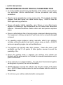
BEFORE WORKING ON ANY VEHICLE, PLEASE READ THIS!
♦ To avoid possible personal injury and damage to the vehicle, please refer to
the appropriate vehicle manufacturer's service procedures and safety
instructions.
♦ Objects can be propelled by moving engine parts. These objects and high
pressure fluids and liquids can cause serious injury. ALWAYS wear an
ANSI approved eye protection.
♦ Ensure all sparks, lighted cigarettes, open flames, or any other device
capable of producing a high temperature are not utilized near automotive
batteries. Automotive batteries contain sulfuric acid and produce explosive
gases.
♦ Ensure a safe distance from all moving engine components during servicing.
Test equipment, clothing, and parts of your body can be seriously damaged
or injured.
♦ An operating engine produces carbon monoxide, which is an odorless,
colorless, poisonous gas that can lead to serious injury or death. ALWAYS
service an operating engine in a well-ventilated area.
♦ Fuel systems are typically under high pressure. Ensure the area is well
ventilated and free of all sparks or other ignition sources to avoid the
possibility of fire.
♦ Ensure the parking brake is engaged, the vehicle’s drive wheels are
blocked, and the gear selector is in neutral for manual transmissions and in
park for automatics.
♦ Never set tools on a vehicle’s battery. You may short the terminals together
causing harm to yourself, the tools or the battery.
♦ NEVER attempt to operate this software and drive the vehicle at the same
time. ALWAYS have another person to use the software while the vehicle is
being driven.
♦ Do not leave your vehicle unattended while running tests.
4
II. SOFTWARE LICENSE AGREEMENT
PLEASE READ ALL OF THE TERMS OF THIS AGREEMENT PRIOR TO INSTALLING THE SOFTWARE.
BY INSTALLING THE SOFTWARE, YOU ACCEPT THE TERMS AND CONDITIONS OF THIS AGREEMENT.
1. Grant of License: In consideration of payment of the LICENSE fee, which is a part of the price you paid for this product, EASE
Simulation, Inc. ("EASE"), as Licenser, grants to you, the LICENSEE, a non-exclusive right to use and display this copy of an EASE
Software Program (hereinafter to "Software") on a single COMPUTER, (i.e., with a single CPU) at a single location. "Software" includes all
software that resides on the included media, any installed software/files from this media, and all firmware and microcode within the
accompanying Hardware, and all printed materials. “Hardware” includes the interface hardware, data logger, and any and all other hardware
that may be used with the Software. If the single computer on which you use the software is a multi-user system, the License covers all
users on that single system. EASE reserves all rights not expressly granted to LICENSEE.
2. Ownership of Software: As the LICENSEE, you own the magnetic or other physical media on which the Software is originally or
subsequently recorded or fixed, but EASE retains title, ownership and copyrights of the Software recorded on the original disk copy(ies) and
all subsequent copies of the Software or derivative works, regardless of the form or media in or on which the original and other copies may
exist. This license is not a sale of the original Software or any copy.
3. Copy Restrictions: This Software and the accompanying written materials are copyrighted. Unauthorized copying of the Software,
including Software that has been modified, merged, or included with other software, or the written materials is expressly forbidden. The
Firmware or Microcode within the Hardware contains copyrighted material, trade secrets and other proprietary material and may not be
copied under any circumstances. You may be held legally responsible for any copyright infringement that is caused or encouraged by your
failure to abide by the terms of this License. Subject to these restrictions, you may make one (1) copy of the Software (except the Firmware
and Microcode) for backup purposes. Any permitted copies must include the same proprietary and copyright notices as were affixed to the
original. You may not copy the disk(s), disk contents, the firmware or microcode or accompanying printed material to sell or distribute to
others.
4. Use Restrictions: As the LICENSEE, you may physically transfer the Software from one computer to another provided that the Software
is used on only one computer at a time. You may not electronically transfer the Software from one computer to another over a network. You
may not distribute copies of the Software or accompanying written materials to others.
The Software and Hardware contains copyrighted material, trade secrets and other proprietary material. In order to protect them, and except
as permitted by applicable legislation, you may not , translate, reverse engineer, disassemble, decompile or otherwise reduce the Software
or Hardware to a human-perceivable form. You may not modify, network, rent, lease, loan, distribute or create derivative works based upon
the Software or Hardware in whole or in part.
5. Transfer Restrictions: You may not transfer this Software to anyone else unless (1) the recipient accepts all of the terms of this License
agreement, and (2) you permanently transfer all copies of the Software and written materials and destroy all other complete or partial copies
of the Software and written materials residing on any medium or storage device.
6. Termination: This License is in effect until terminated. You may terminate this License at any time by properly transferring or destroying
all copies of the Software and accompanying written materials in your possession. This License will terminate immediately without notice
from EASE Simulation, Inc. if you fail to comply with any provision of this License.
7. Export Law Assurances: You agree and certify that neither the Software nor any other technical data received from EASE, nor the
direct product thereof, will be exported outside the United States except as authorized and as permitted by the laws and regulations of the
United States. If the Software has been rightfully obtained by you outside of the United States, you agree that you will not re-export the
Software nor any other technical data received from EASE, nor the direct product thereof, except as permitted by the laws and regulations of
the United States and the laws and regulations of the jurisdiction in which you obtained the Software.
8. U.S. Government Provision: This Software and related written materials were developed at private expense. No portion of this
software or documentation is in the public domain and in all respects is proprietary to EASE Simulation, Inc. If you are acquiring the
Software on behalf of any unit or agency of the United States Government, the following provisions apply. The Government agrees: (1) if
the Software is supplied to the Department of Defense (DOD), the Software is classified as "Commercial Computer Software" and the
government is acquiring only "restricted rights" in the Software and it's related documentation as that term is defined in the DOD Supplement
to the Federal Acquisition Regulations, Clause 252.227-7013(c)(1) and (2) if the Software and related documentation is supplied to any unit
or agency of the United States government other than DOD, the Government rights in the Software and its related documentation will be as
defined in Clause 52-227-19(c)(2) of the FAR or, in the case of NASA, in Clause 18-52.227-86(d) of the NASA Supplement to the FAR and
(3) Use, duplication, or disclosure by the government is subject to restrictions as set forth in subparagraph (c)(1)(iii) of the Rights in
Technical Data and Computer Software clause 52.227-7013. Manufacturer is EASE Simulation, Inc., State Route 492 Box 3011, New
Milford, PA 18834.
9. Controlling Law and Severability: This License and Limited Warranty shall be governed by and construed in accordance with the laws
of the United States and the Commonwealth of Pennsylvania, as applied to agreements entered into and to be performed entirely within
Pennsylvania between Pennsylvania residents. If for any reason a court of competent jurisdiction find any portion of this License, or portion
thereof to be unenforceable, that provision of the License shall be enforced to the maximum extent permissible so as to effect the intent of
the parties, and the remainder of this License shall continue in full force and effect.
10. Complete Agreement: This License constitutes the entire agreement between the parties with respect to the use of the Software and
related documentation, and supersedes all prior or contemporaneous understandings or agreements, written or oral, regarding such subject
matter. No amendment or modification of this License will be binding unless in writing and signed by a duly authorized representative of
EASE Simulation, Inc.
Should you have any questions concerning this Agreement, please call or write the manufacturer:
Simulation, Inc., State Route 492 Box 3011, New Milford, PA 18834 USA 570-465-9060.
5
EASE
III. LIMITED WARRANTY
EASE Simulation, Inc. (EASE) warrants to the original licensee that the diskette(s) on which the software is
recorded be free from defects in materials and workmanship under normal use and service for a period of ninety
(90) days from the date of delivery as evidenced by a copy of your receipt. If a defect in the disk(s) should occur
during this period, you may return the disk to EASE and we will replace the disk(s) without charge. EASE
warrants that for a period of thirty (30) days from the date of delivery to you the licensee, the software shall
materially conform to the specifications defined in pertinent documentation relating thereto (manuals, guides,
exclusion documents, and computer-aided instructions).
EASE does not warrant that the operation of the software will be uninterrupted or error free. Further, EASE
does not warrant or guarantee the use of, or the results of the use of, the software in terms of correctness,
accuracy, reliability, currentness, or otherwise; you rely on the software and results solely at your own risk. The
licensee’s sole and exclusive remedy for failure of the software to materially conform to the specifications
defined in the pertinent documentation is for the licensee to return the software to EASE and notify EASE in
writing of such non-conformity within thirty (30) days of delivery to the licensee. EASE’s sole obligation shall be,
at EASE’s option, within a reasonable time after EASE receives notice of non-conformity, to either provide the
licensee with software, which conforms to the express warranty above, or refund to the licensee the licensee fee
paid therefore. In the event of a refund, this agreement shall be considered terminated and the licensee, if they
have any copies of the software or related materials, shall promptly deliver to EASE and/or destroy all such
copies (including that in memory or data storage apparatus) and warrant in writing to EASE within thirty (30)
days of termination that the licensed software, related materials and all copies thereof have been either returned
and/or destroyed.
To the original purchaser only, EASE warrants the supplied hardware products to be free from defects in
materials and workmanship under normal use for a period of one (1) year from the date of purchase as
evidenced by a copy of the sales receipt. EASE makes no other express warranty on the hardware products.
The purchaser’s sole remedy in the event of a breach of warranty is expressly limited to repair or replacement of
the defective hardware or, if replacement is not possible, a refund of the purchase price. Repair parts and
replacement hardware products will be provided on an exchange basis and will be either reconditioned or new.
All replaced parts become property of EASE. This limited warranty does not cover damage to the products
resulting from misuse, accident, disaster, abuse, negligence, improper maintenance, or modification and/or
repair of the hardware product other than by EASE.
Limitation of Liability - Neither EASE nor its authorized dealer(s) shall be liable for any defect, indirect,
incidental, special, or consequential damages, whether in an action in contract or tort (including negligence and
strict liability), such as, but not limited to, loss of anticipated profits or benefits resulting from the use of this
software and/or hardware product or any breach of any warranty, even if EASE or its authorized dealer(s) has
been advised of the possibilities of such damages. In no event will EASE or its authorized dealer’s liability
exceed the price paid for the product.
Note: Some states do not allow the exclusion or limitation of incidental or consequential damages, so the above
exclusions or limitations may not apply to you.
The information presented in this manual is believed to be accurate. Responsibility for errors, omission of
information, or consequences resulting from the use of this information cannot be assumed by EASE. EASE
retains all rights to make changes to specifications at any time without notice.
How to reach EASE
• Customer Service is available at 888-366-3273 from 9:00 am to 5:00 PM Eastern Standard Time. Please
have your sales order or invoice number available when you call.
• By Telephone: 570-465-9060.
• By Fax: 570-465-9061
• By Mail: EASE Diagnostics State Route 492 Box 3011, New Milford, PA 18834 USA
• By e-mail [email protected]. Our website is located at www.obd2.com
IV. TECHNICAL SUPPORT
If you have questions about the use of this product, first check the relevant portion of the Users Manual, the
EASE Software Help System or refer to the EASE website. If you cannot find the answer in these places, call
our Technical support line at 570-465-9062 ext 252. This support line is answered Monday through Friday from
9:00 am to 5:30 PM Eastern Standard Time. At other times, please leave a message and the call will be
returned. Also, you can e-mail your questions or comments to [email protected].
6
V. PDA REQUIREMENTS
The Scan Tool software supports the following WIN CE/PocketPC devices*.
IMPORTANT: All devices must be running Windows CE 3.0 or higher, Pocket PC 2002 or Pocket PC 2003 and
they must have an SH3, MIPS, StrongARM or X-Scale processor.
HP Jornada Pocket PC- All series
IPAQ pocket PC- All series
Audiovox Maestro Pocket PC’s
Intermec Pocket PC’s
Symbol PDT & PPT Pocket PC’s
Toshiba e570 Pocket PC
Casio Cassiopeia E-200 series, E-125, EG-800 Series, EM 500 Series, IT-70 Series, IT-700 Series
Dell Axim X5
If your PDA is not listed, contact EASE for more information at 888-366-3273. If your PDA is running Windows
CE Version 3.0, Pocket PC 2002 or Pocket PC 2003, has an SH3, StrongARM or X-Scale processor, and has a
serial (9-pin) cable, then it should work with the EASE WIN CE Scan Tool software.
How do I know what version of Windows CE and which processor my PDA is using?
To determine what version of Windows CE and which processor it is using do the following.
1.
From the Start menu choose Settings.
2. Tap on the System tab on the bottom of the Settings Screen.
3.
Tap the About icon.
4. Tap the Version tab on the bottom of the About Screen.
In the About screen the Microsoft Windows CE version is listed and the Processor. If your
PDA is running Windows CE Version 3.0 or Pocket PC 2002 and has an SH3 or StrongARM
processor then it should work with the EASE WIN CE Scan Tool software.
*IMPORTANT: In addition to a supported device, the Scan Tool software requires a serial (9pin) cable to connect the PDA Vehicle Interface to the WIN CE/Pocket PC Device. If you use
a docking cradle or a USB cable to transfer files between the desktop PC and WIN
CE/Pocket PC Device, you must purchase a serial cable for your device in order to use the
Scan Tool software to connect to a vehicle. This cable is not the same for all manufacturers
or models. You must purchase the cable specified for your device. A list of supported WIN
CE/Pocket PC models and their correct serial cable part numbers is listed in Appendix A.
7
VI. STEP-BY-STEP SOFTWARE INSTALLATION INSTRUCTIONS
Use the following instructions to install the EASE Scan Tool software on your WIN
CE/PocketPC device.
1. Connect the CE/POCKET PC device to the PC. The device must be powered on.
IMPORTANT: You must have ActiveSync installed on your PC. Microsoft ActiveSync is used to
transfer files from your PC to your hand held device. This software is included when you purchase a
CE/Pocket PC device.
2. Place the EASE software installation CD in your desktop PC CD-ROM drive. The CD will start automatically.
NOTE: If the CD does not start automatically, double-click the My Computer icon on the Windows desktop.
Locate the CD-ROM drive in the window, double-click the drive letter to display the contents of the CD, and the
double-click SETUP.EXE.
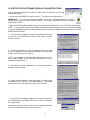
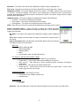
3. In this screen the installation software will determine which type
of processor your CE/Pocket PC device has. Select the Next
button to continue.
4. Choose the products you wish to install and select the Install
button. In addition to the PocketScan Application, you must select
at least one of the Scan Tool Versions.
NOTE: (Not Installed) is displayed after the product name if it is
not currently installed on the connected CE/Pocket PC device.
(Installed) is displayed if it is.
5. The Welcome Screen is displayed next. Press the Next button
to continue with the install.
6. Please read the Software License Agreement. This agreement
can also be found in Section II of the User’s Manual. If you accept
the terms of the License Agreement, select Yes to continue.
7. At this point, the installation program has enough information to
start copying files to the CE/Pocket PC device. Press Yes to begin
the copy process.
Each program that you chose to install will be installed individually.
Press Yes to begin the copy process for each one.
8
8. At this time, please check the CE/Pocket PC device to see if
there are any additional steps that are necessary to complete the
installation.
NOTE: If more than one program is being installed, you will be
returned to step 7.
9. At this time, installation is complete. Select OK to close the
installation software.
10. To start the EASE Software, pick PocketScan from the Start
Menu on your CE/Pocket PC device.
IMPORTANT: BEFORE YOU CAN USE THE EASE SCAN TOOL SOFTWARE TO CONNECT TO A
VEHICLE, YOU MUST CALL EASE AT 888-366-EASE (3273) FOR A PRODUCT ACCESS CODE.
See the next section for more information on product access codes.
VII. PRODUCT ACCESS CODES
IMPORTANT: BEFORE YOU CAN USE THE EASE SCAN TOOL SOFTWARE TO CONNECT TO A
VEHICLE, YOU MUST CALL EASE AT 888-366-EASE (3273) FOR A PRODUCT
ACCESS CODE.
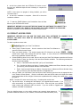
To obtain a product access code:
Start your Scan Tool Software.
1.
2. Select [View] \ Product Access… from the menubar of the Scan Tool Software to
open the Product Access Screen.
3. Enter your Serial Number. This number begins with CE- followed by an 8-digit
number with a dash mark inserted after the first 4 digits. It can be found on a
label on the installation software CD case.
4. Contact EASE by phone, fax or email. Be sure to have your Scan Tool Software opened to the Product
Access Screen or have your Security Code and Serial Number available. The software generates the
Security Code automatically.
a. Phone – Call EASE at 888-366-EASE (3273) or 570-465-9060.
b. Fax – Send a fax listing your Name, Company Name, Address and Phone Number along with
your Security Code and Serial Number to 570-465-9061.
c.
Email - Send an email listing your Name, Company Name, Address and Phone Number along
with your Security Code and Serial Number to [email protected].
5. After you obtain your Verification Code and Access Code, carefully type them into the appropriate box
in the Product Access Screen. Both the verification code and access code are 8 digits with a dash
mark inserted after the first 4 digits. All letters are capitalized and 0 is always the number zero – never
the letter O.
NOTE: The letter O is never used in any entry. It is always the number zero.
6. Tap the Ok button. A message box will display if your upgrade was successful. If you
were unsuccessful, try re-entering your access code. Also verify that your software
serial number and verification code are correct. If you are unable to upgrade your
software, call EASE for assistance.
Tap the Add-Ons button to view which products you currently have access to. To
purchase additional features for your software, contact EASE at 888-366-EASE (3273).
9
How do I enter text on my WIN CE/Pocket PC device?
To enter text in the Product Access Screen – tap in the entry box that you want to enter
text in; the on-board keyboard will be displayed automatically. Tap the characters that
you want to enter and then tap the keyboard icon to close the keyboard.
If the keyboard does not open automatically, tap the keyboard icon that is displayed on the bottom right
hand side of the Product Access software screen. The on-screen keyboard will be displayed. Tap the icon
again to close the keyboard.
VIII. UNINSTALLING THE SOFTWARE
To uninstall the Scan Tool Software from the CE/Pocket PC device
1. Connect your CE/POCKET PC Device to your PC. The device must be powered
on.
IMPORTANT: You must have ActiveSync installed on your PC. Microsoft ActiveSync is used to transfer files
from your PC to your hand held device. This software is included when you purchase a CE/Pocket PC device.
2. Place the EASE software installation CD in your PC CD-ROM drive. The CD will start automatically.
NOTE: If the CD does not start automatically, double-click the My Computer icon on the Windows desktop.
Locate the CD-ROM drive in the window, double-click the drive letter to display the contents of the CD, and the
double-click SETUP.EXE.
3. In this screen the installation software will determine which type of processor
your CE/Pocket PC device has. Select the Next button to continue.
4. Choose the products you wish to uninstall. Then tap the Remove button.
NOTE: (Not Installed) is displayed after the product name if it is not currently
installed on the connected CE/Pocket PC device. (Installed) is displayed if it is.
IX. VEHICLE REQUIREMENTS
This product is designed to work with all OBD II compliant vehicles.
•
•
1996 or newer OBD II Compliant Vehicle (Includes All Domestic, Asian and European Vehicles)
Some 1994 and 1995 vehicles are OBD II Compliant
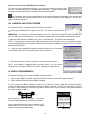
For your vehicle to be OBD II compliant it must have a 16 pin DLC under the dash and the vehicle Emission
Control Information label must state that the vehicle is OBD II compliant. This label is located on the inside of
the hood on most vehicles. An example of this label is shown below. Note the last line of the label states that
the vehicle is OBD II certified.
Vehicle Emission
Control Information
(Figure Above) DLC- Data Link Connector - a 16 position
connector located under the driver side dash of most vehicles.
(Figure to Right) Vehicle Emission Control Information Label located inside the hood of most vehicles. Use it to identify
whether or not the vehicle is OBD II certified.
This vehicle is equipped with electronic
c ontrol syst em s.
Engine idle
speed, idle mixture and ignition timing
are not adjustable. See Powertrain
Control/Emissions Diagnosis Manual
for additional information.
This vehicle conforms to U.S. EPA and
California regulations applicable to 1998 model
year new LEV passenger cars certified for sale
in California. HSC 39037.05 Low Emission
Motor Vehicle. OBD II Certified.
OBD II Certified
10
X. SETUP PROCEDURES
NOTICE
THIS PRODUCT IS DESIGNED TO OPERATE AT A VEHICLE’S NORMAL BATTERY VOLTAGE: 11-15
VOLTS DC. ANY OTHER VOLTAGE MAY DAMAGE THE EASE POCKETSCAN TOOL UNIT!
This section includes the following:
1. What comes with an EASE PDA Scan Tool?
2. Step by step instructions for setting up the EASE PDA Scan Tool
a. Connecting EASE PDA Scan Tool to a WIN CE/Pocket PC device
b. Connecting the EASE PDA Scan Tool to the Vehicle
c. Using the EASE PDA Scan Tool Software to scan vehicle data.
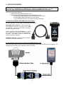
1.0 What Comes With An EASE PDA Scan Tool Package?
An EASE PDA Scan Tool Package is provided with the following:
EASE PDA Vehicle Interface – Black interface box
with a DB25 pin connector on one end and a DB9
pin connector. This unit can be used to connect to
all OBD II compliant vehicles.
Vehicle Interface Cable (CABLE-OBD II) – A cable
with an OBD II connector on one end and a DB25 on
the other. This cable is used to connect to the
vehicle’s diagnostic connector.
Installation Software – Software used to install the
PDA Scan Tool on the PDA Device.
2.0 Step-By-Step Instructions For Setting Up The EASE PDA Scan Tool
The EASE PDA Vehicle Interface must be connected between the vehicle and PDA device to operate. The
following sections explain how to make the proper connections.
11
2.1 Connecting the EASE PDA Vehicle Interface to a WIN CE/Pocket PC Device
Connect the PDA’s Serial Cable* to the communication port on the WIN CE/Pocket PC device. Connect the
other end to the 9-pin “PDA” connector on the PDA Vehicle Interface.
WIN CE/Pocket PC Device
WIN CE/Pocket PC Serial Cable
*To connect the EASE PDA Vehicle Interface to the WIN CE/Pocket PC Device, a serial
cable that connects to your WIN CE/Pocket PC Device is required. If you use a docking
cradle or a USB cable to transfer files between the desktop PC and WIN CE/Pocket PC
Device, you must purchase a serial cable for your device in order to use the Scan Tool
software to connect to a vehicle. This cable is not the same for all manufacturers or models.
You must purchase the cable specified for your device. A list of supported WIN CE/Pocket
PC models and their correct serial cable part numbers is listed in Appendix A.
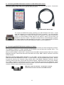
2.2 Connecting the EASE PDA Vehicle Interface to a Vehicle
To connect the PDA Vehicle Interface to the vehicle, you must first locate the vehicle’s diagnostic connector.
The diagnostic connector is a 16-pin connector and is referred to as the Data Link Connector (DLC). This
connector supplies power to the PDA Vehicle Interface.
After you have located the vehicle’s DLC, connect one end of the OBD II Vehicle Interface Cable to the vehicle's
diagnostic connector. Connect the other end of the cable to the 25-pin “OBD II Vehicle” connector on the PDA
Vehicle Interface.
Where do I find the vehicle’s DLC connector? On most OBD II vehicles the diagnostic connector is located
under the driver’s side dashboard in full view. In some vehicles it may be recessed behind a panel. Remove
this panel for access to the connector. Other vehicles have a cap labeled “Diagnostic Connector” over the
connector. Remove this cap to connect the PDA Vehicle Interface. Replace this cover when you are finished.
To be OBD II compliant: if the diagnostic connector is not located under the driver's side dashboard, a label
should be placed there to notify the owner where it is located. If you are unable to find the diagnostic connector,
consult the vehicle’s service manual for the exact location.
OBD II DLC- Data Link Connector - A 16-position connector
located under the driver side dash of most OBD II vehicles.
12
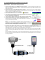
2.3 Using the EASE PDA Scan Tool Software to Scan Vehicle Data
SAFETY FIRST!!!
Review Section I. Safety Precautions.
1. Connect the PDA Device to the EASE PDA Vehicle Interface. Connect the PDA’s Serial Cable to the
serial port of the WIN CE/Pocket PC device. Connect the other end to the 9-pin “PDA” connector on the
PDA Vehicle Interface.
2. Connect the vehicle to the EASE PDA Vehicle Interface. Connect one end of the Vehicle Interface
Cable to the vehicle's diagnostic connector. Connect the other end of the cable to the 25-pin “OBD II
Vehicle” connector on the PDA Vehicle Interface.
3. Start the WIN CE/Pocket PC Scan Tool Software.
4. In the Vehicle Communications Screen select the make of the vehicle that
you are connecting to in the Make box.
5. Turn the vehicle’s ignition switch to the “ON” position or start the vehicle.
6. Tap the Connect button in the Vehicle Communications Screen. If the
Connect button is not selectable, verify that the Cable Status is “Connected”. If
it is not, verify all cable connections.
NOTE: If the Cable Status is “Connected” and the Connect button is not
selectable, you may not have permission to access this data. If you have an
access code, enter it on the Product Access screen. If you do not have an
access code, contact EASE Diagnostics for more information.
7. At this time the software will connect to the vehicle and begin the communication process. The
status of this connection is shown in Tool Status. If the software successfully linked to the vehicle, the
Cable Status will be “Connected” and the Tool Status will be “Scanning Data…”.
If the software did not link, check all cable connections, make sure the ignition is ON, and that the OBD II
connector is powering the EASE PDA Vehicle Interface. Also check that the PDA device battery power is
not low.
Once the software is scanning data, you can view the data parameters in grid, graph or meter format, look
at DTCs, I/M monitors and O2 Test Results. See the Section XII. Software Operation for more information
on using the software.
13
XI. AUTOMOBILE ON-BOARD COMPUTERS AND DIAGNOSTIC TROUBLE CODES
The following section provides information on
1. OBD II
2. Automobile on-board computers
3. The Malfunction Indicator Lamp (MIL)
4. Freeze Frame Data
5. Diagnostic Trouble Codes (DTC)
6. Inspection and Maintenance (I/M) Readiness Monitors
1.0 OBD II
Federal law required all vehicle manufacturers to meet On Board Diagnostics, Second Generation
or
OBD II standards by 1996. In order to meet this standard, the automobile’s on-board computer must monitor
and perform diagnostic tests on vehicle emissions to ensure that the vehicle is operating at an acceptable
(legal) emission level. The maximum allowable emission level is set by the Federal Test Procedure (FTP).
All 1996 and newer passenger vehicles are OBD II compliant. All OBD II vehicles have the same 16 pin
diagnostic connector or DLC. This eliminates the need to have a manufacturer specific connector to connect to
your vehicle. (Some 1994 and 1995 vehicles have this connector, however, this does not mean that the vehicle
is OBD II compliant. )
2.0 Automobile On-board Computers
Automobile on-board computers control engines, transmissions, brakes, traction and many other components.
These computers have several names and acronyms depending upon the manufacturer and components they
control. The most common name is PCM or Powertrain Control Modules. Other examples are Body Control
Modules (BCM), Transmission Control Modules (TCM), Electronic Brake Control Module (EBCM) and Air
Conditioning Control Module (ACM).
A variety of sensors, such as the oxygen sensor, throttle position sensor and manifold air temperature sensor,
provide information to the on-board computer regarding the vehicle’s engine operating conditions. Air
Conditioning systems, vehicle air bags, and anti-lock brake systems also report to on-board computers.
On-board computers have a built in self testing system called self-diagnosis which means the on-board
computer will monitor many or all of the vehicle’s sensors and controlled devices for proper operation. A
diagnostic trouble code or DTC is detected and set when one of the monitored devices is not functioning
properly. This malfunction is stored into the on-board computer’s memory as a DTC number that is related to a
specific sensor or other problem. The computer can later be accessed using the EASE software or other scan
tools and code reading devices to obtain the codes stored in the on-board computer memory.
3.0 Malfunction Indicator Lamp (MIL)
The Malfunction Indicator Lamp (MIL) is located in the instrument panel on the dashboard and is either a red or
yellow labeled lamp. The MIL is normally off and will illuminate if a system or component either fails or
deteriorates to the point where the vehicle emissions could rise 1.5 times above the FTP set emissions level.
4.0 Freeze Frame Data
When the first emissions related powertrain DTC becomes stored, the PCM will capture (save) a block of
current engine parameters. This list of parameters is called Freeze Frame Data and consists of a fixed list of
parameters. For vehicles, which do not support all parameters, only the applicable ones are stored. When
DTCs are cleared, the Freeze Frame Data is cleared from the vehicle’s PCM.
14
5.0 Diagnostic Trouble Codes or DTCs
In the past malfunction code numbers varied between manufacturers, years, makes and models. OBD II
requires that all vehicle manufacturers use a common Diagnostic Trouble Code or DTC numbering System.
There is a generic DTC listing that all manufacturers must use. Since the generic listing was not specific
enough, most manufacturers came up with their own DTC listing, which are called manufacturer specific codes.
Both generic and manufacturer specific codes are 5 digits.
The first digit is a letter, which identifies the function of the device, which has the fault. This digit can be either
P
Powertrain
B
Body
C
Chassis
U
Network or data link code
The second digit is either a 0 or 1 and indicates whether the code is
generic or manufacturer specific.
0
Generic
1
Manufacturer Specific
The third digit represents the specific vehicle system that has the fault.
Listed below are the number identifiers for the powertrain system.
1
2
3
4
5
6
7
8
Fuel and Air Metering
Fuel and Air Metering (Injector Circuit Malfunctions Only)
Ignition System or Misfire
Auxiliary Emission Control
Vehicle Speed Control and Idle Control System
Computer and Auxiliary Outputs
Transmission
Transmission
The last two digits indicate the specific fault index.
On OBD II vehicles there are two different types of DTCs: Stored and Pending. For a DTC to become Stored,
certain malfunction conditions must occur. The condition(s) required to Store a code are different for every DTC
and vary by vehicle manufacturer. In order for some DTCs to become Stored, a malfunction condition has to
happen more than once. If the malfunction conditions are required to occur more than once, the potential
malfunction is called a Pending DTC. The DTC remains Pending until the malfunction condition occurs the
required number of times to make the code Stored. If the malfunction condition does not occur again after a set
time the Pending DTC will be cleared.
6.0 OBD II Inspection and Maintenance (I/M) Readiness Monitors
A monitor is a piece of software in one of the vehicle’s on-board computers that has the job of monitoring a
specific piece of the engine. There are two types of monitors: continuous and non-continuous. A continuous
monitor runs continuously during vehicle operation. A non-continuous monitor requires enabling criteria to
make it run. Some examples of enabling criteria are vehicle acceleration/deceleration to a certain speed,
engine temperature and driving the vehicle at a certain speed for a period of time.
For OBD II vehicles, there is a fixed list of 11 monitors: 3 continuous and 8 non-continuous. The 11 monitors
are not applicable for all vehicles. The Inspection & Maintenance screen of the software lists the availability and
status of your vehicles monitors. In order to pass an emission inspection all of the supported monitors must be
completed.
The Continuous Monitors are:
•
Misfire
•
Fuel System
•
Components
•
•
•
Secondary Air System
A/C System
EGR System
•
•
Oxygen Sensor
Oxygen Sensor Heater
The Non-Continuous Monitors are:
•
•
•
Catalyst
Heated Catalyst
Evaporative System
15
XII. SOFTWARE OPERATION
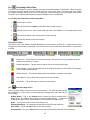
1.0 Software Toolbar
Displayed at the bottom of the software screens, the Toolbar provides a quick and handy way to navigate. Just
tap on the screen you wish to view. A description of each toolbar icon is given below followed by the section
number where more information on the screen can be found.
Vehicle Communications – Section 2.0
Real Time Data Grid - Section 3.0
Meters – Section 4.0
Graphs – Section 5.0
Diagnostic Trouble Codes – Section 6.0
Freeze Frame – Section 7.0
Oxygen Sensor Test Results – Section 8.0
Inspection and Maintenance Monitors – Section 9.0
Recording Data – Section 10.0
Playing Back Recordings - Section 11.0
Reset Scan Buffer – Section 12.0
Preferences – Section 13.0
16
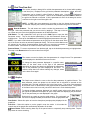
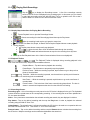
2.0
Vehicle Communications
The Vehicle Communications Screen displays information on the status of the software
connection with the vehicle. To connect to the vehicle, tap on the Connect button. During
the communication initialization the software will do the following:
•
•
•
•
•
•
Determine if there are multiple modules on the vehicle bus
Determine all the capabilities of the vehicle
Obtain I/M Readiness Status data
Obtain Oxygen Sensor Location and O2 test data
Obtain any DTCs if present
Obtain Freeze Frame data if present
Cable Status
• Connected is displayed if the EASE PDA Vehicle Interface is properly connected to the vehicle and
PDA.
• Disconnected is displayed if the EASE PDA Vehicle Interface is not connected to the vehicle and PDA.
Interface - This is the OBD II communication interface type of the current connected vehicle.
• ISO 9141-2 - International Standardization Organization
• PWM - Pulse Width Modulation
• VPW - Variable Pulse Width
• ISO 14230 (KWP 2000) – Key Word Protocol 2000
Tool Status - The current status of the tool is displayed here.
• Browse: The software is currently not communicating with the vehicle.
• Scanning Protocols: The software is determining the communication protocol of the vehicle.
• Getting Capabilities: The software is communicating with and determining the capabilities of the
vehicle.
• Scanning Data: The software is communicating with and receiving data from the vehicle.
• Play Back: The software is currently replaying previously recorded vehicle data.
Make - The Make of the vehicle can be selected here. This information does not have to be entered to connect
to an OBD II vehicle. However, the correct Make must be selected to access enhanced data and to ensure the
proper diagnostic trouble code description is displayed.
Module # - This is the bus address of the vehicle’s on-board computer. The PID (Parameter Identification)
count is also displayed here, which is the number of supported parameters for the on-board computer.
Sometimes an OBD II vehicle will have more than one controller (on-board computer). If multiple controllers are
detected during the initial communications scan, the software will list them in the Module # drop down box. The
User can then select which controller they want to scan by selecting the desired controller from the drop down
box. The software will default to the controller that contains the highest PID count. Normally the Controller
Address with the highest PID Count is the engine controller and the second highest is the transmission
controller.
DTC Alert - The DTC Alert is flashed when a DTC has been detected on the vehicle. Tap on this button to go
to the DTC Screen to view the active DTC(s).
Connect/Disconnect button - Tap on this button to connect or disconnect communications from the software
to the vehicle. This button is only selectable when the Cable Status is Connected.
NOTE: If the Cable Status is “Connected” and the Connect button is not selectable (grayed out), you may not
have permission to access this data. If you have an access code, enter it on the Product Access screen. If you
do not have an access code, contact EASE Diagnostics for more information.
2.1 Vehicle Communications Lost
The Vehicle Communications Lost screen is displayed whenever communications have been
lost to the vehicle. Check all cable connections, ensure the ignition key is on or the vehicle is
running, and double check that the vehicle is OBD II compatible. Also, be sure that the battery
power of the PDA device is not low. Low battery power could cause erratic and unreliable
communication with the vehicle.
17
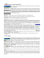
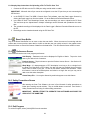
3.0
Real Time Data Grid
This screen contains a data grid for vehicle data parameters to be viewed while updating
in real time (live). Displayed in the grid are the parameter descriptions, values, and units.
Preferences
Parameters can be viewed in either English or Metric units. Use the
Screen to change the unit system. One to all the available parameters can be added to
the grid to be scanned or recorded. If all the parameters do not fit in the data grid, use the
scroll bar on the right to scroll through the list.
NOTE: In OBD II the more parameters you select to view, the slower the data updates.
For the best sampling rate, limit the parameters that you add to the grid to be scanned.
Reorder Buttons - The red arrows are used to reorder the parameters in the
data grid. Select the parameter that you want to move by tapping it. Then tap on the red
up or down arrow to move the highlighted parameter to the desired position.
Add Button - To add a parameter to the grid, tap on the Add button to open the Add
Parameter screen. Tap on the desired parameter(s) in the Add Parameter Screen to
highlight them. Then tap on the Add button to add the highlighted parameters to the grid.
NOTE: If you want to add enhanced parameters to the grid, tap on the down arrow at the
top of the screen to select an enhanced parameter listing. The correct vehicle Make must
be selected in the Vehicle Communications Screen and you must have permission to
access this data. See Section VII Product Access Codes for more information.
Remove Button - To remove a parameter from the data grid, tap on the desired parameter(s) to highlight them.
Then tap on the Remove button to remove them from the grid.
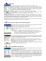
4.0
Meters
The meters are used to display the data parameters in a larger format. Two parameters
can be displayed on the Meters screen at one time.
To change the data parameter displayed in a specific meter,
select on the down arrow to the right of the parameter
description to open a drop down box displaying the parameters.
Tap on the parameter you want displayed in the meter. To
close the drop down box without making any changes, select
on the down arrow again.
5.0
Graphs
The Graph screen allows the user to view the data parameters in graphical format. The
data parameter values are plotted on the vertical axis in reference to seconds on the
horizontal axis. The bold vertical blue line is the frame cursor. The value of the parameter
at the frame cursor is shown above each graph beside the parameter name. The position
of the frame cursor can be moved, just select it and move it to the desired position.
To change the data parameter displayed in a specific graph, select on the down arrow to
the right of the parameter description to open a drop down box displaying the parameters.
Tap on the parameter you want displayed in the graph.
Double click on a graph to open the graph options. For each graph, you
can select to display the data points and/or to have the graph auto size.
Data Points - Select this option to have the data points (sample points) displayed in the
graph line.
Auto Size – Select this option to put the graph in auto size mode. In this mode the
vertical axes of the graphs are automatically adjusted to fit the data.
Pause Button -While scanning data, tap on the pause button to temporarily stop scanning data. Tap the
play button to resume scanning.
18
6.0
Diagnostic Trouble Codes (DTC)
The Trouble Codes Screen displays the vehicle’s MIL Status, DTC Count, Stored DTCs
and Pending DTCs.
What is a DTC? Automobile on-board computers have a built in self testing system called
self-diagnosis which means the on-board computer will monitor many or all of the vehicle’s
sensors and controlled devices for proper operation. A diagnostic trouble code (DTC) is
detected and set when one of the monitored devices is not functioning properly. On OBD
II vehicles there are two different types of DTCs: Stored and Pending. See Section XI. for
more information on DTCs.
MIL Status - The status of the vehicle’s MIL (Malfunction Indicator Lamp) is displayed here.
DTC Count - Displays the total number of emission related DTCs currently stored in the vehicle.
Stored DTCs - All of the vehicle’s stored DTCs are listed in this section.
Pending DTCs - All of the vehicle’s pending DTCs are listed in this section.
NOTE: The Make setting in the Vehicle Communications screen is used for determining the description of
manufacturer specific DTCs. If manufacturer specific DTCs are displayed (P1XXX), the correct Make must be
selected in the Vehicle Communications screen to ensure that the correct description is being displayed in the
Trouble Code grids. See section 2.0 Vehicle Communications for more information on selecting the vehicle’s
Make. See Section XI. for more information on DTCs.
Clear DTCs Button - Tap on this button to clear (erase) the Stored and Pending DTCs, Freeze
Frame Data, Oxygen Sensor Test Data, and Inspection and Maintenance Monitors from the
vehicle’s on-board computer. After tapping this button, a confirmation screen is displayed to
inform the user which vehicle information will be erased. Make sure that the vehicle’s ignition
key is in the ON position and the vehicle’s engine is not running. For some vehicles unless
these conditions are met the DTCs will not be cleared. Tap on the Yes button to continue with
the clearing process or No to cancel.
Freeze Frame Button - Tap on this button to display the vehicle’s Freeze Frame data. See
section 7.0 Freeze Frame for more information.
DTC Library Button - Tap on this button to display the DTC Library screen. See the section 6.1 for more
information.
6.1 DTC Library
The DTC Library Screen allows you to look up the description for a DTC Number. Both
generic and manufacturer specific DTCs can be looked up. Use the DTC Library button in
the DTC Screen or View\DTC Library from the menubar to open the DTC Library. See
Section XI. for more information on DTCs.
Make - Tap on the arrow to the right of the box to open a drop down box listing vehicle
makes. It is important that you select the correct make if you are looking up a
manufacturer specific DTCs (P1XXX) because manufacturer specific DTC’s descriptions
may differ between manufacturers. Choose Generic as the make to look up generic
(P0XXX) codes.
Search - Type in a DTC number, word that you are looking for or start of a word or DTC in
this box and then tap on the Search button. The results of the search will be displayed in
the grid below.
NOTE: Delete the text you entered in the Search box and then select the Search button to return to the original
look up.
DTC Code and Description grid - The DTC number and corresponding description is displayed in the grid.
The scroll bar to the right of the DTC grid can be used to manually scroll through the DTC and description list.
The scroll bar on the bottom of the grid can be used to move the grid left and right in order to see the complete
description.
19
7.0
Freeze Frame
The Freeze Frame Data Screen displays the vehicle’s freeze frame data, if any.
What is Freeze Frame? In OBD II vehicles, when the first emissions related powertrain
DTC occurs, the PCM will snapshot (save) a block of current engine parameters. This list
of parameters is called Freeze Frame Data and consists of a fixed list of parameters.
Vehicles may not support every parameter on the fixed list.
NOTE: When DTCs are cleared, the Freeze Frame data is also cleared.
Freeze Frame DTC - The DTC that caused the freeze frame is displayed here. N/A is
displayed if there is no Freeze Frame data present on the vehicle.
Description and Value Grid - The grid displays a description of the freeze frame parameters and the values of
the parameters at the time the DTC occurred. The scroll bar to the right of the grid can be used to manually
scroll through the freeze frame parameter list. The scroll bar on the bottom of the grid can be used to move the
grid left and right in order to see the complete descriptions and values.
NOTE: N/A is displayed for all the parameters if there is no Freeze Frame data. If there is Freeze Frame Data,
N/A is displayed for a specific parameter if the vehicle does not support it.
8.0
Oxygen Sensor Locations and Test Results Screens
The Oxygen Sensor Locations Screen shows which Oxygen Sensors (O2) are present
and which ones are not available on the current vehicle.
NOTE: Not all vehicles support Oxygen Sensor Tests.
Bank and Sensor Columns – Lists the oxygen sensor’s bank and sensor location
number.
Status Column – Lists whether or not an oxygen sensor is present on the vehicle.
• Present… is displayed if an Oxygen Sensor is present on the vehicle. Tapping on
this status opens the Oxygen Sensors Test Results Screen for that sensor.
•
Not Available is displayed for locations without an oxygen sensor.
The Oxygen Sensor Test Results Screen shows the on-board oxygen sensor monitoring
test results. Selecting Present… in the Status column of an O2 sensor listed in the Oxygen
Sensor Locations Screen opens this screen.
Description - The available oxygen sensor test parameters are displayed in this column.
Result – The results of the oxygen sensor tests are displayed in this column. A value of
Not Available is listed for tests not supported on the current vehicle.
Ok button- Tap on the Ok button to close the Oxygen Sensor Test Results screen and
return to the Oxygen Sensor Locations screen.
9.0
Inspection and Maintenance Monitors
The Inspection and Maintenance Monitors Screen displays the status of the vehicle’s
inspection and maintenance (I/M) monitors.
What are I/M Monitors? A monitor is a piece of software in one of the vehicle’s on-board
computers that has the job of monitoring a specific piece of the engine. There are two
types of monitors: continuous and non-continuous.
A continuous monitor runs
continuously during vehicle operation. A non-continuous monitor requires enabling criteria
to make it run. Some examples of enabling criteria are vehicle acceleration/deceleration to
a certain speed, engine temperature and driving the vehicle at a certain speed for a period
of time. For OBD II vehicles, there is a fixed list of 11 monitors: 3 continuous and 8 noncontinuous. See Section XI. for more information on monitors.
20
MIL Status - The status of the vehicle’s MIL (Malfunction Indicator Lamp) is displayed here.
DTC Count - Displays the total number of emission related DTCs currently stored in the vehicle.
I/M Monitors Column - This column displays the title of the monitor. For OBD II vehicles, there is a fixed list of
11 monitors: 3 continuous (Misfire, Fuel System, and Comprehensive Component) and 8 non-continuous
(Catalyst, Heated Catalyst, Evaporative System, Secondary Air System, A/C System, Oxygen Sensor, Oxygen
Sensor Heater, EGR System).
I/M Monitor Status - This column displays the availability and status of the I/M Monitor.
• Complete – The monitor is supported and complete
• Not Complete – The monitor is supported and not complete
• Not Supported – The monitor is not supported by the current vehicle
NOTE: When DTCs are cleared, the Inspection and Maintenance Monitors are also cleared.
General Information Button – Select this button to display the General Information
Screen. This screen contains miscellaneous vehicle status information. All vehicles do not
support this information.
MIL Status - The status of the vehicle’s MIL (Malfunction Indicator Lamp) is displayed
here.
DTC Count - Displays the total number of emission related DTCs currently stored in
the vehicle.
General Information Grid - the description and possible Status states of the General
Information grid items are listed below.
OBD Type
•
•
•
•
•
OBD II (California ARB)
OBD (Federal EPA)
OBD and OBD II
OBD 1
Not intended to meet any OBD requirements
Fuel System 1 Status and Fuel System 2 Status
• Open loop (1) - has not yet satisfied conditions to go closed loop
• Closed loop (1) - using oxygen sensor(s) as feedback for fuel control
• Open loop (2) – open loop due to driving conditions (power enrichment, deceleration
enleanment)
• Open loop (3) – open loop due to detected system fault
• Closed loop (2) – closed loop but fault with at least one oxygen sensor - may be using
single oxygen sensor for fuel control
Secondary Air Status
• Upstream of first catalytic converter
• Downstream of first catalytic converter inlet
• Atmosphere/off
Power Take Off
• PTO OFF
• PTO ON
Ok button - Tap on the Ok button to close the General Information screen and return to the I/M Screen.
21
10.0
Recording Vehicle Data
The Scan Tool Software can record, playback and save an unlimited amount of vehicle data. While connected
to a vehicle, tap on the record icon in the bottom tool bar to enter record mode. The bottom part of the toolbar
will change to indicate that the scan tool is in record mode. Saved recording files can be played back with the
CE Scan Tool or exported and played back using the EASE PC Scan Tool Software.
10.1 Step-by-Step Instructions for Recording Data
1.
Connect to the vehicle.
2.
Go to the Data Grid and Add the parameters that you want to record.
Tap the record icon to enter record mode (Important: The software is not recording data at this
3.
time)
4.
Tap the record button in the record toolbar to start recording.
5.
Tap the save button to save the recording.
10.2 Record Toolbar
The bottom menu of the software changes depending on what mode the software is in. When the record icon
is tapped, the record toolbar is displayed. The record icon is only selectable when the software is connected to
a vehicle.
Scanning Data Mode
Record Toolbar – Pause Mode
Record Toolbar – Record Mode
Record Icon – Tap on this icon to enter record mode. The record icon is only selectable when the
software is connected to a vehicle.
Record Data Button – Tap this button to start or resume recording vehicle data.
Pause Indicator – This indicator flashes when the software is paused in record mode. The software
is not recording data at this time.
Record Indicator – This indicator flashes when the software is recording vehicle data.
Pause Button - Tap on this button to pause the current recording.
Save Button – Tap on this button to save the record session.
10.3
Save Recording Screen
Tap on the Save button to save the current record session. The Save Recording screen
will be displayed. In this screen you can assign the recording name and enter notes on
the recording.
Default Button – Tap on the Default button to name the current recording with a
default name. The default name consists of the current date and time. To name the
recording otherwise, enter the desired name in the box below the Default button.
Notes – You can enter notes on the record session here.
Existing Recordings – All recordings currently saved in the PDA are listed here.
Save button – Tap on the Save button to save the recording.
Cancel button – Tap on the Cancel button to exit the screen without saving the current recording.
22
11.0
Playing Back Recordings
Tap the
icon to display the Recordings screen. A list of the recordings currently
saved on the CE Device is displayed in the recordings grid. In this screen you can choose
to play back a recording using the WIN CE Scan Tool or to upload it to the PC to view it
with the EASE PC Scan Tool or to share it with other users.
11.1 Step-by-Step Instructions for Playing Back a Recording
1.
2.
Tap the Playback icon to open the Recordings Screen.
Choose a recording from the Recordings grid and then tap the Play button.
After the recording loads, tap the grid, graph or meter icon.
3.
4.
In the Real Time Data Grid, Graph, or Meters Screen tap the Playback button to start playback.
5. During playback,
Tap the pause button to temporarily stop playback.
a.
b.
Use the track bar to scroll forward and back through the recording.
c.
Use the forward and backward arrows to step thru the recording frame by frame.
6.
Tap the End Playback button in the Vehicle Communications Screen to end playback.
11.2 Playback Toolbar
The Playback Toolbar is displayed during recording playback in the
Real Time Data Grid Screen, Graph Screen and Meters Screen.
Playback Button – Tap this button to playback the recording.
Pause Button – Tap this button to temporarily stop the playback.
Previous Frame – While the recording is paused, tap this button to go to the previous
frame of recorded data.
Track Bar – While the recording is paused, use the track bar to quickly scroll forward or
back through the recorded data.
Next Frame – While the recording is paused, tap this button to go to the next frame of
recorded data.
Frame Counter – This is the time of the frame currently being played back. The time is
shown in seconds and represents the time from the start of the recording.
11.3 Recordings Screen
Recordings grid – A list of recordings currently stored on the CE device is displayed in the grid. The Uploaded
column shows the upload status of the corresponding recording. If the recording has never been uploaded to a
PC, the status shows No.
Notes – If any notes were entered when the selected recording was saved, they are displayed in this box.
Play button - Tap on the desired recording and then tap the Play button in order to playback the selected
recording using the WIN CE Scan Tool.
Upload button – The upload button is a feature that allows the CE device to be used as a companion device to
the EASE PC Based Scan Tool. See Section 11. 4 for more information.
Remove button - Tap on the desired recording and then tap the Remove button to delete that recording from
the CE device. Multiple recordings can be selected and deleted at the same time.
23
11.4 Step-by-Step Instructions for Uploading a File To The PC Scan Tool
1. Connect the CE device to the PC COM port using a serial cable or cradle.
IMPORTANT: Microsoft Active Sync cannot be configured to use the PC port that you are connecting the
CE Device to.
2. In the EASE PC Scan Tool OBD II Generic Scan Tool software, open the Data Logger Screens by
clicking the Data Logger icon from the toolbar. Go to the Retrieve Recorded Data tab screen.
3. In the WIN CE Scan Tool Recordings Screen, tap the recordings you want to upload to the PC Scan
Tool and then tap the Upload button. Multiple recordings can be selected and uploaded at the same
time
4. The uploaded recordings will be displayed in the Data Logger’s Retrieve Recorded Data tab screen on
the PC.
5. Recordings can be viewed and saved using the PC Scan Tool.
12.0
Reset Scan Buffer
Tap on the Reset Scan Buffer icon to reset or clear the scan buffer. When the scan tool is scanning real time
vehicle data, it stores previous scan data in a buffer so that the user can quickly review it in the graphs screen.
Select this button to clear all the frames of data from the data buffer. This will reset the frame number counter.
13.0
Preferences Screen
This screen allows the user to set program preferences.
Unit Display – Parameter units can be displayed in English or Metric. Tap on the circle
next to your desired unit of measure.
Product Access – Tap this button to open the Product Access Screen. See Section VII.
for more information.
Word Wrap – If a data parameter or DTC description is too long to fit on a single line in
the Real Time Data Grid or DTC Library, the text will wrap into multiple lines so that the
entire name is shown in the grid. To turn off this feature, deselect this checkbox. When
this feature is turned off all descriptions are limited to a single line and you may not be
able to see the entire description.
Create Dump File – You may be directed by technical support to use this feature.
14.0 Safety Precautions Screen
After starting the Scan Tool Software, the user is first informed of safety precautions to
follow when working around vehicles. Tap on the Ok button to continue. See Section I
Safety Precautions for a listing of vehicle safety precautions.
IMPORTANT: NEVER ATTEMPT TO OPERATE THIS SOFTWARE AND DRIVE THE
VEHICLE AT THE SAME TIME.
15.0 Exit Program
To exit the Program, select [Vehicle]\Exit from the menubar.
24
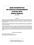
Appendix A – Serial Cable Part Numbers
To connect the EASE PDA Vehicle Interface to the WIN CE/Pocket PC handheld a serial cable is required. If
you use a docking cradle or a USB cable to transfer files between the desktop PC and WIN CE/Pocket PC
Device, you must purchase a serial cable for your device in order to use the Scan Tool software to connect to a
vehicle. This cable is not the same for all manufacturers or models. You must purchase the cable specified for
your device. A list of supported WIN CE/Pocket PC models and their correct serial cable part numbers follows.
If your PDA is not listed, contact EASE for more information at 888-366-3273. If your PDA is running Windows
CE Version 3.0, Pocket PC 2002 or Pocket PC 2003, has an SH3, MIPS, StrongARM or X-Scale processor, and
has a serial (9-pin) cable, then it should work with the EASE WIN CE Scan Tool software.
Supported PDA
HP Jornada 520/540 Series
HP Jornada 560 Series
Compaq IPAQ H 3100 Series
Compaq IPAQ H 3600 Series
Compaq IPAQ H 3700 Series
Compaq IPAQ H 3800 Series
Audiovox Maestro PDA1032C
Intermec Model 70
Intermec 700 Series
Symbol PPT 2800
Serial Cable Part Numbers
F1819A
F1819A
191008-B21
191008-B21
191008-B21
250178-B21
CRS1032B (Serial Cradle)
871-13-030
226-999-001
25-38383-01(Cable only)
CBL2700-100U (Kit)
25-38383-01(Cable only)
CBL2700-100U (Kit)
PA3150U-1ETC
JK-580CA
JK-580CA
JK-580CA
JK-580CA
JK-580CA
JK-580CA
Symbol PDT 8100
Toshiba Model e570
Casio Cassiopeia E-200 Series
Casio Cassiopeia E-125
Casio Cassiopeia EM 500 Series
Casio Cassiopeia EG-800 Series
Casio Cassiopeia IT-70 Series
Casio Cassiopeia IT-700 Series
25