1
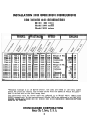
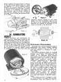
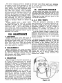
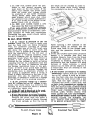
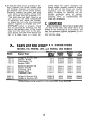
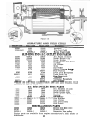
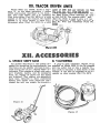
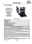
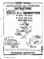
OWNER'S MANUAL
I
.
.
ILMSBRUCTIOFIIS
A. C. GENERATORS
8
Model 700 Series
Model 1800 Series
I
Model 3030 Series
:.-
I
I
MODEL 1800
MODEL 700
If any correspondence is required regarding these generators, always be sure to
furnish the model number and serial number stqmped on the generator nameplate.
WINCHARGER CORPORATION
SIOUX CITY 2, IOWA, U. S. A.
Form SR214, Part No. 20757
I
I
I
1
INSTALLATION A N D OPERATION INSTRUCTIONS
FOR W l N C O A.C. GENERATORS
Model 700 Series
Model 1800 Series
Model 3030 Series
MODEL
WATTAGE
SPEED
ENGINE
700-11
700-12
700-13
700-14
700-1
700-2
700-3
700-4
500
500
500
500
700
700
700
700
3600
3600
3600
3600
3460
3460
3460
3460
1.04
1.04
1.04
1.04
Briggs & Sir.
Clinton
Continental
Lauson
1800-11
1800-12
1800-13
1800-14
1800-15
1800-1
1800-2
1800-3
1800-4
1800-5
1000
1250
1350
1250
1350
1800
1800
1800
1800
1800
3600
3600
3600
3600
3600
3460
3460
2975
3460
2975
1.04
1.04
1.21
1.04
1.21
Briggs&Str.
8 2.5
Clipton
D-1100 3.1
Cushman
M6 3.0
Lauson
T L W 3.0
Wisconsin
ABN 4.6
3030-11
3030-12
3030-X
3030-X
2000
2000
3000
3000
3600
3600
2975
2975
1.21
1.21
B r i g g s & Str.
Briggs&Str.
6
B700
AU7B
RHS
"
2.0
2.0
2.0
2.n
14 5.1
23 8.3
*Nominal wattage is at 1.0 Power Factor. All. units are rated at 115 volts, single
phase, 60 cycles per second. The voltage varies with the speed at which the generator is driven and on the load being used.
The generators only for above units are referred to as Model 700-0, 1800-0, and
3030-0 respectively. In the instructions all Model 1800's are referred to as 1000 watt.
Models 3030A and 303OB are for tractor belt drive-generator
specifications are
same as for 3030-X.
WINCHARGER CORPORATION
Sioux City 2, Iowa, U. S. A.
TABLE O F CONTENTS
I. INTRODUCTION
4
A. Testing
B. Unpacking
C. Guarantee
11. INSTALLATION -------------- ........................
4
A. Portable Use
B. Transfer Switch
C. Flexible Cord
111. F R A M E S - - - - - - - - - - - - - - - - - - - - - - - - - - - - - - - - - - - - - - - -
5
A. 500-1000 Watt Models
1. Engine Base Holes
2. Mounting
3. Belt Tightening
4. Checking Lineup
B. 2000 Watt Models
1. Pulleys
2. Mounting
3. Belt Tightening
4. Checking Lineup
IV. GENERATORS ........................................
A.
B.
C.
D.
6
Design
Performance characteristics
Speed
Overload Protection
V. E N G I N E S - - - - - - - - - - - - - - - - - - - - - - - - - - - - - - - - - - - - - - - -
7
A. Lubrication
B. Manuals
VI. POWER REQUIREMENTS..............................
7
A. Engine Size
B. Altitude-Temperature
VII. USE OF A.C. MOTORS .................................
7
VIII. MAINTENANCE .......................................
8
X. PARTS LIST ...........................................
10
XI. TRACTOR DRIVEN UNITS .............................
10
XII. ACCESSORIES
12
Models 700, 1800,3030
8. INTRODUCTION
etc. directly into the
outlet terminals. The
Each generator is carefully inspected at outlet box is equipped with lock-type rethe factory and "run-in" until the brushes ceptacles which prevent the plugs from
are satisfactorily seated. The unit is then working loose.
To operate permanently c o n n e c t e ~
carefully checked for correct output under
average operating conditions. NO GENER- motors, etc. on a standby basis, provision
ATOR IS SHIPPED UNLESS IT PRO- must be made to prevent the generated
DUCES ITS FULL RA'IYCD CAPACITY, current from "feeding back" into the power
NOR UNTIL IT HAS PASSED RIGID IN- line where it could be a hazard to linemen
other users.
SPECTION TESTS. If uwon installation a and
ALL WIRING IS TO BE DONE IN CONnew generator does noi work properly, FORMANCE WITH -NATIONAL ELECcheck all of the electrical connections and TRICAL CODE AND WITH STATE AND
the generator speed before concluding that LOCAL REGULATIONS.
the generator is not performing satisfactThe conductor from the transfer switch
orily.
to the generator can be made of No. 14 type
w h e n unpacking the machine, be sure to S cord for distance up to 25 feet. Always
inspect it carefully to see that no damages use the twist-lock plug for making these
occilrred in transit. If damages are noted, connections permanently.
notify the transportation company imWhen starting the generator, turn off the
mediately and have them write the load or reduce it. If too many light bulbs
nature of the damages on the freight are left on, the generator may fail to build
bill, so that a claim can be filed if necessary. up voltage.
Each AC generator is guaranteed to be
When a three pole double-throw switch
free from defects in workmanship and is connected to a 115-230 volt system as
material arising in connection with normal shown in Figure 1, the current from the
usage for a period of one year, provided generator is available on both main
that the owner returns his guarantee reg- branches. Any 220 volt appliances connectistration card within 10 days after pur- ed to the circuit will remain inoperative.
chasing the unit. Fill in the information
If the owner wants to use only part of the
requested on the registration- card and electrical circuits, a two-pole, double throw
return it, so the guarantee can be issued switch can be connected i n one or more
to you.
of the branch circuits as shown in Figure 2.
So many different methods of wiring are
encountered in the field that no specific
II. INSTALLATION
transfer switch recommendation can be
given. However, a n electrician who thorwhen using the unit as a portable gen- oughly understands the problem should be
erator, merely plug the power tools, lights, obtained to make the installation.
-
To Load
I- -----
To
Meter
I
(Neutral) II
I_
I
7
I
I
Generator
-
.
I
I
To Load
----I
To
Panel
i
I
(Neutral)
-
I
I
I
I
L ----------1
Figure 2
+
-
To
Generator
Ill. FRAME
All 500 watt and 1000 watt models have
the necessary holes for mounting various
types engines. Figure 3 shows the holes
which are used for mounting the follow.ng types of engines:
Holes
Type Engine
Briggs & Stratton No. 8
Briggs & Stratton No. 6
Continental 7B
Clinton D-1100 (A base)
Clinton B-700 (New base)
Cushman M6
Lauson TLH
Wisconsin ABN
Lauson RSH
Clinton D-1100 ( B base)
Clinton B-700 (Old base)
A
A
A
B
B
C
D
E
F
G
G
D
@
required. The belt should deflect about
?/4" when a pressure of 6 lbs is applied
midway between the pulleys. After the
proper position has been determined, install the three remaining bolts in the generator base and tighten securely. Then recheck the belt lineup using a straight edge
across the beIt pulleys as shown in Figure
5. Finally replace the belt guard.
43
@
0 0 80
63
a@O 0
a
2000 WATT MODELS
8
0
O @
8
80
0
@@
@,
oa
Figure 3
Two sets of
are drilled for mounting the generators on the cross members.
The 500 watt units use the set of holes
nearest the belt guard.
To install the engine on these frames,
proceed as follows: Remove the belt guard;
mount. the engine in place and secure it
rigidly with the four bolts furnished. Remove three of the bolts holding the generator to the frame, leaving only one of
them in posilioil as shown in Figure 4. The
generator can then be pivoted on the single
bolt to install the belt.
After the belt is put on the pulleys,
pivot the generator so the generator shaft
IS parallel to the cross braces. If it is found
that the belt is too tight or too loose, the
pivoting bolt should be loosened and the
generator moved forward or backward as
The V belt and two engine pulleys are
furnished with units shipped without engines. One pulley has a %" bore, and the
other 1" bore. Either ,one or the other
pulley will fit practicafly all engines, but
if it does not the pulley will have to be
bored to suit or a bushing will have to be
installed.
To mount the engine on the frame proceed as follows: Loosen the bolts on the
adjustable rails shown in Figure 6. Mount
the engine with the four bolts furnished,
leaving the nuts loose. Using a large screwdriver or small b
5
back to tighten the belt as shown in Figure
7. The belt should deflect about '/4" when
the pressure of 7 lbs. is applied. midway
between the pulleys. Recheck the lineup
on the belt with the straight edge, as shown
in Figure 5. If necessary, the pulley on
the generator can be moved slightly to
effect proper lineup. Be sure to tighten
the Allen screw holding the generator pulley in place.
Figure 9
V
schematic diagram,. Figure 10. The drive
pulley is on the commutator end and the
AC box is on the opposite end. The proper
direction of rotation is indicated by an
arrow on the end of the generator.
IV. GENERATORS
DESIGN
These generators are self-excited AC
types with the commutator located at one
end (See Figure 8) and the slip rings located a t the opposite end of the armature.
(See Figure 9-The 500 watt and 2000 watt
models do not have klixon shown). There
are both a DC winding and an AC winding
on the armature; the only purpose of the
DC winding is to produce "direct" current
to energize or excite the field coils-see
Figure 10
Performance Characteristics
Providing that constant generator speed is
maintained, the output voltage remains
reasonably constant from no load to full
load. No rheostat is necessary to adju;'
the voltage.
The engine governor must be working
properly to maintain reasonably constant
voltage. When lights or appliances are
turned on, the generator must produce
more electric power. The engine must consequently supply more power to the generator.
No engine maintains perfect speed
regulation, particularly as it approaches
a fully loaded condition. The generator speed must be 3600 revolutions per
minute to produce 60 cycles per second at
rated voltage. However, since there is a
slight speed variation it is best to operate
the unit at a slightly higher speed with
no load connected. Then, as lights or
appliances are used, without resetting .the
engine throttle the output will be at, or
perhaps slightly below, the specified
voltage' and frequency. If necessary
the throttle setting can be increased slightly if full rated output is desired continuously.
If the engine governor is sluggish or does
not work properly, its speed will decrease
considerably when the electrical load is
increased. The resulting decrease in generator speed may cause lights to be dim
and appliances to be lacking in power.
(See engine instructions regarding governor).
On an average the frequency and voltage
will drop approximately as shown in Figure 11 c;n these units when driven with
engines normally supplied. Larger engines
which maintain better speed control tend
to maintain better voltage stability.
V. ENGINES
ENGINES ON AC GENERATORS ARE
SHIPPED WITHOUT OIL. Be sure to fill
the crankcase to the proper level and fill
the gasoline tank before starting. See engine instruction book for grade and type
of oil.
Engine operating and maintenance manuals furnished by the engine manufacturer are supplied with all units shipped
with engines. Be sure to follow these instructions. If the generator was obtained
separately, also be sure to obtain the engine manual. In case of engine trouble
contact engine manufacturer's local representatives for assistance or repair parts.
V1. P O W E R REQUIREMENTS
Speed
The speed of the generator is extremely
important and should never be below 3450
rpm. If the generator speed is too low, it
will not produce its rated output and, if
fully loaded, will heat excessively. If low
voltage under load is encountered, be sure
to check tine generator speed with an accurate tachometer before concluding that
the generator is defective.
The generators supplied with engines
have the governor set to produce a generator speed of 3600 rpm at approximately
60% of rated output and should not be
readjusted unless it is done with an ac:urate tachometer. Excessive speed not
only produces added strain on generators,
but abnormally high voltage also materially shortens the life of the elgctrical devices used. Even though generators may
be equipped with klixon thermostatic overload switches or fuses, they can be overloaded if run at excessive swed.
The maximum wattage for each of the
units covered by this manual is given on
Page 2. Engines of different manufacture
and of larger capacity can be used, but
the electric load should not exceed fhe
maximum wattage shown for sustained
operation. Smaller engines than shown on
the table on Page 2 can be used for any
model, but the electric load must be reduced proportionately. For example, on
the 2000 watt mddels any engine from one
H.P. can be used. Such engines, however,
would not have adequate power to furnish
the current required to start motors. (See
"Use of AC Motors").
If the engine used to drive the generator
does not have sufficient power to drive the
generator in areas of high altitude and
high temperature, it is important to remember that engines lose power at the
rate of about 3% for each 1000 feet of
altitude and 1% for each 10 degrees above
60 degrees Fahrenheit at sea level. In addition to this, a good quality fuel must be
used to get the full rateh output from any
engine. Most engine manufacturers recommend that the engine load should not
exceed 85% of rated horsepower.
VII. USE O F A.C. M O T O R S
The maximum rated wattage of the generators for starting motors is given in the
tabie on Page 2. For the same motor size,
The 1000 watt models are equipped with split-phase motors such as are normally
klixon thermostatic switches. If the switch used on washing machines, refrigerators,
opens due to overload, the generator should etc., require more starting current than
be allowed to cool for several minutes, and others such as capacitor-start and inducthe red button adjacent to the outlet box tion-repulsion types. In general the power
pressed down. If the generator has been requirements for starting and running variallowed to cool sufficiently, the switch can ous sizes of electric motors is approximatebe snapped back in place, thus completing ly as follows:
H.P.
Running
Starting
the circuit.
1/8
200
l/6
300
900-1500
The 500 watt models are not equipped
1/4
400
1200-2000
with any type of overload protection. The
450
1350-2250
1/3
load line should be fused using fuses of
600
1800-3000
suitable type and capacity.
Overload Protection
The motor starting current is limited by
the engine as well as the generator. It will
be observed from the table that the 500
watt models are recommended for only
small electric tools and appliances using
universal type motors of 1/8 H.P. or less.
The 1000 watt models, when equipped
with an engine of adequate power, can be
expected to start 1/6 H.P. motors and
some 1/4 H. P. types. The 2000 watt models, when equipped with an engine of adequate size, will start electric motors up to
and including 1/2 H.P. For maximum
starting capacity larger motors such as the
Briggs & Stratton Model 23 should be
used.
Motors usually have a power factor
of approximately 70%. That is, a motor
that uses 700 watts at 110 volts actually
requires as much current (amperes) as
1000 watts (700 + .TO) of light bulbs or
other loads with 100% power factor. This
fact must be taken into consideration when
considering the maximum motor load a
generator will handle.
VIII. MAINTENANCE
A. BRUSHES
Check the brushes every 500 hours of
operation. They are easily removed by removing the brush holder caps. The spring
and pigtail lead is supplied as an integral part of the brush. When the brushes
have worn down to approximately '/z
inch, they should be replaced.
B. DISASSEMBLY
These generators can easily be disassembled for inspection. (See Figure 8 and
9). Merely remove the "thru bolts" and
tap the end castings outward, using a
light hammer and chisel applied to a projecting part of the casting.
the inner race. Never exert any pressure
on the outer race when installing a bearing on the shaft.
IX. LOCATING TROUBLE
If the wiring and speed are correct ana
the unit does not generate properly, first
disconnect the load, then test the AC end,
then the DC end and finally the armature.
These step by step tests are given in the
following paragraphs.
A. A.C. END TESTS
With the generator operating at 3600
rpm disconnect all external wiring by removing the plug or cap from the AC outlets. Use a voltmeter at the AC outlets to
determine whether or not AC voltage is
present under those conditions. (If no
voltmeter is available, an ordinary 110
light bulb can be used with fair success).
1. If the correct voltage reading is obtained on open circuit, that is with all loads
removed, the generator is very likely overloaded or there is a short in the external
circuit. Decrease the load or locate and
correct the short.
2. If low or no A C ~ o l t a g eis obtained at
the outlet terminals, continue to run the
generator on open circuit and check the
AC voltage at the brushes. This can be
done by unscrewing the brush caps onehalf way as shown in Figure 12, using a pair
of sharp prods of the voltmeter to connect
directly to the brush holders; about 120 volts
should be obtained at this point with the
generator running at normal speed. If the
correct AC voltage is obtained a t the
brushes but not at the AC outlets, thert
must be an open circuit between the
brushes and outlets.
C. BEARINGS
Ball bearings are standard equipment on
all Winco AC generators and are packed
with grease before assembling; no further
greasing is required. If considerable play
is present in the bearing, it should be replaced with a new one. Whenever removing old bearings from the shaft of a defective armature use a bearing puller.
Failure to do so may result in completely
ruining the bearing.
Premature failure can be caused by
running the drive belt too tightly. If new
bearings are installed, be sure to press
them against the shaft shoulder, so that
when the armature is installed there is a
small amount of end play. In installing
new bearings, they should be pressed down
with an arbor press or forced on by using
a piece of pipe approximately the size of
.-
Figure 12
a. On 1000 watt models allow the generator to cool several minutes and
push down on the red button. If the
klixon had opened, this would again
close the circuit and voltage should
be available at the outlet terminals.
(Some Model 1800s have automatic
reset klixons which snap shut when
the generator has cooled sufficiently).
If an open circuit in the klixon is suspected, check with an ohmeter.
the brush can be reached in order to
force the brush down firmly against
the commutator as shown in Figure 13.
b. On 2000 watt models install a new
fuse since the fuse may have blown.
If an open circuit is detected between
the A.C. brushes and outlets, but the overload protective device is satisfactory, cafefully examine all leads and connections.
Correcting the open circuit should restore
the unit to operation.
B. D.C.END !IZSTS
1.. If no voltage is obtained at the AC
brushes, check the DC end to make sure
that the field coils are being energized.
With the generator running at normal
speed, unscrew one of the DC brush caps
and allow the brush to move back and
forth so that it makes and breaks contact
with the commutator. If the DC part of
the generator is working properly, some
arcing or flashing will be obtained at the
generator brush when the field circuit is
broken; ,a few seconds of time must be
allowed for the voltage to build up before
repeating the test. In a darkened room this
arcing can be seen by reflection through
the bottom ventilation holes in the generator. If there is too much light present,
use a mirror or look directly through the
ventilation slots to determine whether or
not arcing is produced when a brush is
lifted. A slight difference in the tone of the
generator will also be observed as the
generator is allowed to build up a voltage
if the DC part of it is working correctly.
2. If the generator builds up a satisfactory DC voltage but no AC voltage is produced, very likely there is a defect in the
winding on the armature. Have it checked
at a generator repair shop.
3. If the DC end 'is'found not to be working properly, proceed as follows:
a. If new DC brushes have been'installed,
perhaps they are not seated properly.
Remove the brush caps and insert a
small stick of wqod or plastic through
the brush springs, so that the top of
After running a few minutes if the
generator builds up voltage, put the
brush caps back in the proper position and the generator should work
properly.
b. If the DC brushes have been properly
seated, it is possible that they are
sticking. Remove them from the brush
holder and examine the holders for
roughness or binding. Although it is
improbable that the brushes will stick
because of being oversize, a small
amount can be filed off the edges if it
is found that they are sticking in the
brush holders.
c. If the brushes are found to be making
satisfactory contact .,with the armature
but no DC voltage is built up to energize the field coils, stop the generator
and check the field circuit with a test
light. This test light consists of two
insulated test prods, a male plug, and
a light bulb connected as shown in
~ i g & e 14. CAUTION: BE CAREFUL
NOTTOTOUCHTHECONDUCTORS
AT THE END OF THE PRODS SINCE
THEY ARE CONNECTED TO THE
POWER LINE. WHEN USING THE
TEST LIGHT ON ANY EQUIPMENT.
ALWAYS MOUNT IT O~ A WELL:
INSULATED BASE SUCH AS DRY
WOOD, GLASS, OR RUBBER. DO
NOT TOUCH THE OBJECT WHILE
IT IS BEING SUBJECTED TO TEST.
Insulated Test Prods
To A.C. Power Lines
Figure 14
Bulb
d. To test .the field circuit proceed as follows: Remove the brush holder caps
and brushes. Connect one test prod to
the metallic part of the brush holder.
Similarly connect the other test prod
to the other brush holder. If the bulb
lights, the field coils a r e probably o. k.
If the bulb does not light, there is an
oper, circuit in the field. Disassemble
the generator and check the connection where the two coils are connected
together. Tighten or resolder any connections which are found loose.
If no open circuit is present, check
them for grounds by touching one test
prod to the metallic part of the brush
holder and the other part to the generator frame. The test bulb should not
light. If it does, there is a short be-
X.
tween these two parts. Examine the
brush holder-usually
causes of shorts
in this part of the circuit are readily
apparent, and the difficulty can be
easily corrected by cleaning out the
foreign material, such as carbon,
grease, dirt, etc., or by taping the
shorting parts or repositioning the
field coil terminals.
C. ARMATURE
If no troubles can be located in either the
AC end or DC end, very likely there is a
defect in the windings of the armature. To
test the armature special equipment is required; this should be done in a generator service shop.
PARTS LIST FOR W l N C O A.C. GENERATORS
MODEL 700, MODEL 1800, and MODEL 3030 SERIES
Model
Engine Type
Model No.
Without
Engine
Engine
Pulley
Engine
Pulley
Key
Belt
*3030-X
*3030-X.
20247
20247
20299
20299
20563
20563
Briggs & Stratton $6
Clinton B-700
Continental 7-B
Lauson RSH
Briggs & Stratton $8
Clinton D-1100
Cushman M-6
Lauson TLH
Wisconsin ABN
3030-11
3030-12
Briggs & Stratton $14
Briggs & Stratton $23
*20284 Pulley is also supplied with model 3030-X and 3100-X
'
Model 700
20266
20268(set)
Model 1800
20290
20260
20260-1
Model 3030
20585
20590
20590-1
Description
Armature
Top Field Coil
Bottom Field Coil
SLIP-RING END (A.C. OUTLET END) PARTS
5367
5065
8645
6383
6211
7227
6532
7924
*20510
"25099
*20509
6383
6211
7227
6532
7924
9775
20510
25099
20509
6383
6211
7227
6532
7924
A.C. Brush (2 req'd)
Brush Holder Cap
Brush Holder
Brush Holder Set Screw
Bearing
Oil Slinger
Shim
Fan Baffle
------Iflixon Thermo Switch
....
------20577
Fuse Fustron
9706
9706
9706
Twist Lock Receptacle
20511
20511
20511
Twist Lock Cap
------4667
Fuse Receptacle "
------9978
Voltmeter
------20574
Voltmeter Receptacle
8617-1
8617
20582
End Bracket
*Model 1800 with serial numbers below 1360 uses same brushes, brush
holders, and caps a s Model 700.
-
-
D.C. END (PULLEY END) PARTS
7978
7978
D.C. Brushes (2 req'd)
7948
7948
Brush Holder Cap
7944
7944
Brush Holder Assy.
6383
6383
Brush Holder Set Screw
4783
4783
Bearing
20410
20410 ,_
Oil Slinger
[email protected] 4- - A l ? y ~ n dBracket
20288
20288
Gen. Pulley
20287
20287
Gen. Pulley Key
20330
20539
Belt Guard
_
MISCELLANEOUS PARTS
20305
20305
20570
Frame and Feet Assy.
20191
20191
20191
Rubber Foot
20235-1
20250-1
20600-1
Generator, less pulley
.Engine parts are available from engine manufacturer's local dealer or
distributor.
11
XI. TRACTOR DRIVEN UNITS
Model 3030A anu 3030B, shown in Figure 15, use the same generator as other
2000 watt models described in this booklet. The model 3030A has a 4" diameter
flat drive pulley (Part No. 9974) for a belt
speed of 1885 feet per minute. The model
3030B is the same except it has a 5%"
diameter pulley (Part No. 9975) for a belt
speed of 2590 feet per minute. Any flat
belt from 335" to 6" wide t a n be used.
The counter shaft is mounted on two
No. 9948 Pillow Block bearings and runs
at 1800 R.P.M. The counter shaft V pull;
(Part No. 9743) is used to give a 2:l rat.
to the generator speed. This unit uses V.
Belt No. 9741 and Generator Pulley No.
20288.
Figure 15
A. SPEEDY SHIFT BASE
B. VOLTMETER
All models described in this booklet deA plug-in type voltmeter, Figure 17, is
signed for mounting the engine directly. on supplied on Model 3030. It can be plugged
the frame can be quickly converted to por- into the outlet box or into a regular wirtable use by the use of a "Speedy Shift" at- ing outlet to maintain a close check on the
tachment. This consists of wheels, axle, sup- voltage. It can also be supplied as an acport brackets, handle, and the necessary cessory on other models (Part No. 9978).
bolts, etc. Figure 16 qhows how the parts
are attached. The engine and generator
have been removed to show attachment
details. The dealer from whom you purchased the unit can supply' the accessory.