1
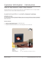
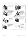
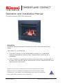
TIMBERFLAME COMPACT
Operation and Installation Manual
(for serial numbers 0901 7042 and above)
Suitability
Domestic heating appliance, suitable for living rooms and open plan
areas.
This heater is not designed:
• To be built directly into a combustible opening, for combustible
opening installations a Rinnai Zero Clearance Box and Flue Kit is
mandatory
• To be installed or operated in places where painting is taking place, or
in places such as hair salons where there is a lot of dust and fluff, and
where aerosols are used
Appliance must only be installed with an approved Rinnai flue system.
Appliance must be installed, commissioned and serviced by a licensed
tradesperson in accordance will all applicable local rules and regulations.
Please retain this manual for future reference.
Rinnai New Zealand
Compact Op/Install Manual: 10170-C 02-09
Limited Warranty
Rinnai brings you peace of mind
with a 2 year minimum warranty.
TERMS AND CONDITIONS
1. During the 24 month period from date of
purchase and subject to clauses 2 and
3 below, Rinnai New Zealand Limited
(“Rinnai”) will, at its own discretion, either
replace or repair any defective product at
no charge to the customer.
3. Warranty claims may be invalid if not
accompanied by details of the installing or
supervising gas fitter’s registration number
and the gas fitting certification number.
4. This warranty commences from the date of
purchase. Proof of purchase is required at
the time of any warranty claim.
2. This warranty covers manufacturing defects
only. This warranty will not apply if (for
example) the product has been improperly
installed or is otherwise installed contrary
to manufacturer’s recommendations, has
been damaged during or after installation,
has not been operated in accordance
with operating instructions, or has been
subjected to damage or abuse beyond that
expected from conditions of normal use.
5. Servicing of the product is to be carried out
by a Rinnai authorised service centre.
All Rinnai appliances meet or exceed the
safety standards required by New Zealand
gas and electrical regulations. The company
is constantly improving its products and as
such specifications are subject to change or
variation without notice.
Please keep these instructions in a safe place for future reference.
RECORD AND ATTACH YOUR PROOF OF PURCHASE BELOW:
Your Retailer:__________________________________________________
Name:________________________________________________________
Address:______________________________________________________
_____________________________________________________________
Telephone:( _______ ) __________________________________________
Date of Purchase: ______ / ______ / _________
Rinnai New Zealand
Compact Op/Install Manual: 10170-C 02-09
Contents
Customer Information
Limited Warranty
2
Introduction
4
Safety
5
General Information
6
Operation
8
Troubleshooting
9
Installation Information
Before Installation
10
Specification
10
Appliance Location
11
Flueing - General Flueing Guidelines
12
Flueing - Masonry Installations and Flexiliner Flue Systems
13
Flueing - Decorative Fireplace Installations and Flueing
14
Installation - Preparation
15
Installation - Gas Connection
16
Installation - Installing the Logset
17
Testing Procedure
18
Commissioning
19
Installer Details
19
Wiring Diagram
20
Customer Contacts
20
WARNING
Improper installation, adjustment, alteration, service or maintenance
can cause property damage, personal injury or loss of life.
For assistance or additional information contact Rinnai on 0800
RINNAI (0800 746 624).
Rinnai New Zealand
Compact Op/Install Manual: 10170-C 02-09
Customer Information - Introduction
Made for New Zealand, made in New Zealand
All Rinnai flame fires are designed and made here in New Zealand to suit our unique climatic
conditions and the needs to New Zealand homeowners.
A great all-round fire in a smartly designed package
Adaptable and safe
The Timberflame Compact has the flexibility to fit into even the tightest of masonry fireplaces.
As with all Rinnai fires, it’s got built-in safety features including an overheat switch and flame
failure detectors.
Perfect features
•
•
•
stylish brushed stainless steel or matt black steel
electronic push-button ignition
2-speed convection fan ensures even heat dispersal over a wide area
Gas Consumption:
Output:
Efficiency:
Heats Area Up To:
Rinnai New Zealand
25 - 9 MJ/h (high to low)
5.0 - 1.6 kW
73%
56 - 78 m2 (depending on the region you live in)
Compact Op/Install Manual: 10170-C 02-09
Customer Information - Safety
Do not restrict warm
air discharge by placing
articles in front of the
appliance.
This appliance
must not be used
for any other
purpose than
heating.
Young children
should be
supervised at all
times. Hand or
body contact with
the appliance must
be avoided.
Do not spray aerosols
while the appliance
is operating. Most
aerosols contain
butane gas, this
can be a fire hazard
if used near the
appliance.
Do not allow anyone to
post articles through
into the heater.
Do not allow
anyone to sit, lean
against or sleep
directly in front of
the appliance
Do not allow curtains
or other combustible
materials to come
into contact with the
appliance
Rinnai New Zealand
Do not unplug
the appliance
while it is
operating. Do
not use power
boards or double
adaptors to
operate this
appliance.
Compact Op/Install Manual: 10170-C 02-09
Customer Information - General
Before operation
Read these instructions to get an overview of how to operate, maintain and service your
Timberflame Compact.
Clearance to combustibles, mantles and surrounds
Combustible clearances
The appliance must not be installed where curtains or other combustible materials could come
into contact with the heater. In some case curtains may need restraining.
Mantles and surrounds
A mantle is allowable providing it is outside the minimum clearances shown.
For an additional overhang, 100 mm of vertical clearance is required for every 50 mm of added
depth. For example, a 100 mm mantle depth requires 400 mm of vertical clearance.
Combustible Clearances
Mantles
300mm
50 mm maximum
at 300 mm above
300mm
300 mm minimum
from top of glass
300mm
1000mm
Floor protection
Heat emanating from this fire may over time affect the appearance of some
materials used for flooring, such as, carpet, vinyl, cork or timber. This may be
amplified if the air contains cooking vapours or cigarette smoke. To avoid this
occurring, it is recommended that a mat be placed in front of the appliance.
Electrical connection
Appliance must not be located below a power socket outlet. If the supply cord is
damaged and requires replacing, it must be replaced by a licensed tradesperson. This
must be a genuine replacement part available from Rinnai.
Rinnai New Zealand
Compact Op/Install Manual: 10170-C 02-09
Customer Information - General
Hearths
A hearth is not necessary but can be used for decorative
purposes or protection of sensitive flooring if required.
Some general guidelines when installing a hearth such as
in an existing masonry fireplace.
•
It must not obscure the front of the fire
•
The bottom of the appliance must be level with the
top of the hearth so there is a continuous level
•
Size should be at least the width and depth of the fire
•
Remember to adjust the dimensions of the cavity to
allow for the hearth
Ensure continuous level
Adjust dimensions of cavity to
allow for the hearth
In some instances an increase in hearth is desired. For the Timberflame range this may affect
aesthetics. The increase in hearth height may cause you to look directly into the vents where
the wiring is visible instead of the flame profile.
Maintenance and servicing
Maintenance
Your heater needs very little maintenance to keep it looking good. All parts of the heater
can be cleaned using a soft, damp cloth and mild detergent. Do not use solvents and do not
attempt to clean the heater while it is hot or operating.
Servicing
Rinnai has a service and spare parts network with personnel who are fully trained and
equipped to give the best advice on your Rinnai appliance. If your appliance needs
servicing, please call Rinnai (0800 746 624) and select option 1 for a service centre in
your area.
For reliable operation Rinnai Flame Fires should be serviced every 2 years (including inspection
of the flue system). If they are in a particularly dusty environment or subject to excess lint,
for example dog hair or where there are newly laid carpets then annual servicing would be
beneficial.
Regular servicing is not covered by the Rinnai warranty.
Do not attempt to carry out any service work other than that mentioned in the troubleshooting
section. If you have any other faults or problems, please refer to your installer or call Rinnai.
Rinnai New Zealand
Compact Op/Install Manual: 10170-C 02-09
Customer Information - Operation
HIGH
LOW
IGN
The words HIGH, LOW and IGN are not part of
the control panel. They have been displayed to
highlight what each of the different settings mean.
Ignition
Firmly press the IGN button for 10 seconds and release. This operates the built-in safety
device and starts the electronic spark (lights to pilot).
If the pilot does not remain alight, wait 2 minutes before retrying ignition. If the heater does
not ignite on initial use it may be due to air remaining in the gas supply line.
Adjusting the heat
Press the buttons from ‘LOW’ to ‘HIGH’. This will ignite additional burners as shown above.
Turning off
Press and release the buttons from ‘HIGH’ to ‘IGN’ until they are in the off position. The fan
will stop when the heater cools.
Fan operation
The fan will operate automatically when the heater warms up and will stop when it cools.
When the heater is on the ‘LOW’ setting the fan may turn off as the heater cools and restart
when warm.
In the event of a power failure
If there is a power failure, turning the heater to the ‘LOW’ setting may allow the heater
to continue operating without overheating. Remaining on the ‘HIGH’ setting will cause the
overheat protection switch to activate. This will shut down the appliance.
Rinnai New Zealand
Compact Op/Install Manual: 10170-C 02-09
Customer Information - Troubleshooting
Symptom
Cause
Solution
Burner will not light
No power present
No gas present
Power cut
Air in gas pipe
Ignition failure
Ensure power cord is plugged in and turned on
Ensure gas supply is turned on
Re-ignite after power is restored
Installer to do - purge air
Repeat ignition steps
Smell of gas
Leaking gas
Turn off gas at meter or LPG cylinder and call installer
Fan not working
Heat switch is not activated
No power present
Allow heater to run on HIGH for approximately 5 mins
Ensure power cord is plugged in and turned on
Small soot deposit
Normal operation
No action required
Severe soot
deposits forming
on logs or glass
Inadequate flue system, incorrect
gas pressure or log misalignment
Call a Rinnai Service Centre
Condensation on
glass
Normal operation
Allow heater to warm-up and condensation will
disappear
Streaky lines on
glass
Normal operation
Clean glass
During installation there will be an initial burning in period where some smoke and smell may
be experienced. This is a normal part of the operation.
The appliance is fitted with an overheat safety switch. Under overheating conditions this switch
will shut off the appliance. If the appliance shuts off repeatedly servicing may be required.
Abnormal flame pattern
Each Rinnai Flame Fire has a distinct flame pattern. This should look the same every time you
start your fire, after an initial warm up period of approximately 20 minutes.
Abnormal flame performance and/or pattern can indicate a problem with your fire, such as
blocked gas injectors or artificial logs/burn media have shifted from when the fire was first
installed. There are some warning signs that could indicate a problem.
•
•
•
Unusual smell from the appliance
Continued difficulty or delay in establishing a flame
Flame appears either very short or very long
Abnormal
Normal
•
•
Flame only burns part way across the burner
Severe soot building up on the inside of the glass door
If any of the above signs occur, please call Rinnai to discuss.
Rinnai New Zealand
Compact Op/Install Manual: 10170-C 02-09
Installation Information - General
Before installation
Unpack the appliance and components and check for damage. DO NOT install any
damaged items.
Check all components have been supplied and that you have the correct gas type.
Read these instructions to get an overview of the steps required before starting the
installation. Failure to follow these instructions could cause a malfunction of the
appliance. This could result in serious injury and property damage.
Specification information
Data Plate
Inside appliance - bottom panel front right hand side
Dimensions
H-645 mm, W-750 mm, D-277 mm
Fan Type
Tangential 2-speed, rating 28 W
Flue - Masonry
Rinnai strongly recommends the use of a Rinnai Flexiliner Flue system. Failure to meet this
criteria may result in an unsafe situation. Installation without a flexiliner flue is permissible
as long as the chimney is checked for soundness and ability to achieve a good draw.
Terminal 43 mm x 245 mm rear discharge (spigot)
Flue - Decorative
Natural draft twin skin flue. Termination, an approved 100 mm cowl must be fitted to
all installations. Decorative chimney installations require a Zero Clearance Box and Zero
Clearance Flue Kit. Flue dimensions, outer - 150 mm, inner - 100 mm.
Gas Connection
½ “ BSP male flare to barrel union
Gas Type
NG or LPG
Noise Level
49 dB(A)
Power Consumption
High 80 W, Standby 4 W
Weight
39 kg
Rinnai New Zealand
10
Compact Op/Install Manual: 10170-C 02-09
Installation Information - Location
Positioning the appliance
Main points governing location are flueing and warm air distribution. The heater must not
be installed where curtains or other combustible materials could come into contact with the
appliance. In some cases curtains may need restraining.
Standard flued appliances draw the air for combustion from the room itself so there is a need
for permanent ventilation (for example, fixed open louvres). This fixed ventilation must be
provided as per NZS:5261.
Enclosure requirements
The heater must be positioned on a flat level surface that allows free movement of the
appliance.
•
Masonry installations, use a slurry of sand and cement to level base as required
•
Decorative installations, the zero clearance box needs to be supported, either construct a
base using board with supporting joists or support with the frame itself
Enclosure Dimensions
Masonry Installation
Decorative Fireplace
W-Width
590 - 740 mm
680 mm
H-Height
640 mm
675 mm
D-Depth
360 mm
370 mm
All dimensions provided are critical to the installation of this
appliance and must be adhered to.
Electrical connection
This appliance has a power cord with a 3-pin plug supplied. The power
cord passes through the slot in the lower left or right hand side of the
heater front assembly.
POWER CORD
RUBBER GROMMET
Rinnai recommends that the heater be plugged into a 230 V 10 Amp
earthed power point. The power point must be a minimum of 300 mm
to the side and must not be above the unit. Alternatively the unit can be
direct wired if the power supply is to be concealed.
The electric isolation switch must be accessible after the appliance has been installed. The
electrical cord is not fire rated and should not come into contact with the fire.
Rinnai New Zealand
11
Compact Op/Install Manual: 10170-C 02-09
Installation Information - Flueing
General flueing guidelines
Every appliance requires a flue system that will draw effectively and safely clear flue products
under all wind and climatic conditions.
It is the responsibility of the installer to ensure that the appliance is provided with an effective
flue. Some guidelines to assist with flue design is listed below. These must be read and
modified as necessary with reference to the particular installation.
Flue Terminal Locations
Must be compliant with ‘Clearances Required for Flue Terminals’ from NZS:5261.2003.
Flue Length
This is required for adequate draw and prevents spill-back of combustion products that can
cause safety sensors to shut down the fire.
•
•
Minimum
Maximum
3.6 m vertical (1.2 m of vertical flue required before any bend or offset)
Rinnai recommend a maximum flue height of 8 m
Flue Systems
For new fireplace installations (installations into a combustible opening) a Rinnai Zero
Clearance Box and Flue Kit is a mandatory requirement to meet warranty conditions.
For masonry installations, to ensure adequate draw, Rinnai strongly recommends the
use of a Rinnai Flexiliner Flue System. Failure to meet this installation criteria may
result in an unsafe situation. Installation without a flexiliner flue is permissible as long
as the chimney has been checked for soundness and ability to achieve a good draw.
Shared Flues
Gas appliances must not be connected to a chimney or flue serving a separate solid fuel
burning appliance.
Flue Cowl Clearance
To ensure the products of combustion are cleared, adequate clearance from the building is
required. The following guideline is recommended.
Flue cowl should have a 500 mm clearance from any part of the building. This also applies to
steeped and pitched roofs which should be 500 mm clear of the ridge line as shown below.
Lesser clearances may provide perfectly adequate flue systems depending on the installation.
500 mm
500 mm
500 mm
500 mm
Rinnai New Zealand
12
Compact Op/Install Manual: 10170-C 02-09
Installation Information - Flueing
Masonry installations and flexiliner flue systems
Check dimensions of opening
Ensure opening is within range provided and if necessary bring them
to the required dimensions. Also check chimney height as inadequate
height can affect product performance. Some installations may require
the chimney height to be extended to reduce down drafts.
Install a Rinnai flexiliner flue system
Ensure a minimum vertical rise of 1.2 m before any change of
direction. Avoid sharp bends as this will restrict the chimney’s ability to
draw.
Installation without a flexiliner is permissible as long as the chimney
has been checked for soundness and ability to achieve a good draw.
Some criteria for checking soundness:
•
All loose/broken bricks must be replaced or repaired ensuring the
chimney is of sound construction and does not leak
•
Chimney must be swept clean and be free from soot and creosote
that may have built up if previously used for a solid fuel fire
•
Any damper plate must be fixed in the open position or removed
•
Any underfloor air supply to the fireplace must be completely
sealed off to prevent secondary air draw
•
An approved chimney cap and cowl must be installed
Rinnai New Zealand
13
640 mm
Check flueway
Ensure there are no obstructions. Provide a firm, flat and sealed base
otherwise noise and vibration may result. Sealed means no holes or
openings in the fireplace.
590 - 740 mm
360 mm minimum depth
100mm Chimney Cowl
100mm Galvanised
Chimney Flashing
300 x 400 mm
100mm Top
Flexi Flue Adaptor
Aluminium
Flexible
Flue
Flexiliner
Flue Adaptor
Compact
Heater
Compact Op/Install Manual: 10170-C 02-09
Installation Information - Flueing
New fireplace installations and flueing
Flat wall
Construct frame
Install zero
clearance box
Install flue
Plaster and
paint
Install heater
For installations into new fireplaces (installation into a combustible opening) a Rinnai Zero
Clearance Box and Zero Clearance Flue Kit is required. Failure to meet this installation criteria
will void any product warranty.
Installing the heater last minimises building debris/dust entering the fire which is common
when building or renovating.
Construct frame and install a zero clearance box BEFORE the dry wall
Refer to instructions supplied with the zero clearance box.
Installation of the zero clearance box needs to be on a level base. If
this is not done the appliance may twist and become damaged and
will void any product warranty.
675 mm
370
mm
680 mm
Install the flue
The flue should be self supporting. This is usually done at the framing stage with flue supports
(x2) provided in the flue kit. These are riveted to the flue. The flue kit components are twinskin and require a 25 mm clearance from combustibles.
Flue
Inner flue
Outer flue
must be ≥ 25 mm from inner flue
Combustible Material
Complete electrical connection
Electrical cord is not fire rated and should not come into contact with the fire. An electrical
isolation switch is also required so positioning of this switch needs to be considered when
assessing where to install the unit.
Rinnai New Zealand
14
Compact Op/Install Manual: 10170-C 02-09
Installation Information - Installation
Plinth Supplied with Heater
2
7
Air Slots
5
10
Air Slots
3
11
6
1
9
4
8
Preparation
1. Position plinth into cavity or zero clearance box. The plinth correctly positions the heater
at the required level and the air slots at either end allow air to pass through and cool the
heater and/or zero clearance box
2. Place the heater on a flat surface and remove the 3 screws holding the fascia (1) in place.
3. Pull the bottom of the fascia forward until clear of the gas control buttons and lift up to
remove from frame.
4. Remove the 2 screws holding the top glass retainer in place and lift off (2).
5. Loosen the 2 screws holding the lower glass retainer in place and remove glass panel (3).
6. Remove the barrel elbow from the gas connection bracket on the base of the heater at the
front right hand side (4). Make sure that the gas flare fitting and gas supply pipe are clean
and free from damage. Fit together ready for fitting to the heater.
7. For installation into a masonry fireplace, the foam strips (5) must be attached to the
heater to provide a seal around the fireplace. If this does not provide an adequate seal an
alternative must be used.
8. Insert the heater into the cavity on top of the plinth, taking care when inserting the gas
supply tube.
9. There are 4 levelling screws at the base of the heater held in place with locknuts. If the
heater does not sit flat when in place it may be necessary to adjust these. The front screws
are accessible with the front of the heater removed. If adjustment of the rear feet is
required, the burner assembly and gas control will need to be removed (6).
10. Once the heater is sitting flat attach it to the wall using the 4 holes (2 per side) on the front
flanges.
Rinnai New Zealand
15
Compact Op/Install Manual: 10170-C 02-09
Installation Information - Installation
Gas connection
Gas pipe sizing must consider the gas input to this appliance as well as other appliances in the
premises. The gas meter and regulator must be specified for the total gas rate. An approved
sizing chart such as the one in NZS:5261 should be used.
Copper supply should be run leaving a flared connection at the position shown. The gas
supply terminates inside the heater and enters the appliance from the rear. As this is a flare
connection, sealant is not recommended.
260
79
43
½" BSP MALE FLARE
Purge supply of air and debris
All foreign materials such as filings must be purged from the gas supply, as they may cause
the gas control valve to malfunction.
Fit heater into place
When the heater is in place and properly secured, attach the gas supply to the supplied barrel
union and tighten.
On completion of work a gas leak test must be carried out. Use a soapy solution on all gas
connections. Leaks will be visible when the soapy solution forms bubbles. When finished, wipe
soapy solution with a rag to remove residue.
Rinnai New Zealand
16
Compact Op/Install Manual: 10170-C 02-09
Installation Information - Installation
Installing the logset
1. Logset preparation
Remove logset and granule packet from packaging. To achieve the correct location of the
logset hold as shown below.
2. Logset positioning into combustion chamber
Tilt the back of the logset upwards locating the front feet (1) behind the unpainted inner
horizontal lip (2). Ensure sides do not touch the combustion chamber walls.
Rotate the back of the logset down using the location of the front feet as pivot points.
3. Logset correctly positioned
Logset will look like picture shown when installed correctly.
1
2
3
4. Adding granules
Gently place granules in front of the main log. Level it with a pencil or screwdriver and remove
excess material. Do not pour granules as dust particles from plastic bag may block the burner
ports. If the logset is to be removed for any reason the granules must be removed first.
Any material that prevents the logs from sitting flat on the burner top can upset the burning
pattern and performance of the heater.
5. Replace glass
Replace the glass ensuring the joint in the glass sealing tape is at the bottom.
Rinnai New Zealand
17
Compact Op/Install Manual: 10170-C 02-09
Installation Information - Testing
Testing procedure
1. Turn gas supply on and plug the unit into the power supply.
2. Refer to data plate for burner pressure and remove front cover panel.
3. Remove test point screw and attach manometer to test point. The test point is on the front
injector block.
4. Light heater, turn to high setting and check pressures.
5. If adjustments are necessary, the regulator is situated on the front of the gas control and
should be set to the pressures on the data plate.
6. After checking pressures, turn the unit off, remove manometer and replace test point
screw.
7. Turn the heater on and off a few times to check ignition.
8. When you are satisfied that the heater is working correctly, reassemble the panels.
All burner aerations are factory preset and cannot be adjusted. If you are unable to get the
unit to operate correctly refer to troubleshooting section of this manual before contacting
Rinnai.
It may take approximately 2 hours of operation for the logs to achieve their full flame pattern
and glow. During the initial burning in period, some smoke and smell may be experienced. The
heater should be run on the high setting in a well ventilated room until these dissipate.
It is the responsibility of the installer to check that under normal conditions of the
appliance, all flue gases are exhausted to the outside atmosphere and that there are no
spillage of combustion gases into the room
Rinnai New Zealand
18
Compact Op/Install Manual: 10170-C 02-09
Installation Information - Commissioning
Complete the installation and commissioning checklist below and make sure this manual is left
with the customer. Explain to the customer about the use and care of the unit and understands
the instructions and operation of the appliance.
If operating without a dress guard please following safety instructions to prevent the risk of
injury.
NO
YES
Appliance positioned in a suitable location? (i.e. clearances, combustibles
etc.)
Was a Rinnai approved flue system installed and is the flue drawing
effectively?
Has specified gas pressures been checked and set?
Is the logset located correctly?
Have the granules been placed evenly and on top of the burner and free of
dust?
Has the appliance been tested for correct operation?
Is the customer fully aware of the operating procedure?
Installer Details
Company name:______________________________________________________________
Installer name:_______________________________________________________________
Address:____________________________________________________________________
___________________________________________________________________________
Phone:_______________________________
Mobile:______________________________
Permit number for installation:___________________________________________________
Signed:______________________________
Rinnai New Zealand
Date:_______________________________
19
Compact Op/Install Manual: 10170-C 02-09
Wiring Diagram
TC
FAN
BL
( +)
(-)
R
OHS
FAN S WITC H
HI/ LOW
(MIC R O)
1 BL
2 R
3 W
W
SV
W
FAN S WITC H
ON/OFF
(T HE R MAL)
+ -
2
1
S PAR KE R
BR
BL
BL
E LE CTR ODE
W
BL
BR
220~240 v
50 Hz
2
1
BL
W
G /Y
1
2
BL
W
IGN S WITC H
(MIC R O)
R
BL
BR
W
G/Y
Red
Blue
Brown
White
Green/Yellow
OHS Overheat Switch
SV
Solenoid Valve
TC
Thermocouple
If the supply cord is damaged or requires replacing, it must be replaced by a licensed
tradesperson. This must be a genuine replacement part available from Rinnai.
Rinnai New Zealand
Consumers:
Installers:
0800 RINNAI (746 624)
0800 TO RINNAI (86 746 624)
Address:
105 Pavilion Drive, Airport Oaks, Mangere, Manukau
PO Box 53177, Auckland Airport, Manukau 2150
Phone:
Fax:
(09) 257 3800
(09) 257 3899
Email:
Websites:
[email protected]
www.rinnai.co.nz and www.rinnai-tradesmart.co.nz
20
Compact Op/Install Manual: 10170-C 02-09