1
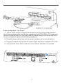
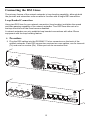
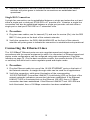
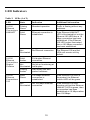
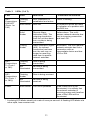
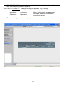
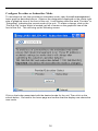
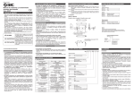
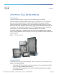
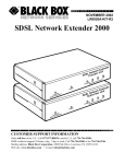
ETHX-DS3-1-LT and ETHX-DS3-2-LT
DS3 EtherXtend Access Device Installation Instructions
Document Number ETH3-A2-ZN10-00
May 2007
Contents
Software and Firmware License Agreement ..................................................... 2
Introduction to ETHX-DS3-1-LT and ETHX-DS3-2-LT...................................... 4
Package Contents ............................................................................................. 5
Release Notes ................................................................................................... 5
Powering Up the Network Extender .................................................................. 6
Connecting the DS3 Lines................................................................................. 8
Connecting the Ethernet Lines .......................................................................... 9
LED Indicators ................................................................................................. 10
Web Interface .................................................................................................. 12
Command Line Interface ................................................................................. 17
Resetting the Network Extender to Factory Defaults ...................................... 19
Specifications .................................................................................................. 22
EMI Notices ..................................................................................................... 23
NEBS Compliance........................................................................................... 23
Service and Repair .......................................................................................... 24
Important Safety Instructions........................................................................... 25
Product Documentation Online ....................................................................... 26
1
Software and Firmware License Agreement
ONCE YOU HAVE READ THIS LICENSE AGREEMENT AND AGREE TO ITS
TERMS, YOU MAY USE THE SOFTWARE AND/OR FIRMWARE INCORPORATED
INTO THE ZHONE PRODUCT. BY USING THE ZHONE PRODUCT YOU SHOW
YOUR ACCEPTANCE OF THE TERMS OF THIS LICENSE AGREEMENT.
IN THE EVENT THAT YOU DO NOT AGREE WITH ANY OF THE TERMS OF THIS
LICENSE AGREEMENT, PROMPTLY RETURN THE UNUSED PRODUCT IN ITS
ORIGINAL PACKAGING AND YOUR SALES RECEIPT OR INVOICE TO THE
LOCATION WHERE YOU OBTAINED THE ZHONE PRODUCT OR THE LOCATION
FROM WHICH IT WAS SHIPPED TO YOU, AS APPLICABLE, AND YOU WILL
RECEIVE A REFUND OR CREDIT FOR THE ZHONE PRODUCT PURCHASED BY
YOU.
The terms and conditions of this License Agreement (the “Agreement”) will apply to the
software and/or firmware (individually or collectively the “Software”) incorporated into
the Zhone product (the “Product”) purchased by you and any derivatives obtained from
the Software, including any copy of either. If you have executed a separate written
agreement covering the Software supplied to you under this purchase, such separate
written agreement shall govern.
Zhone Technologies, Inc (“Zhone”) grants to you, and you (“Licensee”) agree to accept
a personal, non-transferable, non-exclusive, right (without the right to sublicense) to
use the Software, solely as it is intended and solely as incorporated in the Product
purchased from Zhone or its authorized distributor or reseller under the following terms
and conditions:
1. Ownership: The Software is the sole property of Zhone and/or its licensors. The
Licensee acquires no title, right or interest in the Software other than the license
granted under this Agreement.
2. Licensee shall not use the Software in any country other than the country in which
the Product was rightfully purchased except upon prior written notice to Zhone and
an agreement in writing to additional terms.
3. The Licensee shall not reverse engineer, decompile or disassemble the Software
in whole or in part.
4. The Licensee shall not copy the Software except for a single archival copy.
2
5. Except for the Product warranty contained in the manual, the Software is provided
“AS IS” and in its present state and condition and Zhone makes no other warranty
whatsoever with respect to the Product purchased by you. THIS AGREEMENT
EXPRESSLY EXCLUDES ALL OTHER WARRANTIES, WHETHER EXPRESS
OR IMPLIED, OR ORAL OR WRITTEN, INCLUDING WITHOUT LIMITATION:
a.
Any warranty that the Software is error-free, will operate uninterrupted in your
operating environment, or is compatible with any equipment or software
configurations; and
b.
ANY AND ALL IMPLIED WARRANTIES, INCLUDING WITHOUT LIMITATION
IMPLIED WARRANTIES OF MERCHANTABILITY, FITNESS FOR A
PARTICULAR PURPOSE AND NON-INFRINGEMENT.
Some states or other jurisdictions do not allow the exclusion of implied warranties
on limitations on how long an implied warranty lasts, so the above limitations may
not apply to you. This warranty gives you specific legal rights, and you may also
have other rights which vary from one state or jurisdiction to another.
6. IN NO EVENT WILL ZHONE BE LIABLE TO LICENSEE FOR ANY
CONSEQUENTIAL, INCIDENTAL, PUNITIVE OR SPECIAL DAMAGES,
INCLUDING ANY LOST PROFITS OR LOST SAVINGS, LOSS OF BUSINESS
INFORMATION OR BUSINESS INTERRUPTION OR OTHER PECUNIARY LOSS
ARISING OUT OF THE USE OR INABILITY TO USE THE SOFTWARE,
WHETHER BASED ON CONTRACT, TORT, WARRANTY OR OTHER LEGAL
OR EQUITABLE GROUNDS, EVEN IF ZHONE HAS BEEN ADVISED OF THE
POSSIBILITY OF SUCH DAMAGES, OR FOR ANY CLAIM BY ANY THIRD
PARTY.
7. The rights granted under this Agreement may not be assigned, sublicensed or
otherwise transferred by the Licensee to any third party without the prior written
consent of Zhone.
8. This Agreement and the license granted under this Agreement shall be terminated
in the event of breach by the Licensee of any provisions of this Agreement.
9. Upon such termination, the Licensee shall refrain from any further use of the
Software and destroy the original and all copies of the Software in the possession
of Licensee together with all documentation and related materials.
10. This Agreement shall be governed by the laws of the State of California, without
regard to its provisions concerning conflicts of laws.
3
Introduction to ETHX-DS3-1-LT and ETHX-DS3-2-LT
Zhone's ETHX-DS3-1-LT and ETHX-DS3-2-LT are loop bonding Ethernet extenders
that provide up to 45 Mbps (ETHX-DS3-1-LT) or 90Mbps (ETHX-DS3-2-LT) of
symmetrical bandwidth using DS3 lines for transport.
The ETHX-DS3-1-LT features one DS3 port, and the ETHX-DS3-2-LT has two DS3
ports, each capable of up to 45 Mbps bandwidth. One or two ports may be used to
deliver Ethernet connections over DS3 facilities of any given length. Zhone's loop
bonded technology provides automatic load balancing and fail-over for optimum
redundancy and data throughput. In addition the ETHX-DS3-1-LT and ETHX-DS3-2-LT
support industry standard C-Bit Parity DS3 transport facilities, ensuring maximum
distance and flexibility.
The ETHX-DS3-1-LT and ETHX-DS3-2-LT can be connected in any combination so
long as every connection pairs a provider and a subscriber unit.
ETHX-DS3-x-LT units are shipped from the factory configured as provider units. This
configuration can be changed via web management. If you wish to connect a pair of
new units in a point to point network configuration, one of the units must be reconfigured to the subscriber mode. See the “Web Interface” section of this document
for the procedure to accomplish this.
Provider and Subscriber Defaults
The following table highlights the differences between provider and subscriber units.
Table 1. Unit Defaults by Type
Feature
Provider Unit
Subscriber Unit
Default IP Address
192.168.254.252
192.168.254.251
Out of Band Management
Over Ethernet Ports
Over DS3 Ports
Inband Management
Over DS3 Ports
Over Ethernet Ports
Response to Broadcast ARP
Request by IP Address
Unit answers.
Unit does not answer on
DS3 ports; answers only to
ARP request on Ethernet
ports.
4
Package Contents
Unpack and Inspect the network extender. If there is any visible damage, do not
attempt to connect the device. Contact your sales or service provider.
Release Notes
Before installing your network extender, review the release notes for your
model. These are available on the “Service and Support” page under the
documentation heading at the Zhone website.
http://www.zhone.com/support/manuals/net_ext_manuals#rnotes
5
Powering Up the Network Extender
The DC power terminal block on the network extender has five terminals: two positive,
two negative, and one with no connection. Only one positive terminal and one negative
terminal pair need be connected for operational purposes. The second positive and
negative terminal pair may be connected to a backup DC power supply for redundancy.
There is also a system ground terminal on the back panel above the power connector.
Connect this terminal to a reliable source of ground. The ground terminal must always
be connected regardless of the powering connections. DO NOT OPERATE THE
NETWORK EXTENDER WITHOUT A GROUND CONNECTION.
Procedure
Ground Connection
1. Connect a copper wire of at least 18 AWG from a ground source to the ground lug
on the back of the case. In Telco central office installations, the ground source
must be a Common Bonding Network (CB-N)
2 The ampacity of the ground conductor shall be equal to or greater than the
ampacity of the conductor connected to the DC power connection’s DC return.
3 Strip the end of the ground wire. The bare stripped ends of the ground conductor
must be coated with an anti oxidation compound before crimp connections are
made to connector terminals. Crimp a connector, of a suitable size to fit the ground
lug on the chassis, on to the prepared wire end. Use only listed connection
terminals on the ground wire.
4 The ground lug on the unit has two nuts with a star washer between them.
Remove the outer nut and star washer, put the ground connector (prepared in step
3 above) over the ground stud on the chassis. Replace the star washer on the
stud, then the nut. Tighten the nut so that the ground connection is secure and will
not rotate.
Power Connection – DC Power
1. Loosen all screws at the top of the power terminal strip.
2. Insert your –48 VDC lead into the negative (–) terminal of a terminal pair. Tighten
the screw for that terminal.
3. Insert your 48 VDC return lead into the positive (+) terminal of the same terminal
pair as in Step 2. Tighten the screw for that terminal.
4. Repeat Step 2 and Step 3 for the free pair of power terminals if you have a
redundant power supply.
5 Plug the power terminal strip into the power connector on the back of the unit.
6. Verify that the Power LED on the front of the network extender is illuminated.
6
Power Connection – AC Power
1. The AC power supply is shipped with the power terminal strip already attached.
No AC power supply other than the one supplied with the ETHX-DS3-x-LT is approved
for use in powering the unit. Using any other AC power supply could cause the unit to
be non-compliant to emissions and safety regulations.
2 Plug the power terminal strip into the power connector on the back of the unit.
3 Plug the AC power cord into the AC power supply and into a compatible AC outlet.
4. Verify that the Power LED on the front of the network extender is illuminated.
ETHX-DS3-2-LT
7
Connecting the DS3 Lines
The primary feature of the network extender is loop bonding capability, although both
the provider and subscriber units are able to function with a single DS3 connection.
Loop Bonded Connection
Using two DS3 lines for one network connection (loop bonding) multiplies the speed
and data passing capability of the network extender. Two DS3 lines also act as a
backup should one of the lines become disabled.
A network extender can only establish loop bonded connections with other Zhone
equipment with the loop bonding feature.
Procedure
1. Plug the DS3 cables into the DS3 BNC 75 ohm connectors on the back of the
network extender. Each DS3 connection requires two coax cables; one for transmit
(Tx) and one for receive (Rx). Either port can be connected first.
DS3
Tx
Rx
10/100 E
THERNE
T
48VDC
0.45A
1
2
3
4
+ -
NC
- +
DS3
Tx
Rx
Tx
Rx
10/100 E
THERNE
T
48VDC
0.45A
1
2
8
3
4
+ - NC +
2. Verify all connections: the DS3 LINK/ALARM LEDs on the front of the network
extender will pulse green to indicate the connections are established and
operational.
Single DS3 Connection
A single line connection can be established between a single port subscriber unit and
either a single port or dual port ETHX-DS3-x-LT provider unit. Likewise, a single line
connection can also be established between a single port provider unit and either a
single port or dual port ETHX-DS3-x-LT subscriber units.
Procedure
1. Plug two coax cables, one for transmit (Tx) and one for receive (Rx), into the DS3
BNC 75 ohm ports on the back of the network extender.
2. Verify the connection: the DS3 LINK/ALARM LED on the front of the network
extender will pulse green to indicate the connection is established and operational.
Connecting the Ethernet Lines
The 10/100BaseT Ethernet ports can auto-negotiate speed and duplex mode in
accordance with the remote equipment to which it is connected, or Ethernet speed and
duplex mode configurations can be configured using web management. (See Web
Interface on page 12.) For the best connection results, the remote devices (PCs, hubs,
or switches) should be set to auto-negotiate speed and duplex mode.
Procedure
1. Plug the Ethernet cable into one of the 10/100 ETHERNET ports on the back of
the network extender. A straight-through cable can be used for all applications.
2. Verify the connection: solid green illumination of the corresponding
10/100 ETHERNET Connection LINK/ACT (Link/Activity) LED on the front of the
network extender indicates a connection has been established. If the Ethernet
LINK/ACT LED is illuminated but not the Ethernet 100 LED, then a 10 Mbps
connection has been established. If the Ethernet LINK/ACT and 100 LEDs are
both illuminated, then a 100 Mbps connection has been established.
9
LED Indicators
Table 2. LEDs (1 of 2)
LED
State
Indication
Additional Information
10/100
Ethernet
Connections
LINK/ACT
Pulsing
Green
Standard operation
Traffic is flowing without any
problems.
Solid
Green
Ethernet connection is
established
If the Ethernet LINK/ACT
LED is illuminated but not the
Ethernet 100 LED then a 10
Mbps connection has been
established. If the Ethernet
100 LED is also illuminated,
then a 100 Mbps connection
has been established.
Not
Illuminated
No Ethernet connection
The Ethernet 100 and Act
LEDs will remain unlit by
default.
Solid
Amber
Full duplex Ethernet
connection.
Not
Illuminated
No link or functioning at
half duplex.
Pulsing
Amber
Half duplex link with
packet collisions.
Solid
Green
100 Mbps Ethernet
connection is
established
If the Ethernet 100 LED is
illuminated, the Ethernet
Lnk/Act LED will be green.
Not
Illuminated
No 100 Mbps Ethernet
connection
If the Ethernet 100 LED
remains unlit but the Ethernet
LINK/ACT LED is green, then
a connection has been
established at 10 Mbps rather
than 100 Mbps.
10/100
Ethernet
Connections
Duplex/
Collision
10/100
Ethernet
Connections
100
10
Table 2.
LEDs (2 of 2)
Additional Information
LED
State
Indication
DS3
Connections
LINK/ACT
(Ports 1 or
1&2)
Flashing
Green*
DS3 connection is
established and active
Traffic is flowing.
Solid Green
DS3 link
A connection exists but there
is indication of a problem with
the DS3 line.
Solid
Amber
Remote Alarm
Indication (RAI). The
outgoing connection
from the unit has been
lost; no data is being
transmitted.
Yellow alarm. The unit's
partner network extender has
lost its incoming connection
and has LOS.
Pulsing
Amber
Alarm Indication Signal
(AIS). An indirect
connection has been
lost; the unit may no
longer be receiving
data from its partner
network extender.
Blue alarm. The unit's partner
network extender has lost a
connection with an
intermediate device and has
LOS or RAI.
Flashing
Amber
Data is being
transmitted
.
Not
Illuminated
No data is being
transmitted.
Flashing
Amber
Data is being received.
Not
Illuminated
No data is being
received.
Solid Green
The unit is powered
DS3
Connections
Tx (Ports 1
or 1&2)
DS3
Connections
Rx (Ports 1
or 1&2))
Power
If the Power LED is not
illuminated, it is unlikely that
the network extender is
receiving power and therefore
none of the LEDs will be
illuminated
* A pulsing LED blinks steadily at a rate of once per second. A flashing LED blinks at a
more rapid, less constant rate.
11
Web Interface
The network extender’s integral web management lets you configure and monitor the
network extender using a standard web browser.
To manage a Provider unit using web management, connect your PC to any Ethernet
port of the Provider unit.
By default, the Subscriber unit can be managed by the web management through its
Ethernet ports. If you wish to manage the subscriber unit via a DS3 ports, and the unit
still has the default IP address, you must first create a static ARP in your PC.
Establishing an ARP Table Entry for a Subscriber Unit
The subscriber unit’s DS3 ports will not respond to an ARP request containing the
unit’s default IP address. In order to manage the subscriber unit using web
management you must create a static ARP table entry on your PC. To build a static
ARP table entry:
Procedure
Note – This procedure is not necessary if you are connecting directly to the
Ethernet ports on either the provider or subscriber units.
1. Get the MAC address from the bottom label of the subscriber unit.
2. Open a command prompt. (Click on Start, and then Run. In the Open: window
type CMD and press Enter.) At the command line, type:
arp -s 192.168.254.251 xx-xx-xx-xx-xx-xx
where the IP address is the default address of the subscriber unit and the MAC
address is the number on the bottom label. For example: if the MAC address on
the bottom label is 00-50-ca-01-28-86, type:
arp –s 192.168.254.251 00-50-ca-01-28-86
Once the ARP table entry is configured, you can ping and manage the unit using web
management.
If you change the IP address to anything other than the default, the subscriber unit
responds to ARP requests and does not require a static ARP table entry to manage it
using web management.
For security purposes you may want to turn off inband management of the unit to
prevent a local PC from managing the unit from the Ethernet ports.
12
Web Interface System Requirements
Web Browser – Required for running web management. Compatible web
browsers include, but are not limited to, Microsoft Internet Explorer (v4.0 or higher)
and Netscape Navigator (v4.0 or higher). web management is optimized for use
with Internet Explorer.
Use your browser's default settings when running web management. JavaScript
must be enabled.
Screen Resolution – 1024 x 768 pixels is the minimum resolution required for all
web management views to fit within the dimensions of most monitors and laptops.
Lower screen resolutions (such as 800 x 600 pixels) may cause web management
screens to exceed the width or height of the screen. To verify screen resolution on
a Windows system:
—
Right click on your desktop
—
Select Properties
—
Click the Settings tab
—
Adjust the Screen Resolution as needed
Configuring Your Windows PC to Communicate with Web Management
To communicate with web management, your PC’s Ethernet interface must be on the
same subnet as the network extender. For example, to configure the IP address under
Windows XP:
Procedure
1. In the Windows task bar, click on the Start button, and then click on Control Panel.
2. Double-click on the Network Connections icon.
3. In the LAN or High-Speed Internet window, right-click on the icon corresponding to
your network interface card (NIC) and select Properties. (Often this icon is labeled
Local Area Connection.) The Local Area Connection dialog box is displayed with a
list of currently installed network items.
4. Ensure that the check box to the left of the item labeled Internet Protocol (TCP/IP)
is checked, and click on Properties.
5. Write down the current IP Address and Subnet Mask in the Internet Protocol
(TCP/IP) Properties dialog box. When you are done using web management, you
will need to reconfigure your PC with these values.
6. In the Internet Protocol (TCP/IP) Properties dialog box, click in the radio button
labeled “Use the following IP address” and type 192.168.254.x (where x is any
number between 3 and 250, inclusive) in the IP Address field.
7. Type 255.255.255.0 in the Subnet Mask field.
8. Click on OK twice to confirm your changes, and close the Control Panel.
9. Start your web browser. Type 192.168.254.252 (for a provider unit) or
13
192.168.254.251 (for a subscriber unit) into the Address field and press Enter. The
web server opening screen appears.
10. Click on >> Next >>. The login dialog box appears. Log in using:
Username:
superuser
Password:
Password
Note – Username and password
are case sensitive. Enter them
exactly as shown
The web management home page appears.
14
From this screen you can:
Click on . . .
To configure . . .
Management Config.
IP Address, Subnet Mask, Default Gateway,
Inband Management VLAN ID and Priority
Advanced Config.
System Name and Location, Management IP
Address Filter, TFTP and Telnet access
HTTP Password
General and Superuser Passwords
SNMP Config.
SNMP Notification IP Addresses and SNMP
Traps
SNMP Community
SNMP Community Names
Pro/Sub Cfg
Provider or Subscriber mode
IGMP
IGMP configuration, MAC (Display only)
Search (IGMP or MAC)
Srvr Password Time-out Set
Change web management Password Time-out
DSLAM Users
Display only
Show Help
Provides a link to on line help via the Internet
Refresh Screen
Refreshes web management screen
Ethernet Connections Lnk/Act
LEDs
Ethernet Duplex Mode, Speed, and Native
VLAN ID
DS3 Connections Lnk/Alm LEDs
DS3 Circuit Configuration DS3 (Tx Buildout,
and Clock Source, etc), Filter Configuration,
DSCP Rules, IP Rules, MAC Rules, VLAN
Rules, Flood type, Port Statistics, and Port
Copy
15
Configure Provider or Subscriber Mode
To reconfigure a unit from provider to subscriber mode, open the web management
home page as described above. Observe the designation displayed on the center right
side of graphical view of the front of the unit. It will display either the word “Provider” or
“Subscriber” indicating the current mode of the unit. To make a change, click on the
“Pro/Sub Cfg” button which is located just left of center on the graphical view of the
front of the unit. This will bring up the following screen:
Click on the button associated with the desired mode for the unit. Then click on the
submit button. Go back to the home page and confirm that the display now shows the
new mode.
16
Command Line Interface
The network extender can be managed with a Command Line Interface (CLI) through
either a direct PC to COM (Communication) Port connection or from a remote network
connection via Telnet.
CLI System Requirements
Straight-Through 8-Pin Modular Ethernet Cable – Required for establishing a
direct connection from the COM port to a DB9 adapter.
DB9 Female to 8-Pin Modular Male Adapter – Required for conversion of your
PC's RS232 serial port for use with the Ethernet cable.
Terminal Emulation Program – Required for running the CLI over a direct
connection. The program must emulate a VT100 terminal.
Telnet Client – Required for remote management with the CLI. Microsoft Windows
Operating Systems (98, 2000, NT, and XP) include a Telnet client which is run
using the Windows command prompt (cmd.exe). If you are using an operating
system other than Windows, you may need to install a Telnet client.
Connecting a PC Directly
Initial configuration using the CLI requires a direct physical connection from your PC to
the COM port of the network extender you are configuring. (However, the web interface
is recommended for subsequent configuration.)
Procedure
1. Plug a DB9 to 8-pin modular adapter into the RS232 serial port on your PC. See
DB9 to 8-Pin Modular Adapter Pin Assignments on page 21.
2. Connect one end of a straight-through Ethernet cable into the adapter plugged into
your PC, and the other end of the cable into the COM port on the face of the
network extender.
Launching the Terminal Emulation Program
Launch the terminal emulation program on your PC and configure the program
settings. Actual configurations will depend upon the program being used, though
settings should be modeled after the list below; most are standard defaults. Refer to
your terminal emulation program’s user manual for further information.
Baud:
9600
Port:
Com 1
Data Bits:
8
Stop Bits:
1
Flow Control:
none
Transmit Delay:
n/a
Parity:
none
17
Logging Into the CLI
Once your terminal emulation program has been launched, device information is
displayed, followed by a request for username and password. You must log in as a
superuser in order to make configuration changes.
Username:
superuser
Password:
Password
Using the CLI to Establish In band Management
Option 1:
After you have logged in, enter a question mark (?) to list the available commands.
CLI Set commands are used to establish inband management. For example:
set slot 1 ip_address 137.182.10.251
set slot 1 subnet_mask 255.255.255.0
set slot 1 default_gateway 137.182.10.10
The Subscriber unit in this example can now be managed with web management by
attaching a PC to one of the network extender’s Ethernet ports or through the DS3
ports by opening the address 137.182.10.251 in a web browser.
Option 2:
After you have logged in, enter “H” for Help, to list the available commands.
CLI commands are used to establish inband management. For example:
cd syscfg
cd mgtcfg
ipaddress 137.182.10.251
subnetmask 255.255.255.0
defaultgateway 137.182.10.10
submit
Note – It is necessary to type “submit” and hit “enter” for the settings to be enabled
18
Resetting the Network Extender to Factory Defaults
The network extender supports a reset process that may be used to delete the current
configuration and return it to the factory defaults, including the default password.
Procedure
To return the network extender to its factory default configuration:
1. The reset button is located behind a small hole on the left side of the faceplate of
the network extender. Use a straightened paper clip to gently push the button and
let it go.
2. Wait a few seconds until the DS3 Port LEDs flash green starting at Port 1 and
ending at Port 2 (on an ETHX-DS3-2-LT unit). Gently push the reset button again
within 3 seconds of port 1 or port 2 LED illumination. NVRAM is cleared, and all
configurations on the unit are set to the factory defaults.
Note – As mentioned previously, the factory default for mode is “provider”.
Therefore, if the unit was a “subscriber” unit before the reset, the mode must be
changed back to subscriber mode after the reset is complete. The process of
changing the mode is described earlier in this manual.
19
Connector Pin Assignments
Ethernet Pin Assignments
Table 3. Ethernet Pin Assignments
Pin
Function
Pin 1
Rx+
Pin 2
Rx–
Pin 3
Tx+
Pin 4
not used
Pin 5
not used
Pin 6
Tx–
Pin 7
not used
Pin 8
not used
20
DB9 to 8-Pin Modular Adapter Pin Assignments
To connect the COM port to the DB9 serial port of a PC, use an adapter wired as
shown:
Table 4. DB9 to 8-Pin Modular Adapter Pinouts
Pin
8-Pin Modular Port
Direction
PC RS232 Serial Port
Pin
1
Transmit Data
TxD
RxD
Receive Data
2
2
Data Set Ready
DSR
RTS
Request to Send
7
4
Receive Data
RxD
TxD
Transmit Data
3
5
Ground
GN
D
GND
Ground
5
6
Data Terminal Ready
DTR
CTS
Clear to Send
8
Pins not shown are unused.
21
Specifications
Specifications are subject to change without notice.
Table 5. Specifications
Specification
Bandwidth/Distance
Criteria
Up to 44.736 Mbps per DS3 port
ETHX-DS3-1-LT: Up to 44.736 Mbps
ETHX-DS3-2-LT: Up to 89.4 Mbps using loop bonded DS3 circuits
Dimensions
1.25" (3.2 cm) High x 8.5" (21.6 cm) Wide x 4.75" (12.1 cm) Deep
Interfaces
ETHX-DS3-1-LT: 2 BNC 75 ohm jacks (Tx and Rx)
ETHX-DS3-2-LT: 4 BNC 75 ohm jacks (2-Tx and 2-Rx)
4 10/100BaseT 8-position jacks
Operating
Environment
Temperature: 32 F to 122 F (0 C to 50 C)
Non-operating temperature: –40 F to 158 F (–40 C to 70 C)
Humidity: 5% to 95%, non-condensing
Altitude: –200 ft to 16,500 ft (–60 m to 5,000 m)
Power
ETHX-DS3-1-LT: –48 VDC, 0.2 A, 11 W
ETHX-DS3-2-LT: –48 VDC, 0.3 A, 15 W
Protocols Supported
Transparent 802.1D Bridging
DS3 Line Code: C-bit parity (unchannelized DS3)
Regulatory
Compliance
EMC: FCC Part 15; ICES-003; EN 300 386-2; CE Marking
Safety: UL1950, CSA C22.2 No. 950; EN60950; IEC950; CE
Marking
Telecom: FCC Part 68; Industry Canada CS-03
Standards
Supported
IEEE 802.3 Ethernet
IEEE 802.1p Priorities
IEEE 802.1Q VLAN
Weight
1.0 lbs (0.45 kg)
22
EMI Notices
United States – EMI Notice:
This equipment has been tested and found to comply with the limits for a Class A
digital device, pursuant to Part 15 of the FCC rules. These limits are designed to
provide reasonable protection against harmful interference when the equipment is
operated in a commercial environment. This equipment generates, uses, and can
radiate radio frequency energy and, if not installed and used in accordance with the
instruction manual, may cause harmful interference to radio communications.
Operation of this equipment in a residential area is likely to cause harmful interference
in which case the user will be required to correct the interference at his own expense.
The authority to operate this equipment is conditioned by the requirements that no
modifications will be made to the equipment unless the changes or modifications are
expressly approved by Zhone Technologies, Inc.
If the equipment includes a ferrite choke or chokes, they must be installed per the
installation instructions.
Canada – EMI Notice:
This Class A digital apparatus complies with Canadian ICES-003.
Cet appareil num rique de la classe A est conforme la norme NMB-003 du Canada.
NEBS Compliance
The equipment has been tested and found to comply with NEBS requirements as
defined in Telcordia document SR-3580 Issue 2, January 2005 for NEBS Level
1, plus the amendments to this requirement made by Verizon, AT&T and the
Telecommunications Carrier Group in the following documents:
Telecommunications Carrier Group NEBS Checklist
SIT.NEBS.TE.NPI.2004.015, Issued April 4, 2006 (non-Carrier
requirements only)
*
Verizon NEBS Clarification Document SIT.NEBS.RQS.NPI.2004.019,
Issued Feb 27 2006 (non-Carrier requirements only)
*
Verizon NEBS Requirements by Location SIT.NEBS.RQS.NPI.2005.031,
Issued Nov 14 2005 (non-Carrier requirements only)
*
AT&T TP76200, Issue 10, August 11, 2006 (non-Carrier requirements
only)
*
This testing verifies that the equipment meets the requirements for deployment
in a telecommunications carrier’s central office of equipment owned by another
carrier. It does not imply compliance to NEBS for deployment in any other
manner.
23
Service and Repair
If trouble is experienced with this equipment, please contact your local sales
representative, service representative, or distributor directly for any help needed. For
additional information concerning warranty, sales, service, repair, installation,
documentation, training, distributor locations, or Zhone worldwide office locations, use
one of the following methods:
Internet: Visit the Zhone World Wide Web site at www.Zhone.com. (Be sure to
register your warranty at www.Zhone.com/warranty.)
Telephone: Call our automated system to receive current information by fax or to
speak with a company representative.
—
Within the U.S.A. and Canada, call (877) Zhone-20 (946-6320)
—
Outside the U.S.A., call +1 (510) 777-7000
If the equipment is causing harm to the telephone network, the telephone company
may request that you disconnect the equipment until the problem is resolved.
The customer may make no repairs to the equipment.
24
Important Safety Instructions
!
1. Read and follow all warning notices and instructions marked on the product or
included in the manual.
2. Do not allow anything to rest on the power cord and do not locate the product
where persons will walk on the power cord.
3. Do not attempt to service this product yourself, as opening or removing covers
may expose you to hazardous voltage or to other risks. Refer all servicing to
qualified service personnel.
4. General purpose cables are used with this product for connection to the network.
Special cables, which may be required by the regulatory inspection authority for
the installation site, are the responsibility of the customer.
5. When installed, the product must comply with the applicable Safety Standards and
regulatory requirements of the country in which it is installed. If necessary, consult
with the appropriate regulatory agencies and inspection authorities to ensure
compliance.
6. A rare phenomenon can create a voltage potential between the earth grounds of
two or more buildings. If products installed in separate buildings are
interconnected, the voltage potential may cause a hazardous condition. Consult a
qualified electrical consultant to determine whether or not this phenomenon exists
and, if necessary, implement corrective action prior to interconnecting the
products.
7. Input power to this product must be provided by one of the following: (1) a UL
Listed/CSA certified power source with a Class 2 or Limited Power Source (LPS)
output for use in North America, or (2) a certified Class II power source, with a
Safety Extra Low Voltage (SELV) output having a maximum of 240 VA available,
for use in the country of installation.
8. In addition, since the equipment is to be used with telecommunications circuits,
take the following precautions:
—
Never install telephone wiring during a lightning storm.
—
Never install telephone jacks in wet locations unless the jack is specifically
designed for wet locations.
—
Never touch uninsulated telephone wires or terminals unless the telephone
line has been disconnected at the network interface.
—
Use caution when installing or modifying telephone lines.
—
Avoid using a telephone (other than a cordless type) during an electrical
storm. There may be a remote risk of electric shock from lightning.
—
Do not use the telephone to report a gas leak in the vicinity of the leak.
25
Product Documentation Online
Complete documentation for Zhone products is available at www.Zhone.com. Select
Service & Support then select Documentation.
To order a paper copy of a Zhone document, or to speak with a sales representative,
please call (877) Zhone-20 (946-6320).
26
Copyright 2007 Zhone Technologies, Inc.. Printed in U.S.A.
27
* ETH3-A2-ZN10-00*
28