1
NB04D-9150/I
Sears]
owner's
manual
MODEL
NO.
636.795454
I:RRFTSM
37.7 cc
CAUTION:
Read Rules for
Safe Operation
and Instructions
GASBRUSHWACKEWo".
• Assembly
• Maintenance
• Operation
• Repair
Parts
Carefully
Sears,
NB04D.9150/|
6/82
Roebuck
and
Co., Chicago,
Ill. 60684
PRINTED
U.S.A.
IN
JAPAN
°
_......
_'_
:1'"Y'E-,_.R'_WA_ R_A-N
T_'_O
N CR_'A:I=
TS A_N
M _'-'_"
_
_""_
_SHWACKER
_M• 636. 795454
_CKER_M.•
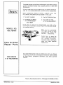
fails to perform properly, due toa defect in material or workmanship with_
in one (1) year from date of purchase Sears will repair it free of charge
c ase, Sears will rep_
,
•
_TM.
is usedfor commercial or rental purposes, this warranty applies for only 90 days from date
_
of purchase.
_
y
_VICE
IS AVAILABLE
8Y SIMPLY CONTACTING
THE NEAREST SEARS STORE OR SERVICE
GHOUT
__c
_t_
-
_'_'; _]_
_",_,_
THE UNITED STATES.
legal rights0 and you may also have other rights which vary from state to state.
Sears, Roebuck & Co•
' ......
Sears Tower
Chicago Illinois 60684
...........
_Z=HXZI._H==Zr==
'_':"
_
' rOv
' _
SAFETY
_ _' _W' _
RULES
_
"_
AND
"_"
_•I
......
'_ _
PRECAUTIONS
X
__
P
1.
Always
wear
properly,
safety
do
not
goggles
wear
for
loose
eye
clothing
could
become caught in moving
footwear
should always be worn,
2.
3.
Inspect the entire
screws, etc.)
DO
NOT
other
the
USE
than
any
use the unit
if it is damaged
the
be cut
Keep the handles
5.
Always
7.
attachment
with
injury
this'
by the
to the
power
user or damage
Do not
use this
Do not overreach•
Do not
proper
Do not smoke while
Always
container
9,
10.
mix
fuel
18.
mix
safety
mixing
in an
and
that
start
store
is approved
the
Never
unit
attempt
the
from
to
is running
make engine
clear surface•
fuel
or run
building.
Fumes
carbon
monoxide•
11.
to cut
or trim
anything
those
for
over
waist
Keep proper
run unit standing
footing
and balance
at all
on a ladder
or any other
Keep hands
and
feet
clear of the
blade while
unit
is in
use.
19•
Do not run the unit at high speed when
20.
Do not use the unit when
you are tired.
handle
and hanging
band
21.
Maintain the unit with
not cutting.
care. Always
fuel or filling
enclosed
22.
the tank.
room
or
fuel
tank
engine
a properly
cap
Do not store ina closed.area where fuel vapors can reach
near
open
Use only replacement parts that are identicalto original
marked
inside
engine
with
the
a closed
contain
adjustments
to the
the unit
operator.
resting
engine
room
your
or attachment
servicingthe unit. These parts are
dealer• The
may
create
use
of
a potential
any
other
hazard,
is
or
dangerous
while
parts when
available from
accessory
while
exhaust
strapped
adjustments
in
the blade
an open flame from hot water heaters,furnaces, etc.
for such usage.
the
make
and
the
keep
sharp. Follow instructionsfor changing accessories.
23.
Never
remove
running.
Never
unit
at a safe
footing•
equipment
8.
away• Onlookers
should be kept
the Work area, at least 30 feet.
high•
cutting.
Do not
flames.
any
cutting•
Do not use this unit for any job other than
which it is intended
as described
in this manual.
of
to the
that
remove
15.
times.
head
may sling during
Also
adjusted•
debris
Keep children
distance from
bolts,
manufacturer
blade•
all
free of oil and fuel.
use the
when
that the unit
in the
%
or poorly
remove
14.
Safe
(Nuts,
entangled
and
t
"
result.
4.
6.
parts.
area to
become
objects
16.
that
unit.
'_ _
Inspect
Dress
jewelry
of the
'_
Do not
17.
for loose
manufactured
Serious
could
or
parts
_,'_"
13.
unstable
those
engine•
engine
machine
protection•
_"_
12.
could
Proper safety precautions must be observed• Like all power
equipment,
this unit must be handled carefully..DO
NOT
EXPOSE YOURSELF
OR OTHERS TO DANGER. Follow
these simple rules:
1
' _
the
Always
on a flat,
CAUTION: The operation ofa,_y BRUSHWACKER_.M.
TrImmer can result in foreign
objects being thrown into the eyes, which
can result in severe eye damage. Always
wear safety glasses or eye shields before
commencing
power tool operation. We recommend Wide
Vision Safety Mask for over spectacles or standard safety
glasses, available at Sears Retail or Catalog Stores•
KNOW
Your
new
BRUSHWACKERT.M.
has been
however,
even with the best of preventative
check out procedures
listed below:
YOUR
carefully
BRUSHWACKERTM
packed
measures,
at the factory
damage
Remove all items from the carton,
lay them out and check
assembly. Also check carefully
for any visible damage.
(IN THE
OR BOTH, NOTIFY
YOUR
SEARS
STORE
IMMEDIATELY.)
You
should
the unit.
familiarize
Refer
yourself
to drawing
with
the various
parts
of
to prevent
does sometimes
your
occur.
damage
the parts to be sure that you
EVENT
THAT SOMETHING
BRUSHWACKERT.M.
during
shipping
It is recommended
before
that
and storage,
you follow
the
have everything
required
for
IS DAMAGED
OR MISSING
attempting
to assemble
or operate
below.
SPECIFICATIONS
MUFFLER:
Lo Tone - w/Cover
37.7 cc (2.30 Cu. In.)
CLUTCH:
Centrifugal
6000
FUEL
IGNITION:
Solid State Ignition
SPARK
PLUG:
CARBURETOR:
Horizontal
Draft,
Float Type
SPARK
PLUG
STARTER:
Auto
ENGINE
TYPE:
2 Cycle
DISPLACEMENT:
OPERATING
ON/OFF
RPM:
SWITCH
Air
Cooled
1 Liter
TANK:
STD
SHOULDER
Pints)
360942
.024" - .028"
Fuel-Oil Mix
Between
20 and 25 to 1
For the first twenty hours,
use the mixing ratio of
Between 15 and 20 to 1
GAP:
LUBRICATION:
Rewind
Togg le (positive "ON/O F F")
(2.1
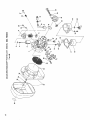
NOTICE:
HARNESS
FUEL TANK
STARTER
DETACHING
HANGING
MET
KNOB
BELT
CHOKE
LEVER
HANDLE
TOGGLE
SWITCH
(POSITIVE
ON/OFF)
AIR CLEANER
DRIVE
SHAFT
BRUSH
HOUSING
_,,_.
HANDLE
BLADE
_._--_-_
/
FIXTURECOMPL
SPLASH
D E F LECTOR
NOTICE
Locate
the
the
number
Model
for
Number
your
records.
of
your
unit.
Record
and
retain
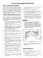
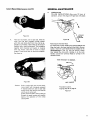
ASSEMBLY
1.
5.
INSTRUCTIONS
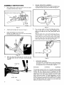
After checking parts, fasten fuel tank and fit drive shaft
to engine with four screws. Figure 1.
GROUND
WIRE
OF TOGGLE
SPLASH DEFLECTOR
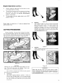
ASSEMBLY
Attach the splash deflector unit to the Drive Shaft Housing using the clamp and screws provided. See figure 4.
SWITCH
/
STAND
Figure 4
Figure 1
You
are now
Lock
on the
6.
.
3.
Attach stand to engine with two bolts. Figure 1.
Clamp
the handle bar to the drive
Connect
the toggle switch cord
from the ignition
coil. Figure 2.
teeth on the
careful!
shaft.
with
the
cord
coming
The arbor
ticular
blade.
from
ready to mount
the blade and
Arbor
end of the drive shaft. CAUTION:
The
blade
shaft
and
are very
nut
sharp.
Wear
gloves
have left hand threads.
attention
to blade rotation
when
Blade has counter-clockwise
rotation
the
blade,
engine
fasten
end of the machine.
the shaft with
lock
When
handle.
and be
Pay par-
installing
the
when viewed
installing
the
Figure 5.
LOCKXANO
Figure 2
4=
@
Wind the spiral tube round both the throttle wire and
the toggle switch cord as in the figure. Attach waist pad.
Figure 3.
Figure 5
7.
WAIST
SHOULDER
PAD
WARNING!
SPIRAL TUBE
Figure
HARNESS
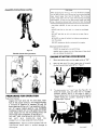
The SHOULDER
HARNESS clips in one of the holes of
the bracket as shown. Adjust so that the blade is parallel
to the ground and you are comfortable. Figure 6.
3
WARNING!
WARNING!
The shoulder harness must be worn, the safety handle installed
properly and both hands kept on the handles at all times while
running this unit. Positive control is mandatory
for safe
operation. DO NOT EDGE WITH THE METAL BLADE! Keep
blades sharp at all times. Splash deflector must be in place
when using brush blades. For blade replacement, use only
blades built for this unit. DO NOT SUBSTITUTE.
Always
shut unit off before disconnecting shoulder harness to examine
blade. BEFORE EACH USE, examine the nuts which hold
blade on to determine if they are tight.
Assembly
Instructions
[€ont'd.|
CAUTION:
When
preparing
for the job
been
stored
stored
fuel
you
mixture,
longer
longer
than
than
performance.
time it should
CAUTION!
mix
only
the amount
needed
are to do. Do not use fuel mixture
two
this
will
(2)
months.
cause
hard
NEVER
fill
the
fuel
tank
Fuel
starting
If fuel mix has been stored
be removed
and filled with
that
has
mixture
and
poor
longer than this
a fresh mixture.
to
the inlet
port
level.
NEVER
add
fuel
to
the
tank
in a closed
un-ventilated
area,
DO
NOT
add
fuel
to
to wipe
off
this
unit
close to an open
fire
or
sparks.
BE SURE
spilled
fuel
before
attempting
to
start the engine.
DO NOT
Check
Figure 6
to refuel
an extremely
hot engine,
points
before operation
CHECK
for loose bolts,
nuts and fittings.
CHECK
the air cleaner
for dirt.
dirt,
Shoulder harness fitting procedure,
attempt
etc. before
ENGINE
Clean the air filter
of all
the operation.
STARTING
PROCEDURE
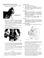
1.
When starting
the engine,
set the toggle switch
at "ON"°
2.
Open the fuel valve. The valve is open when in line with
the fuel line and closed when 90°to it. Figure 7.
I/
OFF
ON
Figure 7
.
PREPARING
FOR
OPERATION
Fuel and oil mixture
Inspect the fuel tank and fill with clean, fresh
fuel of the proper mixture. This engine requires
a mixture of gasoline of between 20 and 25
parts gasoline tolPart oil (1 gal. gasoline to 6 oz.
oil) of regular leaded gasoline. Use 32-36555
Craftsman Engine Oil or a high grade two stroke
cycle engine oil For the first twenty hours, use
the mixing ratio of between 15 and 20 to 1.
DO NOT USE (OUTBOARD
MOTOR)
OIL
DO
NOT
MIX
GASOLINE
AND
OIL
DIRECTLY
IN THE ENGINE FUELTANK.
IMPORTANT:
Failure to follow proper fuel mix
instructions
could result in serious damage to
the engine.
The choke
control
is a "Lever"
choke
engine,
push
the
(CHOKE)
position.
may be started with
"OPEN"
dividual
(RUN)
engine.
OPEN
the
type.
choke
NOTE:
If
the choke
and "CLOSE",
Figure 8.
(See Figure
lever
to
8 ). To
"CLOSE"
the engine
is warm,
it
lever mid-way
between
depending
on
(RUN)
the
in-
.
Figure 8
(con tinued)
Engine
4.
Starting
Procedure
{cont'd}
Stopping
Set the throttle lever at starting position
ing button of throttle lever. Figure 9.
with the lock-
the
Engine
1.
Reduce
the engine
2.
Set the toggle switch
3.
After
stopping
FUEL
rpm to idle.
at "OFF".
the engine,
COCK
...shutting
tank to the engine.
Figure
7.
IMMEDIATELY
off
Figure
CLOSE
the fuel supply
THE
from
the
7.
Adjustments
LOCKING
BUTTON
LEVER
SPARK PLUG MAINTENANCE
-- If the spark plug
electrode area has an excess of carbon buildup, the
efficiency
of the plug will be seriously
reduced.
REMOVE
THE CARBON WITH A SPARK PLUG
CLEANER OR WIRE BRUSH.
OF
After
cleaning
the
spark
plug
RESET
ELECTRODE GAP TO 0.6/0.7 MM (.024-.028).
THE
Carburetor
Figure 9
5.
Pull
the
recoil
Gradually
return
BACK!
Pull
rotation.
DO
starter
the
the
briskly.
in
pull
NOTE:
cord
After
starting
return
the locking
the
of
cord
IT SNAP
the
starter
all the way
one-half
Proper
CAUTION:
LET
direction
the starter
length
10
DO NOT
the
Use only
push
engine,
button
the
pull
choke
the
of throttle
lever
throttle
the
adjustment
operation
carefully
not
of the carburetor
of
this
adjusted
at
require
any further
engine.
the
is very
The
factory
important
carburetor
and
to
has been
therefore
should
adjustmefit.
out
to two-thirds
of
for starting.
After
the engine starts,
"OPEN"
(RUN) position,
6.
Figure
handle...
rope
NOT
of the drum.
your
starter
to
the
lever
and
Carburetor
Adjustment
Idle speed adjustment
throttle
stop screw.
is accomplished
by turning
the
lever.
THROTrLE StOP SCRE,Y
Figure 10
7.
Let
the engine
warm
up by running
it at a low rpm
speed) for approximately
two or three
YOU DO NOT
HAVE
THE
ENGINE
DURING
THE WARM
UP PERIOD.
By moving
(rpm)
unit
to
under
ALWAYS
the
the
throttle
lever,
required
load
reduce
minutes.
UNDER
the engine
rpm
before
speed
placing
the
(cutting).
the
engine
speed
the
the idle
speed. Turning
clockwise
For
any
complete
increase
operating
(slow
NOTE:
LOAD
Turning
to
idle
speed
when
not cutting.
will
throttle
decrease
additional
unit
stop
screw
clockwise
the throttle
stop
will
screw
increase
counter-
the idle speed.
carburetor
to the nearest
adjustments
Sears Service
take
the
Center.
Preventative Maintenance Check List and Storage Tips
Be sure the engine and all other parts are clean.
Check all nuts, bolts, screws, etc. making
tightened and secured as they should be.
sure they are
Inspect carefully for any fuel or oil leaks.
CAUTION_
NEVER
OPERATE
WITHOUT
load,
LOAD.
the engine
adverse
effect
THE
With
ENGINE
throttle
fully
AT
opened
rpm wilt be very high which
on the life
of the engine.
HIGH
RPM
and
no
can have an
Check the air cleaner assembly for excessive dust or dirt.
If the filter
requires cleaning, use the following
procedure: Remove the filter and wash in soap and
water or blow off with compressed air. DO NOT clean
filter in gasoline or other flammable solvent.
Tips for
Long
Drain
Storage
all
spark
fuel from
plug,
the fuel tank
pour a teaspoon
Rotate
the crankshaft
handle
slowly.
of oil through
several
Replace
and carburetor.
times
and the machine
the plug hole.
by pulling
the spark
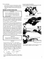
Emergency measure during operation
In case of emergency,
pull the detaching
Remove
will
be detached
from
belt upward
strongly
the body.
the starter
plug and proceed
with
storage.
BRUSH
CUTTER
OPERATION
CAUTION:
Shoulder
harness
kept
the handlebar
on
brush
cutter
datory
action.
cut
operation.
all
blade
rotary
no
mowing
than
flush
in diameter,
or dangerous
areas the unit
or a swing
advancing
will
require
slower
this type cutting
swinging
with the
growth
such
to the
WH
ground,
with
you
to the
are
five
inches
the brush
blade
acquainted
with
you will
want
to control
than to put the full workload
"WRAPPING"
as wire
LITHIUM
large semi-circular
approximately
growth
After
Avoid
Figure 11
effectively
be used similar
applying
forward
action..,
hip rather
and hands.
should
heavier
action.
points
stumpage.
scythe
Cutting
USE
conventional,
2"
to
Lubrication
for its shear cutting
ability
up
each swing.
of
designed
cutting
blade will
with
types
EDGE WITH
The brush cutter
large
action,
arms
is .man-
control
DO NOT
blades.
swings of 6-7 feet
the
Positive
ING
BELT
Caution!
faster
unsightly
For clearing
during
was exclusively
growth,
leaving
hands
grips at all times
BLADE!
It has a much
bar type,
be worn, and both
for safe operation.
METAL
The brush
must
when
grass, Johnsoo
cutting
the
on
JSE SAE30
some
grass, dead,
WEIGHT
OIL
EVERY
30 HOUI
dry,
long stem weeds, grass or vines; there is a possibility
of this
material
"WRAPPING"
around
the blade shaft. This action
can
stall
problem,
the
the
blade
the
unit
machine
material
and cause
should
into
just cut,
the
the clutch
be operated
materials
to
throttle,
be cut
as you make the return
I
to slip. To avoid
at full
and
this
swinging
avoiding
the
swing.
IMPORTANT:
!
_E 30 WEIGHT
Clean and inspect cutter
shaft periodically,
remove debris, etc. to insure optimum
operation.
OIL
EVERY
30 HOURS
I
CAUTION
Stop
engine
Sharpening
kept
the
sharp
keep a file
blade
sharp
the engine
blade
flat
bent
before
surface
blade,
handy;
and
to
blade...the
When
cutting
now and then will
CAUTION:
the blade.
only
Always
lable
shut
the
on a
Always
LITHIUM
keep the
Lay the blade
if it is straight.
to straighten
be
of time
When sharpening
replace
a
and re-use.
GRIND
AS
SHOWN.
blade
blade should
for any length
be sure it is straight.
determine
OR
brush
cutting
precisely.
to sharpen
do not attempt
4-tooth
grass or weed wrappings.
a few strokes
shop
FILE
BLADE
Use the
brush
at all times.
down
in the
worn out,
above.
removing
'_':
for
mowing,
if 4-tooth
grind the base of blade into round
blade
is
curve as shown
at
WHITE
SEARS,
GREASE
ROEBUCK
and SAE
AND
CO.
30 weightOil
Figure
12
are avai
NYL ON LINE
HOW
The
TO USE
Line
work.
Trimmer
depends
cutting.
bricks,
the
for
upon
LINE
is designed
It uses only
specially-treated
THE
wear.
type
trimming
and
light
tip of a monofilament
longer
the
of
The
life
surface
of the
against
edging
nylon
cutting
which
17.
line
line
you
fences.
The
shrubs
and could
cutting
around
line
scar fences.
objects
SAFETY
may
cut
tender
Learning
bark
of
the proper
trees
AND
safety
precautions
mer does not
must
technique
have fast-moving,
sharp metal
blades
but,
1.
safety
do
not
goggles
wear
for
use the unit
when
20.
Maintain
3.
Inspect
the
screws,
etc.)
NEVER
loose
entire
USE
machine
WIRE
IN
MENT
CUTTING
LINE.
cutting
and could
become
4.
Keep the handles
5.
Do not smoke
while
6.
Do
fuel
not
the unit with
of
instructions
the
Do
proper
like all
you
cutting
head
not
cutting.
not store
and
Use only
from
parts
parts
that
when
servicing
dealer.
from
accessory
or attachment
sharp.
fuel vapors
heaters,
your
available
blade
area where
hot water
replacement
keep the cutting
the
line
Follow
accessories.
in a closed
flame
are tired.
care. Always
length
for changing
equipment
Trim-
eye protection.
clothing
could become caught in moving
footwear
should always be worn.
2.
nylon
etc.
are identical
the unit.
The
may
can reach
furnaces,
These parts
use
create
to original
of
any
a potential
are
other
hazard.
ASSEMBLY
wear
properly,
the
Do not
at
rules:
Always
of
19.
power
equipment,
must
be handled
carefully.
DO
NOT
EXPOSE
YOURSELF
OR OTHERS
TO DANGER.
Follow
these simple
clear
at high speed when
an open
Line
feet
run the unit
21.
The
and
is in use.
Do not
PRECAUTIONS
be observed.
unit
18.
22.
Proper
hands
while
or
is very important.
RULES
Keep
are
It will wear faster when you are cutting against rocks,
concrete,
metal fences, etc. than it will against trees or
wooden
INSTRUCTIONS
TRIMMER
for
(very)
TRIMMER
mix
parts
for
jewelry
of the
that
unit.
Safe
loose
parts.
(Nuts,
OF
THE
MONOFILA-
PLACE
The
or
Dress
tip
will
break
a dangerous
To assemble
bolts,
off
your
unit,
follow
the procedures
listed
below:
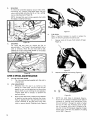
NYLON CUTTING HEAD - LINE TRIMMER
Assemble cup washer, and nylon cutting head as shown
in Figure 13. Align the hole in the lower head with the
hole in the cup washer. Insert the Lock Handle thru the
Holes as shwon, locking the drive shaft. While holding on
to the Lock Handle, screw the nylon cutting head on by
turning in the direction shown.
1.
during
missile.
free of oil and fuel.
mixing
in
fuel or filling
an enclosed
the tank.
room
or
near
open
flames.
7.
Always
mix and store the fuel in a properly
container
that is approved
for such usage.
8.
Never
remove
the
fuel
tank
cap
while
marked
the
engine
is
room
or
running.
9.
Never
start
or run the
building.
Fumes
carbon monoxide.
10.
Never
unit
attempt
11.
12.
Do
not
Inspect
make
and
inside
a closed
exhaust
unit
engine
strapped
adjustments
use the
the
the
contain
dangerous
LOCK
to
is running
make engine
clear surface.
engine
from
adjustments
to the
with
operator.
the unit
if it is damaged
area to
be cut
and
while
Always
resting
on a flat,
o_ poorly
remove
all
HANDLE
the
Figure
NOTE:
adjusted.
debris
For
procedure.
that
opposite
could become entangled in the nylon cutting
head.
Also remove any objects that the unit may sling during
nylon
By
cutting
turning
the
13
head
removal,
nylon
cutting
reverse
head
in
the
the
direction.
cutting.
13.
14.
15.
Keep children
distance
from
away. Onlookers
should be kept
the work area, at least 30 feet.
at a safe
Do not use this unit for any job other than those
which it is intended as described
in this manual.
Do
not
use this
unit
to cut or trim
anything
over
ENGINE
for
To
waist
Do not overreach.
times.
unstable
Do not
footing.
Keep proper
run unit standing
footing
and balance
on a ladder
maximum
the following
Always
2,
Never
engine
and
efticiency,
the engine
to the desired
cutting
line
at
speed
than
cutting.
operate
necessary,
performance
recommendations:
accelerate
speed before
at all
or any other
obtain
observe
1.
high.
16.
OPERATION
the
engine
as this decreases
the
a
Line
higher
Life.
Engine
Operation
Always
3.
release
(cont'd.}
the trigger
and allow
the engine
to return
to idle speed whe'n not cutting.
4
The carburetor
and
not
carburetor
section
5.
has been carefully
should
To
stop
any
adjustment,
in this
position.
require
see
adjusted
further
at the factory
adjustment.
ENGINE
For
ADJUSTMENTS
manual.
engine,
move
Figure
the
toggle
switch
to the
"OFF"
7.
Proper length of cutting
eyelet to end of line.
Figure
MOWING
a.
line is 7 inches as measured from
Your
trimmer
is ideal
lawn
mowers
cannot
mowing
cutting
is shown
line
technique
CUTTING
PROCEDURES
mowing,
is parallel
Always
will
remember,
achieve
the
cutting
right
way
area.
"the
better
Allowing
and wrong
way
tip
results
of the
line does the cutting."
by not
crowding
the unit
to trim
is illustrated
in
the
line
at its own
for mowing
in places conventional
reach.
The
figure
17.
proper
In
to the ground.
will
provide
avoid
pressing
can cause damage
You
in
16
the
results
the head
to your
into
position
for
this
position,
the
With
practice,
this
illustrated.
When
the ground
as this
unit.
into
pace, the
figures14andf&
EDGING
C.
Figure 17
Adjust the drive tube and handle to position the cutting
line as shown in figure 18.
Figure 14
Figure 15
Operating
any
line
could
CAUTION
trimmer
could
eyes.
This
safety
glasses or eye shields
Your
trimmer
the following
A,
lawn
cause
severe
Figure 18
throw
eye
during
is a versatile
objects
damage.
into
Always
the
wear
WARNING!
operation.
tool
which
can easily
perform
care operations:
TRIMMING
The
proper
Maintaining
for
line
trimming
a 30 degree
more efficient
into the work
the cutting.
position
angle to
is shown
the cutting
in
figure
16,
area allows
trimming.
Do not force the cutting
area. Allow
the tip of the line to do
Never lean over the nylon cutting head. Rocks or other
debris could be thrown into eyes and face and cause serious
injury or blindness. ALWAYS WEAR SAFETY GOGGLES
FOR EYEPROTECTION
D°
SCALPING
To remove all unwanted vegetation around trees, posts,
monuments, etc., maintain a 30 degree angle with the
nylon cutting head and allow the tip of the cutting
line to strike the ground. Figure 19.
NOTE: Increased line wear is to be expected when using
the edging or scalping techniques.
Figure 21
C.
Figure
E.
THE
SPOOL
When
it becomes
spool,
the following
1.
Remove
Figure
19
necessary
knob
all
the
For
quick
walk
or
keeping
being
and
easy
clean
up,
7" and "sweep"
driveway.
the
Move
nylon
swept,
the
cutting
as shown
extend
debris
unit
side
head
in figure
the
the cutting
from
parallel
to
line
way
or
replace
the
be used:
from
bottom
of head.
22.
to
from
to
the
a
side,
surface
20.
Figure
2.
Separate
Figure 20
LINE
& SPOOL
NYLON
1.
CUTTING
The
nylon
housing.
Figure
23.
head
supplied
with
this
unit
is
type.
line
a metal
wear
life
on your cutting
technique
and the surface
which you are trimming.
Do not operate at
is necessary
of the
as the
depend
against
than
The
normal
of
speed
blade.
is as
dulling
required
22
from
HEAD
cutting
LINE ADJUSTMENT
1.
Remember
that
a higher
interspool
MAINTENANCE
a manual
B.
rewind
should
SWEEPING
approximately
A,
to
procedure
to
line
perform
will
the
cutting.
Figure 23
2.
When the line wears down,
of head
by turning
Then by gripping
counter
clockwise
notch,
or amount
counter
loosen
knob
clockwise
on bottom
four
lower ring, pull down
at the same time to
desired.
Retighten
knob.
turns.
and turn
the next
Figure21.
3.
NOTE
mounts
two
small
holes on interspool.
Equal aof cord should be indexed at both sides of
interspool
hole
and
and
out
tom
of
row.
Do
by
the
it
nylon
through
cutting
the
other
side.
Following
interspool,
with
nylon
not over fill
cutting
cord
cord is .080".
10
inserting
guiding
interspool.
is 30 feet
Figure 24.
and
cord
center
arrow
in direction
Capacity
diameter
in one
of
slJool
on botof arof nylon
of
cutting
Line & Spool
Maintenance
GENERAL
[€ont'd]
A.
MAINTENANCE
LUBRICATION
FOLLOW INSTRUCTIONS!
After every 10 hours of
operation, remove the plug and fill gear box with grease,
Figure 24
4,
There are two eyelets, one on each side. After the
nylon cord has been threaded through eyelets
with thick side facing shaft holt, (may not be applicable on all heads), insest eyelets in side slots of
housing while inserting interspool. Thus snapping
together both interspool and eyelets in housing
with one motion. Clip ends of nylon to equal
lengths. Thread knob back on shaft and retighten.
See figure 25.
Figure 26
Removing the Trimmer Head
To remove the Trimmer Head( nylon cutting head )do this:
Align the hole in the lower head with the hole in the cup
washer. Insert the Lock Handle which is included in the
BRUSHWACKERT.M. tool kit thru the hole as shown
thus locking the drive shaft. Holding on to the Lock
Handle, unscrew the Universal Head by turning in the
direction shown.
TURN
Figure 25
Caution:
Nylon
cutting
nuous
length,
If
separate
serious
cord must
WAY TO REMOVE.
"
HANDLE
be one conti-
interspool
centered!
pieces are used on each side
injury
THIS
LOCK
with
ASE
may result as you
near the
Provided in tool kit.
Figure31 Key 24 on page 18.
Figure 27
end of use on nylon cord.
Eyelets must be used or the line can cut
through
destroy
cutting
the spool housing and possibly
the operation
of the
nylon
head.
!1
\
t_o
it"
o_
sD
ILl
C_
O
0.
€/)
n,,
<
LU
12
co_
_r
/
.J
z
_
_
_
8
I--
_
....
C
_
__-=a
_-_
S
_J
_J
_3
0
,
..J
r_
w
"IU3
t_
tn
rt-
<
uJ
I-
0
0
o
_
0_0000000
_
ZZZ
2ZZZZZZZZoZ
_
_°_
<
<o
z_=
zz8
_So_S oo
g8 ooo
13
\
\.
\
i
\
o.,
0
-p
IX
I,M
_ZJ
14.
o
0
' '
'
T
o
uJ
0
0
<_:
_
_
.:-__oSozzzzzzoooooo
,
,
, ooo_
oSo
o
0
:E
I--I
_r_
I-
=
e')
t,.,
2
I-:
n_
w
"I-
8_
z
0
l-
nn
€/)
nO
€/)
ill
....
_
_
.a
_
._ ._ c). _
u
<
k_
o
15
\
\
\
\
uf)
r_
/
_D
..I
ILl
Q
0
i
l-.J
<_
Q.
I-:
c_
Q_
Lu
16
/
.!
o
A
0
2
O3
O3
,.=,
"6
t_
fa
m"
_
v
_k
z_
o
o
Uil
i.
-T_q
cx
t-n
.F..--.
r,_
a_
_=
,
-
_
U.l
€,o
>:
I,-
o
E,D
°
_0
IT
q_
u'J
qt
a_
_D
.,J
w
r_
0
i
€_
ml
cr_
o..
€_
hJ
€_
"I"
rl"
€_
€/)
Ill
€/)
18
1%
r,,,
rjD
.J
IJJ
0
X
X"_
_r
,
2
<
t--
0
Q,.
,o
,-
=
E
8
_
_
=
o -_
(O
2
s
(.0
-r
P
u')
p ._
._
.=_
rn
(,0
_
mm_"
rr
0
I.Ll
m_Q<
_-
•
.-o
'''''*'''
ZZZZZZZZZ
0__
ZZZ
ZZZ_
__
O00000_ZZ
_
_9
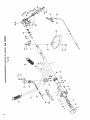
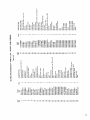
The Model Number will be found on the top of recoil starter. Always
mention the Model Number when requesting service or repair parts
for your unit.
All parts listed herein may be ordered from any SEARS, ROEBUCK
AND CO. OR SIMPSONS-SEARS
LIMITED retail or catalog store.
WHEN
ORDERING
REPAIR
PARTS,
ALWAYS
GIVE
FOLLOWING
INFORMATION
AS SHOWN IN THIS LIST.
1. The PART NUMBER
3. The PART DESCRIPTION
2. The MODEL NUMBER
of the BRUSHWACKERT.M.
636. 795454
4. The NAME OF ITEM37.7cc Gas BRUSHWACKER
T.M.
If the parts
electronically
for expedited
MODEL
THE
you need are not stocked
locally,
your order
transmitted
to a Sears Repair Parts Distribution
handling
will be
center
NO.
When
you
buy
merchandise
from
Sears you
get an extra
something
that
nobody
else
can offer...
Sears Service.
636.795454
Across
town
or
across
the
country,
Sears Service follows
you,
providing
trustworthy,
competent
service technicians
using
factory
How to Order
Repair
Parts
SEARS SERVICE
IS AT YOUR
6/82
Sears
specified
Your Sears Merchandise Takes on added value when you discover
that Sears has Service Units throughout
the country. Each is staffed
by Sears-Trained,
professional
technicians
using Sears. approved
methods.
SERVICE
Sears,
NB04D-9150/3
only
parts.
Roebuck
and
Co.,
Chicago,
Ill. 60684
PRINTEO
U.S.A.
iN
JAPAN