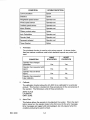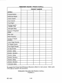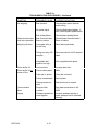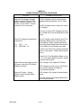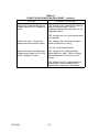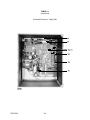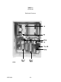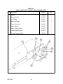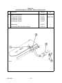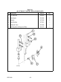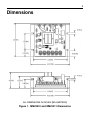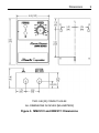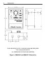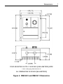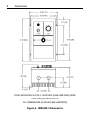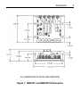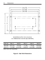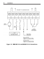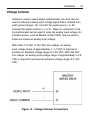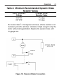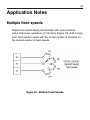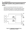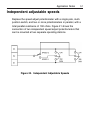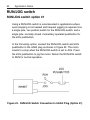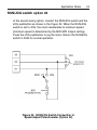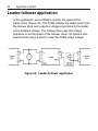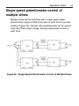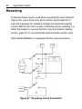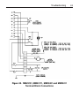
1
OPERATING AND SERVICE MANUAL THERMO ELECTRON AC-4000 CONTROLLER REC 3829 REV M 10/05 PART NO. 045716 REVISION HISTORY REVISION A REVISION B REVISION C REVISION D REVISION E REVISION F REVISION G REVISION H REVISION J REVISION K REVISION L REVISION M OCTOBER 1993 JANUARY 1994 APRIL 1994 FEBRUARY 1995 AUGUST 1995 NOVEMBER 1995 SEPTEMBER 1997 DECEMBER 1997 MAY 1998 FEBRUARY 2000 SEPTEMBER 2000 OCTOBER 2005 COPYRIGHT 1993, 1994, 1995, 1997. 1998, 2000 BY THERMO ELECTRON, INC THIS DOCUMENT IS CONFIDENTIAL AND IS THE PROPERTY OF THERMO. IT MAY NOT BE COPIED OR REPRODUCED IN ANY WAY WITHOUT THE EXPRESS WRITTEN CONSENT OF THERMO. THIS DOCUMENT ALSO IS AN UNPUBLISHED WORK OF THERMO. THERMO INTENDS TO AND IS MAINTAINING THE WORK AS CONFIDENTIAL INFORMATION. THERMO ALSO MAY SEEK TO PROTECT THIS WORK AS AN UNPUBLISHED COPYRIGHT. IN THE EVENT OF EITHER INADVERTENT OR DELIBERATE PUBLICATION, THERMO INTENDS TO ENFORCE ITS RIGHTS TO THIS WORK UNDER THE COPYRIGHT LAWS AS A PUBLISHED WORK. THOSE HAVING ACCESS TO THIS WORK MAY NOT COPY, USE OR DISCLOSE THE INFORMATION IN THIS WORK UNLESS EXPRESSLY AUTHORIZED BY THERMO. PLEASE READ AND OBSERVE THE FOLLOWING SAFETY PRECAUTIONS FOUND THROUGHOUT THIS MANUAL. DANGER FAILURE TO OBSERVE WILL CAUSE VERY SERIOUS PERSONAL INJURY OR DEATH. WARNING FAILURE TO OBSERVE COULD CAUSE SERIOUS PERSONAL INJURY. CAUTION FAILURE TO OBSERVE MAY CAUSE MINOR OR MODERATE PERSONAL INJURY OR DAMAGE TO THE EQUIPMENT. REC 3829 II THERMO RAMSEY ICORE PRODUCTS AC-4000 CONTROLLER TABLE OF CONTENTS CHAPTER 1.0 TITLE INTRODUCTION . . . . . . . . . . . . . . . . . . . . . . . . . . . . . . . . . . . . . . . . . . . . . . . . . 1-1 1.1 1.2 1.3 2.0 PAGE GENERAL DESCRIPTION . . . . . . . . . . . . . . . . . . . . . . . . . . . . . . . . 1-1 1.1.1 Applications . . . . . . . . . . . . . . . . . . . . . . . . . . . . . . . . . . . . 1-1 1.1.2 System Description . . . . . . . . . . . . . . . . . . . . . . . . . . . . . . 1-1 1.1.3 Operation . . . . . . . . . . . . . . . . . . . . . . . . . . . . . . . . . . . . . . 1-1 1.1.4 Features . . . . . . . . . . . . . . . . . . . . . . . . . . . . . . . . . . . . . . 1-3 OPTIONS . . . . . . . . . . . . . . . . . . . . . . . . . . . . . . . . . . . . . . . . . . . . . 1-4 1.2.1 15 Programmable Product Set-Ups . . . . . . . . . . . . . . . . . . 1-4 1.2.2 Statistics (STATS) . . . . . . . . . . . . . . . . . . . . . . . . . . . . . . . 1-4 1.2.3 Multiple Diverter . . . . . . . . . . . . . . . . . . . . . . . . . . . . . . . . . 1-4 1.2.4 Diverter Verification . . . . . . . . . . . . . . . . . . . . . . . . . . . . . . 1-4 1.2.5 Communications (COM) . . . . . . . . . . . . . . . . . . . . . . . . . . 1-4 WARRANTY . . . . . . . . . . . . . . . . . . . . . . . . . . . . . . . . . . . . . . . . . . . 1-7 INSTALLATION . . . . . . . . . . . . . . . . . . . . . . . . . . . . . . . . . . . . . . . . . . . . . . . . . . 2-1 2.1 GENERAL . . . . . . . . . . . . . . . . . . . . . . . . . . . . . . . . . . . . . . . . . . . . . 2-1 2.2 SAFETY PRECAUTIONS . . . . . . . . . . . . . . . . . . . . . . . . . . . . . . . . . 2-1 2.2.1 Occupational Safety and Health Act (OSHA) . . . . . . . . . . . 2-2 2.3 STORAGE . . . . . . . . . . . . . . . . . . . . . . . . . . . . . . . . . . . . . . . . . . . . . 2-2 2.4 UNCRATING & INSPECTION . . . . . . . . . . . . . . . . . . . . . . . . . . . . . . 2-2 2.5 EQUIPMENT LOCATION . . . . . . . . . . . . . . . . . . . . . . . . . . . . . . . . . 2-3 2.6 INSTALLATION . . . . . . . . . . . . . . . . . . . . . . . . . . . . . . . . . . . . . . . . . 2-4 2.6.1 Initial Power On . . . . . . . . . . . . . . . . . . . . . . . . . . . . . . . . . 2-4 3.0 SOFTWARE . . . . . . . . . . . . . . . . . . . . . . . . . . . . . . . . . . . . . . . . . . . . . . . . . . . . 3-1 4.0 MAINTENANCE . . . . . . . . . . . . . . . . . . . . . . . . . . . . . . . . . . . . . . . . . . . . . . . . . . 4-1 REC 3829 4.1 GENERAL . . . . . . . . . . . . . . . . . . . . . . . . . . . . . . . . . . . . . . . . . . . . . 4-1 4.2 SERVICE & REPAIR . . . . . . . . . . . . . . . . . . . . . . . . . . . . . . . . . . . . . 4-1 III TABLE OF CONTENTS (continued) CHAPTER TITLE 4.3 4.4 5.0 COMPONENT REPLACEMENT PROCEDURES (ELECTRICAL) . . . 4-1 4.3.1 Display Board Assembly Replacement . . . . . . . . . . . . . . . 4-1 4.3.2 Display Module Replacement . . . . . . . . . . . . . . . . . . . . . . 4-2 4.3.3 Communication Board Replacement . . . . . . . . . . . . . . . . . 4-2 4.3.4 CPU Board Replacement . . . . . . . . . . . . . . . . . . . . . . . . . . 4-4 4.3.5 Analog Board Replacement . . . . . . . . . . . . . . . . . . . . . . . . 4-4 4.3.6 Distribution Board Replacement . . . . . . . . . . . . . . . . . . . . 4-6 4.3.7 Front Panel Replacement . . . . . . . . . . . . . . . . . . . . . . . . . 4-8 4.3.8 Motor Speed Control Module Replacement . . . . . . . . . . . 4-10 4.3.9 Cold Start Procedure . . . . . . . . . . . . . . . . . . . . . . . . . . . . 4-10 TROUBLESHOOTING . . . . . . . . . . . . . . . . . . . . . . . . . . . . . . . . . . 4-11 REPLACEMENT PARTS . . . . . . . . . . . . . . . . . . . . . . . . . . . . . . . . . . . . . . . . . . . 5-1 5.1 GENERAL . . . . . . . . . . . . . . . . . . . . . . . . . . . . . . . . . . . . . . . . . . . . . 5-1 5.2 ORDER INFORMATION . . . . . . . . . . . . . . . . . . . . . . . . . . . . . . . . . . 5-1 5.3 PARTS LIST INDEX . . . . . . . . . . . . . . . . . . . . . . . . . . . . . . . . . . . . . 5-2 5.3.1 6.0 Return Material Authorization . . . . . . . . . . . . . . . . . . . . . . . 5-3 AC-4000 OPTIONS . . . . . . . . . . . . . . . . . . . . . . . . . . . . . . . . . . . . . . . . . . . . . . . 6-1 6.1 6.2 GENERAL . . . . . . . . . . . . . . . . . . . . . . . . . . . . . . . . . . . . . . . . . . . . . 6-1 6.1.1 Swing Gate Reject System . . . . . . . . . . . . . . . . . . . . . . . . 6-1 6.1.2 Air Bopper Reject System . . . . . . . . . . . . . . . . . . . . . . . . . 6-1 6.1.3 Air Jet Reject System . . . . . . . . . . . . . . . . . . . . . . . . . . . . 6-2 6.1.4 Air Pusher Reject System . . . . . . . . . . . . . . . . . . . . . . . . . 6-2 6.1.5 Carrier Reject System . . . . . . . . . . . . . . . . . . . . . . . . . . . . 6-2 VARIABLE SPEED . . . . . . . . . . . . . . . . . . . . . . . . . . . . . . . . . . . . . . 6-8 6.2.1 6.3 REC 3829 PAGE Installation COMMUNICATIONS . . . . . . . . . . . . . . . . . . . . . . . . . . . . . . . . . . . . 6-8 . . . . . . . . . . . . . . . . . . . . . . . . . . . . . . . . . . . . 6-9 6.3.1 Communication Board Installation . . . . . . . . . . . . . . . . . . . 6-9 6.3.2 External Communication Cabling . . . . . . . . . . . . . . . . . . . 6-11 6.3.3 External Cabling Connections . . . . . . . . . . . . . . . . . . . . . 6-14 6.3.4 Formatted Report . . . . . . . . . . . . . . . . . . . . . . . . . . . . . . 6-14 IV TABLE OF CONTENTS (continued) CHAPTER TITLE 6.3.5 6.4 REC 3829 Installation . . . . . . . . . . . . . . . . . . . . . . . . . . . . . . . . . . . 6-15 Installation . . . . . . . . . . . . . . . . . . . . . . . . . . . . . . . . . . . . 6-16 DIVERTER VERIFICATION OPTION . . . . . . . . . . . . . . . . . . . . . . . 6-16 6.7.1 6.8 . . . . . . . . . . . . . . . . . . . . . . . . . . . . . . . . . . . 6-15 MULTIPLE DIVERTER OPTION . . . . . . . . . . . . . . . . . . . . . . . . . . . 6-16 6.6.1 6.7 Installation MULTIPLE PRODUCT OPTION . . . . . . . . . . . . . . . . . . . . . . . . . . . 6-15 6.5.1 6.6 Free Run Data . . . . . . . . . . . . . . . . . . . . . . . . . . . . . . . . . 6-14 STATISTICS OPTION . . . . . . . . . . . . . . . . . . . . . . . . . . . . . . . . . . . 6-15 6.4.1 6.5 PAGE Installation . . . . . . . . . . . . . . . . . . . . . . . . . . . . . . . . . . . . 6-16 MOTOR INHIBIT OPTION . . . . . . . . . . . . . . . . . . . . . . . . . . . . . . . . 6-17 V LIST OF ILLUSTRATIONS FIGURE NO. TITLE PAGE 1-1 1-2 AC-4000 Electronics . . . . . . . . . . . . . . . . . . . . . . . . . . . . . . . . . . . . . . . . . 1-0 System Block Diagram . . . . . . . . . . . . . . . . . . . . . . . . . . . . . . . . . . . . . . . 1-2 2-1 2-2 2-3 Input Power Connections . . . . . . . . . . . . . . . . . . . . . . . . . . . . . . . . . . . . . 2-4 Analog Board . . . . . . . . . . . . . . . . . . . . . . . . . . . . . . . . . . . . . . . . . . . . . . 2-5 Distribution Board . . . . . . . . . . . . . . . . . . . . . . . . . . . . . . . . . . . . . . . . . . . 2-6 4-1 4-2 4-3 4-4 4-5 Display Board Assembly/Module Replacement . . . . . . . . . . . . . . . . . . . . . Communication, CPU and Analog Board Replacement . . . . . . . . . . . . . . Distribution Board Replacement . . . . . . . . . . . . . . . . . . . . . . . . . . . . . . . . Distribution Board with Options . . . . . . . . . . . . . . . . . . . . . . . . . . . . . . . . . Front Panel Replacement . . . . . . . . . . . . . . . . . . . . . . . . . . . . . . . . . . . . . 6-1 6-2 6-3 Communication Board Switches . . . . . . . . . . . . . . . . . . . . . . . . . . . . . . . . 6-11 EIA-232 Connections . . . . . . . . . . . . . . . . . . . . . . . . . . . . . . . . . . . . . . . . 6-12 EIA-485 Connections . . . . . . . . . . . . . . . . . . . . . . . . . . . . . . . . . . . . . . . . 6-13 4-3 4-5 4-7 4-7 4-9 LIST OF TABLES TABLE NO. TITLE PAGE 1-1 Technical Specifications . . . . . . . . . . . . . . . . . . . . . . . . . . . . . . . . . . . . . . 1-5 4-1 4-2 Troubleshooting Procedures . . . . . . . . . . . . . . . . . . . . . . . . . . . . . . . . . . . 4-12 Power Troubleshooting Procedure . . . . . . . . . . . . . . . . . . . . . . . . . . . . . . 4-17 5-1 AC-4000 Electronics (Remote or Local) . . . . . . . . . . . . . . . . . . . . . . . . . . 5-4 6-1 6-2 6-3 6-4 6-5 6-6 6-7 6-8 Swing Gate Reject System - Replaceable Parts . . . . . . . . . . . . . . . . . . . . Air Bopper Reject System - Replaceable Parts . . . . . . . . . . . . . . . . . . . . . Air Jet Reject System - Replaceable Parts . . . . . . . . . . . . . . . . . . . . . . . . Air Pusher Reject System - Replaceable Parts . . . . . . . . . . . . . . . . . . . . . Variable Speed Option . . . . . . . . . . . . . . . . . . . . . . . . . . . . . . . . . . . . . . . Communication Board Switch Settings . . . . . . . . . . . . . . . . . . . . . . . . . . . Communications Option Parts . . . . . . . . . . . . . . . . . . . . . . . . . . . . . . . . . . External Cabling Connections . . . . . . . . . . . . . . . . . . . . . . . . . . . . . . . . . . REC 3829 VI 6-3 6-5 6-6 6-7 6-8 6-10 6-11 6-14 APPENDIX LIST OF DRAWINGS TITLE A/1 A/3 A/5 A/6 A/7 DRAWING NO. Field Wiring Diagram Full Menu Tree Comm I/Comm II Cable Assembly Comm I/O Cable EIA-232 Comm I/O Cable EIA-485 Engineer Selected D07226K-V002 C07226K-E089 C07190K-E086 D07190K-E087 SUPPLEMENTAL MANUALS TITLE DOCUMENT NO. Minarik Adjustable Speed Control, Model MM 2300 REC 3829 VII MC-3 PREFACE This manual contains information necessary to install, operate, and service the Thermo AC4000 Electronics (see Figure 1-1). All persons concerned with the operation and servicing of the electronics should read the contents of this manual carefully and thoroughly. Keep this manual in a convenient place and refer to it often, as it is an important tool in performing proper service. Information in this manual is presented as follows: Chapter 1.0, INTRODUCTION, presents a brief description of the electronics' capabilities, operation, features, options specifications and warranty. Chapter 2.0, INSTALLATION, outlines site preparation operating requirements, and installation instructions. Chapter 3.0, OPERATION, explains the operating controls and procedures. Chapter 4.0, MAINTENANCE, includes troubleshooting, electronic checkout, and maintenance procedures. Chapter 5.0, REPLACEMENT PARTS, provides ordering information and replaceable parts list. Chapter 6.0, OPTIONS, contains information about optional equipment. The APPENDIX contains assembly, installation, and wiring drawings. IMPORTANT Do not turn the equipment on or attempt to operate the electronics until you have read and understood Chapters 2.0 and 3.0. Improper operation of the electronics may result in damage to the machine. REC 3829 VIII AC-4000 ELECTRONICS FIGURE 1-1 REC 3829 1-0 CHAPTER 1.0 INTRODUCTION 1.1 GENERAL DESCRIPTION The AC-4000 Electronics System is a high accuracy machine. When combined with a weighing frame, it performs weight inspection of individual product packages in a production process or package line. The AC-4000 and a weighing frame perform these functions without interrupting product flow. 1.1.1 Applications Typical applications for the AC-4000 Electronics System are the in-motion weighing of: Frozen food, bakery, confectionery, meat, and any canned or packaged goods. Detergents, chemicals, pharmaceutical, and any bottled liquid products. Manufactured products such as rubber, plastic, metal parts, multi-component parts packages, and count-by-weight packages. 1.1.2 System Description The AC-4000 Electronics System consists of: A microprocessor-based electronic system with filtering and amplification circuitry to interpret the signal from a loadcell. The electronics enclosure houses the CPU, A/D and display boards. A front panel keypad and vacuum fluorescent display. The digital keypad is used to enter set-up parameters. The display presents weight and other statistical data to the operator. Output signals for a reject device or alarm. 1.1.3 Operation Upon installation, certain data must be entered into the AC-4000 electronics. The AC-4000's front panel is designed to simplify set-up and operation of a machine. All data is entered digitally, using the soft keyboard buttons on the front panel. The operator is assisted in set-up by the fluorescent displays that show what data to enter. REC 3829 1-1 SYSTEM BLOCK DIAGRAM FIGURE 1-2 REC 3829 1-2 During operation, the package is transported by a conveying medium (such as chains or belts) across a weightable. The loadcell supporting a weightable produces an electronic signal proportional to the package weight. As the package interrupts a beam from a photocell sensor (interlock), the gross weight of the package is computed by the AC-4000 electronics. This weight is then compared to the setpoint zone settings to determine the appropriate zone. A reject device may then be activated for off-weight packages. The AC-4000 will display the weight class (zone) of the last package weighed, as well as the actual weight of the package in grams, kilograms, ounces or pounds. Using the front panel keyboard, the AC-4000 also will display the total number of packages in each weigh zone and the average weight of the packages in each zone. 1.1.4 Features The AC-4000 Electronics System has the following standard features: 1. Auto Zero and Manual Zero The electronics automatically compensate for minor buildup on the weightable by rezeroing the weightable between packages. Manual zero allows the rezeroing of the weightable at the operator's discretion. 2. Automatic Self-Diagnostics This feature continually monitors system operation and assures that everything is operating properly. A fault relay for connection to an external alarm is provided. 3. Digital Filter Setup During set-up, filter parameters are selected for individual products using the front panel keyboard. This exclusive feature improves the weighing accuracy by providing the best filter setting for each product. 4. Password Protection This feature provides protection against an unauthorized change in set-up parameters and access to certain data. 5. Permanent Data Storage An EEPROM retains set-up information and stores accumulated data. 6. 32-Bit Microprocessor This large memory capacity increases the flexibility of the AC-4000 and allows it to handle a broader range of applications. 7. Corrosion Resistant Finish All exposed metal parts on the AC-4000 Electronics System are either stainless steel or painted mild steel. REC 3829 1-3 1.2 OPTIONS Electronics can be remote or local, and numerous options are available to transform the AC-4000 from a low-cost, basic electronics into a sophisticated tool for monitoring productivity and packaging line performance. These options include the following: 1.2.1 15 Programmable Product Set-Ups The set-up parameters for 15 products can be preset into the electronics. The AC-4000 can then be switched from one product to another in a matter of seconds. 1.2.2 Statistics (STATS) The Statistics option provides statistical information on package weights. 1.2.3 Multiple Diverter The Multiple Diverter option provides for three diverter outputs. The package can be diverted into under-weight, on-weight and over-weight categories if desired. Also can be used for No Gaps (package spacing is too close) or as an alarm actuator to signal remote locations of alarm status. 1.2.4 Diverter Verification The Diverter Verification option provides verification that packages are properly diverted. It generates an alarm if a package which should have been diverted is seen, or if one which should not have been diverted is not seen. 1.2.5 Communications (COM) The Communication option provides for communication of weight or statistical information from the AC-4000 to a printer, CRT, or host computer. The information can be in the form of raw weight data or a formatted report, depending upon the STATS option included with the electronics. Other optional communications capabilities are also available. REC 3829 1-4 TABLE 1-1 TECHNICAL SPECIFICATIONS - AC-4000 ELECTRONICS Line Speed 20 to 350 Ft./Min. (6 to 107 m/min.) Package Rate To 350 PPM Accuracy: Displayed Resolution Electrical Accuracy ±1, ±0.1, or ±0.01 Units ±32 mg for 6000 gram loadcell Zeroing Automatic self zeroing between packages. REZERO light turns on if an autozero cannot occur within two minutes. Weight Zones 3 standard Outputs Machine comes equipped with 110 VAC output signals that may be used to drive rejects or external alarms. Any zone may be set to trigger any of the output signals. Machine includes 32 package reject memory. Environment: Electrostatic Discharge Temperature Humidity Electrical: Standard Neutral to Ground Maximum Voltage REC 3829 5000V 14° to 122° F (-10° to +50° C) 0% to 95% 100-130/200-250 VAC, 50/60 Hz, 300 VA excluding rejecters and alarms 140 Volt AC 1-5 TABLE 1-1 TECHNICAL SPECIFICATIONS - (Continued) REC 3829 1-6 1.3 WARRANTY THERMO ELECTRON WARRANTY The seller agrees, represents, and warrants that the equipment delivered hereunder shall be free from defects in material and workmanship. Such warranty shall not apply to accessories, parts, or material purchased by the seller unless they are manufactured pursuant to seller's design, but shall apply to the workmanship incorporated in the installation of such items in the complete equipment. To the extent purchased parts or accessories are covered by the manufacturer's warranty, seller shall extend such warranty to buyer. Seller's obligation under said warranty is conditioned upon the return of the defective equipment, transportation charges prepaid, to the seller's factory in Minneapolis, Minnesota, and the submission of reasonable proof to seller prior to return of the equipment that the defect is due to a matter embraced within seller's warranty hereunder. Any such defect in material and workmanship shall be presented to seller as soon as such alleged errors or defects are discovered by purchaser and seller is given opportunity to investigate and correct alleged errors or defects and in all cases, buyer must have notified seller thereof within one (1) year after delivery, or one (1) year after installation if the installation was accomplished by the seller. Said warranty shall not apply if the equipment shall not have been operated and maintained in accordance with seller's written instructions applicable to such equipment, or if such equipment shall have been repaired or altered or modified without seller's approval; provided, however, that the foregoing limitation of warranty insofar as it relates to repairs, alterations, or modifications, shall not be applicable to routine preventive and corrective maintenance which normally occur in the operation of the equipment. "EXCEPT FOR THOSE WARRANTIES SPECIFICALLY CONTAINED HEREIN, SELLER DISCLAIMS ANY AND ALL WARRANTIES WITH RESPECT TO THE EQUIPMENT DELIVERED HEREUNDER, INCLUDING THE IMPLIED WARRANTIES OF MERCHANTABILITY AND FITNESS FOR USE. THE SOLE LIABILITY OF SELLER ARISING OUT OF THE WARRANTY CONTAINED HEREIN SHALL BE EXCLUSIVELY LIMITED TO BREACH OF THOSE WARRANTIES. THE SOLE AND EXCLUSIVE REMEDY FOR BREACH OF THE WARRANTIES SET OUT ABOVE SHALL BE LIMITED TO THE REPAIR OR REPLACEMENT OF ANY DEFECTIVE ACCESSORY, PART OR MATERIAL WITH A SIMILAR ITEM FREE FROM DEFECT, AND THE CORRECTION OF ANY DEFECT IN WORKMANSHIP. IN NO EVENT SHALL SELLER BE LIABLE FOR ANY INCIDENTAL OR CONSEQUENTIAL DAMAGES." FIELD SERVICE Purchaser agrees to underwrite the cost of any labor required for replacement; including time, travel, and living expenses of Thermo Ramsey Field Service Engineer at closest factory base. THERMO ELECTRON 501 90th Avenue N.W. Minneapolis, MN 55433 Phone: (763) 783-2500 Fax: (763) 783-2525 REC 3829 1-7 CHAPTER 2.0 INSTALLATION 2.1 GENERAL The customer is responsible for initial inspection of the equipment and site preparation. It is essential that the equipment be placed on the production line in accordance with the guidelines set forth in this section. The customer must ensure that qualified personnel are available to make interconnections with other production equipment and perform work at the installation site. A Thermo Customer Service representative is available to supervise installation and verify operation as well as train personnel assigned to operate and maintain the equipment. 2.2 SAFETY PRECAUTIONS IMPORTANT Do not install, operate, or perform any maintenance procedures until you have read the safety precautions presented below. 1. Do not connect power to the machine or turn on the unit until you have read and understood this entire manual. The precautions and procedures presented in this manual must be followed carefully in order to prevent equipment damage and protect the operator from possible injury. 2. CAUTION! Hands and clothing must be kept away from all moving or rotating parts. 3. WARNING! Covers over the electronics, or rotating parts should always remain in place during operation. They should be removed only for maintenance procedures with the machine's power OFF. Be sure to replace all covers before resuming operation. 4. WARNING! All switches (control, motor, power, etc., as applicable) must be OFF when checking input AC electrical connections, removing or inserting printed circuit boards, or attaching voltmeters to the system. 5. Incoming voltages must be checked with a voltmeter before being connected to the machine. Pay special attention to the red tag attached to the machine that stipulates the correct input voltage for your particular unit. 6. WARNING! Extreme caution must be used in testing in, on, or around the electronics cabinet, PC boards, or modules. There are voltages in excess of 115V, 230V, or 440V in these areas. Avoid high voltage and static electricity around the printed circuit board. 7. CAUTION! Do not leave insulating material over the machine for any length of time or the machine will overheat. The specified maximum ambient temperature is not to be exceeded for more than 5 minutes. 8. Maintenance procedures should be performed only by qualified personnel and in accordance with procedures/instructions given in this manual. 9. During maintenance, a safety tag (not supplied by Thermo) should be displayed in the ON/OFF switch areas as a precaution instructing others not to operate the unit (ANSI:B157.1). 10. Only qualified electricians should be allowed to open and work in the electronics cabinets, power supply cabinets, control cabinets, or switch boxes. REC 3829 2-1 11. Objects of any kind should never be placed or stored on the machine. 12. This equipment should not be operated at more than the specified production rate nor utilized in applications other than those stated in the original order. (To adapt production rates or applications, consult Thermo Products Customer Service for recommendations.) 13. All panels and doors covering the electronics must be in place and tight before conducting wash down. Damage to the electronics could result from water, moisture, or contamination in the electronics housing. 14. Harsh chemicals, caustics, disinfectants, etc., should never be added to wash down solutions. 15. Indeed and outfield conveyors and transfer assemblies should be mounted and/or positioned so clearance is maintained between moving parts. Check to ensure weighing or infeed/outfield conveyor(s) are clear of debris before turning the drive motor ON. 2.2.1 Occupational Safety and Health Act (OSHA) The Occupational Safety and Health Act clearly places the burden of compliance on the user of the equipment and the act is generalized to the extent that determination of compliance is a judgement decision on the part of the local inspection. Hence Thermo Ramsey will not be responsible for meeting the full requirements of OSHA in respect to the equipment supplied or for any penalty assessed for failure to meet the requirements, in respect to the equipment supplied, of the Occupational Safety and Health Act, as interpreted by an authorized inspector. Thermo Ramsey will use their best efforts to remedy such violation at a reasonable cost to the buyer. 2.3 STORAGE If you are not going to install the electronics system now, it can be safely stored at temperatures from -40° F (-40° C) to +158° F (+70° C). All components should be protected against moisture. 2.4 UNCRATING & INSPECTION The electronics system has been properly packaged for shipment. Inspect all packages for damage before opening as often times the carrier may be responsible for shipping damage. 1. Inspect the electronics for shipping damage. 2. Remove the poly covering from the electronics. 3. Cut the nylon shipping bands securing the electronics to pallet. 4. Lift the electronics and pedestal off the pallet. REC 3829 2-2 2.5 EQUIPMENT LOCATION Careful consideration should be given to the location of the electronics, as system performance is affected by its location. The following requirements must be followed. 1. The electronics should be located so maintenance personnel can easily perform cleaning and adjustment procedures, and so both the control panel and electronics enclosure rear doors are easily accessible. This requires clear space behind and in front of the machine. 2. There should be a minimum of vibration in the area. Vibrations can be conducted to a loadcell and affect weighing accuracy. 3. The electronics system is designed to operate in an environment where the temperature ranges no lower than -14° F (-10° C) nor higher than 122° F (50° C). 4. The electronics will operate in an environment where the humidity (non-condensing) ranges from 0% to 95%. REC 3829 2-3 2.6 INSTALLATION The procedures given below provide for installing the electronics in your production line. INPUT POWER CONNECTIONS FIGURE 2-1 2.6.1 Initial Power On The initial power on procedures describe the checks to be performed before the initial system setup procedures are performed. 1. REC 3829 Verify that the fuses on the Analog Board (Figure 2-2) and Distribution Board (Figure 2-3) inside the controller enclosure are correct for the AC input voltage. The following lists define the correct fuses. 2-4 ANALOG BOARD FUSE 115VAC 220VAC F1 (for electronics) 3/8A, 3AG, SB 3/16A, 3AG, SB F2 (for line [L2]) 10A, 3AB, SB 10A, 3AB, SB ANALOG BOARD FIGURE 2-2 REC 3829 2-5 DISTRIBUTION BOARD FUSE 115VAC/220VAC F1 (for Indeed motor) 5A, 3AG, SB F2 (for weightable motor) 5A, 3AG, SB F3 (for outfield motor) 5A, 3AG, SB F4 (for line [L1]) 15A, 3AB, SB F5 (for line [L2]) 15A, 3AB, SB DISTRIBUTION BOARD FIGURE 2-3 REC 3829 2-6 2. Verify that switch SW-2 on the Analog Board is set to the correct AC input voltage. 3. Verify that the dip switches on the Analog Board are correct for your configuration. The following list defines the standard switch settings for the Analog Board, if the specific options noted are installed. (For options see Chapter 6.0.) ANALOG BOARD DIP SWITCHES SWITCH POSITION DESCRIPTION SW1-1 OFF/OPEN* Optional outfield with speed sensor. ON/CLOSED No outfield speed sensor. OFF/OPEN Standard weightable speed sensor. SW1-2 ON/CLOSED* No weightable speed sensor. SW1-3 SW1-8 Others OFF/OPEN* Optional Indeed with speed sensor. ON/CLOSED No Indeed speed sensor. ON/CLOSED* Normal Run position. OFF/OPEN Remove forgotten password. OFF/OPEN Not Used *Standard position. REC 3829 4. Turn the front panel CONVEYOR POWER switch ON and verify that the belt (chains) are running. 5. Turn the ELECTRONICS POWER switch ON and let the electronics warm up. 2-7 This page intentionally left blank This page intentionally left blank This page intentionally left blank This page intentionally left blank REC 3829 4-0 This page intentionally left blank CHAPTER 4.0 MAINTENANCE 4.1 GENERAL Your electronics system is capable of efficient and reliable operation when it is properly maintained. Cleanliness is the most important factor in keeping your electronics in good operating condition. To assist you in servicing your electronics system, information in this section includes: Factory service and repair information. Removal, replacement, and adjustment procedures to assist you in solving repair problems. Troubleshooting procedures. 4.2 SERVICE & REPAIR The maintenance information in this manual is adequate to meet your service needs. However, if you run into problems requiring technical assistance, please call (800)2278891 toll free or (612)783-2700. In addition, Thermo Products Field Service Representatives are fully trained and available from regional offices. Before performing any drastic modifications to this machine, refer to your warranty or contact your Thermo Products Field Service Representative. Thermo Products has a repair center located at our plant in Minneapolis, Minnesota. Please contact our Repair Parts Representative at (612)783-2783 for assistance. Please have available your machine model and serial number as this will expedite your service request. When returning parts for repair, please use the Return Material Authorization form located in the parts section of this manual. 4.3 COMPONENT REPLACEMENT PROCEDURES (ELECTRICAL) CAUTION AVOID HIGH VOLTAGE AND STATIC ELECTRICITY AROUND CIRCUIT BOARDS. 4.3.1 Display Board Assembly Replacement To replace the Display Board, proceed as indicated below. REC 3829 1. Turn off power at mains. 2. Open the electronics controller enclosure door. 3. Disconnect Display Board ribbon cable at J5 (see Figure 4-1). 4. Remove mounting hardware securing Display Board to door of enclosure. 5. Carefully lay Display Board down to gain access to front panel cable. 6. Disconnect front panel cable at Display Board connector J7. 7. Remove Display Board from enclosure. 4-1 8. Place new Display Board in enclosure with Display Board ribbon cable toward the enclosure hinge. 9. Connect front panel cable to Display Board connector J7. 10. Install new Display Board on mounting bolts. 11. Replace mounting hardware securing board to enclosure. 12. Connect Display Board ribbon cable to Display Board connector J7. 13. Close electronics controller enclosure door. 14. Apply power to electronics and verify proper operation. 4.3.2 Display Module Replacement To replace the Display Module, proceed as indicated below. 4.3.3 1. Turn off power at mains. 2. Open the electronics controller enclosure door. 3. Remove the Display Module cable (see Figure 4-1). 4. Remove mounting hardware securing Display Module to enclosure. 5. Remove Module and place the new one on the four threaded studs. 6. Replace the mounting hardware and reconnect the Display Module cable. 7. Close and secure the electronics controller enclosure door. 8. Apply power to electronics and verify proper operation. Communication Board Replacement To replace the Communication Board, proceed as indicated below. REC 3829 1. Turn off power at mains. 2. Open electronics controller enclosure door. 3. Locate the Communication Board (directly above the CPU Board) near the upper, back portion of the enclosure (see Figure 4-2). 4. Gently pull the Communication Board handle, extracting the board from the pin connectors. 5. Place new Communication Board in enclosure. Insure the board is in the upper slot, properly oriented and fully seated. 6. Set all switches on new Communication Board as they were positioned on old board. 7. Verify all setups. Refer to Chapter 3 of this manual for setup procedures. 4-2 DISPLAY BOARD ASSEMBLY/MODULE REPLACEMENT FIGURE 4-1 REC 3829 4-3 4.3.4 CPU Board Replacement To replace the CPU Board, proceed as indicated below. NOTE: If your electronics system is operating erratically, try to capture as much setup data as possible before turning off power. 4.3.5 1. Turn off power at mains. 2. Open electronics controller enclosure door. 3. Locate the CPU Board (directly below the Communication Board) near the upper, back portion of the enclosure (see Figure 4-2). 4. Remove hardware securing CPU board. Gently pull the CPU card handle, extracting the board from the pin connectors. 5. Place new CPU Board in enclosure. Insure the board is in the lower slot, properly oriented and fully seated. 6. Perform a Cold Start Procedure. 7. Verify all setups. Refer to Chapter 3 for all setup procedures. Analog Board Replacement To replace the Analog Board, proceed as indicated below. 1. Turn off power at mains. 2. Open electronic controller enclosure door. 3. Disconnect Analog Board cables J3, J4, J5, J6, J9, J10, J11, J26, and (see Figure 4-2). 4. Unscrew loadcell cables at TB3A and TB3B. Also unscrew all wires on TB4. 5. Remove screw and washer securing Analog Board to enclosure. 6. Remove Analog Board from enclosure. 7. Verify DIP Switch SW1-1 through SW1-8 settings on new Analog Board with old board. 8. Verify fuses. 9. Remove CPU Board and optional Communication Board from old Analog Board and place in the new Analog Board. Verify that the boards are in their proper slots and are fully seated. 10. Place new Analog Board in enclosure. 11. Secure new Analog Board to enclosure. 12. Reconnect loadcell cables to Analog Board, and reconnect wires to TB4. 13. Connect Analog Board cables J3 and J4 to CPU Board connectors J3, J4, J5, J6, J9, J10, J11, J26, and J27. 14. Perform a Cold Start Procedure. 15. Apply power to electronics and recalibrate machine. Refer to Chapter 3 for calibration procedures. REC 3829 4-4 COMMUNICATION, CPU, AND ANALOG BOARD REPLACEMENT FIGURE 4-2 REC 3829 4-5 4.3.6 Distribution Board Replacement To replace the Distribution Board, proceed as indicated below. 1. Turn off power at mains. 2. Open the distribution enclosure box (Figure 4-3). 3. Disconnect main AC power cable at Distribution Board terminal block TB-7. 4. Disconnect drive motor cables at Distribution Board terminal block TB-5. 5. Disconnect diverter cables at Distribution Board terminal block TB-6. 6. Disconnect speed sensor cables at Distribution Board terminal block TB-9. 7. Disconnect wiring to the distribution enclosure at J-14, J-22, J-23, and J-24. 8. Disconnect weightable motor speed control at J-17 and J-18. 9. Disconnect all option cables connected to Distribution Board (Figure 4-4). Refer to the following list. DISTRIBUTION BOARD CONNECTOR OPTION INFEED SPEED CONTROL OUTFEED SPEED CONTROL MOTOR INHIBIT J-15, J16 J-19, J20 TB-8 10. Remove screw securing Distribution Board to enclosure. 11. Remove Distribution Board from enclosure by sliding up and lifting out. 12. Verify that fuses on new Distribution Board are the same as old board. The following list defines the correct fuses. FUSE F1 (Infeed Motor) F2 (Weightable Motor) F3 (Outfeed Motor) F4 (Line [L1]) F5 (Line [L2]) 115/220 VAC 5A 5A 5A 15A 15A TYPE 3AG, SB 3AG, SB 3AG, SB 3AB, SB 3AB, SB 13. Install new Distribution Board in enclosure. 14. Replace screw securing Distribution Board to enclosure. 15. Connect all option cables installed on Distribution Board. 16. Connect weightable motor speed control at J-17 and J-18. 17. Connect wiring to the distribution enclosure at J-14, J-22, J-23, and J-24. 18. Connect speed sensor cables at Distribution Board terminal block TB-9. 19. Connect diverter cables at Distribution Board terminal block TB-5. 20. Connect drive motor cables at Distribution Board terminal block TB-5. 21. Connect main AC power cable at Distribution Board terminal block TB-7. REC 3829 4-6 DISTRIBUTION BOARD REPLACEMENT FIGURE 4-3 DISTRIBUTION BOARD WITH OPTIONS FIGURE 4-4 REC 3829 4-7 22. Close the distribution enclosure box. 23. Apply power to electronics and verify proper operation. 4.3.7 Front Panel Replacement To replace the controller front panel door, proceed as indicated below. Fiberglass Enclosure 1. Turn off power at mains. 2. Disconnect the cables (display board, display module ribbon, and pot/switch) attached to the front door (see Figure 4-5). 3. Using a drive pin, force the hinge pin up from the bottom until it can be grasped with a pliers and removed from the controller enclosure door. 4. Remove the front panel door. 5. Remove the display board and display module from inside the front panel door. 6. Remove the nut(s) securing any externally mounted potentiometers. Also remove switch boot covers securing electronic and conveyor power switches. 7. Remove the pot/switch bracket from the inside of the door (see Figure 4-5). 8. Discard the old front panel door. 9. Fit the controller's new front panel door and insert the hinge pin. 10. Re-install all hardware in reverse order. 11. Reattach cables. 12. Close controller enclosure door. 13. Reapply power to electronics and verify proper operation. Stainless Steel Enclosure 1. Turn off power at mains. 2. Open the controller enclosure door (Figure 4-5). 3. Disconnect display module cable and remove display module. 4. Disconnect display board ribbon and remove display board. 5. Carefully peel front panel off enclosure. If front panel cannot be safely removed, a solvent may be used to help peel the panel off. 6. Peel protective paper off back of new front panel. 7. Mount new front panel on enclosure in same position as old panel. 8. Install display module and connect cable. 9. Install display board and connect ribbon. 10. Close controller enclosure door. 11. Apply power to electronics and verify proper operation. REC 3829 4-8 FRONT PANEL REPLACEMENT FIGURE 4-5 REC 3829 4-9 4.3.8 Motor Speed Control Module Replacement If you find it necessary to replace the motor speed control module, proceed as follows: 1. Turn off power at mains. 2. Open distribution enclosure door (see Figure 4-3). 3. Disconnect cable harness on motor speed control module from Distribution Board connectors J-15 and J-16, or J-17 and J-18, or J-19 and J-20. 4. Remove motor speed control module mounting screws. 5. Remove motor speed control module from enclosure. 6. Remove wiring harness from old speed control module and connect it to the new module. Set all controls (ACCEL, DECEL, MAX. SPEED, MIN. SPEED, TORQUE, and IR COMP) on new module to match old module. (See Minarik MM23000 User's Guide, Chassis Control Connections in the Appendix.) Set 115/230V switches to appropriate settings. WIRE COLOR BOARD CONNECTION (EXTRON OR MINARIK) Brown Yellow Violet Red WIRE COLOR A1 L1 L2 A2 BOARD CONNECTION EXTRON MINARIK Orange Gray Blue 4 2 3 S1 S2 S3 7. Place new motor speed control module in enclosure. 8. Secure new speed control module using screws removed in step 4. 9. Connect cable harness as removed in step 3. 10. Close distribution enclosure door. 11. Apply power to electronics and verify proper operation. 4.3.9 Cold Start Procedure This procedure clears the AC-4000 memory. It is recommeded that this procedure be done each time a printed circuit board is changed or memory is scrambled. Thermo Ramsey also recommends all product and setup information be recorded prior to cold start. Proceed as follows: REC 3829 1. Turn power switch OFF. 2. Turn power switch ON while holding down the CLR key. 3. Front panel display reads: 4-10 Memory Lost Enter All Values 4. 4.4 Procedure complete. Press RUN to re-enter the required setup information which is machine prompted. See Section 3.5, Initial Setup Procedure, for required entries. TROUBLESHOOTING The troubleshooting procedures are listed in a logical sequence in Table 4-1 to enable maintenance personnel to make the fastest checks first. Refer to the listed symptoms and proceed to isolate the possible cause of the failure and apply the recommended corrective action. When the solution recommends replacement of a component or assembly, refer to the Replaceable Parts in Chapter 5.0. Other section references are provided where necessary. If the procedures recommended do not provide a solution to your particular problem, contact Thermo Products Technical Service for assistance. TABLE 4-1 TROUBLESHOOTING PROCEDURES SYMPTOM PROBABLE CAUSE CORRECTIVE ACTION Front panel displays blank; no lamps lit, no keyboard response. Incorrect DC voltage Perform power supply troubleshooting procedures, refer to Table 4-2. Bad Display Replace defective Display Module, refer to Display Module Replacement Procedures in this chapter. Incorrect DC voltage Perform power supply troubleshooting procedures, refer to Table 4-2. Bad Display Board or cable Replace defective Display Module, refer to Display Module Replacement Procedures in this chapter. If problem persists Replace defective Analog Board, refer to Analog Board Replacement Procedures in this chapter. Bad front panel Replace defective front panel, refer to Front Panel Replacement Procedures in this chapter. If problem persists Replace defective Analog Board, refer to Analog Board Replacement Procedures in this chapter. Input from loadcell is zero or less. Check for objects between loadcell and weightable. Front panel display blank or blinking randomly; no display response to lamp test but LED's OK. No response when one or more keys are pressed; i.e., some work and some don't. Message "A/D Under Ranged" REC 3829 4-11 TABLE 4-1 TROUBLESHOOTING PROCEDURES - Continued SYMPTOM PROBABLE CAUSE CORRECTIVE ACTION Message "A/D Over Ranged" Input from loadcell has exceeded A/D input range Check for objects on weightable that exceed loadcell capacity. Message "Outfeed Queue Full" Too many packages on outfeed table Decrease amount of packages between beginning of outfeed and the diverter. Replace or adjust speed sensor. Message "Weightable Queue Full" Multipackage tracking. Too many packages on the weightable Decrease amount of packages between interlock and outfeed deadplates. Replace or adjust speed sensor. Message "Deadplate Queue Full" Excessive deadplate package control Decrease amount of packages between beginning of deadplate and the outfeed. Replace/adjust speed sensor. Incorrect Conveyor Speed Conveyor slows or stops Speed incorrectly set Display speed on front panel and re-adjust speed potentiometer to correct speed. If problem persists Check speed calibration constant and speed sensor. Product build up on drive Clean machine. Timing belt broken or loose Adjust or replace timing belt. Refer to Drive Belt Replacement and Adjustment Procedures in the weightable manual. Seizure of drive shaft bearings Lubricate bearings, or if bearings are defective, refer to Chain Drive Sprocket Replacement Procedures in the weightable manual. Loose drive sprocket or timing gear REC 3829 4-12 Retighten loose set screw on drive sprocket or motor timing gear. TABLE 4-1 TROUBLESHOOTING PROCEDURES - Continued SYMPTOM PROBABLE CAUSE CORRECTIVE ACTION Conveyor slows or stops (continued) Seizure of motor shaft bearings Remove drive motor and rotate shaft. If motor bearings are defective, replace drive motor. Refer to Motor Replacement Procedures in the weightable manual. Infeed, Outfeed or Weightable Conveyor stops Blown drive motor fuse due to motor overload or jam Check drive motor fuses on Distribution Board. If fuse is blown, free conveyor of jam or replace defective drive shaft bearing. Refer to Chain Drive Sprocket Replacement Procedures in the weightable manual. Install new fuses. Blown drive motor fuse due to shorted wiring Using an ohmmeter, measure motor wiring isolation with respect to chassis ground. Locate short and correct wiring. Replace fuses on Distribution Board. Blown drive motor fuse due to motor armature winding Measure motor armature resistance that should be 4 to 6 Ohms, if less than 4 Ohms, replace drive motor. Refer to Drive Motor Replacement Procedures in weightable manual. Replace fuses on Distribution Board. Defective motor speed control module Measure output of motor speed control module. If module output is not between 45 and 90 VDC, replace defective motor speed control module. Refer to Motor Speed Control Module Replacement Procedures in the weightable manual. Fuse 1 = Infeed Fuse 2 = Weightable Fuse 3 = Outfeed REC 3829 4-13 TABLE 4-1 TROUBLESHOOTING PROCEDURES - Continued SYMPTOM PROBABLE CAUSE CORRECTIVE ACTION No Interlocks (Use Interlock Test menu) Dirty interlock Clean interlock. Misaligned interlock or blocked path Realign interlocks or remove blockage using visible red indicator light on receiver as an aid. No power Troubleshoot wiring by checking for +12 VDC between terminals TB4-17 and TB4-18 on Junction Box Board. If voltage is incorrect, per- form Power Troubleshooting checklist per Table 4-2. Interlocks burned out or defective Replace defective interlock. Refer to Interlock system Replacement Procedures in the weightable manual. Bad Analog Board Replace defective Analog Board. Refer to Analog Board Replacement Procedures in this chapter. Blown fuse Check/replace fuse on diverter. No diverter (Use Diverter Test menu) If fuse continues to blow, check/replace solid state relay module on Analog Board. Check/replace faulty diverter mechanism and/or wiring. No diverter while running REC 3829 Optional outfeed speed sensor bad Check outfeed speed display. If zero, check/replace speed sensor and wiring. Analog Board bad Check/replace Analog Board. Refer to Analog Board Replacement Procedures in this chapter. 4-14 TABLE 4-1 TROUBLESHOOTING PROCEDURES - Continued SYMPTOM PROBABLE CAUSE CORRECTIVE ACTION Not weighing Bad Interlock Check/replace photo interlock and/or wiring. No speed signal Check outfeed speed display. If zero, check/replace speed sensor. Bad Analog Board Check/replace Analog Board. Optional communications link inoperative. Bad Communication Board or cables Check/replace Communication Board or cables. Weighing not done Interrogate delay is set too long. Reset interrogate delay. Taking too many A/D samples. Decrease amount of A/D samples taken. Weightable belt speed is too high. Slow weightable belt speed. Printer buffer full Low baud rate. Increase baud rate. Printer buffer full or printer off line Printer needs paper. Refill. Paper jam in printer. Clear jam and reset. Printer is deselected. Select printer. Printing reports too often. Reduce amount of reports. Communication Alarm Receive buffer overflow. Stop data transmission to AC4000. No gap Packages spaced too close together Increase package spacing or check package size for possible skewing. REC 3829 4-15 TABLE 4-2 POWER TROUBLESHOOTING PROCEDURE ACTION Measure DC Voltages at Analog Board Test Points TP2 and TP3, loadcell excitation voltage at TB31,2 and +12V at TB4-2. Use test connector J13-6 as common. CORRECTIVE ACTION If all DC Voltages are OK, perform board troubleshooting procedures, refer to Table 4-1. If all DC Voltages are at or near zero, check AC Voltages. If any one or more of DC Voltages are low or zero, isolate fault to the Analog Board or field wiring. Check AC Voltages at transformer connector J3: J3-1 J3-4 HOT - L1 NEUTRAL - L2 If no AC Voltage, check fuses F4 and F5 on Distribution Board, and F1 and F2 on the Analog Board. Refer to Distribution Board and Analog Board Replacement Procedures in this chapter for fuse location and value. If fuse F4 and F5 are OK, problem exists with main AC input power. Check external power source. If fuse F4 or F5 on Distribution Board or fuse F1 or F2 on Analog Board are blown, replace fuse and restore power. Isolate fault to single board; remove AC power, unplug the CPU Board. Reapply AC power If DC Voltage is OK, replace CPU Board. Remove AC power. Unplug optional Communication Board. Reapply power. If DC voltage is OK, replace Communication Board. If DC Voltage is not OK, plug in CPU Board and check the Display and optional Communication Boards. If not OK, insert Communication Board and check Display Module. REC 3829 4-16 TABLE 4-2 POWER TROUBLESHOOTING PROCEDURE - Continued ACTION Remove AC power and disconnect loadcell cables at TB3. Reapply AC power. CORRECTIVE ACTION If DC Voltage is OK, replace either defective loadcell or loadcell cable. Refer to Weightable Replacement Procedures in the weightable manual. If DC Voltage is not OK, check speed sensor and interlocks. Remove AC power. Disconnect speed sensor and interlock cables. If DC voltage is OK, replace/repair speed sensor and interlock or wiring. If not OK, check Display Module. Remove AC power and disconnect Display Module cable at J6 on CPU Board. Reapply AC power. If DC Voltage is OK, replace defective Display Module or cable. Refer to Display Module Replacement Procedures in this chapter. If DC Voltage is not OK, replace defective Analog Board. Refer to Analog Board Replacement Procedures in this chapter. REC 3829 4-17 CHAPTER 5.0 REPLACEMENT PARTS 5.1 GENERAL This chapter gives information on how to order replacement parts for your AC-4000 Electronics and includes photographs and drawings with corresponding parts lists to enable you to identify parts quickly and accurately. 5.2 ORDER INFORMATION For faster service when ordering parts, fax or telephone Thermo Products Parts Department. Your regional field service representative will also be happy to assist you with parts orders, but his normal scheduling time may delay shipment of your parts order. The recommended procedure for ordering parts is as follows: 1. Determine the broken or faulty part(s). 2. Locate the part(s) in the parts list given. 3. Find the part number(s) for the item(s) needed and determine the quantity you require. 4. Write or telephone: Thermo Electron Customer Service Department 501 90th Ave. NW Minneapolis, Minnesota 55433 Fax: (763) 780-1537 Customers A through G - (763)783-2781 Customers H through O - (763)783-2693 Customers P through Z - (763)783-2782 Repair and Returns - (763)783-2783 Normal Customer Service hours are 8:00 a.m. to 4:30 p.m., Central Time. 5. With your order, list the following information: Machine model and serial number Purchase order number Date required Method of shipment preferred List of parts, including part number, description and quantity Your parts order will handled as expeditiously as possible. REC 3829 5-1 5.3 PARTS LIST INDEX Parts lists are cross referenced to photographs or drawings to facilitate identification. These parts lists are indexed as follows: PARTS LIST DESCRIPTION AC-4000 Electronics (Remote or Local) REC 3829 5-2 TABLE NO. PAGE NO. 5-1 5-4 5.3.1 REC 3829 Return Material Authorization 5-3 TABLE 5-1 AC-4000 ELECTRONICS (Remote or Local) KEY DESCRIPTION PART NO. QTY. Door Assembly, Fiberglass Hinge Pin, Replacement 045765 045836 1 1 2 Potentiometer (Indeed, Weightable, Outfield) 044727 A/R 3 Cable Assembly, Power Switch, Electronics/ Conveyor 045328 A/R 4 Display Board 043259 1 5 Cable Assembly, Analog Board/Display Board 044725 1 6 Cable Assembly, Analog Board/Display Module 044726 1 7 Display Module 042758 1 8 Communication Board 043262 1 9 CPU Board (Select applicable U2 software prom. See Section 6.0) 043253 1 10 Cable Assembly, Signal and Loadcell (for remote AC-4000 and 8000 series frames) 045326 1 11 Cable Assembly, Signal and Loadcell (for remote AC-4000 and 20, 25, 40 and 44 series frames) 045324 1 12 Cable Assembly, COM I/COM II (Optional) 044936 1 1A 1B REC 3829 5-4 TABLE 5-1 AC-4000 ELECTRONICS (Remote or Local) KEY DESCRIPTION PART NO. QTY. 13 Analog Board, 115V Analog Board, 230V 043256 045473 1 A/R 14 Analog Board Fuses: F1, .37 amp, Slo-Blo (for 115V) F1, .19 amp, Slo-Blo (for 230V) F2, 10.00 amp, Slo-Blo 027784 022898 022612 1 A/R 1 15 Motor Control, DC 035269 1 16 Cable Assembly, Controller Enclosure/Distribution Enclosure 044729 1 17 Distribution Board 044687 1 18 Distribution Board with Motor Inhibit 045322 A/R 19 Distribution Board Fuses: F1, F2, F3 - 5 amp, Slo-Blo F4, F5 - 15 amp, Slo-Blo 001369 045320 1 ea 1 ea 20 Cable Assembly, Motor/Rejects (for remote AC4000 and 8000 series frames) 045325 1 21 Cable Assembly, Motor/Rejects (for remote AC4000 and 20, 25, 40 and 44 series frames) 045323 1 22 Cable Assembly, Speed Control/Distribution Board 044718 1 REC 3829 5-5 TABLE 5-1 (Continued) Controller Front Panel REC 3829 5-6 TABLE 5-1 (Continued) Controller Enclosure - Left Side REC 3829 5-7 TABLE 5-1 (Continued) Controller Enclosure - Right Side REC 3829 5-8 TABLE 5-1 (Continued) Distribution Enclosure REC 3829 5-9 CHAPTER 6.0 AC-4000 OPTIONS 6.1 GENERAL Five basic types of reject systems are described in the following pages. These are: Swing Gate Reject System Air Bopper Reject System Air Jet Reject System Air Pusher Reject System Carrier Reject System A brief description of each system and replaceable parts with corresponding referenced drawings are provided for each type of reject system listed above. The reject devices are controlled by the electronics of your checkweigher system and need no other inputs. Product is weighed before reaching the reject position. The timing of the reject is triggered by a photocell interlock system located upstream from the reject mechanism. As product passes the photocell (i.e., as it interrupts the interlock), a reject timing signal is sent from the checkweigher to the reject device, triggering that device to fire (reject) when product reaches the reject position. Information presented below pertains solely to the reject systems listed above. Any other information regarding the electronics or mechanics of your system (including such adjustment procedures as reject timing or photo interlock) can be found in the Operation Chapter. 6.1.1 Swing Gate Reject System The Swing Gate Reject System consists of an air cylinder operated paddle which, when energized, swings across the product path and diverts the product off the side of the conveyor. This paddle should be positioned as close as possible to the conveying medium but should not be in contact with the conveyor. In the rest position, the paddle should be as close as possible to the product path without actually being in the path of the product. This reject system is designed for collapsible product containers or long rigid containers weighing up to 2 lbs. (1 Kg). The maximum allowable line speed is 100 CPM, depending upon product size and weight. The required air pressure also depends upon the product specifications and should be balanced to obtain the desired reject action. The wearable replaceable parts are listed in Table 6-1. 6.1.2 Air Bopper Reject System The Air Bopper Reject System consists of a polyurethane bopper plate operated by a double-acting air cylinder and a 4-way solenoid valve which provide air pressure for both the extending and retracting actions of the bopper plate. When energized, the bopper plate travels across the product path and "bops" the product off the side of the conveyor. This reject system is designed for the high speed reject (up to 350 CPM) of smaller products (cans, bottles, and rigid boxes) weighing up to 1.5 lbs. (0.68 Kg). REC 3829 6-1 The Air Bopper Reject should be mounted perpendicular to the conveying medium and as close as possible (without touching) to the product and the conveying medium. The air pressure required depends on product specifications and should be balanced to obtain the desired reject action. The wearable replaceable parts are listed in Table 6-2. 6.1.3 Air Jet Reject System The Air Jet Reject System consists of two (2) OSHA approved air nozzles mounted on an air manifold and controlled by a solenoid valve. When energized, jets of air blow the product off the conveying medium. To avoid possible contamination of the air supply, the system's air filter and regulator assembly does not contain a lubricator. The air pressure required depends on product weight and should be adjusted to obtain the desired reject action. This reject system is designed for rigid product containers weighing up to 2.5 lbs. (1.1 Kg) for chain conveyor applications and up to 1 lb. (0.5 Kg) for mylar belt conveyor applications. The maximum allowable line speed for this reject system is 400 CPM, depending upon product size and weight. The wearable replaceable parts are listed in Table 6-3. 6.1.4 Air Pusher Reject System The Air Pusher Reject System consists of a stainless steel rectangular plate or an anodized aluminum round plate operated by a double acting air cylinder and a 4way solenoid valve which provide air pressure for both the extending and the retracting actions, of the reject plate. When energized, the Air Pusher plate travels across the product path and pushes the product off the side of the conveyor. This reject system is designed for heavier products, 5 to 40 lbs. (2.3 to 28 Kg), and slower line speeds (40 to 80 CPM). The round reject plate is used for rigid product containers. The rectangular reject plate is used for collapsible product containers. The Air Pusher Reject should be positioned as close as possible to (without touching) the product. It should be mounted as close as possible to the conveying medium to prevent tipping the product when rejected. This height is generally about the mid-section of the product container. The air pressure required depends upon product specifications and should be balanced to obtain the desired reject action. The wearable replaceable parts are presented in Table 6-4. 6.1.5 Carrier Reject System The Carrier Reject System represents the most gentle handling mechanism know for rejection applications. A series of channels (from one to five) is built into the carrier reject and signals from the checkweigher cause the carrier plaques to divert product to the desired channel. This reject system operates at any speed and handles products of any size and weight compatible with the electronics. REC 3829 6-2 TABLE 6-1 SWING GATE REJECT SYSTEM - REPLACEABLE PARTS Key Description Part No. Qty. 1 Paddle 032082 1 2 Gusset, Paddle 034407 2 3 Air Cylinder 025231 1 4 Bushing, Flange 027907 4 5 Pivot, Swing Gate 032549 1 6 Pivot, Cylinder 033123 1 7 Shaft, Cylinder Mount 031874 1 8 4-Way Solenoid Valve 014877 1 9 Tru-Arc Retaining Ring 027868 3 REC 3829 6-3 TABLE 6-1 (Continued) SWING GATE REJECT SYSTEM - REPLACEABLE PARTS Key Description Part No. Qty. 10 Air Filter Regulator, 1/4 NPT w/Gauge 026178 1 REC 3829 6-4 TABLE 6-2 AIR BOPPER REJECT SYSTEM - REPLACEABLE PARTS Key Description Part No. Qty. 1 Bopper Plate Molding 026505 1 2 3" Stroke Air Cylinder 4" Stroke Air Cylinder 6" Stroke Air Cylinder 8" Stroke Air Cylinder 034407 014325 014326 014327 Select One 3 4-Way Valve 014877 1 4 Air Regulator/Filter Assembly w/Gauge 026178 1 REC 3829 6-5 TABLE 6-3 AIR JET REJECT SYSTEM - REPLACEABLE PARTS Key Description Part No. Qty. 1 *Air Manifold 026936 1 2 Hex Nipple 021060 2 3 Nozzle 027659 2 4 Hex Bushing 027991 1 5 Solenoid Valve 051294 1 6 Air Regulator w/Gauge and Filter 041137 1 REC 3829 6-6 TABLE 6-4 AIR PUSHER REJECT SYSTEM - REPLACEABLE PARTS Key Description Part No. Qty. 1 Bopper, Plate 7.0" Lg. 021506 1 2 4" Stroke Air Cylinder 6" Stroke Air Cylinder 8" Stroke Air Cylinder 014325 014326 014327 Select One 3 4-Way Valve 014877 1 4 Air Regulator/Filter Assembly w/Gauge 026178 1 REC 3829 6-7 6.2 VARIABLE SPEED Variable speed option is provided for those applications requiring variable conveyor line speeds. With the variable speed option, you can adjust the speed of your weightable and Indeed or outfield conveyors right at the front panel. The controls are screw driver adjustable and remain wash down sealed when not in use. 6.2.1 Installation To install the variable speed option proceed as follows: 1. Turn off power at mains. 2. Open the controller enclosure door. 3. Remove the switch/pot bracket from the door. 4. With a knife, cut through the hole(s) in the front panel. 5. Install the spacer onto the potentiometer(s) and tighten. 6. Insert the potentiometer(s) spacer through the front panel. 7. From the front of the panel, insert the O-ring on the spacer threads. 8. Install the jack cover and jack cover nut on the protruding spacer threads and tighten. TABLE 6-5 VARIABLE SPEED OPTION PARTS Description Part No. Qty. Potentiometer (Indeed, Weightable, Outfield) 044727 A/R Power Switch (Electronics and Conveyor) 045328 A/R Boot, Switch, Toggle 026856 A/R Jack Cover, Sealed 034966 A/R O-Ring, .375" x .50" x .062" 023546 A/R Spacer 034972 A/R REC 3829 6-8 6.3 COMMUNICATIONS The Communications Option provides two communication channels, Port A and Port B, which are electrically identical but have different functional capabilities. This provides digital communication with external devices such as printers, terminals, or computers. Both EIA-232 and EIA-422/485 communications standards are supported on both channels. Baud rate, character size, parity, and stop bit settings can be selected from the front panel. Port A can be used to transmit formatted reports or free run data. Port B can be used to transmit free run data or for other optional functions. Several Port B software options are available and are described in the AC-4000 Communications Software Options Manual, REC 4059. 6.3.1 Communication Board Installation To install the Communication Board and cable, proceed as follows: 1. Turn off power at mains. 2. Open electronics controller enclosure door. 3. The Communication Board connector is located directly above the CPU Board near the upper, back portion of the enclosure (see Figure 4-2). 4. Gently push the Communication Board onto the pin connectors using the card handle. 5. Insure the board is properly oriented and fully seated. 6. Set dip switches (shown below in Table 6-6) on the Communication Board (Figure 6-1) as needed. 7. Connect the 20 pin connector on the communications cable assembly to J11 of the Analog board. 8. Remove two of the cover plates on the bottom of the enclosure and discard. Insert the circular connectors in the holes and tighten the four hex nuts. 9. Close electronics controller enclosure door. 10. Apply power to electronics. 11. Refer to Chapter 3 of this manual for setup procedures. Also see the Menu Tree drawing for menus that are available with the Communications Option. REC 3829 6-9 TABLE 6-6 COMMUNICATION BOARD SWITCH SETTINGS PORT A SWITCH SW1-1 SWITCH SW1-2 SWITCH SW1-5 SWITCH SW1-7 SWITCH SW2-1 DESCRIPTION OFF / OPEN OFF / OPEN ON / CLOSED OFF / OPEN OFF / OPEN EIA-232 with hardware OFF / OPEN ON / CLOSED ON / CLOSED OFF / OPEN OFF / OPEN EIA-232 with data leads only ON / CLOSED ON / CLOSED ON / CLOSED OFF / OPEN OFF / OPEN EIA-422/485 no termination ON / CLOSED ON / CLOSED ON / CLOSED ON / CLOSED OFF / OPEN EIA-422/485 with termination ON / CLOSED ON / CLOSED OFF / OPEN OFF / OPEN OFF / OPEN EIA-422/485 no termination ON / CLOSED ON / CLOSED OFF / OPEN ON / CLOSED OFF / OPEN EIA-422/485 with termination ON / CLOSED ON / CLOSED OFF / OPEN OFF / OPEN ON / CLOSED EIA-422/485 no termination ON / CLOSED ON / CLOSED OFF / OPEN ON / CLOSED ON / CLOSED EIA-422/485 with termination PORT B SWITCH SW1-3 SWITCH SW1-4 SWITCH SW1-6 SWITCH SW1-8 SWITCH SW2-2 DESCRIPTION OFF / OPEN OFF / OPEN ON / CLOSED OFF / OPEN OFF / OPEN EIA-232 with hardware OFF / OPEN ON / CLOSED ON / CLOSED OFF / OPEN OFF / OPEN EIA-232 data leads only ON / CLOSED ON / CLOSED ON / CLOSED OFF / OPEN OFF / OPEN EIA-422/485 no termination ON / CLOSED ON / CLOSED ON / CLOSED ON / CLOSED OFF / OPEN EIA-422/485 with termination ON / CLOSED ON / CLOSED OFF / OPEN OFF / OPEN OFF / OPEN EIA-422/485 no termination 4-wire multidrop ON / CLOSED ON / CLOSED OFF / OPEN ON / CLOSED OFF / OPEN EIA-422/485 with termination 4-wire multidrop ON / CLOSED ON / CLOSED OFF / OPEN OFF / OPEN ON / CLOSED EIA-422/485 no termination 2-wire multidrop ON / CLOSED ON / CLOSED OFF / OPEN ON / CLOSED ON / CLOSED EIA-422/485 with termination 2-wire multidrop TABLE 6-7 COMMUNICATIONS OPTION PARTS REC 3829 Description Part No. Qty. Communication Board 043262 1 Com I/Com II Cable Assembly 044936 1 6-10 COMMUNICATION BOARD SWITCHES FIGURE 6-1 6.3.2 External Communication Cabling This section describes the cabling necessary to connect the AC-4000 EIA-232 (Figure 6-2) and the EIA-485 (Figure 6-3) serial interface to an external device. Appendix A contains drawings showing the required cabling. A Test Menu called "Comm Loop Back" is supplied for testing the serial interface by sending the alphabet out the selected serial channel. If the AC-4000 receives the same data it sends out, the menu indicates "PASS", otherwise it indicates “FAIL”. A loopback connector should be connected instead of the external device so the data will return. If this is not done but the external device prints the alphabet, the cabling is probably working. REC 3829 6-11 EIA-232 CONNECTIONS FIGURE 6-2 EIA-232 Typical connections are shown in Figure 6-2. In some cases, wires may need to be swapped (null modem connections). This is done by swapping wires 2-3, 4-5, and 6-20. To make the Comm Loop Back test pass, connect a jumper wire between pins 2 and 3 of connector P2. If hardware handshaking is used, also connect pins 4-5. If your device cannot drive the RTS line, insure the DIP switches are set to EIA-232 data leads only. REC 3829 6-12 EIA-485 CONNECTIONS FIGURE 6-3 EIA-485 Figure 6-3 shows the connections typically used to connect the AC4000 EIA-485 output to an external device. The cabling shown includes a converter that changes the output back to EIA-232 before entering the device. If the device has EIA-485 capability built in, the converter can be removed and the device connected directly to connector P2. To make the Comm Loopback Test pass, connect a jumper wire between pins 2 and 3 on the EIA-232 side of the converter. If the converter is not used, connect pins 2-5 and 1417 of connector P2. REC 3829 6-13 6.3.3 External Cabling Connections A 14-pin connector, Amphenol MS3106A-20-27P, is used to connect an external communications device to the controller. A shielded cable should be used and the shield should be tied to the controller only. The connections are defined in Table 6-8 below. TABLE 6-8 EXTERNAL CABLING CONNECTIONS MS3106A CONNECTOR PIN 6.3.4 FUNCTION / SIGNAL A B Shield Signal Ground C D E F TxD (A/-) TxD (B/+) RxD (A/-) RxD (B/+) Î EIA-422/485 4-wire , Ï E F TxD/RxD (A/-) TxD/RxD (B/+) EIA-422/485 2-wire G H I J K L (N/C) DTR (Data Terminal Ready) TxD (Transmit Data) RxD (Receive Data) (N/C) CTS (Clear to Send) Î , EIA-232 , , Ï M N (N/C) (N/C) Formatted Report The AC-4000 can create a formatted report that will be sent out Port A. See Chapter 3 (REC 3830) for the report setup and format information. 6.3.5 Free Run Data The AC-4000 can output free run weight data on Port A or Port B. See Chapter 3 (REC 3830) for the free run output setup and format information. REC 3829 6-14 6.4 STATISTICS OPTION The Statistics Option is provided to gather information on the products being weighed. If the Communications Option is installed, a formatted report of this information can be printed. 6.4.1 6.5 Installation 1. Turn off power at mains. 2. Open electronics controller enclosure door. 3. Locate the CPU Board (directly below the Communication Board) near the upper, back portion of the enclosure (see Figure 4-2). 4. Remove hardware securing CPU board. Gently pull the CPU card handle, extracting the board from the pin connectors. 5. If socket U3 is empty, insert the new Eeprom memory IC into the socket. The orientation mark is toward U1. 6. Replace CPU Board in enclosure. Insure the board is in the lower slot, properly oriented and fully seated. 7. Perform a Cold Start Procedure. 6. Verify all setups. Refer to Chapter 3 for all setup procedures. Also see the Menu Tree drawing for menus that are available with the Statistics option. MULTIPLE PRODUCT OPTION The Multiple Product Option allows storing of setup parameters and statistical data for up to 15 different products. This information is stored in memory and the AC-4000 can be switched from one product to another in a matter of seconds by using the Product menu. 6.5.1 REC 3829 Installation 1. Turn off power at mains. 2. Open electronics controller enclosure door. 3. Locate the CPU Board (directly below the Communication Board) near the upper, back portion of the enclosure (see Figure 4-2). 4. Remove hardware securing CPU board. Gently pull the CPU card handle, extracting the board from the pin connectors. 5. If socket U3 is empty, insert the new EEPROM memory IC into the socket. The orientation mark is toward U1. 6. Replace CPU Board in enclosure. Insure the board is in the lower slot, properly oriented and fully seated. 7. Perform a Cold Start Procedure. 8. Verify all setups. Refer to Chapter 3 for all setup procedures. Also see the Menu Tree drawing for menus that are available with the Multiple Products option. 6-15 6.6 MULTIPLE DIVERTER OPTION The Multiple Diverter Option is a combination of hardware and software that increases the number of diverter (reject) outputs from one to three. A package can be diverted into under-weight, on-weight and over-weight categories if desired. A diverter can also be used as a No Gap indicator or as an Alarm actuator. 6.6.1 6.7 Installation 1. Turn off power at mains. 2. Open electronics controller enclosure door. 3. Locate the CPU Board (directly below the Communication Board) near the upper, back portion of the enclosure (see Figure 4-2). 4. Remove hardware securing CPU board. Gently pull the CPU card handle, extracting the board from the pin connectors. 5. Plug the two additional diverter modules into the sockets on the lower right of the Analog Board labeled CR2 and CR3. 6. Replace CPU Board in enclosure. Insure the board is in the lower slot, properly oriented and fully seated. 7. Perform a Cold Start Procedure. 8. Verify all setups. Refer to Chapter 3 for all setup procedures. DIVERTER VERIFICATION OPTION The Diverter Verification Option is used to confirm that packages have been properly diverted. It confirms that a package assigned to a diverter is diverted, or, if the package is not assigned, that it remains on the conveyor. The package travels the entered distance before the AC-4000 verifies that it was handled correctly. If a package handling error is detected, the alarm light turns on and the appropriate alarm message appears in the Alarm menu. If an alarm diverter is assigned, the alarm output goes activate until the operator manually clears the alarm. This option requires that a verify sensor be connected to the Indeed Speed Sensor input. This option disables the Indeed speed function. 6.7.1 REC 3829 Installation 1. Turn off power at mains. 2. Open electronics controller enclosure door. 3. Disconnect the Indeed speed sensor (if present) from terminals TB4-1 to TB44 on the Analog board (see Figure 4-2). 4. Connect the Verify sensor to terminals TB4-1 to TB4-4 on the Analog board, following the labels by the terminals. 5. If a photoeye is used for the verify sensor, connect the photoeye emitter to terminals TB4-17 and TB4-18, as indicated on the Analog board. 6. Perform a Cold Start Procedure. 7. Verify all setups. Refer to Chapter 3 for all setup procedures. 6-16 6.8 MOTOR INHIBIT OPTION The Motor Inhibit Option permits using an external motor inhibit signal. A closed contact across TB8-1 and 2 of the distribution board allows the motors to run. Motor inhibit is not an E-Stop. See the section on the inhibit input in the motor control manual. The minimum speed setting of the motor control must be set properly or the motor may rotate at the minimum speed when the motor inhibit contact opens. REC 3829 6-17 Appendix Drawing A/1 Field Wiring Diagram INSERT FIELD WIRING DIAGRAM APPROPRIATE FOR YOUR APPLICATION (See Engineering Manual Request Form or Consult Product Engineer) REC 3829 A/1-1 SCR, Adjustable Speed Drives for DC Brush Motors User’s Manual MM23000 Series Copyright 2001 by Minarik Corporation All rights reserved. No part of this manual may be reproduced or transmitted in any form without written permission from Minarik Corporation. The information and technical data in this manual are subject to change without notice. Minarik Corporation and its Divisions make no warranty of any kind with respect to this material, including, but not limited to, the implied warranties of its merchantability and fitness for a given purpose. Minarik Corporation and its Divisions assume no responsibility for any errors that may appear in this manual and make no commitment to update or to keep current the information in this manual. Printed in the United States of America. i Safety Warnings • This symbol denotes an important safety tip or warning. Please read these instructions carefully before performing any of the procedures contained in this manual. • DO NOT INSTALL, REMOVE, OR REWIRE THIS EQUIPMENT WITH POWER APPLIED. Have a qualified electrical technician install, adjust and service this equipment. Follow the National Electrical Code and all other applicable electrical and safety codes, including the provisions of the Occupational Safety and Health Act (OSHA), when installing equipment. • Reduce the chance of an electrical fire, shock, or explosion by proper grounding, over-current protection, thermal protection, and enclosure. Follow sound maintenance procedures. It is possible for a drive to run at full speed as a result of a component failure. Minarik strongly recommends the installation of a master switch in the main power input to stop the drive in an emergency. Circuit potentials are at 115 VAC or 230 VAC above earth ground. Avoid direct contact with the printed circuit board or with circuit elements to prevent the risk of serious injury or fatality. Use a non-metallic screwdriver for adjusting the calibration trimpots. Use approved personal protective equipment and insulated tools if working on this drive with power applied. ii Contents Safety Warnings . . . . . . . . . . . . . . . . . . . . . . . . . . . . . . . . . . . . . . . . . . . . . . .i Specifications . . . . . . . . . . . . . . . . . . . . . . . . . . . . . . . . . . . . . . . . . . . . . . . .1 Specifications (Continued) . . . . . . . . . . . . . . . . . . . . . . . . . . . . . . . . . . . . . . .2 Suffix Definitions . . . . . . . . . . . . . . . . . . . . . . . . . . . . . . . . . . . . . . . . . . . . .2 Dimensions . . . . . . . . . . . . . . . . . . . . . . . . . . . . . . . . . . . . . . . . . . . . . . . . . . .3 Installation . . . . . . . . . . . . . . . . . . . . . . . . . . . . . . . . . . . . . . . . . . . . . . . . . . .11 Chassis drives . . . . . . . . . . . . . . . . . . . . . . . . . . . . . . . . . . . . . . . . . . . . .11 Mounting . . . . . . . . . . . . . . . . . . . . . . . . . . . . . . . . . . . . . . . . . . . . . . . .11 Wiring . . . . . . . . . . . . . . . . . . . . . . . . . . . . . . . . . . . . . . . . . . . . . . . . . .12 Shielding guidelines . . . . . . . . . . . . . . . . . . . . . . . . . . . . . . . . . . . . . . . .13 Heat sinking . . . . . . . . . . . . . . . . . . . . . . . . . . . . . . . . . . . . . . . . . . . . .14 Quick-disconnect terminal block (C-Q drives only) . . . . . . . . . . . . . . . . .15 Speed adjust potentiometer . . . . . . . . . . . . . . . . . . . . . . . . . . . . . . . . . .16 Chassis drive connections . . . . . . . . . . . . . . . . . . . . . . . . . . . . . . . . . . .17 Power, fuse and motor connections . . . . . . . . . . . . . . . . . . . . . . . . . . . .17 Voltage follower . . . . . . . . . . . . . . . . . . . . . . . . . . . . . . . . . . . . . . . . . . .23 Cased drives . . . . . . . . . . . . . . . . . . . . . . . . . . . . . . . . . . . . . . . . . . . . . . .24 Mounting (NEMA 1 enclosures) . . . . . . . . . . . . . . . . . . . . . . . . . . . . . . .24 Mounting (NEMA 12 enclosures) . . . . . . . . . . . . . . . . . . . . . . . . . . . . . .25 Heat sinking . . . . . . . . . . . . . . . . . . . . . . . . . . . . . . . . . . . . . . . . . . . . .26 Line fusing . . . . . . . . . . . . . . . . . . . . . . . . . . . . . . . . . . . . . . . . . . . . . .26 Connections . . . . . . . . . . . . . . . . . . . . . . . . . . . . . . . . . . . . . . . . . . . . .27 Field output connections . . . . . . . . . . . . . . . . . . . . . . . . . . . . . . . . . . . . .28 Current limit LED (C models only) . . . . . . . . . . . . . . . . . . . . . . . . . . . . . . .30 Current limit header block (C-H models only) . . . . . . . . . . . . . . . . . . . . . . .30 Meter header block (cased C models only) . . . . . . . . . . . . . . . . . . . . . . . . .30 MM23001C-Q, MM23071, and MM23072 diagnostic LEDs . . . . . . . . . . . . .31 Before applying power . . . . . . . . . . . . . . . . . . . . . . . . . . . . . . . . . . . . . . . .32 Operation . . . . . . . . . . . . . . . . . . . . . . . . . . . . . . . . . . . . . . . . . . . . . . . . . . . .32 Voltage select switches . . . . . . . . . . . . . . . . . . . . . . . . . . . . . . . . . . . . . . .33 Input voltage select (SW501) . . . . . . . . . . . . . . . . . . . . . . . . . . . . . . . . .33 Armature voltage select (SW502) . . . . . . . . . . . . . . . . . . . . . . . . . . . . .33 iii Startup . . . . . . . . . . . . . . . . . . . . . . . . . . . . . . . . . . . . . . . . . . . . . . . . . . .34 MM23001, MM23011, MM23071, and MM23072 . . . . . . . . . . . . . . . . . .34 MM23101, MM23111, MM23401, and MM23411 . . . . . . . . . . . . . . . . . .34 MM23201 and MM23211 . . . . . . . . . . . . . . . . . . . . . . . . . . . . . . . . . . . .35 MM23501 . . . . . . . . . . . . . . . . . . . . . . . . . . . . . . . . . . . . . . . . . . . . . . . .36 Line starting and line stopping . . . . . . . . . . . . . . . . . . . . . . . . . . . . . . . .37 Starting and stopping methods . . . . . . . . . . . . . . . . . . . . . . . . . . . . . . . . . .37 Inhibit terminals . . . . . . . . . . . . . . . . . . . . . . . . . . . . . . . . . . . . . . . . . . .38 Decelerating to minimum speed . . . . . . . . . . . . . . . . . . . . . . . . . . . . . . .39 Dynamic braking . . . . . . . . . . . . . . . . . . . . . . . . . . . . . . . . . . . . . . . . . . .40 Calibration . . . . . . . . . . . . . . . . . . . . . . . . . . . . . . . . . . . . . . . . . . . . . . . . . . .42 MINIMUM SPEED (MIN SPD) . . . . . . . . . . . . . . . . . . . . . . . . . . . . . . . . . .43 MAXIMUM SPEED (MAX SPD) . . . . . . . . . . . . . . . . . . . . . . . . . . . . . . . . .43 IR COMPENSATION (IR COMP) . . . . . . . . . . . . . . . . . . . . . . . . . . . . . . . .45 ACCELERATION (ACCEL) . . . . . . . . . . . . . . . . . . . . . . . . . . . . . . . . . . . .47 DECELERATION (DECEL) . . . . . . . . . . . . . . . . . . . . . . . . . . . . . . . . . . . .48 Application Notes . . . . . . . . . . . . . . . . . . . . . . . . . . . . . . . . . . . . . . . . . . . . .49 Multiple fixed speeds . . . . . . . . . . . . . . . . . . . . . . . . . . . . . . . . . . . . . . . . .49 Adjustable speeds using potentiometers in series . . . . . . . . . . . . . . . . . . . .50 Independent adjustable speeds . . . . . . . . . . . . . . . . . . . . . . . . . . . . . . . . .51 RUN/JOG switch . . . . . . . . . . . . . . . . . . . . . . . . . . . . . . . . . . . . . . . . . . . .52 RUN/JOG switch option #1 . . . . . . . . . . . . . . . . . . . . . . . . . . . . . . . . . .52 RUN/JOG switch option #2 . . . . . . . . . . . . . . . . . . . . . . . . . . . . . . . . . .53 Leader-follower application . . . . . . . . . . . . . . . . . . . . . . . . . . . . . . . . . . . .54 Reversing . . . . . . . . . . . . . . . . . . . . . . . . . . . . . . . . . . . . . . . . . . . . . . . . .56 Reversing with a DIGI-LOK controller . . . . . . . . . . . . . . . . . . . . . . . . . . . . .57 Before troubleshooting . . . . . . . . . . . . . . . . . . . . . . . . . . . . . . . . . . . . . . . .58 Troubleshooting . . . . . . . . . . . . . . . . . . . . . . . . . . . . . . . . . . . . . . . . . . . . . .58 Replacement Parts . . . . . . . . . . . . . . . . . . . . . . . . . . . . . . . . . . . . . . . . . .66 CE Compliance . . . . . . . . . . . . . . . . . . . . . . . . . . . . . . . . . . . . . . . . . . . . . . .68 Line filters . . . . . . . . . . . . . . . . . . . . . . . . . . . . . . . . . . . . . . . . . . . . . . . . .69 Armature filters . . . . . . . . . . . . . . . . . . . . . . . . . . . . . . . . . . . . . . . . . . . . .70 Unconditional Warranty . . . . . . . . . . . . . . . . . . . . . . . . . . .inside back cover iv Illustrations Figure 1. MM23001 and MM23011 Dimensions . . . . . . . . . . . . . . . . .3 Figure 2. MM23001C-Q and MM23011C-Q Dimensions . . . . . . . . . .4 Figure 3. MM23101 and MM23111 Dimensions . . . . . . . . . . . . . . . . .5 Figure 4. MM23201 and MM23211 Dimensions . . . . . . . . . . . . . . . . .6 Figure 5. MM23401 and MM23411 Dimensions . . . . . . . . . . . . . . . . .7 Figure 6. MM23501 Dimensions . . . . . . . . . . . . . . . . . . . . . . . . . . . .8 Figure 7. MM23071 and MM23072 Dimensions . . . . . . . . . . . . . . . .9 Figure 8. Heat Sink Dimensions . . . . . . . . . . . . . . . . . . . . . . . . . . .10 Figure 9. Quick-Disconnect Terminal Block . . . . . . . . . . . . . . . . . .15 Figure 10. Speed Adjust Potentiometer . . . . . . . . . . . . . . . . . . . . . .16 Figure 11. Chassis Drive Connections . . . . . . . . . . . . . . . . . . . . . . .21 Figure 12. MM23201C-Q and MM23011C-Q Connections . . . . . . . .22 Figure 13. Voltage Follower Connections . . . . . . . . . . . . . . . . . . . .23 Figure 14. Cased Drive Connections . . . . . . . . . . . . . . . . . . . . . . . .29 Figure 15. Voltage Switches . . . . . . . . . . . . . . . . . . . . . . . . . . . . . .33 Figure 16. INHIBIT Terminals . . . . . . . . . . . . . . . . . . . . . . . . . . . . .38 Figure 17. Run/Decelerate to Minimum Speed Switch . . . . . . . . . . .39 Figure 18. Dynamic Brake Connection . . . . . . . . . . . . . . . . . . . . . .41 Figure 19. Recommended Torque and IR COMP Settings . . . . . . .46 Figure 20. Multiple Fixed Speeds . . . . . . . . . . . . . . . . . . . . . . . . . .49 Figure 21. Adjustable Fixed Speeds Using Potentiometers in Series . . . . . . . . . . . . . . . . . . . . . . . .50 Figure 22. Independent Adjustable Speeds . . . . . . . . . . . . . . . . . . .51 v Figure 23. RUN/JOG Switch Connection to Inhibit Plug (Option #1) .52 Figure 24. RUN/JOG Switch Connection to Speed Adjust Potentiometer (Option #2) . . . . . . . . . . . . .53 Figure 25. Leader-Follower Application . . . . . . . . . . . . . . . . . . . . . .54 Figure 26. Single Speed Potentiometer Control of Multiple Drives . .55 Figure 27. Reversing Circuit Connection . . . . . . . . . . . . . . . . . . . . .56 Figure 28. Reversing with a DLC600 . . . . . . . . . . . . . . . . . . . . . . . .57 FIgure 29. MM23000 Series Block Diagram . . . . . . . . . . . . . . . . . .62 FIgure 30. MM23101, MM23111, MM23401 and MM23411 Terminal Block Connections . . . . . . . . . . . . . . . . . . . . . .63 FIgure 31. MM23201 and MM23211 Terminal Block Connections . .64 Figure 32. MM23501 Terminal Block Connections . . . . . . . . . . . . . .65 vi Tables Table 1. Recommended Line Fuse Sizes . . . . . . . . . . . . . . . . . . . .19 Table 2. Field Output Connections . . . . . . . . . . . . . . . . . . . . . . . . .20 Table 3. Field Output Connections . . . . . . . . . . . . . . . . . . . . . . . . .28 Table 4. Minimum Recommended Dynamic Brake Resistor Values .41 Table 5. Replacement Parts . . . . . . . . . . . . . . . . . . . . . . . . . . . . . .66 Table 6. Corcom® Filters . . . . . . . . . . . . . . . . . . . . . . . . . . . . . . . .69 Table 7. Minarik Filters . . . . . . . . . . . . . . . . . . . . . . . . . . . . . . . . . .70 1 Specifications Model MM23011 MM23111 MM23211 MM23411 MM23072 MM23001 MM23101 MM23201 MM23071 MM23401 MM23501 Max. Armature Current (Amps DC) 1.5 HP Range with 115 VAC Applied 1/20–1/8 HP Range with 230 VAC Applied 1/10–1/4 5.0 1/8–1/2 1/4–1 10.0 1/8–1 1/4–2 † ‡ ‡ † Style Chassis NEMA 1 NEMA 1 NEMA 4/4X/ 12 Chassis Chassis NEMA 1 NEMA 1 Chassis NEMA 4/4X/12 NEMA 4/4X/12 † Double maximum armature current and horsepower when drive is mounted on heat sink part number 223-0159. ‡ Double maximum armature current and horsepower when drive is mounted on heat sink part number 223-0174. AC Line Voltage 115 VAC or 230 VAC ±10%, 50/60 Hz, single phase Armature Voltage (115 VAC Input) 0–90 VDC Armature Voltage (230 VAC Input) 0–180 VDC Form Factor 1.37 at base speed Field Voltage (115 VAC Input) 50 VDC (F1 to L1); 100 VDC (F1 to F2) Field Voltage (230 VAC Input) 100 VDC (F1 to L1); 200 VDC (F1 to F2) Max. Field Current 1 ADC Accel. Time Range: for 0–90 VDC Armature Voltage 0.5–11 seconds for 0–180 VDC Armature Voltage 0.5–22 seconds Decel. Time Range: for 0-90 VDC Armature Voltage coast to a stop–13 seconds for 0–180 VDC Armature Voltage coast to a stop–25 seconds Analog Input Voltage Range (signal must be isolated; S1 to S2): for 0–90 VDC Armature Voltage 0–1.4 VDC for 0–180 VDC Armature Voltage 0–2.8 VDC 2 Specifications Specifications (Continued) Input Impedance (S1 to S2) 100K ohms Load Regulation 1% base speed or better Vibration 0.5G max (0–50 Hz) 0.1G max (>50 Hz) Safety Certification UL Recognized Component, file # E132235 CSA Certified Component, file # LR41380 CE Certificate of Compliance Ambient Temp. Range (chassis drive) 10°C–55°C Ambient Temp. Range (cased drive) 10°C–40°C Suffix Definitions A: C: C-H: C-Q: Basic drive Basic drive with current limit LED Basic drive with current limit header block Basic drive with current limit LED, power LED, and quickdisconnect terminal block Note: • C suffix applies to all models except MM23071 and MM23072. • C-H and C-Q suffixes apply only to models MM23001 and MM23011. • MM23071A and MM23072A drives include a current limit and power LED; trimmer potentiometers (trimpots) are perpendicular to the PC board. 3 Dimensions ALL DIMENSIONS IN INCHES [MILLIMETERS] Figure 1. MM23001 and MM23011 Dimensions 4 Dimensions ALL DIMENSIONS IN INCHES [MILLIMETERS] Figure 2. MM23001C-Q and MM23011C-Q Dimensions Dimensions TWO 0.88 [22] CONDUIT HOLES ALL DIMENSIONS IN INCHES [MILLIMETERS] Figure 3. MM23101 and MM23111 Dimensions 5 6 Dimensions FOUR MOUNTING SLOTS 0.19 INCHES [5 MILLIMETERS] WIDE TWO 0.88 [22] KNOCKOUTS ALL DIMENSIONS IN INCHES [MILLIMETERS] Figure 4. MM23201 and MM23211 Dimensions Dimensions FOUR MOUNTING SLOTS 0.19 INCHES [5 MILLIMETERS] WIDE TWO 0.88 [22] KNOCKOUTS ALL DIMENSIONS IN INCHES [MILLIMETERS] Figure 5. MM23401 and MM23411 Dimensions 7 8 Dimensions FOUR MOUNTING SLOTS 0.19 INCHES [5 MILLIMETERS] WIDE TWO 0.88 [22] KNOCKOUTS ALL DIMENSIONS IN INCHES [MILLIMETERS] Figure 6. MM23501 Dimensions Dimensions ALL DIMENSIONS IN INCHES [MILLIMETERS] Figure 7. MM23071 and MM23072 Dimensions 9 10 Dimensions MOUNTING SLOTS 0.19 X 0.34 [5 X 9] ALL DIMENSIONS IN INCHES [MILLIMETERS] PART NO. DIM “A” DIM “B” DIM “C” DIM “D” DIM “E” 223-0159 4.40 [112] 3.00 [76] 0.7 [18] 1.75 [44] 3.90 [100] 223-0174 7.78 [198] 6.00 [152] 0.89 [23] 6.00 [152] 5.35 [136] Heat sinks sold separately. Figure 8. Heat Sink Dimensions 11 Installation Warning Do not install, rewire, or remove this control with input power applied. Doing so may cause fire or serious injury. Make sure you have read and understood the Safety Warnings before attempting installation. Chassis drives Mounting • Drive components are sensitive to electrostatic fields. Avoid contact with the circuit board directly. Hold drive by the chassis only. • Protect the drive from dirt, moisture, and accidental contact. • Provide sufficient room for access to the terminal block and calibration trimpots. • Mount the drive away from other heat sources. Operate the drive within the specified ambient operating temperature range. • Prevent loose connections by avoiding excessive vibration of the drive. • Mount drive with its board in either a horizontal or vertical plane. Six 0.19 inch (5 mm) wide slots in the chassis accept #8 pan head screws. Fasten either the large base or the narrow flange of the chassis to the subplate. • The chassis must be earth grounded. To ground the chassis, use a star washer beneath the head of at least one of the mounting screws to penetrate the anodized chassis surface and to reach bare metal. 12 Installation Wiring Warning Do not install, remove, or rewire this equipment with power applied. Failure to heed this warning may result in fire, explosion, or serious injury. Circuit potentials are at 115 or 230 VAC above ground. To prevent the risk of injury or fatality, avoid direct contact with the printed circuit board or with circuit elements. Do not disconnect any of the motor leads from the drive unless power is removed or the drive is disabled. Opening any one motor lead may destroy the drive. • Use 18-24 AWG wire for speed adjust potentiometer wiring. Use 14–16 AWG wire for AC line (L1, L2) and motor (A1 and A2) wiring. Installation 13 Shielding guidelines Warning Under no circumstances should power and logic leads be bundled together. Induced voltage can cause unpredictable behavior in any electronic device, including motor controls. As a general rule, Minarik recommends shielding of all conductors. If it is not practical to shield power conductors, Minarik recommends shielding all logic-level leads. If shielding of logic leads is not practical, the user should twist all logic leads with themselves to minimize induced noise. It may be necessary to earth ground the shielded cable. If noise is produced by devices other than the drive, ground the shield at the drive end. If noise is generated by a device on the drive, ground the shield at the end away from the drive. Do not ground both ends of the shield. If the drive continues to pick up noise after grounding the shield, it may be necessary to add AC line filtering devices, or to mount the drive in a less noisy environment. Logic wires from other input devices, such as motion controllers and PLL velocity controllers, must be separated from power lines in the same manner as the logic I/O on this drive. 14 Installation Heat sinking Models MM23001 and MM23071 require an additional heat sink when the continuous armature current is above 5 ADC. Use Minarik part number 223-0159. All other chassis drives have sufficient heat sinking in their basic configurations. Use a thermally conductive heat sink compound (such as Dow Corning® 340 Heat Sink Compound) between the drive chassis and heat sink surface for optimum heat transfer. Installation 15 Quick-disconnect terminal block (C-Q drives only) The quick-disconnect terminal block, found only on C-Q drives, is composed of a 9-pin header block and 9-screw terminal plug (Figure 8). To use the quick-disconnect terminal block: 1. Carefully pull terminal plug from header block. 2. With a small flat-head screwdriver, turn terminal plug screw counterclockwise to open wire clamp. 3. Insert stripped wire into the large opening in front of the plug. 4. Turn the terminal plug screw clockwise to clamp the wire. 5. Repeat steps 2–4 for each terminal until all connections are made. Make no connections to F1 and F2 if using a permanent magnet motor. 6. Insert plug into header until securely fastened. Header Block (mounted on the drive) Terminal Plug Figure 9. Quick-Disconnect Terminal Block 16 Installation Speed adjust potentiometer Warning Be sure that the potentiometer tabs do not make contact with the potentiometer enclosure. Grounding the input will cause damage to the drive. Mount the speed adjust potentiometer through a 0.38 in. (10 mm) hole with the hardware provided (Figure 9). Install the circular insulating disk between the panel and the 10K ohm speed adjust potentiometer. Twist the speed adjust potentiometer wire to avoid picking up unwanted electrical noise. If speed adjust potentiometer wires are longer than 18 in. (457 mm), use shielded cable. Keep speed adjust potentiometer wires separate from power leads (L1, L2, A1, A2). Figure 10. Speed Adjust Potentiometer Installation 17 Chassis drive connections Warning Do not connect this equipment with power applied. Failure to heed this directive may result in fire or serious injury. Minarik strongly recommends the installation of a master power switch in the voltage input line, as shown in Figure 10 (page 20). The switch contacts should be rated at a minimum of 200% of motor nameplate current and 250 volts. Power, fuse and motor connections Connect the power input leads, an external line fuse and a DC motor to TB501 on the drive’s printed circuit board (PCB) as shown in Figure 10, page 20. Motor Minarik drives supply motor armature voltage from A1 and A2 terminals. It is assumed throughout this manual that, when A1 is positive with respect to A2 , the motor will rotate clockwise (CW) while looking at the output shaft protruding from the front of the motor. If this is opposite of the desired rotation, simply reverse the wiring of A1 and A2 with each other. 18 Installation Connect a DC motor to PCB terminals A1 and A2 as shown in Figure 11, page 21. Ensure that the motor voltage rating is consistent with the drive’s output voltage. Power input Connect the AC line power leads to TB501 terminals L1 and L2, or to a double-throw, single-pole master power switch (recommended). The switch should be rated at a minimum of 250 volts and 200% of motor current. Refer to Figure 11, page 21. Line fuse Minarik drives require an external fuse for protection. Use fast acting fuses rated for 250 VAC or higher, and approximately 150% of the maximum armature current. Fuse only the HOT leg of the AC line that connects to L1 and leave L2 unfused when the AC line voltage is 115 VAC. Table 1 (page 19) lists the recommended line fuse sizes. Wire an external line fuse between the stop switch (if installed) and the L1 terminal on terminal board TB501. An additional line fuse should be installed on L2 if the input voltage is 230VAC. The line fuse(s) should be rated at 250 volts and 150 - 200% of maximum motor nameplate current. Installation 19 Table 1. Recommended Line Fuse Sizes 90 VDC Motor 180 VDC Max. DC Armature AC Line Fuse Horsepower Horsepower Current (amps) Size (amps) 1/20 1/10 0.5 1 1/15 1/8 0.8 1.5 1/8 1/4 1.5 3 1/6 1/3 1.7 3 1/4 1/2 2.5 5 1/3 3/4 3.5 8 1/2 1 5.0 10 3/4 1 1/2 7.5 15 1 2 10 15 Minarik Corporation offers two fuse kits: part number 050–0066 (1–5A Fuse Kit) and 050–0071 (5–15A Fuse Kit). 20 Installation Field output connections Warning The field output is for shunt wound motors only. Do not make any connections to F1 and F2 when using a permanent magnet motor. See Table 2 for field output connections. Use 18 AWG wire to connect the field output to a shunt wound motor. Table 2. Field Output Connections Line Voltage (VAC) 115 115 230 230 Approximate Field Voltage (VDC) 50 100 100 200 Connect Motor Field To F1 and L1 F1 and F2 F1 and L1 F1 and F2 Installation Figure 11. Chassis Drive Connections 21 22 Installation Figure 12. MM23201C-Q and MM23011C-Q Connections Installation 23 Voltage follower Instead of using a speed adjust potentiometer, the drive may be wired to follow an analog input voltage signal that is isolated from earth ground (Figure 12). Connect the signal input (+) to S2. Connect the signal common (–) to S1. Make no connection to S3. A potentiometer can be used to scale the analog input voltage. An interface device, such as Minarik model PCM4, may be used to scale and isolate an analog input voltage. With either 115 VAC or 230 VAC line voltage, an analog input voltage range of approximately 0–1.4 VDC is required to produce an armature voltage range of 0–90 VDC. With 230 VAC line voltage, an analog input voltage range of approximately 0–2.8 VDC is required to produce an armature voltage range of 0–180 VDC. Figure 13. Voltage Follower Connections 24 Installation Cased drives Warning Do not install, rewire, or remove this control with input power applied. Doing so may cause fire or serious injury. Make sure you have read and understood the Safety Warnings before attempting installation. Mounting (NEMA 1 enclosures) NEMA 1 cased drives come with 0.88 inch (22 mm) conduit holes at the bottom of the case. The units may be vertically wall mounted or horizontally bench mounted using the three keyholes on the back of the case. 1. For access to the keyholes and the terminal strip, remove the two screws from the front of the case by turning them counterclockwise. Grasp the front cover and lift it straight out. 2. Install the mounting screws in the three keyholes. 3. Install conduit hardware through the conduit holes at the bottom of the case. Connect external wiring to the terminal block. 4. Reinstall the front cover. Avoid pinching any wires between the front cover and the case. 5. Replace the two screws to the front cover. Turn the screws clockwise to tighten. 6. Set the POWER switch to the OFF position before applying the AC line voltage. Installation 25 Mounting (NEMA 12 enclosures) NEMA 12 cased drives come with two 0.88 inch (22 mm) conduit knockout holes at the bottom of the case. The units may be vertically wall mounted using the four 0.19 inch (5 mm) slotted holes on the attached heat sink. For motor loads less than 5 ADC, the drive may be bench mounted horizontally, or operated without mounting. 1. Install the mounting screws. 2. For access to the terminal strip, turn the slotted screw on the front cover counterclockwise until it is free from the case. The right side of the cover is hinged to the case. Pull the slotted screw to open the case. 3. Carefully remove the conduit knockouts by tapping them into the case and twisting them off with pliers. 4. Install conduit hardware through the 0.88 inch (22 mm) knockout holes. Connect external wiring to the terminal block. 5. Grasp the slotted screw and tilt the front cover back into place. Avoid pinching any wires between the front cover and the case. 6. Turn the slotted screw clockwise until tight to secure the front cover. 7. Set the POWER switch to the OFF position before applying the AC line voltage. 26 Installation Heat sinking Models MM23101 and MM23201 require additional heat sinking when the continuous armature current is above 5 ADC. Use Minarik part number 223-0174. All other cased drives have sufficient heat sinking in their basic configurations. Use a thermally conductive heat sink compound (such as Dow Corning® 340 Heat Sink Compound) between the back of the drive case and heat sink surface for optimum heat transfer. Line fusing 15 amp line fuses are preinstalled on the cased models MM23101, MM23201, MM23401, and MM23501. 3 amp line fuses are preinstalled on the cased models MM23111, MM23211, and MM23411. If the horsepower rating of the motor being used is less than the maximum horsepower rating of the drive, the line fuse may have to be replaced with a lower rated one. Refer to the “Recommended Line Fuse Sizes” table on page 18 to install a lower rated fuse. Installation 27 Connections Warning Do not connect this equipment with power applied. Failure to heed this directive may result in fire or serious injury. Minarik strongly recommends the installation of a master power switch in the voltage input line. The switch contacts should be rated at a minimum of 200% of motor nameplate current and 250 volts. Power and motor connections Connect the power input leads and a DC motor to TB501 as shown in Figure 13, page 28. Motor Minarik drives supply motor voltage from A1 and A2 terminals. It is assumed throughout this manual that, when A1 is positive with respect to A2 , the motor will rotate clockwise (CW) while looking at the output shaft protruding from the front of the motor. If this is opposite of the desired rotation, simply reverse the wiring of A1 and A2 with each other. Connect a DC motor to PCB terminals A1 and A2 as shown in Figure 13. Ensure that the motor voltage rating is consistent with the drive’s output voltage. 28 Installation Power input Connect the AC line power leads to TB501 terminals L1 and L2, or to a double-throw, single-pole master power switch (recommended). Field output connections Warning The field output is for shunt wound motors only. Do not make any connections to F1 and F2 when using a permanent magnet motor. See Table 3 for field output connections. Use 18 AWG wire to connect the field output to a shunt wound motor. Table 3. Field Output Connections Line Voltage (VAC) 115 115 230 230 Approximate Field Voltage (VDC) 50 100 100 200 Connect Motor Field To F1 and L1 F1 and F2 F1 and L1 F1 and F2 Installation Figure 14. Cased Drive Connections 29 30 Installation Current limit LED (C models only) MM23000C series drives are equipped with a red current limit LED. The red current limit LED turns on whenever the drive reaches current limit and turns off whenever the drive is not in current limit (normal operation). Current limit header block (C-H models only) MM23000C-H series drives are equipped with a 2-pin current limit header block. The current limit header block outputs approximately a floating 5 VDC (5 mADC) signal whenever the drive reaches current limit. The signal may be used as an input to an external device, such as an alarm or shut down circuit, that works when the drive reaches current limit. Meter header block (cased C models only) To supply power to external devices, the Meter header block can supply an unregulated +9 VDC (5 mA) signal when the motor and the power supply of the drive are fully loaded. More current is available with less motor loading. Meter can supply an unregulated +15V (10 mA) signal in typical applications. Installation 31 MM23001C-Q, MM23071, and MM23072 diagnostic LEDs Models MM23001C-Q, MM23071, and MM23072 are equipped with two diagnostic LEDs: Power (PWR): Lights whenever the AC line voltage is applied to the drive. Current Limit (CURR LIMIT or CL): Lights whenever the drive reaches current limit. 32 Operation Warning Change voltage switch settings only when the drive is disconnected from AC line voltage. Make sure both switches are set to their correct position. If the switches are improperly set to a lower voltage position, the motor will not run at full voltage and may cause damage to the transformer. If the switches are improperly set to a higher voltage position, the motor will overspeed, which may cause motor damage, or result in bodily injury or loss of life. Dangerous voltages exist on the drive when it is powered. BE ALERT. High voltages can cause serious or fatal injury. For your safety, use personal protective equipment (PPE) when operating this drive. If the motor or drive does not perform as described, disconnect the AC line voltage immediately. Refer to the Troubleshooting section, page 57, for further assistance. Before applying power • Verify that no conductive material is present on the printed circuit board. • Ensure that the voltage select switches switches are properly set. Operation 33 Voltage select switches Input voltage select (SW501) Set the voltage switch SW501 to either 115V or 230V to match the AC line voltage. See Figure 14. Armature voltage select (SW502) Set the voltage switch SW502 to either 90V or 180V to match the maximum armature voltage. See Figure 14. INPUT VOLTAGE SELECT (SW501) ARMATURE VOLTAGE SELECT (SW502) Figure 15. Voltage Switches 34 Operation Startup MM23001, MM23011, MM23071, and MM23072 1. Turn the speed adjust potentiometer full counterclockwise (CCW). 2. Apply AC line voltage. 3. Slowly advance the speed adjust potentiometer clockwise (CW). The motor slowly accelerates as the potentiometer is turned CW. Continue until the desired speed is reached. 4. Remove AC line voltage from the drive to coast the motor to a stop. MM23101, MM23111, MM23401, and MM23411 1. Set the speed adjust potentiometer to “0” (full CCW). 2. Apply AC line voltage. 3. Set the POWER switch to the ON position. 4. Slowly advance the speed adjust potentiometer clockwise (CW). The motor slowly accelerates as the potentiometer is turned CW. Continue until the desired speed is reached. 5. Set the POWER switch to the OFF position to coast the motor to a stop. Operation 35 MM23201 and MM23211 Warning Do not change the FORWARD / REVERSE switch while the motor is running. The motor must come to a complete stop before reversing. Changing motor direction before allowing the motor to completely stop will cause excessively high current to flow in the armature circuit, and will damage the drive and/or motor. 1. Set the RUN/BRAKE switch to the BRAKE position. 2. Set the speed adjust potentiometer to “0” (full CCW). 3. Apply AC line voltage. 4. Set the POWER switch to the ON position. 5. Set the FORWARD/REVERSE switch to the desired direction of rotation. 6. Set the RUN/BRAKE switch to the RUN position. 7. Slowly advance the speed adjust potentiometer clockwise (CW). The motor slowly accelerates as the potentiometer is turned CW. Continue until the desired speed is reached. 8. To reverse direction: a. Set the RUN/BRAKE switch to the BRAKE position. b. Set the FORWARD/REVERSE switch to the desired direction of rotation. c. Set the RUN/BRAKE switch to the RUN position. 9. To brake the motor, set the RUN/BRAKE switch to the BRAKE position. To coast the motor to a stop, set the POWER switch to the OFF position. 36 Operation MM23501 Warning The motor must come to a complete stop before reversing. Changing motor direction before allowing the motor to completely stop will cause excessively high current to flow in the armature circuit, and will damage the drive and/or motor. 1. Set the FORWARD/BRAKE/REVERSE switch to the BRAKE position. 2. Set the speed adjust potentiometer to “0” (full CCW). 3. Apply AC line voltage. 4. Set the POWER switch to the ON position. 5. Set the FORWARD/BRAKE/REVERSE switch to the desired direction of rotation. 7. Slowly advance the speed adjust potentiometer clockwise (CW). The motor slowly accelerates as the potentiometer is turned CW. Continue until the desired speed is reached. 8. To reverse direction: a. Set the FORWARD/BRAKE/REVERSE switch to the BRAKE position. b. After the motor comes to a complete stop, set the FORWARD/BRAKE/REVERSE switch to the desired direction of rotation. 9. To brake the motor, set the FORWARD/BRAKE/REVERSE switch to the BRAKE position. To coast the motor to a stop, set the POWER switch to the OFF position. Operation 37 Starting and stopping methods Warning Decelerating to minimum speed, dynamic braking, or coasting to a stop is recommended for frequent starts and stops. Do not use any of these methods for emergency stopping. They may not stop a drive that is malfunctioning. Removing AC line power (both L1 and L2) is the only acceptable method for emergency stopping. For this reason, Minarik strongly recommends installing an emergency stop switch on both the L1 and L2 inputs (see connection diagrams on pages 20 & 21). Line starting and line stopping Line starting and line stopping (applying and removing AC line voltage) is recommended for infrequent starting and stopping of a drive only. When AC line voltage is applied to the drive, the motor accelerates to the speed set by the speed adjust potentiometer. When AC line voltage is removed, the motor coasts to a stop. 38 Operation Inhibit terminals Short the INHIBIT terminals to coast the motor to minimum speed (see Figure 15 for INHIBIT terminal location). Open the INHIBIT terminals to accelerate the motor to set speed. Twist inhibit wires and separate them from power-carrying wires or sources of electrical noise. Use shielded cable if the inhibit wires are longer than 18 inches (46 cm). If shielded cable is used, ground only one end of the shield to earth ground. Do not ground both ends of the shield. Minarik Corporation offers two accessory plug harnesses for connecting to the INHIBIT terminals: part number 201-0024 [inhibit plug with 18 inches (46 cm) leads]; and part number 201-0079 [inhibit plug with 36 inches (91 cm) leads]. INHIBIT TERMINALS Figure 16. INHIBIT Terminals Operation 39 Decelerating to minimum speed The switch shown in Figure 16 may be used to decelerate a motor to a minimum speed. Closing the switch between S1 and S2 decelerates the motor from set speed to a minimum speed determined by the MIN SPD trimpot setting. If the MIN SPD trimpot is set full CCW, the motor decelerates to zero speed when the switch between S1 and S2 is closed. The DECEL trimpot setting determines the rate at which the drive decelerates. By opening the switch, the motor accelerates to set speed at a rate determined by the ACCEL trimpot setting. Figure 17. Run/Decelerate to Minimum Speed Switch 40 Operation Dynamic braking Warning For frequent starts and stops, short the inhibit terminals, decelerate to a minimum speed, or apply a dynamic brake to the motor. Do not use any of these methods for emergency stopping. They may not stop a drive that is malfunctioning. Removing AC line power (both L1 and L2) is the only acceptable method for emergency stopping. Frequent starting and stopping can produce high torque. This may cause damage to motors, especially gearmotors that are not properly sized for the application. Dynamic braking may be used to rapidly stop a motor (Figure 17, page 40). For the RUN/BRAKE switch, use a two pole, two position switch rated for at least 125 VDC, 6 amps. For the dynamic brake resistor, use a 40 watt minimum, high power, wirewound resistor. Sizing the dynamic brake resistor depends on load inertia, motor voltage, and braking time. Use a lower-value, higher-wattage dynamic brake resistor to stop a motor more rapidly. Refer to Table 4 (page 40) for recommended dynamic brake resistor sizes. Note: Models MM23201, MM23211, and MM23501 incorporate dynamic braking in their designs. Operation 41 Table 4. Minimum Recommended Dynamic Brake Resistor Values Motor Armature Voltage 90 VDC 180 VDC Dynamic Brake Resistor Value 15 ohms 30 ohms For motors rated 1/17 horsepower and lower, a brake resistor is not necessary since the armature resistance is high enough to stop the motor without demagnetization. Replace the dynamic brake with 12-gauge wire. Figure 18. Dynamic Brake Connection 42 Calibration Warning Dangerous voltages exist on the drive when it is powered. When possible, disconnect the voltage input from the drive before adjusting the trimpots. If the trimpots must be adjusted with power applied, use insulated tools and the appropriate personal protection equipment. BE ALERT. High voltages can cause serious or fatal injury. MM23000-series drives have user-adjustable trimpots. Each drive is factory calibrated to its maximum current rating. Readjust the calibration trimpot settings to accommodate lower current rated motors. All adjustments increase with CW rotation, and decrease with CCW rotation. Use a non-metallic screwdriver for calibration. Each trimpot is identified on the printed circuit board. Calibration 43 MINIMUM SPEED (MIN SPD) The MIN SPD trimpot establishes the motor speed obtained in response to the minimum input signal. It is factory set for zero speed. To calibrate the MIN SPD pot, apply the minimum signal. Adjust the MIN SPD trimpot until the motor runs at the desired speed or is just at the threshold of rotation. MAXIMUM SPEED (MAX SPD) The MAX SPD setting determines the maximum motor speed when the speed adjust potentiometer, or voltage input signal is set for maximum forward speed. It is factory set for maximum rated motor speed. To calibrate MAX SPD: 1. Set the MAX SPD trimpot full CCW. 2. Set the speed adjust potentiometer or voltage input signal for maximum forward speed. 3. Adjust MAX SPD until the desired maximum forward speed is reached. Note: Check the MIN SPD and MAX SPD adjustments after recalibrating to verify that the motor runs at the desired minimum and maximum speed. 44 Calibration TORQUE Warning TORQUE should be set to 150% of motor nameplate current rating. Continuous operation beyond this rating may damage the motor. If you intend to operate beyond the rating, contact your Minarik representative for assistance. The TORQUE setting determines the maximum torque for accelerating and driving the motor. To calibrate TORQUE, refer to the recommended TORQUE settings in Figure 18 (page 45) or us the following procedure: 1. With the power disconnected from the drive, connect a DC ammeter in series with the armature. 2. Set the TORQUE trimpot to minimum (full CCW). 3. Set the speed adjust potentiometer to maximum speed (full CW). 4. Carefully lock the motor armature. Be sure that the motor is firmly mounted. 5. Apply line power. The motor should be stopped. 6. Slowly adjust the TORQUE trimpot CW until the armature current is 150% of motor rated armature current. 7. Turn the speed adjust potentiometer CCW until the motor stops. 8. Remove line power. 9. Remove the stall from the motor. 10. Remove the ammeter in series with the motor armature if it is no longer needed. Calibration 45 IR COMPENSATION (IR COMP) The IR COMP trimpot setting determines the degree to which motor speed is held constant as the motor load changes. It is factory set for optimum motor regulation. Use the following procedure to recalibrate the IR COMP setting: 1. Set the IR COMP trimpot to minimum (full CCW). 2. Rotate the speed adjust potentiometer until the motor runs at midspeed without load (for example, 900 RPM for an 1800 RPM motor). A hand held tachometer may be used to measure motor speed. 3. Load the motor armature to its full load armature current rating. The motor should slow down. 4. While keeping the load on the motor, rotate the IR COMP trimpot until the motor runs at the speed measured in step 2. If the motor oscillates (overcompensation), the IR COMP trimpot may be set too high (CW). Turn the IR COMP trimpot CCW to stabilize the motor. 5. Unload the motor. See Figure 18, for recommended IR COMP settings. 46 Calibration Figure 19. Recommended Torque and IR COMP Settings (actual settings may vary with each application) Calibration 47 ACCELERATION (ACCEL) The ACCEL setting determines the time the motor takes to ramp to a higher speed. See Specifications on page 1 for approximate acceleration times. ACCEL is factory set for the fastest acceleration time (full CCW). To set the acceleration time: 1. Set the speed adjust potentiometer full CCW. The motor should run at minimum speed. 2. Turn the speed adjust potentiometer full CW and measure the time it takes the motor to go from minimum to maximum speed. 3. If the time measured in step 2 is not the desired acceleration time, turn the ACCEL trimpot CW for a slower acceleration time, or CCW for a faster acceleration time. Repeat steps 1 through 3 until the acceleration time is correct. 48 Calibration DECELERATION (DECEL) The DECEL setting determines the time the motor takes to ramp to a lower speed. See Specifications on page 1 for approximate deceleration times. DECEL is factory set for the fastest deceleration time (full CCW). To set the deceleration time: 1. Set the speed adjust potentiometer full CW. The motor should run at maximum speed. 2. Turn the speed adjust potentiometer full CCW and measure the time it takes the motor to go from maximum to minimum speed. 3. If the time measured in step 2 is not the desired deceleration time, turn the DECEL trimpot CW for a slower deceleration time, or CCW for a faster deceleration time. Repeat steps 1 through 3 until the deceleration time is correct. 49 Application Notes Multiple fixed speeds Replace the speed adjust potentiometer with series resistors with a total series resistance of 10K ohms (Figure 19). Add a single pole, multi-position switch with the correct number of positions for the desired number of fixed speeds. Figure 20. Multiple Fixed Speeds 50 Application Notes Adjustable speeds using potentiometers in series Replace the speed adjust potentiometer with a single pole, multi-position switch, and two or more potentiometers in series, with a total series resistance of 10K ohms. Figure 20 shows a connection for fixed high and low speed adjust potentiometers. Figure 21. Adjustable Fixed Speeds Using Potentiometers in Series Application Notes 51 Independent adjustable speeds Replace the speed adjust potentiometer with a single pole, multiposition switch, and two or more potentiometers in parallel, with a total parallel resistance of 10K ohms. Figure 21 shows the connection of two independent speed adjust potentiometers that can be mounted at two separate operating stations. Figure 22. Independent Adjustable Speeds 52 Application Notes RUN/JOG switch RUN/JOG switch option #1 Using a RUN/JOG switch is recommended in applications where quick stopping is not needed and frequent jogging is required. Use a single pole, two position switch for the RUN/JOG switch, and a single pole, normally closed, momentary operated pushbutton for the JOG pushbutton. In the first wiring option, connect the RUN/JOG switch and JOG pushbutton to the inhibit plug as shown in Figure 22. The motor coasts to a stop when the RUN/JOG switch is set to JOG. Press the JOG pushbutton to jog the motor. Return the RUN/JOG switch to RUN for normal operation. Figure 23. RUN/JOG Switch Connection to Inhibit Plug (Option #1) Application Notes 53 RUN/JOG switch option #2 In the second wiring option, connect the RUN/JOG switch and the JOG pushbutton as shown in the Figure 23. When the RUN/JOG switch is set to JOG, the motor decelerates to minimum speed (minimum speed is determined by the MIN SPD trimpot setting). Press the JOG pushbutton to jog the motor. Return the RUN/JOG switch to RUN for normal operation. Figure 24. RUN/JOG Switch Connection to Speed Adjust Potentiometer (Option #2) 54 Application Notes Leader-follower application In this application, use a PCM4 to monitor the speed of the leader motor (Figure 24). The PCM4 isolates the leader motor from the follower drive, and outputs a voltage proportional to the leader motor armature voltage. The follower drive uses this voltage reference to set the speed of the follower motor. An optional ratio potentiometer may be used to scale the PCM4 output voltage. Figure 25. Leader-Follower Application Application Notes 55 Single speed potentiometer control of multiple drives Multiple drives can be controlled with a single speed adjust potentiometer using a PCM4 at the input of each drive to provide isolation (Figure 25). Optional ratio potentiometers can be used to scale the PCM4 output voltage, allowing independent control of each drive. Figure 26. Single Speed Potentiometer Control of Multiple Drives 56 Application Notes Reversing A dynamic brake may be used when reversing the motor direction (Figure 26). Use a three pole, three position switch rated for at least the maximum DC armature voltage and maximum braking current. Wait for the motor to stop completely before switching it to either the forward or reverse direction. See the Dynamic braking section, page 39, for recommended dynamic brake resistor sizes Note: Model MM23501 is equipped with this reversing feature. Figure 27. Reversing Circuit Connection Application Notes 57 Reversing with a DIGI-LOK controller A DIGI-LOK controller, model DLC600, can be used in a reversing application. The DIGI-LOK must be inhibited while braking. Without the inhibit feature, the DIGI-LOK will continue to regulate. This will cause overshoot when the DIGI-LOK is switched back to the drive. Figure 27 shows the connection of the reversing circuit to a MM23000 series drive and to a DLC600. Note: Only one DLC option (Optical Encoder or Magnetic Pickup) may be used at a time. Figure 28. Reversing with a DLC600 58 Troubleshooting Warning Dangerous voltages exist on the drive when it is powered. When possible, disconnect the drive while troubleshooting. High voltages can cause serious or fatal injury. Before troubleshooting Perform the following steps before starting any procedure in this section: 1. Disconnect AC line voltage from the drive. 2. Check the drive closely for damaged components. 3. Check that no conductive or other foreign material has become lodged on the printed circuit board. 4. Verify that every connection is correct and in good condition. 5. Verify that there are no short circuits or grounded connections. 6. Check that the voltage selection switch settings match the AC line and output voltages. 7. Check that the drive’s rated armature and field outputs are consistent with the motor ratings. For additional assistance, contact your local Minarik Distributor, or the factory direct at: Tel.: 1-800-MINARIK (646-2745) or Fax: 1-800-394-6334 Troubleshooting Problem Line fuse blows. Possible Causes 59 Suggested Solutions 1. Line fuse is the wrong size. 1. Check that the line fuse is correct for the motor size. 2. Motor cable or armature is shorted to ground. 2. Check motor cable and armature for shorts. 3. Nuisance tripping caused by a combination of ambient conditions and highcurrent spikes (i.e. reversing). 3. Add a blower to cool the drive components; decrease TORQUE settings, or resize motor and drive for actual load demand, or check for incorrectly aligned mechanical components or “jams”. See page 43 for information on adjusting the TORQUE trimpot. 60 Troubleshooting Problem Line fuse does not blow, but the motor does not run. Possible Causes 1. Speed adjust pot or speed reference voltage is set to zero speed. 2. INHIBIT terminals are jumpered. Suggested Solutions 1. Increase the speed adjust pot or speed reference voltage etting. 2. Remove jumper from the INHIBIT terminals. 3. Remove short. 3. S2 is shorted to S1. 4. Drive is in current limit. 4. Verify that motor is not jammed. Increase TORQUE setting if they are set too low. See page 43. 5. Drive is not receiving AC line voltage. 5. Apply AC line voltage to L1 and L2. 6. Motor is not connected. 6. Connect motor to A1 and A2. Motor does not stop when the speed adjust potentiometer is full CCW. MIN SPD setting is too high. Calibrate MIN SPD. See page 42. Motor runs in the opposite direction (non-reversing drives). Motor connections to A1 and A2 are reversed. Reverse connections to A1 and A2. Troubleshooting Problem Motor runs too fast. Motor will not reach the desired speed. Motor pulsates or surges under load. Possible Causes 61 Suggested Solutions 1. MAX SPD and MIN SPD are set too high. 1. Calibrate MAX SPD and MIN SPD. See page 42. 2. Motor field connections are loose (shunt wound motors only). 2. Check motor field connections. 1. MAX SPD setting is too low. 1. Increase MAX SPD setting. See page 42. 2. IR COMP setting is too low. 2. Increase IR COMP setting. See page 44. 3. TORQUE setting is too low. 3. Increase TORQUE setting. See page 43. 4. Motor is overloaded. 4. Check motor load. Resize the motor and drive if necessary. 1. IR COMP is set too high. 1. Adjust the IR COMP setting slightly CCW until the motor speed stabilizes. See page 44. 2. Motor bouncing in and out of current limit. 2. Make sure motor is not undersized for load; adjust TORQUE trimpot CW. See page 43. 62 Troubleshooting FIgure 29. MM23000 Series Block Diagram Troubleshooting FIgure 30. MM23101, MM23111, MM23401 and MM23411 Terminal Block Connections 63 64 Troubleshooting FIgure 31. MM23201 and MM23211 Terminal Block Connections Troubleshooting Figure 32. MM23501 Terminal Block Connections 65 66 Troubleshooting Replacement Parts Replacement parts are available from Minarik Corporation and its distributors for this drive series. Table 5. Replacement Parts Model No. MM23001 and MM23071 Symbol SCR501, 502 D501-503 R501 T501 Description 800 V, 20 A SCR 800 V, 20 A Diode 0.01 OHM, 5 W Resistor 3FD-224-001 Transformer 10KΩ potentiometer kit MM23011 Same as MM23001 except: SCR501, 502 600 V, 8 A SCR D501-503 600 V, 3 A Diode R501 0.05 OHM, 5W Resistor Minarik P/N 072-0043 071-0039 032-0129 230-0083 202-0031 072-0024 071-0007 032-0089 MM23101 Same as MM23001 except potentiometer kit, and including: Case Bottom 223-0170 Case Cover 223-0169 240V Pilot Light 040-0043 10K OHM, 5W Potentiometer 120-0009 Knob 140-0013 DPST Power Switch 080-0037 15 A, 3AB Fuse 050-0018 MM23111 Same as MM23011 except potentiometer kit. Same as MM23101 except fuse. Include: 3 A, 3AG Fuse 050-0021 MM23201 Same as MM23101 except case cover, and including: Case Cover 40 OHM, 40W Resistor SW4 DPST Run/Brake Switch SW5 DPST FWD/REV Switch 223-0168 032-0076 080-0037 080-0037 Troubleshooting Table 5. Replacement Parts (continued) Model No. MM23211 Symbol Description Minarik P/N Same as MM23011 except potentiometer kit. Same as MM23201 except fuse. Include: 20KΩ, 10W Resistor 032-0043 3 A, 3AG Fuse 050-0021 MM23411 Same as MM23011 except potentiometer kit, and including: Knob 140-0013 240V Pilot Light 040-0043 DPST Power Switch 080-0037 Power Switch Boot 155-0078 10K OHM, 1/2 W Potentiometer 120-0009 3A 3AG Fuse 050-0021 Heat Sink 223-0182 Case 223-0104 MM23401 Same as MM23001 except pot kit. Same parts as MM23411 (knob,...,case) except fuse, and including: 15 A, 3AB Fuse 050-0018 MM23501 Same as MM23401 except heat sink and case, and including: Heat Sink 223-0183 Case 223-0106 20 OHM, 40 W Resistor 032-0062 FWD/BRAKE/REV Switch 081-0037 Knob 140-0014 MM23072 Same as MM23071 except: R501 0.05 OHM, 5W Resistor 032-0089 Same as MM23001 including: SO503 Quick-Disconnect Header Block Quick-Disconnect Plug 164-0211 160-0095 MM23001C-Q 67 68 CE Compliance Minarik Corporation hereby certifies that its MM23000 series drives have been approved to bear the “CE” mark provided the conditions of approval have been met by the end user. The MM23000 series has been tested to the following test specifications: EN55011:1991 (emissions), and EN50082-1:1992 (immunity) Compliance allows Minarik’s MM23000 series to bear the CE mark. The end user, as described herein, falls into one of two categories: 1. The Consumer will deploy a stand-alone unit as an integral, yet external, portion of the machine being operated. 2. The Original Equipment Manufacturer (OEM) will implement the product as a component of the machine being manufactured. In addition to EMI/RFI safeguards inherent in the MM23000 series’ design, external filtering is required. CE Compliance 69 Line filters Minarik requires the Corcom® line filters listed below. Table 6. Corcom® Filters Nameplate Current of Motor Wired to the Drive 0 to 4 amps 4.1 to 13 amps Corcom® Filter Part Number 6VV1 20VV1 If the exact line filter is not available, the specifications are as follows: L = (1.73 + 0.03) milliHenries. C = (0.27 + 0.54) microFarads (X); 0.0055 microFarads (Y). R = 330Kohms. Rated current: 1.4 times maximum DC motor current. Filter type: Balanced 2-section. The line filters should be wired to the AC line within 0.25 meters of the drive. The ground connection from the line filter must be wired to solid earth ground (resistance less than 500 ohms); not machine ground. This is very important! If the end-user is using a CE-approved motor, the correct line filter listed above is all that is necessary to meet the EMC directives listed herein. 70 CE Compliance Armature filters If the end-user is not using a CE-approved motor, a second filter on the armature must be used. It is Minarik’s CEXXMM. XX = rated current of the filter. Minarik Filters are listed below. Table 7. Minarik Filters Nameplate Current of Motor Wired to the Drive 0 to 4 amps 4.1 to 13 amps Minarik Filter Part Number CE4MM CE20MM The filters listed above are Real-Pole Balanced-Pi 3-pole filters. If the exact filter is not available, the specifications are as follows: L & L1 = 2 * (0.8) milliHenries. C & C1 = 2 * (0.1) microFarads @ 400W VDC. Rin = 0.1 ohm; Rout = 1.2 ohm. The filters listed above must be wired to the DC output of the drive, as close to the drive as possible. CE Compliance 71 The end user must use the filters listed in this section to comply with CE. The OEM may choose to provide alternative filtering that encompasses the Minarik drive and other electronics within the same panel. The OEM has this liberty because CE is a machinery directive. Whether or not every component in the OEM’s machinery meets CE, the OEM must still submit his machine for CE approval. Thus, no component must necessarily meet CE within the machine, as long as the OEM takes the necessary steps to guarantee the machine does meet CE. By the same token, even if every component in the OEM’s machine does meet CE, the machine will not necessarily meet CE as a machine. Using CE-approved wiring practices (like proper shielding) and the filters listed in this section help the drive meet EN55011 (1991 emissions standard) and EN50082-1 (1992 immunity standard). 72 NOTES 73 NOTES 74 NOTES Unconditional Warranty A. Warranty - Minarik Corporation (referred to as “the Corporation”) warrants that its products will be free from defects in workmanship and material for twelve (12) months or 3,000 hours, whichever comes first, from date of manufacture thereof. Within this warranty period, the Corporation will repair or replace, at its sole discretion, such products that are returned to Minarik Corporation, 901 East Thompson Avenue, Glendale, CA 91201-2011 USA. This warranty applies only to standard catalog products, and does not apply to specials. Any returns for special controls will be evaluated on a case-by-case basis. The Corporation is not responsible for removal, installation, or any other incidental expenses incurred in shipping the product to and from the repair point. B. Disclaimer - The provisions of Paragraph A are the Corporation’s sole obligation and exclude all other warranties of merchantability for use, express or implied. The Corporation further disclaims any responsibility whatsoever to the customer or to any other person for injury to the person or damage or loss of property of value caused by any product that has been subject to misuse, negligence, or accident, or misapplied or modified by unauthorized persons or improperly installed. C. Limitations of Liability - In the event of any claim for breech of any of the Corporation’s obligations, whether express or implied, and particularly of any other claim or breech of warranty contained in Paragraph A, or of any other warranties, express or implied, or claim of liability that might, despite Paragraph B, be decided against the Corporation by lawful authority, the Corporation shall under no circumstances be liable for any consequential damages, losses, or expense arising in connection with the use of, or inability to use, the Corporation’s product for any purpose whatsoever. An adjustment made under warranty does not void the warranty, nor does it imply an extension of the original 12-month warranty period. Products serviced and/or parts replaced on a no-charge basis during the warranty period carry the unexpired portion of the original warranty only. If for any reason any of the foregoing provisions shall be ineffective, the Corporation’s liability for damages arising out of its manufacture or sale of equipment, or use thereof, whether such liability is based on warranty, contract, negligence, strict liability in tort, or otherwise, shall not in any event exceed the full purchase price of such equipment. Any action against the Corporation based upon any liability or obligation arising hereunder or under any law applicable to the sale of equipment or the use thereof, must be commenced within one year after the cause of such action arises. Other drives from Minarik Corporation: DLC600 PCM20000 Series MM-PCM Series XP Series (AC or DC Input) 901 E Thompson Avenue Glendale, CA 91201-2011 Tel.: 1-800-MINARIK (646-2745) Fax: 1-800-394-6334 www.minarikcorp.com Document number 250–0091, Revision 5 Printed in the U.S.A – 10/01 North America $12.00, Outside North America $15.00