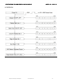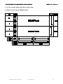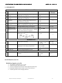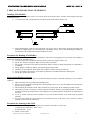
1
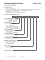
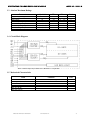
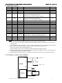
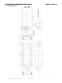
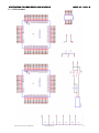
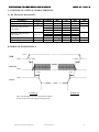
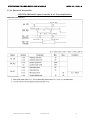
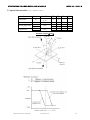
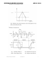
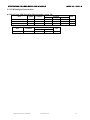
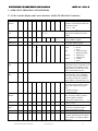
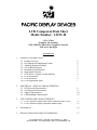
PACIFIC DISPLAY DEVICES LCD Component Data Sheet Model Number: 12232-10 122 x 32 Dot Graphic LCD Assembly With SED1520 / SBN1661G Graphics Controller LED Array Backlight CONTENTS 1. GENERAL INFORMATION 1.1 Product Overview 1.2 Part Options and Numbering System 1.3 Absolute Maximum Ratings 1.4 Circuit Block Diagram 1.5 Mechanical Characteristics 1.6 Input Signal Function 1.7 LCM Power, Contrast Control and Bias 1.8 LCM Dimensions 1.9 LCM Schematic 1.10 LCM Application Notes 2 2 3 3 3 4 4 5 6 7 2. ELECTRICAL / OPTICAL CHARACTERISTICS 2.1 DC Electrical Characteristics 2.2 AC Electrical Characteristics 2.3 Optical Characteristics 2.4 LED Backlight Characteristics 8 9 10 12 3. LCD CONTROLLER CHARACTERISTICS 3.1 LCD Controller Display and Control Functions (SED 1520) 3.2 LCD Controller Display Data Ram Address Map 13 15 4. RELIABILITY 16 5. PRECAUTIONS FOR USING LCD MODULES 17 139 Avenida Victoria – Suite 100 – San Clemente, CA – 92672 Tel: 949-361-8957 – Fax: 949-361-9158 – Web: www.pacificdisplay.com SPECIFICATIONS FOR LIQUID CRYSTAL DISPLAY MODULE MODEL NO: 12232-10 1. GENERAL INFORMATION 1.1 Product Overview • 122 x 32 dot matrix LCD • STN (Super Twisted Nematic) or FSTN (Film compensated Super Twisted Nematic) Technology • Epson SED1520 / Avant SBN1661G / or equivalent Graphics Controller • Multiplex drive : 1/32 duty, 1/6 bias • LCD Module Service Life: 100,000 hours minimum 1.2 Part Options and Numbering System 12232 -10 -SL -F -ST -LED -GY -6 Custom Option Designator: • (-10) SBN1661G or equiv cntlr Interconnection Header Built in Mounting Tabs Operating Mode: • (-SL) STN Silver / Gray • (-GR) STN Green • (-BN) STN Blue Negative Image • (-FC) FSTN: Blk & Wht Image • (-FN) FSTN Neg:. Wht & Blk Image Rear Polarizer Options: • (-F) Transflective • (-M) Transmissive • (-R) Reflective (No Backlight) Operating Temperature: • (-ST) Standard (0 to +50 ºC) • (-ET) Extended (-20 to +70 ºC) Backlight Options: • (-LED) Array Lit LED Backlight Backlight Coloration Options: • (-GY) LED - Green/Yellow • (-AM) LED - Amber • (-WH) ELP – White Viewing Angle: • (-6) 6 o’clock • (-12) 12 0’clock Additional Options: • PACIFIC DISPLAY DEVICES 04.25.2012 2 SPECIFICATIONS FOR LIQUID CRYSTAL DISPLAY MODULE MODEL NO: 12232-10 1.3 Absolute Maximum Ratings Parameter Supply voltage for logic Supply voltage for LCD Input voltage Standard Operating temperature Standard Storage temperature Extended Operating temperature Extended Storage temperature Soldering Temp Symbol Min VDD – VSS VDD - VO VI TOP (-ST) TST (-ST) TOP (-ET) TST (-ET) Tsolder -0.3 – 0.3 -0.3 0 -10 -20 -30 Max 260 6.7 13.0 VDD +0.3 50 60 70 80 Unit V V V ºC ºC ºC ºC ºC 1.4 Circuit Block Diagram Note: Controller chips may be SED-1520 / SBN1661G / or equivalent. 1.5 Mechanical Characteristics Item Module size (W×H×T) Viewing area (W×H) Active area (W×H) Number of dots Dot size (W×H) Dot pitch (W×H) PACIFIC DISPLAY DEVICES Contents 65.1 x 27.1 x 15.1 Max (All configurations) 60.5 x 18.5 53.64 x 15.64 122 x 32 0.4 x 0.45 0.44 x 0.49 04.25.2012 Unit mm mm mm dots mm mm 3 SPECIFICATIONS FOR LIQUID CRYSTAL DISPLAY MODULE 1.6 Input Signal Function Pin No. Symbol Level 1 2 3 4 A0 /CS1 /CS2 CL H/L L L H/L 5 /RD L 6 /WR L 7 8 9 19 11 12 13 14 15 16 VSS DB0 DB1 DB2 DB3 DB4 DB5 DB6 DB7 VDD 0V H/L H/L H/L H/L H/L H/L H/L H/L 5.0V 17 RES HL MODEL NO: 12232-10 Description H : Data signal, L : Instruction signal Chip select signal (Master Controller) Chip select signal (Slave Controller) 2KHz External Clock (-FAA Chip Type) L : Read data bus from controller mode Appropriate /CS line must also be active This is the “R/W” line on the Graphic Controller L : Write data bus to controller mode Appropriate /CS line must also be active This is the ”E” line on the Graphic Controller Ground Data bit 0 Data bit 1 Data bit 2 Data bit 3 Data bit 4 Data bit 5 Data bit 6 Data bit 7 Supply voltage for logic Falling Edge Reset – Selects 8080 Interface Must be left “Low” during normal module operation Input voltage for LCD backplane (Contrast) LED Backlight Anode LED Backlight Cathode Notes* 2 2 5 3, 4 3, 4 3 18 VO --1 19 LED-A 4.2V 20 LED-K 0V *Notes: 1) VO is referenced to both VDD and temperature. See table on page 6 for exact value(s). 2) “/CS1” & “/CS2” tie to the separate /CS pins on the Master & Slave SED-1520 / SBN1661G to be used as the Controller select. The “E” (/WR) line cannot be used as a “E” line in a 6800 implementation since it is common to both controllers. 3) This module can only use the 8080 style interface, and it is set by the state of the reset line. Reset occurs when reset line transitions High to Low. Reset line MUST be left in “Low” signal level condition during normal module operation 4) If /CS1 & /CS2 are both active (high), and /RD line is set to Read (low), damage can occur to module due to bus contention causing serious over-current conditions. 5) External 2KHz clock must be supplied – see SED-1520 / SBN1661G data sheet for clock signal requirements 1.7 LCM Power, Contrast Control and Bias VDD: +5V VDD VR: 20Kohm VO LCM VEE: -5.0V VSS A Backlight Power LED / EL Backlight K PACIFIC DISPLAY DEVICES 04.25.2012 4 SPECIFICATIONS FOR LIQUID CRYSTAL DISPLAY MODULE MODEL NO: 12232-10 1.8 LCM Dimensions PACIFIC DISPLAY DEVICES 04.25.2012 5 SPECIFICATIONS FOR LIQUID CRYSTAL DISPLAY MODULE MODEL NO: 12232-10 1.9 LCM Schematic PACIFIC DISPLAY DEVICES 04.25.2012 6 SPECIFICATIONS FOR LIQUID CRYSTAL DISPLAY MODULE MODEL NO: 12232-10 1.10 LCM Application Notes The Epson SED1520 (or equivalent Avant SBN1661G) is used on many Pacific Display Devices GDM 12232 family modules with 122 segments and 32 commons. Extrapolating the information needed to interface to these ICs on the standard module might be a bit difficult from the Epson documentation. Here is a brief that may speed your progress. Duty Cycle: Set the Duty to 1/32 (D=1). Master / Slave Configuration: The PDD GDM 12232 display family uses the commons from both ICs to form the 32 common rows. Both ICs are used in the active mode. One SED-1520 / SBN1661G will be hardware configured on the PCB as Master by connecting the M/S pin to Vdd. The other controller IC will be hardware configured as Slave by connecting the M/S pin to Vss. With the duty set to 1/32 the master will manage the multiplexing for all 32 commons. Addressing the rows on the SED-1520 / SBN1661G is done by paging. 1 page is 8 bits (or 1 word). The word is written entirely in the same segment (column), but down across 8 commons. Display Writing Example: Starting in the upper left of the display (CS1 (Left Side), Page 0 (First 8 commons), Segment 0), write a full word of data. The data will write to the first column on the display on rows 1 to 8. If one repeats this for all 61 segments, the first page will be full on the left side of the panel. The segment addresses should increment automatically after each write (up till 80), but since there are only 61 segments it will need to be set back to 0 if you are writing in sequence. Apply settings CS1, Page 1, Segment 0 and repeat writing 61 words. Then repeat writing 61 words for CS1 / Page 2 / Segment 0 and CS1 / Page 3 / Segment 0. At this point, the left hand side of the display should be complete. One can repeat the process substituting CS2 (Right Side). PACIFIC DISPLAY DEVICES 04.25.2012 7 SPECIFICATIONS FOR LIQUID CRYSTAL DISPLAY MODULE MODEL NO: 12232-10 2. ELECTRICAL / OPTICAL CHARACTERISTICS 2.1 DC Electrical Characteristics Parameter Symbol Supply voltage for logic Supply current for logic VDD IDD Operating voltage for LCD -ST Version VDD - Vo Operating voltage for LCD -ET Version VDD - Vo Input voltage ' H ' level Input voltage ' L ' level VIH VIL Condition ----0°C 25°C 50°C -20°C 25°C 70°C ----- Min 2.7 --------------0.7 VDD 0 Typ 5.0 0.3 6.9 6.4 6.0 9.2 8.5 7.8 ----- Max 5.5 1.0 ------------VDD 0.3 VDD Unit V mA V V V V ■ TIMING OF POWER SUPPLY 4.75V VDD GND 0~50ms 0~50ms SIGNAL GND ≥ 0ms ≥ 0ms GND VOUT POWER ON POWER OFF Note : The missing pixels may occur when the LCM is driven except above power supply timing sequence. PACIFIC DISPLAY DEVICES 04.25.2012 8 SPECIFICATIONS FOR LIQUID CRYSTAL DISPLAY MODULE MODEL NO: 12232-10 2.2 AC Electrical Characteristics SED-1520/ SBN1661G Graphic Controller IC AC Waveform Interface 8080 Family MPU Selected PACIFIC DISPLAY DEVICES 04.25.2012 9 SPECIFICATIONS FOR LIQUID CRYSTAL DISPLAY MODULE MODEL NO: 12232-10 2.3 Optical Characteristics (VOP = 6.4V, Ta = 25°C ) Item Contrast ratio Frame Frequency Viewing angle range Response time Symbol Cr fFRM θ1 θ2 Ton Toff Condition θ=0° φ=0° --- 25°C 25°C Min Typ Max Unit 3 4 --- --- --0 -30 ----- 60 ----120 200 100 40 30 240 350 Hz deg deg ms ms Definition of angles ∅ and θ: PACIFIC DISPLAY DEVICES 04.25.2012 10 SPECIFICATIONS FOR LIQUID CRYSTAL DISPLAY MODULE PACIFIC DISPLAY DEVICES 04.25.2012 MODEL NO: 12232-10 11 SPECIFICATIONS FOR LIQUID CRYSTAL DISPLAY MODULE MODEL NO: 12232-10 2.4 LED Backlight Characteristics ■ Yellow-Green LED Operating Characteristics (Array Lit) Item Symbol Conditions Forward voltage Forward Current Reverse Voltage Vf IF VR ------- Item Conditions Life Ta= 25 °C PACIFIC DISPLAY DEVICES Min. 3.9 ----- Standard Min. Max. 100,000 --- 04.25.2012 Standard Typ. 4.1 130 --- Max. 4.3 300 8 Unit VDC mA V Unit hrs 12 SPECIFICATIONS FOR LIQUID CRYSTAL DISPLAY MODULE MODEL NO: 12232-10 3. OPERATING PRINCIPALS AND METHODS 3.1 LCD Controller Display and Control Functions (SED-1520/ SBN1661G Controller) Command Display ON/OFF R/W A0 0 0 DB7 DB6 DB5 DB4 DB3 DB2 DB1 DB0 Function 1 0 1 0 1 1 1 0/1 Switches the entire display ON or OFF, regardless of the display RAM抯 data or the internal status. 1 : ON , 0 : OFF *1 Display Start 0 0 1 1 0 Display Start Address Determines the line of RAM data to be Line ( 0 ~ 31 ) displayed at the display抯 top line ( COM0 ). Page Address 0 0 1 0 1 1 1 0 Page Sets the page of the Display RAM in Set (0~3) the Page Address register. Column 0 0 0 Column Address Sets the column of the Display RAM in Address Set ( 0 ~ 79 ) the Column Address register. Status Read 1 0 B A O R 0 0 0 0 Reads status. U D N E BUSY 0 : Ready S C / S 1 : Busy Y O E ADC 0 : Leftward output F T 1 : Rightward output F ON/OFF 0 : Display ON 1 : Display OFF RESET 0 : Normal 1 : Reset Write Display 0 1 Display Data Writes the data on the data bus to Data Display RAM. These commands access a previously-specified address of the display RAM, after which the column address is incremented by one. Read Display 1 1 Display Data Reads the data from the Display RAM Data onto the data bus. These commands access a previously-specified address of the display RAM, after which the column address is incremented by one. ADC Select 0 0 1 0 1 0 0 0 0 0/1 Used to reverse the correspondence between the Display RAM抯 column address and segment driver output ports. 0 : Rightward output 1 : Leftward output Static Drive 0 0 1 0 1 0 0 1 0 0/1 Selects normal display operation or ON/OFF static all-lit drive display operation. 0 : Normal display operation 1 : Static drive ( Power save ) *1 Duty Select 0 0 1 0 1 0 1 0 0 0/1 Select LCD duty cycle. 1: 1/32 , 0: 1/16 Read Modify 0 0 1 1 1 0 0 0 0 0 Increments the column address counter Write by one only when display data is written but not when it is read. End 0 0 1 1 1 0 1 1 1 0 Cancels the Ready Modify Write mode. Reset 0 0 1 1 1 0 0 0 1 0 Resets the Display Start Line to the 1st line in the register. Resets the column address counter to 0 and page address register to 3. *1. Power Save Mode is entered by selecting static drive in the Display OFF status. PACIFIC DISPLAY DEVICES 04.25.2012 13 SPECIFICATIONS FOR LIQUID CRYSTAL DISPLAY MODULE MODEL NO: 12232-10 ■ Initialization PACIFIC DISPLAY DEVICES 04.25.2012 14 SPECIFICATIONS FOR LIQUID CRYSTAL DISPLAY MODULE MODEL NO: 12232-10 3.2 LCD Controller Display Data Ram Address Map ■ DISPLAY DATA RAM ADDRESS MAP PACIFIC DISPLAY DEVICES 04.25.2012 15 SPECIFICATIONS FOR LIQUID CRYSTAL DISPLAY MODULE MODEL NO: 12232-10 4. RELIABILITY No . 1 2 3 4 Test Item High temperature storage Low temperature storage High temperature operation Low temperature operation High temperature / Humidity storage High temperature / Humidity operation 5 6 7 Environmental Test Content of Test Temperature cycle Endurance test applying the high storage temperature for a long time. Endurance test applying the low storage temperature for a long time. Endurance test applying the electric stress (Voltage & Current) and the thermal stress to the element for a long time. Endurance test applying the electric stress under low temperature for a long time. Endurance test applying the high temperature and high humidity storage for a long time. Endurance test applying the electric stress (Voltage & Current) and temperature / humidity stress to the element for a long time. Endurance test applying the low and high temperature cycle. -20°C 25°C 70°C 30min 30min 5min. Test Condition 60 °C 200 hrs -10 °C 200 hrs 50 °C 200 hrs 0 °C 200 hrs 60 °C , 90 %RH 96 hrs 40 °C , 90 %RH 96 hrs -10°C / 60°C 10 cycles Applicable Standard --------------------MIL-202E-103B JIS-C5023 MIL-202E-103B JIS-C5023 ------ 1 cycle Mechanical Test 8 Vibration test Endurance test applying the vibration during transportation and using. 9 Shock test Constructional and mechanical endurance test applying the shock during transportation. 10 Atmospheric pressure test Endurance test applying the atmospheric pressure during transportation by air. 11 Static electricity test Others 10∼22Hz → 1.5mmp-p 22∼500Hz → 1.5G Total 0.5hrs 50G Half sign wave 1l msedc 3 times of each direction 115 mbar 40 hrs Endurance test applying the electric stress to the VS=800V , RS=1.5 kΩ terminal. CS=100 pF 1 time ∗∗∗ Supply voltage for logic system = VDD. Supply voltage for LCD system = Operating voltage at 25°C MIL-202E-201A JIS-C5025 JIS-C7022-A-10 MIL-202E-213B MIL-202E-105C MIL-883B3015.1 ■ LCD Panel Service Life Definition of panel service life • • • • • 100,000 hours minimum at 25° C ±10% Contrast becomes 30% of initial value Current consumption becomes three times higher than initial value Remarkable alignment deterioration occurs in LCD cell layer Unusual operation occurs in display functions PACIFIC DISPLAY DEVICES 04.25.2012 16 SPECIFICATIONS FOR LIQUID CRYSTAL DISPLAY MODULE MODEL NO: 12232-10 5. PRECAUTIONS FOR USING LCD MODULES Installing LCD Modules The hole in the printed circuit board is used to fix LCM as shown in the picture below. Attend to the following items when installing the LCM. 1) Cover the surface with a transparent protective plate to protect the polarizer and LC cell. 2) When assembling the LCM into other equipment, the spacer to the bit between the LCM and the fitting plate should have enough height to avoid causing stress to the module surface, refer to the individual specifications for measurements. The measurement tolerance should be ±0.1mm. Precaution for Handing LCD Modules Since LCM has been assembled and adjusted with a high degree of precision, avoid applying excessive shocks to the module or making any alterations or modifications to it. 1) Cover the surface with a transparent protective plate to protect the polarizer and LC cell. 2) Do not alter, modify or change the shape of the tab on the metal frame. 3) Do not make extra holes on the printed circuit board, modify its shape or change the positions of components to be attached. 4) Do not damage or modify the pattern writing on the printed circuit board. 5) Absolutely do not modify the zebra rubber strip (conductive rubber) or heat seal connector. 6) Except for soldering the interface, do not make any alterations or modifications with a soldering iron. 7) Do not drop, bend or twist LCM. Electro-Static Discharge Control Since this module uses a CMOS LSI, the same careful attention should be paid to electrostatic discharge as for an ordinary CMOS IC. 1) Make certain that you are grounded when handing LCM. 2) Before remove LCM from its packing case or incorporating it into a set, be sure the module and your body have the same electric potential. 3) When soldering the terminal of LCM, make certain the AC power source for the soldering iron does not leak. 4) When using an electric screwdriver to attach LCM, the screwdriver should be of ground potentiality to minimize as much as possible any transmission of electromagnetic waves produced sparks coming from the commutator of the motor. 5) As far as possible make the electric potential of your work clothes and that of the work bench the ground potential. 6) To reduce the generation of static electricity be careful that the air in the work is not too dried. A relative humidity of 50%-60% is recommended. Precaution for soldering to the LCM 1) Observe the following when soldering lead wire, connector cable and etc. to the LCM. a) Soldering iron temperature : 280°C ± 10°C. b) Soldering time : 3-4 sec. 2) Solder : eutectic solder. PACIFIC DISPLAY DEVICES 04.25.2012 17 SPECIFICATIONS FOR LIQUID CRYSTAL DISPLAY MODULE MODEL NO: 12232-10 3) If soldering flux is used, be sure to remove any remaining flux after finishing to soldering operation. (This does not apply in the case of a non-halogen type of flux.) It is recommended that you protect the LCD surface with a cover during soldering to prevent any damage due to flux spatters. 4) When soldering the electroluminescent panel and PC board, the panel and board should not be detached more than three times. This maximum number is determined by the temperature and time conditions mentioned above, though there may be some variance depending on the temperature of the soldering iron. 5) When remove the electroluminescent panel from the PC board, be sure the solder has completely melted, the soldered pad on the PC board could be damaged. Precautions for Operation 1) Viewing angle varies with the change of liquid crystal driving voltage (VO). Adjust VO to show the best contrast. 2) Driving the LCD in the voltage above the limit shortens its life. 3) Response time is greatly delayed at temperature below the operating temperature range. However, this does not mean the LCD will be out of the order. It will recover when it returns to the specified temperature range. 4) If the display area is pushed hard during operation, the display will become abnormal. However, it will return to normal if it is turned off and then back on. Safety • If the LCD panel breaks, be careful not to get the liquid crystal in your mouth. If the liquid crystal touches your skin or clothes, wash it off immediately using soap and plenty of water. Handling • • • • • • • • • • • • The display panel is made of glass. Do not subject it to a mechanical shock by dropping it or impact. If the display panel is damaged and the liquid crystal substance leaks out, be sure not to get any in your mouth. If the substance contacts your skin or clothes, wash it off using soap and water. Do not apply excessive force to the display surface or the adjoining areas since this may cause the color tone to vary. The polarizer covering the display surface of the LCD module is soft and easily scratched. Handle this polarizer carefully. If the display surface becomes contaminated, breathe on the surface and gently wipe it with a soft dry cloth. If it is heavily contaminated, moisten cloth with one of the following solvents : o Isopropyl alcohol o Ethyl alcohol Solvents other than those above-mentioned may damage the polarizer. Especially, do not use the following. o Water o Ketone o Aromatic solvents Exercise care to minimize corrosion of the electrode. Corrosion of the electrodes is accelerated by water droplets, moisture condensation or a current flow in a high-humidity environment. Install the LCD Module by using the mounting holes. When mounting the LCD module make sure it is free of twisting, warping and distortion. In particular, do not forcibly pull or bend the I/O cable or the backlight cable. Do not attempt to disassemble or process the LCD module. NC terminal should be open. Do not connect anything. If the logic circuit power is off, do not apply the input signals. To prevent destruction of the elements by static electricity, be careful to maintain an optimum work environment. o Be sure to ground the body when handling the LCD modules. o Tools required for assembling, such as soldering irons, must be properly grounded. o To reduce the amount of static electricity generated, do not conduct assembling and other work under dry conditions. o The LCD module is coated with a film to protect the display surface. Exercise care when peeling off this protective film since static electricity may be generated. PACIFIC DISPLAY DEVICES 04.25.2012 18 SPECIFICATIONS FOR LIQUID CRYSTAL DISPLAY MODULE MODEL NO: 12232-10 Storage • • • • When storing the LCD modules, avoid exposure to direct sunlight or to the light of fluorescent lamps Store the module in a dark place where the temperature is 25 oC ±10 oC and the humidity below 65% RH. Do not store the module near organic solvents or corrosive gases. Do not crush, shake, or jolt the module (including accessories). Cleaning • • • Do not wipe the polarizing plate with a dry cloth, as it may scratch the surface. Wipe the module gently with soft cloth soaked with a petroleum benzene. Do not use ketonic solvents (ketone and acetone) or aromatic solvents (toluene and xylene), as they may damage the polarizing plate. Others: • • • Liquid crystals solidify under low temperature (below the storage temperature range) leading to defective orientation or the generation of air bubbles (black or white). Air bubbles may also be generated if the module is subject to a low temperature. If the LCD modules have been operating for a long time showing the same display patterns, the display patterns may remain on the screen as ghost images and a slight contrast irregularity may also appear. A normal operating status can be regained by suspending use for some time. It should be noted that this phenomenon does not adversely affect performance reliability. To minimize the performance degradation of the LCD modules resulting from destruction caused by static electricity etc., exercise care to avoid holding the following sections when handling the modules. - Exposed area of the printed circuit board. - Terminal electrode sections. PACIFIC DISPLAY DEVICES 04.25.2012 19