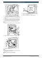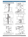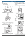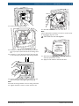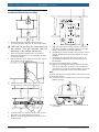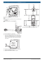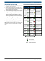
1
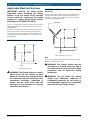
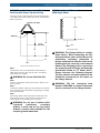
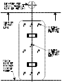
Power Xpress Charge Station
en Installation and Operating Instructions
Technical Support
1-877-805-EVSE (3873)
Copyright © 2013 Bosch Automotive Service Solutions LLC
All rights reserved.
The information, specifications, and illustrations in this guide are based on the latest information available at the time
of printing. Bosch Automotive Service Solutions LLC reserves the right to make changes at any time, without notice.
Installation and Operating Instructions | Power Xpress Charge Station | 1 | en
Table of Contents
Safety2
Regulatory Information
Environmental Considerations Product Specification
FCC Declaration of Conformity Radio and Television Interference Agency Approvals
3
3
3
3
3
3
Features and Specifications
3
Ground-fault protection
3
Automatic reset
3
Ground Assurance Monitoring
3
Self-testing3
Product Features
4
Technical Specifications
4
Package Contents
Optional Kit #1 Contents (EL-50600-2)
Optional Kit #2 Contents (EL-50600-5)
Tools Suggested for Installation
Possible Materials Needed
5
5
5
5
5
Applicable Electrical Systems
220/240V Single Phase (North America)
208V 3-Phase Wye Connection (North America)
240V 3-Phase Delta Connection (North America)
230V Above Ground (Europe) 230V Single Phase
6
6
6
7
7
Electrical Requirements for Battery Charging
8
Amperage and Breaker Parameters
8
Charge Station Mounting Instructions
Mounting Template
Finished Wall Charge Station Installation
Masonry Wall Charge Station Installation
Molded Plug-Connected Charge Station Installation
8
8
9
13
16
Operating Instructions
Power and Status LED Indications
19
19
Troubleshooting20
Ground Fault Circuit Interrupt (GFCI) Tripped
20
Missing Ground
20
Maintenance21
Cleaning21
Storage and Moving
21
Limited Warranty
22
Disclaimer22
Legal Limitation of Liability
22
Copyrights, Trademarks
22
Bosch Automotive Service Solutions LLC
EL-50600-7-2 | REV. B | 20.10.2013
en | 2 | Installation and Operating Instructions | Power Xpress Charge Station
Safety
Save these instructions. Read all instruction before
installing or using the Power Xpress Charge Station.
WARNING: Turn OFF the circuit breaker
at the service or distribution panel before
performing any electrical work or repairs.
WARNING: The Charge Station must
be installed by a licensed electrician in
accordance with all local electrical codes,
ordinances, and all authorities having
jurisdiction.
WARNING: Do not install the Charge
Station near flammable, explosive, or
combustible materials. Do not locate or
store flammable, explosive, or combustible
materials near the Charge Station.
WARNING: The Charge Station contains
no user-serviceable parts. Do not attempt
to repair or service the Charge Station
yourself. If the Charge Station requires
servicing, contact Bosch.
WARNING: Adult supervision is required
when using the Charge Station around
children.
WARNING: Do not put flngers into the
Charge Station electric vehicle connector.
WARNING: Disconnect main service power
to the Charge Station before cleaning the
unit. Do not use cleaning solvents to clean
any part of the Charge Station. Clean
enclosure, cable and connector with a
clean, dry cloth to remove dust and dirt
accumulation.
WARNING: If the device repeatedly trips,
seek advice from Bosch.
WARNING: Use/operate Charge Station:
(1) In a well-lit area and away from high
pedestrian traffic to avoid accidental
tripping hazard. (2) away from areas of
child activity to avoid potential shock
hazards.
EL-50600-7-2 | REV. B | 20.10.2013
WARNING: Disconnect main service
supply or unplug unit to achieve electrical
isolation.
WARNING: Do not tamper with or modify
this device.
WARNING: If Charge Station fails to
operate correctly in accordance with the
operation manual, do not use this device.
Contact Bosch for repair or replacement.
WARNING: Improper installation of the
Charge Station can result in personal
injury or product damage.
WARNING: This Charge Station installation
guide is not a substitute for electrical
safety precautions.
WARNING: Use this Charge Station within
the specified operating parameters. Failure
to do so may result in injury or death.
WARNING: Locate and install this Charge
Station in a location where the charge
cable will not be stepped on, tripped over,
or subject to damage or stress.
WARNING: The Charge Station must
be connected to a grounded, metal,
permanent wiring system, or an equipmentgrounding conductor must be run with
the circuit conductors and connected to
the equipment grounding terminal on the
Charge Station.
CAUTION: Incorrect installation of the
Charge Station can result in damage to the
vehicle’s battery and to the Charge Station
itself. These damages will void the warranty
for the vehicle and the Charge Station.
CAUTION: Do not operate the Charge Station
in temperatures beyond its operating range
of -40°F to +122°F (-40°C to +50°C).
Bosch Automotive Service Solutions LLC
Installation and Operating Instructions | Power Xpress Charge Station | 3 | en
Regulatory Information
Features and Specifications
At the end of service life, the Charge Station
should be recycled according to local laws and
regulations.
The Charge Station includes ground-fault protection,
automatic reset upon grid power loss, ground assurance
monitoring, and self-testing capabilities. Manual resetting of the Charge Station is not necessary. Exception:
European models require manual resetting after ground
fault condition.
Product Specification
Ground-fault protection
All Charge Station specifications and descriptions are
accurate at the time of this document’s printing. We
always strive to constantly improve and update our
products, Bosch reserves the right to make changes at
any time, without notice and without obligation.
Continually provides a safe power supply to the vehicle.
If a ground fault is present, the Charge Station detects it
and cuts power flow, protecting people and the vehicle
from an electric shock hazard.
Environmental Considerations
FCC Declaration of Conformity
This device complies with Part 15 Class-B of the
FCC rules. Operation is subject to the following two
conditions: 1) This device may not cause harmful interference, and 2) this device must accept any interference
received, including interference that may cause undesired operation.
Note:
Non-authorized changes or modifications to this product could void its FCC compliance.
Radio and Television Interference
The equipment described in this manual has been
designed to protect against Radio Frequency Interference (RFI). However, there are some instances where
high-powered radio signals or nearby RF-producing
equipment (such as digital phones, RF communications
equipment, etc.) could affect Charge Station operations. If interference to the Charge Station occurs during charging, contact Bosch.
Agency Approvals
Standard Compliances through a National Registered
Testing Lab (NRTL)
North American Operation
FCC Part 15 Class-B
UL 2594
UL 2251
UL 62
UL 60950-1
UL 1998
UL 2231-1 & -2
CSA C22.2 #60950-1
CSA C22.2 #107.1
SAE J1772
NEC Article 625
Automatic reset
If main line side power supply is interrupted during
charging, the Charge Station will reset itself automatically and re-attempt charging after main line side power
supply is restored.
If the problem is associated with a ground fault, the
Charge Station makes a total of 4 automatic reset attempts in sequential 15-minute periods. If the charging
mode can not be restored, the appropriate failure indication will be shown on the unit’s front panel. NOTE: Not
applicable on European models; European models require pressing of the master clear “Reset” button on the
front panel of the Charge Station to restore power.
See Table-A in Operating Instructions for LED status indications (page 11).
The automatic reset feature assures that your vehicle will
be charged and ready to use by automatically restoring
power after temporary interruptions (grid-power outages, temporary ground faults [US models only] and
power surges).
Ground Assurance Monitoring
A proper electrical ground is critical to reliable groundfault protection, the Charge Station includes a ground
monitoring circuit to assure presence of a safe electrical
ground.
Self-testing
To assure proper functionality and safety, the Charge
Station includes self-testing and diagnostics circuitry,
which is automatically performed prior to each charging
cycle.
European Union Operation
IEC 61851-1
IEC 61851-21 & -22
IEC 60950-1
IEC 61000-6-1 EMC Immunity
IEC 61000-6-3 EMC Emissions
IEC 62196 Coupler, Type 1, Type 2
IEC 60204-1, Safety for servicing electronic equipment
Bosch Automotive Service Solutions LLC
EL-50600-7-2 | REV. B | 20.10.2013
en | 4 | Installation and Operating Instructions | Power Xpress Charge Station
Product Features
Voltage and
Wiring
(120V above
ground)
•
240VAC single-phase: L1, L2, and
safety ground. •
•
Output
Amperage
208VAC 3-phase, wye-connected:
Any 2 phases and safety ground.
•
Technical Specifications
32A Max, Model Dependent
(see output spec. label on side of
Charge Station)
175 VAC – 264 VAC
nected: with center tap on one
Input
Voltage
Range
leg, use only the two phases on
Frequency
50/60Hz
either side of the center tap. The
Ground
Fault Trip
Level
17.5 mA (20mA Max)
Ground
Assurance
50K ohm Max (North American),
240VAC 3-phase, delta-con-
two phases must both measure
120V AC to ground. Do not use
the third leg (208V “stinger”)
Voltage and
Wiring
(230V above
ground
- Europe)
230V AC single-phase:
LINE, NEUTRAL, and EARTH
Current and
Frequency
Current—Model dependent; see unit
specification label
50/60Hz
Surge
Protection
100K ohm Max (Europe)
6kV @3000A
Operating
Humidity
Up to 95% non-condensing
@1060hPa
Operating
Temperature
-40°F to +122°F (-40°C to +50°C)
Storage
Temperature
-58°F to +176°F (-50°C to +80°C)
Ground Fault
Test
Automatic at startup (Firmware controlled)
(132 mm) width × 4.3 in. (109.2) depth
Ground Fault
Retry
Weight
Approximately 16 pounds w/25 ft
(7.6 m) cable and coupler
4 automatic retries @ 15 min. intervals (per UL2231-2)–not applicable to
European models
Master Clear
For System Reset
Operating
Temperature
Storage
Temperature
-40°F to +122°F (-40°C to +50°C)
-58°F to +176°F (-50°C to +80°C)
Ratings and
Agency
Approvals
Enclosure Type NEMA 4X –
indoor/outdoor use, watertight
• ETL approved to UL and CSA
standards•
• CE compliant w/3rd-Party ETL
testing•
• FCC Part 15 Class-B compliant
Cable
Length and
Connector
Maximum 25 ft (7.6 m) per NEC 625
—Model dependent; see unit specification label (18 ft (5.5 m) typical)
Dimensions
14.5 in. (368.3 mm) height × 5.2 in.
EL-50600-7-2 | REV. B | 20.10.2013
(Overrides Ground Fault Retry and all
other fault conditions)
Power
Indication
Green LED
Charge
Status
Indicators
•
Amber (Ready)
•
Green (Plugged In)
•
Green Flashing (Charging)
Enclosure
• Red Flashing (Fault)
NEMA 4X & per UL 50E
Bosch Automotive Service Solutions LLC
Installation and Operating Instructions | Power Xpress Charge Station | 5 | en
Package Contents
(1) Charge Station (including attached cord and vehicle
coupler) (EL-50600-1)
(1) Wall-mounting bracket (EL-50600-1)
(1) User Manual (EL-50600-7-2)
(1) Wiring chamber cover (EL-50600-3)
(1) Wiring chamber cover label (EL-50600-3)
(4) 3/4-in. (20-mm) No.2 square-drive screws (EL50600-5)
(1) Rubber grommet (EL-50600-4)
(1) Foam dust cover gasket (EL-50600-4)
(1) 3/4-in. (20-mm) plastic bushing (EL-50600-4)
(1) Small sealing plug (EL-50600-4)
(1) Knockout plug
Optional Kit #1 Contents (EL-50600-2)
(1) Primary-side, 12-in. (305-mm) cable w/molded
NEMA 6-30 plug
(1) 3/4-in. (20-mm) NPT cable gland with nut and sealing washer
Optional Kit #2 Contents (EL-50600-5)
(6) #8 × 1 1/4-in. (32-mm) Phillips pan-head screws
with plastic drywall anchors
(3) 3/16 × 1 1/4-in. (5 × 32-mm) Phillips tapered-head
masonry fastener screws
Bosch Automotive Service Solutions LLC
Tools Suggested for Installation
Stud finder
Tape measure
2-ft (61-cm) level
Chalk line
Pencil
Power drill
#2 Phillips screwdriver
#2 square-head screwdriver
3/16-in. (5-mm) flat-blade screwdriver
3/32-in. (2.5-mm) flat-blade screwdriver
NM (non-metallic) wire stripper
Wire cutters
Wire stripper
Needle-nose pliers
Hammer
Clear silicone
1/16-in. (2-mm) drill bit
1 1/16-in. (28-mm) hole-saw
1/8-in. (4-mm) masonry drill bit
3/16-in. (5-mm) drill bit
Torque screwdriver with #2 Phillips-head bit and 3/16-in.
(5-mm) slotted-head bit
Possible Materials Needed
(dependent upon installation type; not provided)
90° Fitting for liquid-tight flex conduit
Male threaded EMT fitting with offset; 3/4-in. (20-mm)
Locking nut for 3/4-in. (20-mm) male EMT with binding
screw
Sealing gasket for 3/4-in. (20-mm) male EMT fitting
Male threaded PVC fitting; 3/4-in. (20-mm)
Locking nut for 3/4-in. (20-mm) male PVC fitting
Sealing gasket for 3/4-in. (20-mm) male PVC fitting
PVC jake offset; 3/4-in. (20-mm)
PVC coupler; 3/4-in. (20-mm)
NM, UF, or 3G wire
EL-50600-7-2 | REV. B | 20.10.2013
en | 6 | Installation and Operating Instructions | Power Xpress Charge Station
Applicable Electrical Systems
IMPORTANT: Identify the onsite service
connection before insthalling the Charge
Station. If you are unsure of the available
service connection, consult the local utility
company or contact Bosch Electric Vehicle
Solutions at 1-877-805-EVSE (3873).
208V 3-Phase Wye Connection (North
America)
Any two of the legs can be used to provide 208V to the
Charge Station with a Wye-connected secondary. For
example, L1 and L2, or L1 and L3, or L2 and L3. Reference the wiring diagram below.
L3 (NOT USED)
The L1, L2, and Ground outputs (H, N for Europe) in the
followingillustrations correspond to the inputs on the
Charge Station.
For the (earth) ground connection, always connect the
neutral at the service panel to earth ground. Ground
fault protection is not possible unless the neutral (center tap on the service transformer) is connected to an
earth ground.
220/240V Single Phase (North America)
L1
120V
NEUTRAL
(NOT USED)
120V
L1
L2
120V
GND
NEUTRAL
(NOT USED)
240V
208V 3-Phase Wye Connection
120V
L2
220/240V Single Phase
WARNING: The Charge Station is a singlephase device. Do not connect all three
phases of a 3-phase feed. Only three wires
are connected, take care that the service
transformer secondary connection is
known, and the three wires from the
main-panel circuit breaker are correctly
connected and labeled.
EL-50600-7-2 | REV. B | 20.10.2013
Note:
A current-carrying neutral is not required for the Charge
Station for 208V connections.
WARNING: The Charge Station must be
installed by a licensed electrician and in
accordance with all local electrical codes,
ordinances, and all authorities having
jurisdiction.
WARNING: Do not install the Charge
Station near flammable, explosive, or
combustible materials. Do not locate or
store flammable, explosive, or combustible
materials near the Charge Station.
Bosch Automotive Service Solutions LLC
Installation and Operating Instructions | Power Xpress Charge Station | 7 | en
240V 3-Phase Delta Connection (North
America) with Center Tap on One Leg
230V Above Ground (Europe)
230V Single Phase
One leg must be center-tapped, and only the two phases on either side of the center tap can be used with the
delta connection.
LINE (H)
L3 (NOT USED)
230VAC
L1
L2
CENTER TAP
L1
120V
NEUTRAL (N)
NEUTRAL
(NOT USED)
240V
EARTH
230V Single Phase
120V
L2
GND
240V 3-Phase Delta Connection
Note:
The third line (L3 on the illustration of the delta) is
208V, with respect to the neutral, and is sometimes
referred to as a “stinger.”
WARNING: Do not use this third line.
Note:
The two used phases must each measure 120V to neutral or ground.
Note:
Consult the utility company or the transformer manufacturer’s literature to verify that the single leg can supply
the required power.
WARNING: The Charge Station is a singlephase device. When connecting the line
and neutral wires, take care that the service
transformer secondary connection is
known, and the wires from the main circuit
breaker panel are correctly connected and
labeled. The following service connections
are primarily used in Europe and Australia
(sometimes known as “TT Power Grid”).
Please reference the following diagram.
The line, neutral, and earth outputs on the
illustration correspond to the inputs on
the Charge Station.
WARNING: The line connection must
measure 230V RMS to neutral. Earth must
also be connected to the Charge Station.
Note:
The Charge Station will only operate properly if it detects the presence of a ground wire connected to a
neutral point on the transformer secondary.
WARNING: Do not use a 3-phase deltaconnected
transformer
secondary
without a center tap on one leg and/or
without a neutral point available for the
required ground connection.
Bosch Automotive Service Solutions LLC
EL-50600-7-2 | REV. B | 20.10.2013
en | 8 | Installation and Operating Instructions | Power Xpress Charge Station
Electrical Requirements for
Battery Charging
WARNING: The Charge Station must
be installed by a licensed electrician
in accordance with all national and
local
electrical
codes,
ordinances,
requirements, and all authorities having
jurisdiction.
CAUTION: The AC electrical connection
must have a grounded, dedicated servicemain. No other loads shall be connected to
the same circuit. Use of a non-dedicated
circuit could exceed the current rating of
the circuit breaker and cause it to trip or
open.
CAUTION: Do not use portable or stationary
backup generating equipment to charge
the vehicle. This may cause damage to the
vehicle’s charging system. Only charge the
vehicle from utility-supplied power.
Amperage and Breaker
Parameters
Note:
The Charge Station has been factory set at 30-amp
output for a 40-amp circuit. For all other amperages:
1. Remove the domed cap from the current-adjustment selector (positioned just above the reset
button on the front of the Charge Station).
Table 1. North American Current-Adjustment Settings
Charge
Station
CurrentAdjustment
Setting
Charge
Station
Output,
Amp
Breaker
Required,
Amp
Wire
Required,
Gauge
NEMA
Receptacle
Required
(plug-in
version)
1
2
3
4
5
12
16
24
32
30
15
20
30
40
40
12
12
10
8
8
6-15
6-20
6-30
6-50
6-50
Table 2. European Current-Adjustment Settings
Charge
Station
CurrentAdjustment
Setting
Charge
Station
Output,
Amp
Breaker
Required,
Amp
Wire
Required,
mm2
1
2
3
4
5
13
16
20
32
30
16
20
20*
40
40
3.31
3.31
5.26
8.36
8.36
*Line service breaker; not appliance service breaker
Note:
Only settings 1–5 are operational. Settings 6, 7, 8, 9, and
0 are not used, and the Charge Station will not function
under these settings.
Charge Station Mounting
Instructions
WARNING: Read all instructions before
installing the Charge Station.
Identify an approximate mounting location for the Charge
Station that is within 10 feet (3 m) of the vehicle‘s charging inlet.
Determine the power source location.
CAUTION: Verify there is no existing
infrastructure behind the selected wall
(wiring, plumbing, ductwork, pipes, etc.)
Follow the appropriate instructions for your installation:
2. Using a small, flat-blade screwdriver, set the current-adjustment selector to the applicable output
current-limiting setting, as indicated in Table 1 or
Table 2.
EL-50600-7-2 | REV. B | 20.10.2013
•
“Finished Wall Charge Station Installation” on page
9
•
“Masonry Wall Charge Station Installation” on page
13
•
“Molded Plug-Connected Charge Station Installation
(North America only)” on page 16
Note:
If wall surface is unfinished (studs only), mount a 36 ×
17.5 × 3/8-in. (90 × 45 × 1-cm) plywood surface between
the studs and securely fasten in place. Follow “Finished
Wall Charge Station Installation” for mounting and “Masonry Wall Charge Station Installation” for wiring.
Bosch Automotive Service Solutions LLC
Installation and Operating Instructions | Power Xpress Charge Station | 9 | en
ss01412
Mounting Template
See the back cover of this manual for the Charge Station mounting template.
Finished Wall Charge Station Installation
ss01410
4. Align the hash-marked center and lower horizontal
lines of the template to the lines drawn on the wall.
Adhere the template to the wall with tape.
39
3
ss01413
1. Using a stud finder and tape measure, locate and
mark a point equidistant between vertical studs
and 45 in. (114.3 cm) above the floor surface.
ss01411
5. Using a 3/16-in. (5-mm) drill bit, drill the six (6)
holes marked „B“ on the template.
ss01414
2. From this point, use a level to draw a true vertical
line and a true horizontal line on the wall.
3. Retrieve the mounting template on the back cover
of this manual.
6. Using a 1 1/16-in. (28-mm) hole saw, drill a wiringaccess hole at the location indicated at the top of
the template.
Bosch Automotive Service Solutions LLC
EL-50600-7-2 | REV. B | 20.10.2013
en | 1 0 | Installation and Operating Instructions | Power Xpress Charge Station
Note:
To avoid damage to the front of the Charge Station,
place it on a soft or cardboard surface.
ss01415
ss01419
7. Remove the template from the wall. Using a hammer, install a plastic drywall anchor in each of the
six (6) „B“ holes.
Note:
Charge Station support-strength requirement is based
on a minimum 3/8-in. (1-cm) drywall thickness
10. Drill a pilot hole in the center of the rear knockout
on the Charge Station unit.
ss01420
ss01417
11. Using a 1 1/16-in. (28-mm) hole saw, with the pilot
hole as a guide, drill out the rear knockout.
8. Align mounting plate with installed plastic anchors
and secure with six (6) #8 pan-head screws.
CAUTION: Use a mid-range speed setting
and drill carefully to avoid punching through
housing and damaging internal components.
12. Remove debris from wiring chamber.
ss01418
ss01421
9. Feed sufficient wire from the service panel through
the wire-access hole to make connections to the
Charge Station terminal block.
EL-50600-7-2 | REV. B | 20.10.2013
13. For indoor installation, assemble the plastic holebushing into the knockout and firmly snap into place.
Bosch Automotive Service Solutions LLC
Installation and Operating Instructions | Power Xpress Charge Station | 11 | en
ss01429
ss01423
L2/N
18. Remove the strain-relief assembly from the wiring
chamber.
14. Cover the plastic bushing with the self=adhesive
foam dust-cover gasket, with the center-slit oriented
horizontally.
ss01430
ss01425
19. Trim the wire to a length sufficient to make the
connections to the Charge Station terminal block.
ss01431
15. For outdoor installation, assemble the rubber
grommet into the knockout and snap into place.
16. Feed the wire from the service panel, through the
dust cover or grommet, and into the Charge Station
ss01426
wiring chamber.
20. Strip back 1 1/4 in. (32 mm) of the wire jacket and
3/8 in. (10 mm) from the ends of the individual
conductors.
ss01432
L2/N
17. Secure the Charge Station to the mounted wall bracket by engaging the tabs on the Charge Station into the
slots on the wall bracket. Press firmly and slide the
Charge Station down until fully seated on the bracket.
Bosch Automotive Service Solutions LLC
21. Remove threaded ground lug.
EL-50600-7-2 | REV. B | 20.10.2013
en | 1 2 | Installation and Operating Instructions | Power Xpress Charge Station
ss01443
ss01434
L1
L2/N
27. Attach the wiring chamber lid with four (4) 3/4-in.
(20-mm) square-drive screws.
28. Apply the self-adhesive chamber lid label.
22. Feed the L1 (black) [Europe H (brown)] wire into
the L1 [Europe H] terminal slot in the wiring chamber.
23. Feed the L2 (red) [Europe N (blue)] wire into the
L2 [Europe N] terminal slot in the wiring chamber.
24. Attach safety ground wire through the slot on the
ground terminal. Hand-tighten grounding lug.
Note:
See inside of wiring chamber cover for wiring schematic.
25. Tighten terminal screws to 1.2 Nm (10.62 in-lb).
ss01438
26. Reinstall strain relief.
Note:
Select appropriate orientation of insert to achieve proper clamping for wire size used.
CAUTION: Do not overtighten.
EL-50600-7-2 | REV. B | 20.10.2013
Bosch Automotive Service Solutions LLC
Installation and Operating Instructions | Power Xpress Charge Station | 13 | en
ss01451
Masonry Wall Charge Station Installation
ss01453
1. Locate and mark a point 45 in. (114.3 cm) above
the floor surface.
ss01448
2. From this point, use a level to draw a true vertical
line and a true horizontal line on the wall.
3. Retrieve the mounting template on the back cover
of this manual.
5. Using a 1/8-in. (3-mm) drill bit, drill the three (3)
holes marked „A“ on the template.
6. Select a location on the template for entry of conduit
into the Charge Station (top, upper left, or upper right).
7. Snap a chalk line from the appopriate level line on the
template in the direction of the incoming conduit.
8.ss01454
Remove the template from the wall.
ss01412
4. Align the hash-marked center and lower horizontal
lines of the template to the lines drawn on the wall.
Adhere the template to the wall with tape.
Bosch Automotive Service Solutions LLC
9. Align the mounting plate with the „A“ holes in the
wall and secure with three (3) 3/16-in. (5-mm) tapered-head masonry screws.
EL-50600-7-2 | REV. B | 20.10.2013
en | 1 4 | Installation and Operating Instructions | Power Xpress Charge Station
15. Secure the Charge Station to the mounted wall
bracket by engaging the tabs on the Charge Station
into the slots on the wall bracket. Press firmly and
slide the Charge Station down until fully seated on
the bracket.
16. Feed the wire from the service panel through the
conduit and into the Charge Station wiring chamber.
Note:
To avoid damage to the Charge Station, place it on a
soft or cardboard surface.
10. Locate the desired conduit-entry point on the
Charge Station housing.
ss01459
ss01455
11. Drill a pilot hole in the center of the selected knockout location.
17. Attach
offset conduit to NPT female adaptor.
ss01429
1456
L2/N
12. Using a 1 1/16-in. (28-mm) hole saw, with the pilot
hole as a guide, drill out the knockout.
18. Remove the strain-relief assembly from the wiring
chamber.
ss01430
CAUTION: Use a mid-range speed setting
and drill carefully
to avoid punching
POWER
through housing and damaging internal
STATUS
components.
13. Remove debris from wiring chamber.
ss01431
14. Install a 3/4-in. (19-mm) NPT female adaptor with
nut and seal into the knockout and tighten securely.
EL-50600-7-2 | REV. B | 20.10.2013
19. Trim the wire to a length sufficient to make the connections to the Charge Station terminal block.
20. Strip back 1 1/4 in. (32 mm) of the wire jacket and 3/8
in. (10 mm) from the ends of the individual conductors.
Bosch Automotive Service Solutions LLC
Installation and Operating Instructions | Power Xpress Charge Station | 15 | en
ss01432
ss01438
L2/N
21. Remove threaded ground lug.
ss01434
26. Reinstall strain relief.
Note:
Select appropriate orientation of insert to achieve proper clamping for wire size used.
CAUTION: Do not overtighten.
L1
L2/N
ss01443
22. Feed the L1 (black) [Europe H (brown)] wire into
the L1 [Europe H] terminal slot in the wiring chamber.
23. Feed the L2 (red) [Europe N (blue)] wire into the
L2 [Europe N] terminal slot in the wiring chamber.
27. Attach the wiring chamber lid with four (4) 3/4-in.
(20-mm) square-drive screws.
28. Apply the self-adhesive chamber lid label.
24. Attach safety ground wire through the slot on the
ground terminal. Hand-tighten grounding lug.
Note:
See inside of wiring chamber cover for wiring schematic.
25. Tighten terminal screws to 1.2 Nm (10.62 in-lb).
Bosch Automotive Service Solutions LLC
EL-50600-7-2 | REV. B | 20.10.2013
en | 1 6 | Installation and Operating Instructions | Power Xpress Charge Station
Molded Plug-Connected Charge Station
Installation (North America only)
ss01478
1. Install appropriate outlet box (ground-pin at
12-o’clock position) with top- or side-conduit feed.
CAUTION: Do not feed the outlet box from
the bottom. This will interfere with the
mounting of the Charge Station unit.
2. Place the outlet box between two (2) studs for
finished-wall installation or any applicable location
for masonry walls.
3. Install outlet box 61 in. (155 cm) from floor surface
to the bottom of the outlet box.
7. Align the hash-marked center and lower horizontal
lines of the template to the lines drawn on the wall.
Adhere the template to the wall with tape.
8. If installing on a masonry wall, using a 1/8-in. (3-mm)
drill bit, drill the three (3) holes marked „A“ on the
template.
9. If installing on a finished wall, using a 3/16-in. (5mm) drill bit, drill the six (6) holes marked „B“ on
the template.
10. Remove the template from the wall.
11. Align the mounting plate with the holes in the wall
and secure with three (3) 3/16-in. (5-mm) taperedhead masonry screws for masonry walls or six (6) #8
pan-head screws with anchors for finished walls.
Note:
To avoid damage to the Charge Station, place it on a soft
or cardboard surface.
12. Locate the desired conduit-entry point on the Charge
Station housing.
ss01474
ss01455
4. Locate and mark a point 16 in. (40.6 cm) down
from the bottom-center of the outlet box.
13. Drill a pilot hole in the center of the selected knockout location.
5. From this point, use a level to draw a true vertical
line and a true horizontal line on the wall.
6. Retrieve the mounting template on the back cover
of this manual.
EL-50600-7-2 | REV. B | 20.10.2013
Bosch Automotive Service Solutions LLC
Installation and Operating Instructions | Power Xpress Charge Station | 17 | en
ss01456
ss01432
L2/N
19. Remove threaded ground lug.
ss01434
14. Using a 1 1/16-in. (28-mm) hole saw, with the pilot
hole as a guide, drill out the knockout.
CAUTION: Use a mid-range speed setting
and drill carefully
to avoid punching
POWER
through housing and damaging internal
STATUS
components.
ss01481
15. Remove debris from wiring chamber.
L1
16. Install the 3/4-in. (19-mm) cable gland adaptor with
nut and O-ring into drilled 1 1/16-in. (28-mm) hole
in the Charge Station. Securely tighten.
17. Assemble the 3/4-in. (19-mm) cable gland cap to
the
molded plug/cable assembly.
ss01429
L2/N
20. Feed molded plug/cable/cable gland assembly
through the 1 1/16-in. (28-mm) hole in the housing
and orient the conductor wire to the terminal block.
Remove strip/retain insulation ends.
L2/N
L1
L2/N
ss01487
18. Remove the strain-relief assembly from the wiring
chamber.
21. Feed the L1 (black) [Europe H (brown)] wire into
the L1 [Europe H] terminal slot in the wiring chamber.
22. Feed the L2 (red) wire into the L2 terminal slot in
the wiring chamber.
23. Attach safety ground wire through the slot on the
ground terminal. Hand-tighten grounding lug.
Note:
See inside of wiring chamber cover for wiring schematic.
24. Tighten terminal screws to 1.2 Nm (10.62 in-lb).
Bosch Automotive Service Solutions LLC
EL-50600-7-2 | REV. B | 20.10.2013
en | 1 8 | Installation and Operating Instructions | Power Xpress Charge Station
ss01496
ss01438
25. Reinstall strain relief.
Note:
Select appropriate orientation of insert to achieve proper clamping.
ss01491
CAUTION: Do not overtighten.
30. Plug Charge Station plug into NEMA outlet.
26. Securely tighten the cable gland.
27. Secure the Charge Station to the mounted wall
bracket by engaging the tabs on the Charge Station
into the slots on the wall bracket. Press firmly and
slide the Charge Station down until fully seated on
the bracket.
ss01443
28. Attach the wiring chamber lid with four (4) 3/4-in.
(20-mm) square-drive screws.
29. Apply the self-adhesive chamber lid label.
EL-50600-7-2 | REV. B | 20.10.2013
Bosch Automotive Service Solutions LLC
Installation and Operating Instructions | Power Xpress Charge Station | 19 | en
Operating Instructions
1. Verify service supply power is available; green POWER indicator LED is illuminated.
Power and Status LED Indications
Power LED
2. Retrieve Charge Station vehicle cable and coupler
from rear-mounted holder (stowed position); amber
STATUS indicator light is illuminated.
Status LED
(Off)
No service supply
power
Green
solid
Amber solid
Charge Station
powered; vehicle
coupler not
connected
Green
solid
Green solid
Waiting to charge
Green
solid
Green
flashing
Vehicle charging
Green
solid
1–2 red
flashes
every 2
seconds
Pilot charging
error*
Green
solid
Solid red,
then green
flash every
2 seconds
Ground fault
detected*
Green
solid
Red
flashing
Ground monitor
interrupted*
Green
solid
Red solid
Operation fault*
Green
solid
(Off)
Operation fault*
(Off)
3. Connect Charge Station coupler to vehicle; STATUS
indicator LED changes to solid green.
4. Charge Station performs safety self-test (audible
mechanical clicking sounds); STATUS indicator
begins to flash green, indicating vehicle is charging
(vehicle may indicate charging with an audible
signal or a light indicator; varies by vehicle model).
When charge is complete, the STATUS LED will
change from flashing green to solid green.
5. Disconnect Charge Station coupler from vehicle;
STATUS indicator changes to amber.
6. Return cable and coupler to rear-mounted holder
(stowed position) at Charge Station unit.
Note:
Charge Station will automatically resume charging upon
restoration of lost service-supply power (US models
only).
Condition
*See “Troubleshooting” on page 20 for suggested
solutions.
Bosch Automotive Service Solutions LLC
- No illumination
- Solid illumination
- Flashing illumination
EL-50600-7-2 | REV. B | 20.10.2013
en | 2 0 | Installation and Operating Instructions | Power Xpress Charge Station
Troubleshooting
If there is a charging issue proceed with the following
steps. If the issue persists after three attempts call
Bosch at 1-877-805-EVSE (3873) for assistance.
Problem
Indicated
by LED
Status
Solution
Solution
Operation
fault
1.
2.
Pilot charg- 1.
ing error
2.
3.
Ground
fault
detected
Problem
Indicated
by LED
Status
1.
2.
3.
4.
5.
Ground
1.
monitor
interrupted 2.
3.
4.
5.
Verify supply-side power. The green
POWER LED should be on. If green
POWER LED is off, locate load
center/panel and reset breaker.
Press the master clear RESET button
on the front panel of the Charge
Station to attempt a charge-restart.
If the red STATUS LED remains
on, disconnect the Charge Station
coupler from the vehicle charge port,
wait 10 seconds, and reconnect the
coupler.
Disconnect main service power at
service panel.
Disconnect the Charge Station
coupler from the vehicle.
Inspect
the
Charge
Station
connector and the vehicle charge
port verifying both are clean and
undamaged. If vehicle charge port
needs cleaning, follow manufacturer
instructions for cleaning. Clean
Charge Station connector with a dry
or damp cloth if necessary.
Restore main service power.
Reconnect the coupler to the vehicle
port.
EL-50600-7-2 | REV. B | 20.10.2013
3.
Verify supply-side power. The green
POWER LED should be on. If green
POWER LED is off, locate load
center/panel and reset breaker.
Press the master clear RESET button
on the front panel of the Charge
Station to attempt a charge-restart.
If the red STATUS LED remains
on, disconnect the Charge Station
coupler from the vehicle charge port,
wait 10 seconds, and reconnect the
coupler.
Ground Fault Circuit Interrupt (GFCI) Tripped
If the Charge Station detects a ground fault, power will
be interrupted and the STATUS LED will illuminate (red
flash with intermittent green). The Charge Station will
attempt to reset automatically and re-attempt charging
(see note below on European models). If the fault condition persists after an initial automatic attempt, per the
code, the Charge Station waits 15 minutes before a
second attempt is made. A total of four attempts will be
made to restore vehicle charging. If the charging mode
cannot be restored, the STATUS LED will illuminate solid
red, and the unit will stay in fault mode.
Note:
European models—Automatic reset feature after ground
fault (STATUS LED will be solid red) does not apply to
European models. European standards dictate that user
intervention is required by pressing the master clear
RESET button on the front of the Charge Station housing.
If ground fault condition clears, Charge Station will resume charging.
Missing Ground
If the Charge Station detects a missing ground connection (rapid red flashing LED), power will be interrupted
and the unit will not be capable of charging vehicle until
a ground connection has been detected. Disconnect
service power (breaker) and disconnect vehicle coupler
from vehicle and contact a qualified Bosch technician to
validate the presence of a proper ground.
Bosch Automotive Service Solutions LLC
Installation and Operating Instructions | Power Xpress Charge Station | 21 | en
Maintenance
WARNING: Do not attempt to service the
Charge Station. The Charge Station has
no user-serviceable components.
If the unit is not operating properly, contact Bosch at
1-877-805-EVSE (3873) for assistance.
The Charge Station requires no scheduled maintenance,
only periodic cleaning.
Always be sure to return the charging cable and coupler
to its proper storage area to avoid potential damage to
the unit and to prevent potential trip hazards.
Regularly inspect the Charge Station unit and charging
cable for signs of damage. If the Charge Station unit or
charging cable are damaged contact Bosch for service
or repair.
Cleaning
CAUTION: Always turn off service power
(supply-side power at the main service
panel) before cleaning the Charge Station
and/or charging cable.
CAUTION: Never use cleaning solvents,
abrasive powders/liquids or scouring pads
to clean the Charge Station and cable/
coupler.
Clean the Charge Station unit and cable/coupler with a
soft damp or dry cloth to remove dust or dirt.
Storage and Moving
Unit storage temperature range: -58°F to +176°F (-50°C
to +80°C)
Contact Bosch for Charge Station relocation or storage
requirements at 1-877-805-EVSE (3873).
Bosch Automotive Service Solutions LLC
EL-50600-7-2 | REV. B | 20.10.2013
en | 2 2 | Installation and Operating Instructions | Power Xpress Charge Station
Limited Warranty
THIS WARRANTY IS EXPRESSLY LIMITED TO THE ORIGINAL PURCHASER OF Bosch Automotive Service Solutions LLC Charge Station product.
Power Xpress Charge Station is warranted against defects in materials and workmanship for one year from
the date of installation.
Charge Station Cables and Connectors are warranted
against defects in materials and workmanship for 90
days from the date of delivery.
This warranty is only valid to the original purchaser of
the Charge Station and is not transferable. All warranty
claims must be made within the warranty period and
proof of purchase must be supplied. This warranty does
not cover the cost of freight to return the Charge Station to Bosch Automotive Service Solutions LLC.
The sole and exclusive remedy for any Charge Station
found to be defective is repair or replacement, at the
option of Bosch Automotive Service Solutions LLC. The
existence of a defect shall be determined by Bosch
Automotive Service Solutions LLC in accordance with
procedures established by Bosch Automotive Service
Solutions LLC. No one is authorized to make any statement or representation altering the terms of this warranty. This warranty covers only those defects that arise
as a result of normal use of the Charge Station and does
not cover any other problems including those that arise
as a result of abuse, neglect, improper maintenance,
care or modification, operation outside of the Charge
Station’s specifications or in a manner inconsistent with
instructions regarding use. Bosch Automotive Service
Solutions LLC does not make any representation or
warranty regarding the continuous availability of electrical service to the Charge Station.
This warranty gives the original purchaser specific legal
rights. The original purchaser may also have other rights
which vary from state to state. To the extent that this
warranty is inconsistent with applicable law, this warranty will be deemed modified to be consistent with
such local law.
Disclaimer
TO THE EXTENT PERMITTED BY APPLICABLE LAW AND
EXCEPT AS EXPRESSLY PROVIDED IN THE LIMITED
WARRANTY, Bosch Automotive Service Solutions LLC
MAKES NO WARRANTY WITH RESPECT TO THE EQUIPMENT OR THE SERVICES, WHETHER EXPRESS, IMPLIED, STATUTORY OR OTHERWISE. Bosch Automotive
Service Solutions LLC EXPRESSLY DISCLAIMS ALL
OTHER WARRANTIES, INCLUDING, BUT NOT LIMITED
TO, THE IMPLIED WARRANTIES OF NON-INFRINGEMENT
OF THIRD PARTY RIGHTS, MERCHANTABILITY AND
FITNESS FOR A PARTICULAR PURPOSE. Bosch Automotive Service Solutions LLC DOES NOT WARRANT UNINTERRUPTED OR ERROR FREE OPERATION OF THE
EQUIPMENT.
The Charge Station should be installed only by a licensed electrician and in accordance with all local and
national codes
and standards.
All information, illustrations, and specifications contained in this installation guide are based on the latest
information available at the time of publication. The
right is reserved to make changes at any time without
obligation to notify any person or organization of such
revisions or changes. Further, this Guide is provided “as
is” and Bosch Automotive Service Solutions LLC shall
not be liable for errors contained herein.
Legal Limitation of Liability
TO THE EXTENT ALLOWED BY APPLICABLE LAW, IN NO
EVENT SHALL Bosch Automotive Service Solutions LLC
OR ITS SUPPLIERS BE LIABLE FOR DIRECT, INDIRECT,
SPECIAL, INCIDENTAL OR CONSEQUENTIAL DAMAGES,
WHETHER BASED ON CONTRACT, TORT, OR ANY OTHER LEGAL THEORY AND WHETHER ADVISED OF THE
POSSIBILITY OF SUCH DAMAGES.
Some states do not allow the exclusion or limitation of
incidental damages for some products, so the limitations or exclusions contained herein may not apply.
Copyrights, Trademarks
No part of this guide may be reproduced, stored in a
retrieval system, or transmitted, in any form or by any
means, electronic, mechanical, photocopying, recording, or otherwise, without the prior written permission
of Bosch Automotive Service Solutions LLC. Bosch
Automotive Service Solutions LLC is a registered trademark of Bosch Automotive Service Solutions LLC. All
third party trademarks are the property of their respective owners.
EL-50600-7-2 | REV. B | 20.10.2013
Bosch Automotive Service Solutions LLC
Bosch
Automotive Service Solutions LLC
28635 Mound Road
Warren, MI 48092 USA
Phone: (877) 805-EVSE (3873)
www.pluginnow.com