1
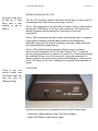
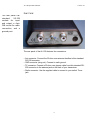
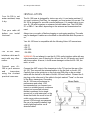
AL-100 Operations Manual
Version 1.0
LDG AL-100
100 Watt Automatic
Tuner for Alinco HF
Transceivers
LDG Electronics
1445 Parran Road
St. Leonard MD 20685-2903 USA
Phone: 410-586-2177
Fax: 410-586-8475
[email protected]
www.ldgelectronics.com
1
AL-100 Operations Manual
Version 1.0
Table of Contents
INTRODUCTION
3
Jumpstart, or “Real Hams Don’t Read Manuals”
3
Specifications
4
Getting to know your AL-100
7
Front Panel
7
Rear Panel
6
INSTALLATION
7
OPERATION
8
Power-Up
8
Basic Tuning Operation
8
Memory Tuning
8
Full Tuning
9
Bypass Mode
9
Status LED
10
Tune Button Press Summary
10
Application Notes
11
A Word About Tuning Etiquette
12
Care and Maintenance
12
Technical Support
12
Two-Year Transferrable Warranty
12
Out of Warranty Service
13
Returning Your Product For Service
13
Product Feedback
14
2
AL-100 Operations Manual
Version 1.0
INTRODUCTION
LDG pioneered the automatic, wide-range switched-L tuner in 1995. From its
laboratories in St. Leonard, Maryland, LDG continues to define the state of
the art in this field with innovative automatic tuners and related products for
every amateur need.
The
AL-100
is
custom made for
Alinco transceivers,
and
uses
your
radio’s TUNE button.
Congratulations on selecting the AL-100 100-watt automatic tuner for the
Alinco HF transceivers. The AL-100 provides semi-automatic antenna tuning
across the entire HF spectrum, at power levels up to 100 watts. It will tune
dipoles, verticals, Yagis, or virtually any coax-fed antenna. It will match an
amazing range of antennas and impedances, far greater than some other
tuners you may have considered, including the built-in tuners on many radios.
The AL-100 is similar to previous LDG tuners, but is specially engineered to
integrate with Alinco HF radios.
The AL-100 connects to the 5-pin tuner port on the back of the radio. The AL100 is powered by the Alinco radio over the tuner interface cable, and tuning
is greatly simplified -- you use the TUNE button on the transceiver to start an
automatic tuning cycle.
You should really
read
the
whole
manual, but this
summary will get
you started.
Jumpstart, or “Real Hams Don’t Read Manuals”
1. Turn off power to your Alinco radio.
2. Connect the HF antenna jack on the transceiver to the “TX” jack on the AL100.
3. Connect your antenna’s 50 ohm coax antenna feedline to the “ANT” jack
on the AL-100.
4. Connect the 4-pin mini-DIN end of the supplied radio interface cable to the
“Radio” jack on the AL-100.
5. Connect the other end of the radio interface cable to the radio’s 5-pin tuner
jack.
6. Turn on the radio and select the desired operating frequency and mode.
7. Consult your radio’s manual on how to activate the external tuner. On most
Alinco HF radios, press FUNC and then TUNE. The transceiver
automatically keys up with a minimal amount of power, and the AL-100
begins a tuning cycle. At the end of the tuning cycle, the original mode and
power level is restored.
8. You’re now ready to operate!
3
AL-100 Operations Manual
Version 1.0
Specifications
Specifications.
Always
operate
within these limits.
• 0.1 to 100 watts SSB and CW peak power, 30W on digital modes.
• Latching relays for ultra low power operation.
• 200 memories for instantaneous frequency and band changing.
• Powered and controlled via radio interface cable.
• Designed specifically for Alinco HF transceivers.
• 1.8 to 54.0 MHz coverage.
• Tunes 4 to 800 ohm loads (16 to 150 on 6M), 16 to 3200 ohms with optional
4:1 Balun.
• For Dipoles, Verticals, Vees, Beams or any Coax Fed Antenna.
• Dimensions: 5.5” W x 6.0” D x 1.2” H.
• Weight: 1 lb
IMPORTANT
SAFETY WARNING
Never install antennas or transmission lines over or near power lines. You
can be seriously injured or killed if any part of the antenna, support or
transmission line touches a power line. Always follow this antenna safety rule:
the distance to the nearest power line should be at least twice the length of
the longest antenna, transmission line or support dimension.
4
AL-100 Operations Manual
Version 1.0
Getting to know your AL-100
You’ll be using your
AL-100 for a long
time; take a few
minutes to get to
know it.
Your AL-100 is a quality, precision instrument that will give you many years of
outstanding service; take a few minutes to get to know it.
The AL-100 is designed for use with Alinco HF radios. Tuning is performed by
pressing the TUNE button on the front of the transceiver. The tuner can be
placed in bypass mode by pressing the Tune button on the tuner
momentarily.
The AL-100 is powered by the radio via the radio interface cable; no separate
power supply is needed. Latching relays hold the tuned configuration
indefinitely, even when DC power is completely removed. Tuning memories
are stored indefinitely in flash memory.
The AL-100 has 200 frequency memories. When tuning on or near a
previously tuned frequency, the AL-100 uses “Memory Tune” to recall the
previous tuning parameters in a fraction of a second. If no memorized settings
are available the tuner runs a full tuning cycle, storing the parameters for
memory recall on subsequent tuning cycles on that frequency. In this manner,
the AL-100 “learns” as you use it, adapting to your bands and frequencies as
it goes.
Front Panel
There is only one
control button and
one status light, but
they do lots of
different things.
On the front panel there is one pushbutton and one LED indicator light.
• Tune button: selects Memory Tune, Full Tune or Bypass
• Status LED: Blinks to indicate tuner status.
5
AL-100 Operations Manual
Version 1.0
Rear Panel
The rear panel has
standard
SO-239
sockets for input
and output, a 4-pin
DIN socket for radio
connection, and a
ground post.
The rear panel of the AL-100 features four connectors:
• Ant connector: Connect the 50-ohm coax antenna feedline to this standard
SO-239 connector.
• GND connector (wing nut): Connect to earth ground.
• TX connector: Connect a 50-ohm coax jumper cable from this standard SO239 connector to the antenna jack on the back of your transceiver.
• Radio connector: Use the supplied cable to connect to your radio’s Tuner
jack.
6
AL-100 Operations Manual
Version 1.0
INSTALLATION
Your AL-100 is not
water resistant; keep
it dry.
Turn your radio off
before you install
the tuner.
The AL-100 tuner is designed for indoor use only; it is not water resistant. If
you use it outdoors (Field Day, for example) you must protect it from rain. The
AL-100 is designed for use with coax-fed antennas. You need a balun to use
your AL-100 with longwires or antennas fed with ladder line. The LDG RBA4:1 or RBA-1:1 are ideal, depending on the antenna and transmission line
used.
Always turn your radio off before plugging or unplugging anything. The radio
may be damaged if cables are connected or disconnected while the power is
on.
Your AL-100 tuner is compatible with the following Alinco HF transceivers:
The
AL-100
radio
interface cable won’t
work with any other
radios.
Connect your AL100 to your antenna
and
transceiver
using the shortest
practical coax runs.
• DX-70
• DX-77
• DX-SR8
DX-SR9
WARNING: Do not attempt to use the AL-100’s radio interface cable with any
other transceivers, even if the plug fits. At best, the AL-100 simply won’t work
with these radios. At worst, it could cause damage to either the AL-100, the
radio, or both.
Connect the ANT output of the transceiver to the TX input on the rear of the
AL-100. Then connect the antenna feedline to the Ant jack on the AL-100.
Carefully line up the guide pin on the 4-pin mini-DIN plug on the provided
cable with the socket on the back of the AL-100 and connect. Connect the 5pin plug on the other end of the cable to the jack marked “Tuner” on the rear
of the Alinco transceiver. Grounding
the AL-100 tuner will enhance its
performance and safety. LDG
recommends that you connect your
tuner to a suitable ground; a common
ground rod connected to buried
radials is preferred, but a single
ground rod, a cold water pipe, or the
screw that holds the cover on an AC
outlet can provide a serviceable
ground. LDG strongly recommends
the use of a properly installed, high
quality lightning arrestor on all
antenna cables.
7
AL-100 Operations Manual
Version 1.0
OPERATION
Your
AL-100
is
powered by your
radio.
You can let your AL100
handle
tuning
automatically, or you
can start a tuning
cycle
manually
if
needed.
Your AL-100 saves
tuning
parameters
so it can tune
instantly when you
return
to
that
frequency.
Power-Up
Turn on the transceiver. The LED on the front panel of the AL-100 will blink
once. If it doesn’t, turn off the radio and recheck your connections.
Basic Tuning Operation
Tuning operation is controlled by the FUNC/TUNE buttons on your Alinco
transceiver. The radio will transmit a carrier and the tuner will perform an
automatic tuning cycle. You can also control your tuner from its front panel
using the Tune button1.
There are two types of tuning cycle: memory tuning and full tuning. Memory
tuning restores tuning parameters stored after a previous successful tune on
or near the present frequency. Memory tuning is the default mode.
A full tuning cycle “starts from scratch”, usually on a new frequency, and
begins a tuning sequence in which the AL-100 rapidly tries various
combinations of inductance and capacitance to find the best match possible.
If an acceptable match is found (SWR < 1.7), the settings are saved in a
memory associated with the current frequency so that they may be quickly
recalled in the future via a memory tuning cycle. In this manner, the AL-100
“learns” your preferences; the longer you use it, the more closely it adapts
itself to your favorite bands, frequencies and antenna characteristics.
You will probably use memory tuning most of the time; it takes advantage of
any saved tuning settings, but automatically reverts to a full tuning cycle if no
stored data is available. At the end of a tuning cycle the carrier is held for one
second so that you can read the final SWR on the transceiver’s internal SWR
meter or another inline SWR meter between the radio and tuner. The Status
LED will also indicate the status of the tuning cycle.
Memory Tuning
Memory tuning is
the default mode;
you’ll probably use it
most of the time.
To start an automatic tuning cycle press FUNC/TUNE on your Alinco
transceiver as described in your Alinco radio manual. The AL-100 will cause
the transceiver to transmit a carrier for the duration of the tuning cycle, and
the Status LED on the AL-100 will light while tuning. The AL-100 will perform
1
For DX-70 and DX-77 the radio must be in AM or FM mode. The DX-SR8 does not work with the tune button
on the tuner.
8
AL-100 Operations Manual
Version 1.0
a memory tuning cycle if data from a previous tune on the present frequency
is available. Otherwise, it will perform a full tuning cycle, storing the tuning
parameters for future memory tunes. When tuning is complete, the
transceiver will return to receive mode. The Status LED on the AL-100 will
blink to indicate the status of the match (see table below for blink codes).
Watch the transceiver’s built-in SWR meter or use an inline SWR meter
between the radio and the tuner for a more precise SWR reading.
To start a memory tune from the tuner’s front panel, transmit a carrier (AM,
FM, or CW) and press the Tune button until the Status LED lights. Release
the Tune button, but keep the radio keyed, and wait for the memory tuning
cycle to end.
Full Tuning
You can force a full
tuning
cycle
if
needed by pressing
and
holding
the
Tune button.
In some cases you may want to perform a full tuning cycle even when
memory parameters are available. For example, you may have moved the
antenna, slightly changing its characteristics. You can force a full tuning cycle
that will cause the AL-100 to seek a better match than the one already stored
in memory for this frequency.
To start a full tune from the tuner’s front panel, transmit and hold a carrier
(AM, FM, CW) then press the Tune button and hold the Tune button for more
than 3 seconds, until the Status LED lights and then goes out, then release.
Keep the radio keyed for the full tuning cycle to end.
Bypass Mode
Press
the
Tune
button momentarily
to toggle between
active and bypass
modes.
You may place the tuner in “bypass” mode, connecting the transmitter directly
to the antenna; no matching will be performed. To toggle between bypassed
and active mode, press the front panel Tune button on the AL-100
momentarily (0-1 sec) and release. The Status LED will flash three times to
indicate that the tuner is in bypass mode. Press the front panel Tune button
momentarily again to recall the previous tuner settings. The Status LED will
flash once to indicate that the tuner is no longer bypassed. This function is
useful when you wish to compare antenna performance with and without the
benefit of the tuner’s matching network.
9
AL-100 Operations Manual
Version 1.0
Status LED
The
Status
LED
displays
many
different kinds of
information.
The Status LED is used to indicate various operating modes, tuning status,
and error conditions. The followings table lists the LED status codes and their
meaning.
Status LED Indication
Meaning
On Steady When Tuning
Tuning In Process
Blinks 1 Time After Tune
Good Match Found <1.7
Blinks 2 Times After Tune
Medium Match Found >1.7 And <3.0
Blinks 3 Times After Tune
No Match Found
Blinks 4 Times After Tune
No RF Present For Tuning
Blinks 5 Times After Tune
RF Lost During Tune
Blinks 3 Times
Tuner Set To Bypass
Blinks 1 Time
Tuner Set To Previous Match
Tune Button Press Summary
The Tune button has
three
functions,
depending on how
long you hold it
down.
The tuner’s Tune button has three functions, depending on length of press:
• Bypass toggle: short press (0 - 1 second)
• Memory tune: medium press (1 - 3 seconds) LED will come on
• Full tune (disregards memory): long press (more than 3 seconds) LED will
come on for three seconds, then go off.
10
AL-100 Operations Manual
Version 1.0
Application Notes
Here
are
some
helpful notes on
using your AL-100.
Base Station Operation
Install your AL-100 in a convenient spot near your operating position. Connect
to your Alinco transceiver using the cable provided. Connect the tuner to the
antenna connecter of the transceiver using the shortest practical coax cable,
and connect the antenna to the tuner’s Antenna connector. LDG recommends
a properly rated and installed lightning arrestor in the antenna lead, and a
ground wire from the ground post on the AL-100 rear panel to a suitable earth
ground.
Mobile Operation
The AL-100 is perfectly suited to mobile operation. It can be installed under
the dashboard along with the transceiver, or mounted remotely. The only
requirement is that the tuner remain dry. Performance will be enhanced if the
AL-100 is well grounded to the car’s body and frame.
MARS/CAP Coverage
The AL-100 provides continuous tuning coverage over its specified range, not
just in the ham bands. This makes it useful for MARS or CAP operation, or
any other legal HF operation.
You can program
the MF key on the
DX-SR8T to perform
the
FUNC/TUNE
function.
DX-SR8T “MF” Key Shortcut Setup
The Alinco DX-SR8T has an option to simplify tuning. Rather than having to
press FUNC and then TUNE each time a tune is needed, the DX-SR8T radio
allows programming the MF key to perform the same operation as FUNC/
TUNE with a single button press. In order to program the MF key to begin a
tune, connect the radio to a suitable antenna or dummy load. Then, with the
DX-SR8 turned on, perform the following:
•
•
•
•
•
•
Press the FUNC button on the DX-SR8T
Press the MF key
Press the FUNC key again
Press the TUNE (decimal point) key
Wait for the tuning cycle to end
Press the MF key again
Now you can simply press the MF key on the DX-SR8T to begin tuning.
11
AL-100 Operations Manual
Version 1.0
A Word About Tuning Etiquette
Don’t be a Lid! Be
careful
not
to
interfere with other
stations when you
tune.
Be sure to use a vacant frequency when tuning. With today’s crowded ham
bands, this is often difficult. However, causing interference to other hams
should be avoided as much as possible. The AL-100’s very short tuning cycle
minimizes the impact of tuning transmissions.
Care and Maintenance
The AL-100 tuner is essentially maintenance-free. You should always strictly
observe the power limits specified in this manual. The outer case may be
cleaned as needed with a soft cloth slightly dampened with household
cleaning solution. As with any modern electronic device, the AL-100 can be
damaged by temperature extremes, water, impact, or static discharge. LDG
strongly recommends the use of a good quality, properly installed lightning
arrestor in the antenna lead.
Email if you have
questions or need
help.
Your
two-year
warranty
is
transferable if you
sell or give your
tuner to someone
else.
Technical Support
The LDG customer support staff is ready to answer your product question by
e-mail [email protected]). You can also check the FAQ section of
our web page. LDG also keeps on-line product information up to date on our
web site, including product manuals, just in case you lose this one! When you
are thinking about the purchase of other LDG products our website also has
complete product specifications and photographs you can use to help make
your purchase decision. Don’t forget the links to all of the quality LDG Dealers
also ready to help you make that purchase decision.
Two-Year Transferrable Warranty
Your product is warranted against manufacturer defects in parts and labor for
two full years from the date of purchase. This two-year warranty is also
transferrable. When you sell or give away your LDG product, give the new
owner a copy of the original sales receipt and the two-year warranty goes with
the new owner. There is no need to complete a warranty card or to register an
LDG product. Your product receipt establishes eligibility for warranty service,
so be sure to save your receipt. Send a copy of the receipt with the product
whenever you send your product to LDG for warranty repair. Products sent to
LDG without a receipt are considered requests for out-of-warranty repair.
LDG does not warranty against product damage or abuse. This means that a
12
AL-100 Operations Manual
Version 1.0
product failure, as determined by LDG, to be caused by the customer or by
other natural calamity (e.g. lightning) is not covered under the two-year
warranty. Damage can be caused by failure to observe the product’s
published limitations and specifications, or by not following good Amateur
practice.
Out of Warranty Service
We’ll be happy to fix
your tuner even if
it’s out of warranty.
Pack it carefully,
include your receipt
for warranty service,
and ship it to us; no
RMA is required.
If a product fails after the warranty period, LDG wants to help you get it fixed.
Send the product to us for repair any time you like. We will determine what
needs to be done and based on your instructions, either contact you with an
estimate or fix it and contact you with a request to pay any repair charges.
Please contact LDG if you have any questions before you send us an out ofwarranty product for repair.
Returning Your Product For Service
Returning a product to LDG is easy. We do not require a return merchandise
authorization, and there is no need to contact LDG to return your product.
Visit the LDG web site and download the LDG Product Repair Form. On the
Repair Form tell the LDG technicians exactly what happened or didn’t happen
and why you believe the product needs servicing. The technician attempts to
duplicate the problem(s) you had based on how well you describe it so take
the time to be accurate and complete. Ask your shipper for a tracking number
or a delivery verification receipt. This way you know the product arrived safely
at LDG. Be sure to give us your email address so our shipper can alert you
online when your product is en-route back to you. Please be assured that our
staff makes every effort to complete repairs ahead of our published wait time.
We patience appreciate your patience; repairs can take six to eight weeks,
but are often faster. The most recent information on returning products for
service is found on the LDG website under Support, then Tech Support.
Send your carefully packaged unit with the Repair Form to:
LDG Electronics, Inc.
Attn: Repair Department
1445 Parran Rd
St. Leonard, MD 20685
13
AL-100 Operations Manual
Version 1.0
Product Feedback
Keep those cards,
letters and emails
coming; we love to
hear
from
our
customers.
We encourage product feedback! Tell us what you think of your LDG product.
In a card, letter, or email (preferred) tell us how you used the product, how
well it worked in your application, and any suggestions you have for
enhancements or new products. Send along a photo or even a schematic or
drawing to illustrate your narrative. We like to share your comments with our
staff, our dealers, and even other customers at the LDG website:
http://www.ldgelectronics.com/
14