1
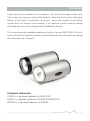
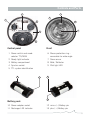
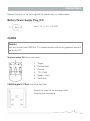
silver SEAFLASH 100 d i g i ta l Canon / Nikon Manual Overview Thank you for your confidence in our products. This manual has been written carefully to help you enjoy your high quality products. Read these instructions thoroughly before use and keep it handy when using them. Take a few moments to familiarize yourself with the functions and handling. If you read the manual carefully nothing shall keep you away from taking excellent underwater pictures. This manual provides complete operating instructions for your SEAFLASH 100digital and can be found in electronic format on the CD enclosed. For information on viewing the instructions see “manuals“. Trademark Information CANON is a registered trademark of CANON INC. NIKON is a registered trademark of NIKON CORPORATION. SEACAM is a registered trademark of SEACAM. 1 Contents Warnings 3 Controls and Parts 4 Compatible Cameras 5 General Description 6 Battery Pack Management 1. General 2. Battery Recharge 3. Battery Maintenance 7 Shooting Modes 1. e-TTL, i-TTL, film-TTL 2. Manual 3. Slave 4. Dual Flash Operation 5. 2nd Curtain Flash Operation 11 Pilot Light 15 S.O.S. Safety Mode 16 Display Error Codes 16 Maintenance 17 Accessories 1. Standard accessories 2. Accessories System 3. Flasharm System 18 Connections 24 Technical Details 28 Environmental Information 29 Warranty 30 General 31 2 Sicherheitshinweise Never try to open the unit – the internal high voltage is potentially lethal. The unit may be serviced only by authorised service centres. Shooting a flash close to eyes can seriously injure them. Use only the original power adapter and TTL cable which are delivered with the flash. Never connect two flashes together to a digital camera in a different way than the one recommended in this manual. Not strictly following the correct connections can result in a damage of the strobes and the camera. Never connect the flash to a camera that is different from the type listed in this manual. Before using the flash with a camera not listed in this manual contact SEACAM. Never connect a power adapter or battery charger to the synchro connector. Do not remove the accu pack from the battery container if the unit is still switched on! Never use this flash together with a different flash brand. Enquire first about its compatibility and special connections. Not following this can result a damage of the unit or the camera. Never shoot the flash directly into the lens of a digital camera. It can damage the camera picture sensor. Use the flash always following the directions of this user manual. Not paying attention to the recommendations of this user manual can cause damage to this unit or to the used camera. Never exceed the maximal depth rate. It will cause the structural damage of the unit. 3 General Description The SEAFLASH 100digital is fully controlled by a micro processor. Some of the significant advantages of using a micro controller are the possibility of managing digital communication on a serial bus with a digital camera and the possibility of easily updating the firmware in order to guarantee compatibilities with future generation digital picture cameras (if possible). In order to improve battery life and to make the battery management very fast, easy and safe for the user a lot of attention was given to the battery pack electronics. This user manual contains important information. By reading it carefully you will learn about the many advantageous features of the flash which will help you take great pictures. CANON or NIKON type On the back plate of the flash, a white or black segment is visible in the middle. By the colour of this segment you can understand if the unit is prepared for CANON or NIKON systems. A white line is for CANON, A black one is for NIKON. 4 Controls and Parts 5 7 6 1 4 8 9 2 3 Control panel Front 1 Power switch and mode selector TTL/MAN 2 Ready light indicator 3 Battery compartment 4 Synchro socket 5 TTL system identification 6 Macro protection ring – removable for wide angle 7 Slave sensor 8 Bulb / Reflector 9 Pilot light LED 11 Battery pack 10 Power adapter socket 11 Recharger LED indicator 10 12 13 12 minus (–) Battery pin 13 plus (+) Battery pin 5 Compatible Cameras The SEAFLASH 100digital is suitable for CANON or NIKON cameras. It is compatible with digital / film cameras in e-TTL, i-TTL, film -TTL and in manual mode. CANON The SEAFLASH 100digital is compatible with CANON digital / film cameras in e-TTL, film-TTL and in manual mode. By using digital cameras all the special functions as, +/– flash compensation, automatic AF light, pre exposure lamps, automatic standby, etc. are supported. NIKON The SEAFLASH 100digital is compatible with NIKON digital / film cameras in i-TTL, film-TTL and in manual mode. By using digital cameras all the special functions as, +/– flash compensation, automatic AF light, pre exposure lamps, automatic standby, etc. are supported. 6 Battery Pack Management The SEACAM removable NiMH battery pack is located under the battery container cap (3). Open – unlock the cap by turning the knob from the “lock” to the to the “open” position and pull it out. When a battery pack is inserted the cap will pop out by itself. Close – turn the knob to the ”open” position. Now hook the small latch at the cap into the back plate, press it down and turn the knob from the “open” to the to the “lock” position. Information Maintain / check the o-ring when opening and grease the sealing surface regularly. Close the battery container cap always completely to avoid forgetting it in stressful situations! ATTENTION! Never charge the battery back inside the battery container! Always prevent water or moisture from entering into the battery container or into the batteries. Close the battery container (3) before using the flash underwater. If no synchro cable is connected, close also the synchro socket (4) with the protection cap. Feature The battery container is completely sealed. In case water enters due to an incorrect battery cup positioning or an o-ring failure, the electronic will not be flooded. Only battery pack and battery contacts can be damaged and will have to be replaced. 7 Battery Pack Management The battery pack is made of selected high current capable NiMH batteries. It is equipped with a built-in electronic circuit to make battery management easy, fast and safe. The battery fits only in one position into the battery container. To charge the battery pack pull up the metal ring and remove it from the container. ATTENTION! Do not remove the accu pack from the battery container if the unit is still switched on! During normal use the flash micro processor checks the battery status permanently and advises the user by beeping when it‘s close to being completely discharged. The flash stops and automatically switches off when the battery is fully discharged in order not to damage it. 1. General A fully recharged battery pack can achieve approx. 250 lamps at max power. When the battery is low, the ready flash indicator start to blink every minute for 4 seconds and an audible alarm is emitted. When the battery is completely discharged a continuous alarm is emitted. After 30 seconds the unit automatically shuts off in order not to damage the battery. If the flash is completely discharged and you try to switch it on again, the flash can start a series of on / off cycles without switching it on completely. Simply remove the battery pack and recharge the battery. Do not leave the battery inside the flash when flash is not in use in order to avoid a slow and thorough battery discharge. 8 Battery Pack Management 2. Battery Recharge Prior to the first use the battery must be fully charged before disconnecting it from the power supply. The battery can be recharged also if it is not fully discharged. ATTENTION! For charging the battery pack has to be removed from the battery container! After connecting the power adapter to the power adapter socket (10), the charge process starts and the control LED (11) starts to blink. When the charging cycle ends the control LED (11) is permanently lit and the battery enters into trickle charge. It can now be disconnected from the power supply (not necessary). It takes approximately 3 hours for the empty battery pack to fully charge. If an error is detected by the microprocessor, the charging process is stopped immediately and the control LED (11) starts to blink at a high frequency. In this case disconnect the power adapter, wait for the battery to cool down. If the control LED (11) recommences blinking at a high frequency the battery might be defective and must be serviced or replaced. IMPORTANT! For all new NiMH batteries or for battery packs stored for a long time, a few full charge / discharge cycles (3 – 4) are necessary to refresh the batteries for perfect conditions. A car / boat power adapter 12 – 14 V is available as an accessory. 9 Battery Pack Management 3. Battery Maintenance As for all NiMH battery it‘s advised to fully discharge the battery when possible before recharging. To discharge the battery, leave it inside the flash and switch it on, turning on the pilot lamp. The flash will automatically shut off when the battery is empty. If battery performance is low, it will increase after a few full discharge/recharge cycles. If the battery pack is left inactive for a short period of time it can be fully recharged and will reach its maximum energy level. IMPORTANT! To avoid batteries overcharge never try to recharge a fully charged battery pack! ATTENTION! Never perform a series of full power shoots to discharge batteries. This will decrease flash lamp life and can also result in a flash damage. Never short circuit any battery terminals – it will damage the battery pack! 10 Shooting Modes Three different shooting modes are available, they are selectable with the main knob (1): TTL, Manual, Slave. 1. e-TTL, i-TTL, film-TTL The energy delivered by the flash is calculated by the camera to obtain the correct exposure. Set the main know (1) to ON/TTL. When the flash delivers a full power lamp the user is advised of the possible underexposure by an audible beep and blinking of the ready LED. 2. Manual Mode The user can choose the flash energy between 5 different steps. Information With digital cameras no pre lamp is emitted. 3. Slave Mode In slave mode the flash is triggered by the slave sensor (7) placed inside the reflector without a synchro cable. This sensor is very sensitive and allows working with a certain distance between the main flash and the slave flash. To enter slave mode, turn the main switch (1) to SLAVE position and then back again one step within two seconds. The ready LED (2) will change colour from red to yellow to indicate the Slave mode. Then select the power required between the available levels. 11 Shooting Modes ATTENTION! In slave mode no TTL is available. If a digital camera is connected to the synchro socket, the Slave mode is auto matically inhabited and the light sensor (7) will not work. 4. Duale Flash Operation There are different ways of operating two strobes with a digital camera. It is very important to note the information below to achieve perfect functionality without damaging your camera. Please read the following information very carefully! Important – for CANON users! e-TTL use with CANON cameras requires S6 sockets on the flash and the camera. (with all the six wires connected to both strobes). Set both units to TTL mode. When the unit is connected to the camera, it automatically detects the camera transmission protocol. This is an easy method of using two flash devices in e-TTL or in manual mode. If you want to shoot only one flash, just switch off the unused flash device. Important – for NIKON users! For i-TTL use with NIKON cameras S6 sockets on the flash and the camera are recommended. Connect the main flash (master) always to the left socket – the second flash (slave) to the right socket. 12 Shooting Modes Feature If two strobes are used you have to use the dedicated SEACAM-NIKON digital dual strobe connector (S-N DDSC). This circuit has to be placed inside the camera housing and needs an S6 socket as the master. To be more flexible SEACAM always recommends two S6 sockets. ATTENTION! Use only SEAFLASH 100D in dual TTL flash mode! When using two flash devices, the master controls the slave. The master is directly connected to the camera (with all six wires connected to the camera). It calculates the required energy for the correct exposure and transmits the information by the TTL cable to the slave. The master can operate in TTL (A) or MAN mode, while the slave should always be left in the TTL (A) mode. If different energy levels are required from the two strobes, in i-TTL mode, the user has to adjust the distance of the two flashes from the subject to achieve the desired effect. In manual mode the user can switch both flash devices to MAN and then manually select the desired energy level steps. Feature When setting the slave to TTL (A) the slave always follows the main strobe in manual mode. If you need different manual settings you have to adjust the devices separately. 13 Shooting Modes IMPORTANT! SEACAM suggests using two SEAFLASH 100digital only with the S-N DDSC circuit installed. This system has been fully tested and has been proven to work well. Using different flashes from the ones suggested can result in a damage of the camera and flash devices. Before connecting different flash brands enquire about their compatibility. 5. 2nd Curtain Flash Operation The SEAFLASH 100D electronic is prepared to use the 2nd curtain flash. NIKON – This function is working in any mode. CANON – To activate this mode you have to set the Slave Mode with the main power switch (1). ATTENTION! On rare occasions during normal use the digital camera can lose the communication with the flash. If this happens, switch the camera and the flash off and on again in order to reset the communication between the units. If the problem occurs repeatedly check and clean the camera hot shoe, the strobe connectors and wires. Wires plugs and sockets must be absolutely dry to be working flawlessly. Water inside the connectors can stop the data transmission and TTL working mode. 14 Pilot Light A 3 W power LED (9) generates a very bright pilot light. This light beam of 10° allows an easy and perfect setting of the flash. The Power LED has an output of about 180 lm, equal to a 10 W halogen bulb. The pilot light is switched on and off with the main switch (1). Because of the dual function of the knob there is a trick to switch it on and off. Turn the main knob from the ON position one step forward and back within 2 seconds it will switch on the pilot light. Repeating this switching you can turn off the pilot light again. Feature When the flash is connected to a digital camera the automatic pilot light feature is available. The pilot light turns on automatically when the camera auto focus system needs more light to work. During flashing the pilot light is switched off automatically. With CANON digital camera you have to set the AF selector to S and select the single shooting mode. With NIKON digital camera you have to set the to AF selector to S or M. No automatic function in C. IMPORTANT! The automatic auto focus assisting light will work only if the AF-illumination is activated in your camera menu. If you don’t like this function deactivate it. 15 S.O.S. Safety Mode For security reasons, to call attention your flash is equipped with a true S.O.S. function. With the power switch (1) in the SOS position a true S.O.S. light signal is generated. This feature can also be used to test the flash. ATTENTION! Use the S.O.S. signal only when really needed and never use it to discharge the battery. Display Error Codes If an error is recognized by the flash micro processor, like an internal too high temperature, or an internal malfunction, an audible alarm is emitted and all the activities of the flash are stopped. Turn off the unit, allow the unit to cool down before switching it on again. If an error state is always active, the unit will need to be serviced. ATTENTION! Never leave the flash unprotected in the sun or a hot place! 16 Maintenance Rinse your flash using fresh water after every dive in the sea and dry it carefully. Clean with a mild cleaner and lubricate the threads regularly. S6 and N5 sockets require particular care and attention. Make sure that the contacts are given regular inspection that the plugs are clean and o-rings slightly lubricated. S6 socket The S6 plug is a very safe and sturdy plug in system. Its contact system is very precise and secure, combined with a 4 time o-ring sealing system which is easy to maintain. Plug in – tighten the nut – ready to go! N5 socket Pay attention when plugging it in; hold it at the anti-kink sleeve of the spiral cord, completely pull the movable nut back and tenderly press the plug in as soon as tongue and groove click into place. Then tighten the nut. ATTENTION! If no TTL cable is connected, close the synchro socket (4) with the protection cap. IMPORTANT! Keep all connections dry. Apply our contact oil regularly, which reduces corrosion and increases lifetime enormous. Grease o-rings as usual! 17 Accessories 1. Standard Accessories The flash is supplied with following accessories as standard: • Exchangeable battery pack • Power supply Input: 100 – 240 V, ~ 1.5 A, 50/60 Hz Output: 12 – 14 V, 1.5 A • Macro protection ring, removable for wide angle shots • Synchro cable • Protection cap for synchro socket • Spare parts and maintenance set • Neoprene bag for the accu pack • User manual 2. Accessories System Optional accessories available: • DIFFUSOR To get softer light from your strobe – mount the diffusor instead of the macro protection ring. • MACRO FILTER For shooting shy animals – these filters are reducing the bright ness of your pilot light – available in red and frost. • SNOOT To shape the light of your strobe you can mount the 3-part extendable snoot. You are able to get 3 different spots of light. • SWITCH EXTENSION Extending the control switch for an easy use in cold water. • NEOPRENE COVER Protecting your entire flash. • NEOPRENE DOME COVER Front dome protection. • CAR-/BOAT POWER ADAPTER 12 – 14 V For mobile charging. 18 Accessories Diffusor Macro filter Snoot Switch extension Neoprene cover Neoprene dome cover 19 Accessories 3. Flash Arm System Introduction We have made your flash arm system for many different uses. With its patented brake disc technology, the retention force is easily sufficient to hold heavy strobes in position, even out of the water. The flash arm offers the ability to be sensitively and quickly adjusted underwater. The hollow, tubular design gives extra buoyancy and different arm lengths improve the swivelling range for both wide angle and macro considerably. There is an infinite variety of positions possible. Function The system is made of a brake disc technology. A brake surface on two fibreglass holders fixes the aluminium ball continuously variable. The ability to a sensitively adjustment underwater is done by special fixation levers. Depending the type of flash arm different extension arms are connected together by joints. 20 Accessories Fixation Use the M8 stainless steel insert thread at the bottom of the flash to fix the SEAFLASH 100digital on the flash arm. The M8 ball adapter is the best way to connect it to our reliable flash arm system (optional). Clean the thread regularly and grease slightly. Mounting Using the flash arm base you fix the system to your housing. Tighten this part carefully with the fixation screw at the housing T-pieces. The best and quickest system to mount your arm is with released joints. Afterwards adjust the flash system to your working position and fix it you like by tightening the fixation levers. Feature If your fixation levers stop at a particular position, you easily can adjust them by pulling out changing the position and pushing back. 21 Accessories How to Use Take always care on a secure fixed flash arm system, if you enter / leave the water. Keep attention on bumping housing and flash by a badly fixed arm system. Arriving the water, trim your system to the retention force which is needed. In the case of current extend this force to avoid a wrong placement of your flash. Telescope Extension This extension enables you to enlarge the arm length various. By turning the pipes you are able to adjust as you like. This system is not constructed for an underwater extension, because the position of the flash is turning. It is best to save keeping different arm length when travelling. If sand or mud enters the pipes, you can easily clean it by removing the plastic screw and open the extension. Maintenance Rinse your flash arm system carefully after every dive with fresh water and turn the joints. Clean the aluminium balls regularly with a scotch bright sponge and the brake surface with acetone, alcohol or thinner. Grease the screws and fixation levers. You can dismount the levers with a screwdriver and clean them also inside. Store the complete flash arm in the practical neoprene bag. Information To avoid adhere of the brake surface after use don’t store wet joints tightened! ATTENTION! Grease on the brake surface reduces the retention force enormous! 22 Accessories Standard flash arm Telescope arm Stabile joint Cleaning of joints Synchro cable S6 plug 23 Accessories Flash Arm Combinations 24 Standard combination 1 Standard combination 2 Makro combination 1 Makro combination 2 Close up combination Wide angle combination Connections Connect the flash to the housing and the camera only as shown below. Battery Power Supply Plug (10) Input: 12 – 14 V, 1.5 A DC CANON Feature You can connect two CANON e-TTL strobes parallel without any problems and will get dual e-TTL. Synchro socket S6 (wires rear view) 1 2 3 4 5 6 Trigger Camera data Ground TTL / Clock Ready / Clock Flash data CANON digital 1/2 flash (hot shoe top view) Connect all wires to the housing socket following the numbering. 25 Connections NIKON ATTENTION! Never connect two flash devices parallel to a digital NIKON camera. It can result in serious damage of flash and camera. Synchro socket N5 (wires rear view) 1 2 3 4 5 Trigger TTL / Data Ground Acknowledge Ready / Clock Synchro socket S6 (wires rear view) 26 1 2 3 4 5 6 Trigger TTL / Data Ground Acknowledge Ready / Clock Slave flash output Connections NIKON digital / film 1 flash (hot shoe top view) Connect all wires to the housing socket following the numbering. NIKON film 2 flash (hot shoe top view) 27 Connections NIKON digital 2 flash (hot shoe top view) no digital dual strobe connector (S-N DDSC) installed NIKON digital 2 flash (connection on component side) with digital dual strobe connector (S-N DDSC) installed Connect all wires to the housing socket and to the camera hot shoe following the numbering. J1 Main strobe (master) J2 Second strobe (slave) J3 Camera (hot shoe) 28 Technical Details • CANON digital e-TTL / film-TTL • NIKON digital i-TTL / film-TTL • Energy 100 Ws • UW guide number 10 – ISO 100 / 1 m at full power • Coverage light angle 130° • 250 flashes at full power • Recycle time 0.1 – 2 sec • Manual light level selection in 5 different steps • Color temperature 4400 °K • 10° Power LED, 110 lm in manual and automatic mode, continuous burn time 3 h • Slave sensor, high intensive for all manual settings • True S.O.S. safety signal for approx. 6 h • Synchro socket S6 or N5 • Automatic charger, integrated in the accu pack, fully controlled by –ΔU, temperature and time, charging time 180 min • High quality, removable NiMH battery pack, NiMH 4.8 V / 3.2 Ah, with integrated charger • M8 HeliCoil insert thread for flasharm connection • Dimension Flash L x Ø: 160 x 90 (85) mm, 990 g, underwater 0 g Akku pack L x Ø: 100 x 45 x 25 mm, 270 g • Depth rating – 80 m / – 240 ft 29 Environmental Information Disposal of Electrical and Electronic Equipment User information for private households According to our company philosophy your product was developed and manufactured using high quality materials and components which can be recycled. The symbol with the crossed-out bin on our products and / or accompanying documents signifies that at the end of their life cycle electrical and electronic products must be disposed of separately from household waste in countries of the EU and EEA (Norway, Iceland and Liechtenstein). The proper disposal of these products helps our environment and prevents potential adverse effects on human health and the environment. We therefore ask that you take these products to your municipal collection point for recycling and resource recovery where the devices can be returned at no cost. Alternatively send these to our main plant for proper disposal. For more detailed information on your nearest collection point please contact your communal government. Information for Business Clients For proper disposal of your electrical and electronic equipment, please contact your dealer or local supplier. They will be able to assist you further. Battery Disposal Batteries and rechargeable batteries do not belong into the household waste! As consumers in EU countries you are obliged to return used batteries and rechargeable batteries. You can return these used batteries to appropriate collection points in your community or anywhere where these particular types of batteries are sold. The batteries are taken back free of charge to the consumer. 30 Warranty A 24 month warranty from the date of invoice for function and tightness applies to the flash delivered. This warranty is valid within the EU member countries – for non EU member countries the warranty of the country to where the article is delivered applies. Warranty repairs do not extend the warranty time. This warranty does not apply in the event of accidental damage, negligence, improper handling, damage to cables, water entering at improperly closed battery container cup or connections, disregarding of operating conditions and operating instructions, as well as unauthorized repairs or changes by a third party. Synchro cables, batteries, flash bulb and consumables parts are not covered by warranty. If the warranty seal is broken the warranty immediately expires. SEACAM shall not be liable for direct or indirect damage to persons and devices or (build in) cameras and reserves the right to make technical changes or replacements. All SEACAM terms you can find on our website: www.seacam.com/en/contact/terms 31 General If you have any question regarding this unit please contact us: SEACAM service C.v.Hötzendorfstrasse 40 8570 Voitsberg · Austria T +43 . 3142 . 228850 F +43 . 3142 . 228854 E service @ seacam.com www.seacam.com © SEACAM, Revision C/N 10.2012 Layout: NO-SUN Marketing & E-Business, www.no-sun.com 32 SEACAM C.v.Hötzendorfstrasse 40 8570 Voitsberg · Austria T +43 . 3142 . 228850 F +43 . 3142 . 228854 E service @ seacam.com www.seacam.com