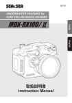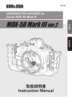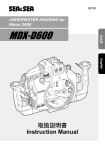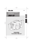
1
06152 UNDERWATER HOUSING for Canon EOS 7D 日本語 MDX-7D English 取扱説明書 Instruction Manual Introduction Thank you for purchasing SEA&SEA products. Please read this instruction manual carefully prior to using this product. Only with a thorough understanding of this manual’s content will you be able to use the housing correctly. After reading the manual, please be sure to keep it in a place where you can easily come back to it at any time. Note: Pressure-resistance inspection sticker Products bearing this sticker are those that have passed SEA&SEA’s criteria-based inspection for pressure resistance. Contents Safety Precautions .................................................................... E-2 Precautions on Handling the O-ring .......................................... E-4 Accessories .............................................................................. E-6 Identification of Parts ................................................................ E-7 Leak sensor ........................................................................ E-8 Finder .................................................................................. E-9 Preparation for Setting Up ...................................................... E-10 Prepare the housing and port ............................................ E-10 Prepare the digital camera ................................................ E-10 Prepare the connecting accessories ................................. E-10 Opening and Closing the Housing .......................................... E-11 Attaching and Detaching the Port ........................................... E-13 Mounting the Camera in the Housing ..................................... E-15 With the sync cord / the YS converter................................ E-15 With the fiber-optic cable ................................................... E-18 Connecting the Strobe ............................................................ E-20 With the sync cord / the YS converter................................ E-20 With the fiber-optic cable.................................................... E-23 External Controls ....................................................................E-24 Attaching the Optional Accessories ........................................E-27 Maintenance and Storage .......................................................E-28 Specifications ..........................................................................E-29 E-1 Safety Precautions For safe handling of the product, please read the following precautions carefully before use. Failure to heed the precautions listed below could result in serious consequences. To prevent injury or damage to yourself and/or others, please observe the precautions as they contain highly important information related to personal and product safety. WARNING Situations that could result in severe injury or death. CAUTION Situations that could result in property damage or personal injury. WARNING Keep out of reach of children to prevent accidental ingestion. If swallowed, seek medical advice immediately. CAUTION Carefully observe the instruction manual for the compatible camera for this product before use. This product must be used in combination with the optional port for SEA&SEA digital SLR camera housings. This product cannot be used alone. This product has been designed and manufactured for use at a water depth within 60m / 200ft. Please note that diving to a depth in excess of 60m / 200ft may cause damage to the product or may lead to water leakage. Unauthorized disassembling and/or modification could result in malfunction or flooding, and void product warranty. Take the product to a SEA&SEA authorized service center for repair or inspection. Should you notice smoke or an unusual smell coming from the product, turn it off and remove the batteries immediately, taking care to avoid burns. Continued operation could result in injury. After removing the battery, take the product to a SEA&SEA authorized service center for inspection. Discontinue use and turn the product off immediately should you notice flooding or leakage. When the product is flooding, interior pressure may build up. Please be careful when opening the product as water may spurt out or the cap may open explosively and cause injuries. The product has been constructed with an airtight seal. When packing the product for airplane travel, do not seal-up the product to alleviate pressure build up due to atmospheric changes. Do not open the product in a wet or sandy environment. Protect the interior from moisture and debris in order to prevent malfunction or flooding. Avoid strong shocks/impacts or excess stress to prevent malfunction, damage or breakdown. Make sure that the product has been securely mounted to other products in order to prevent injury, fall or missing. E-2 Safety Precautions Do not rest heavy weight on the product. It might deform the outer casing, damage internal parts, make the waterproofing fail, or result in fire or electric shock. Please note that some marks may be left on the camera scraping against the dials or gears of the housing. Handle the product carefully so as not to scratch the front port, the lens, the flash window or the finder. Always dry the front port, the lens, the flash window or the finder using a soft cloth to prevent stain or salt residue from marring the glass surface. Rinse the product with fresh water, after underwater use. Ensure that the product is waterproofed before rinsing. Refer to [Maintenance and Storage] (P.E-23) for details. Make sure that the connectors have been secured with the connector caps before rinsing the product with fresh water, after removal from other products. Never use chemicals, cosmetics, any petroleum solvents such as paint thinner, or neutral detergent on the product. They may deform and damage the product. Do not leave the product in places with hot temperatures such as inside of a car or in a car trunk in summer. The heat may deform plastic parts of the product, damaging internal parts and resulting in potential fire or electric shock. If the product is sealed tight in hot conditions, heated air expanding inside the product may deform the casing and ruin the waterproofing. Do not store the product in wet or high humidity place, to avoid mold, rust, corrosion or malfunction. Do not store the product with naphthalene or camphor mothballs, or in locations such as a laboratory where chemicals are used. This environment can cause mold, rust, corrosion or malfunction. SEA&SEA SUNPAK Co., Ltd. assumes no liability for compensation of loss of captured images or expenses caused by loss of images, even if you are unable to shoot due to a product defect or malfunction. SEA&SEA SUNPAK Co., Ltd. will not be responsible for the replacement or compensation for cameras, lenses or those accessories damaged due to your invalid operation. SEA&SEA SUNPAK Co., Ltd. assumes no liability for errors or discrepancies in this manual. Carefully observe the O-ring maintenance manual for the handling of O-rings before use. The silicon grease included in the product package is inedible. E-3 Precautions on Handling the O-ring This product is kept watertight by the O-ring. To keep the O-ring functioning properly, please observe the following. Improper handling of the O-ring could cause flooding. CAUTION SEA&SEA products use blue O-rings. These O-rings are impregnated with silicone oil through a special process. The lubricating effect of the O-ring lasts as long as the silicone oil is gradually seeping out from within. For the maintenance of these blue O-rings, make sure to use genuine SEA&SEA silicone grease (O-ring grease for use with the blue O-rings that comes in tubes with blue lettering and blue caps). If you use silicone grease from other companies or SEA&SEA’s own silicone grease that comes in tubes with black lettering and black caps, the grease you apply will be sucked into the blue O-rings due to their special characteristics, which will result in insufficient grease. If this happens even once, the O-ring will not revert to its normal state and must be replaced. If the grease is insufficient, the O-ring will not slide, and it will become harder to open and close the waterproof parts. Because of this, it could become impossible to open or close the housing or it could cause flooding, so please refrain from using the housing with insufficient grease. Are there any scratches or cracks in the O-ring? Check the O-ring to make sure there are no scratches or cracks. If there are, replace the O-ring with a new one immediately. When handling the O-ring, do not use pointed metal objects, which could damage the O-ring. Use of the included O-ring remover is recommended. O-ring remover Be careful about dust, sand, and hair Check the O-ring to make sure that there is no dust, sand, or hair on the O-ring, in the O-ring’s grooves, or on the O-ring’s contact surfaces. If any of these things are attached, remove them completely. If used as is, these things could cause flooding. E-4 Precautions on Handling the O-ring Coat with silicone grease Silicone grease protects the O-ring from chafing. After checking the O-ring to make sure that there are no scratches, dust, or debris, apply a light coating of silicone grease to the entire O-ring with your finger. Applying too much grease will make it easier for dust and debris to adhere to the O-ring, and could cause flooding. Do not twist the O-ring When fitting the O-ring into the O-ring groove, insert it straight into the groove; do not bend or twist it. Remove the O-ring for inspection before each use In principle, the O-ring should be removed before each use so that the O-ring, O-ring groove, and O-ring contact surfaces can be checked. This is because you cannot find any sand or debris that may have gotten into the O-ring groove if the O-ring is not removed. For routine maintenance prior to each use, it is advisable to make sure to remove the O-ring. Be careful about how you store O-rings When storing spare O-rings or O-rings that you have removed from the housing, keep them in a cool place out of direct sunlight. Also, when storing O-rings, do not place heavy objects on them or twist them. O-rings last for one year Although it depends on how well they are maintained, how often they are used, and how they are stored, O-rings generally last for one year. It is advisable to inspect them before use, and replace them early. E-5 Accessories Before using this model, check to make sure that all accessories are present. MDX-7D O-ring remover Sillicon Grease Attachment tool Hex Wrench Connector cap (x2) (mounted) Fiber-optic cable socket cap (x2) (mounted) CR2032 lithium battery (mounted) Housing body cap (mounted) O-ring Maintenance Manual MDX-7D Instruction Manual (this manual) E-6 Identification of Parts YS converter bulkhead Strobe bulkhead Fiber-optic cable socket Accessory shoe Main command dial Shutter lever Focus / Zoom dial Grip Front case Port lock Locking latch One-touch RAW+JPEG / Direct print button Quick Control button Power switch Mode dial Finder Metering mode selection / White balance selection button AF mode selection / Drive mode selection button ISO speed setting / Flash exposure compensation button Start / Stop button Setting button AE lock / Index / Reduce / AF point selection / Magnify lever AF start button Sub-command dial Menu button Picture Style selection button Info button Playback button Erase button E-7 Live View shooting / Movie shooting switch Multi-controller Rear case Identification of Parts Sync connector Front case Quick shoe Guide pin Quick shoe base Quick lock Guide pin Leak Sensor The leak sensor lights up in red if water leakage is detected while underwater. If the leak sensor lights up, surface as soon as you safely can and remove the camera from the housing. Leak Sensor CAUTION If a lot of water leaks in, the atmospheric pressure inside the housing will increase, which is very dangerous. When releasing the locking latches, the rear case could come flying off, so be very careful. Replacing the leak sensor battery Instructions for replacing the leak sensor battery set in the rear case. CAUTION 1 2 Use CR2032 batteries. Press the round center part firmly and remove the battery Insert the battery with the plus side up E-8 Identification of Parts Finder This product comes equipped with a 0.5x pick-up finder. The finder can be replaced with an optional finder unit so you can change the finder magnification to match your shooting conditions. Replacing the finder 1 Rotate the finder unit mounted on the rear case in a counterclockwise direction to remove it The screw areas are coated in grease, so be careful not to touch them. 2 Rotate the replacement finder unit in a clockwise direction to attach it CAUTION Before attaching the finder, check to make sure that there is no dust, dirt, or debris inside it. When replacing the finder, do not touch the surface of the finder lens. When replacing the finder, always refer to the instruction manual provided. E-9 Preparation for Setting Up This product must be used in combination with the optional equipment (digital camera, port, strobe, accessories etc.) for underwater photography. In order to set up the equipment, prepare each item correctly. Prepare the housing and port Maintaining the O-ring This product is kept watertight by the O-ring. To keep the O-ring functioning properly, please observe the following before setting up. O-ring Make sure to remove the O-ring when maintaining. For detailed O-ring maintenance methods, please see the O-ring maintenance manual. CAUTION Make sure to fit/install the O-ring into the groove properly after maintenance. Prepare the digital camera This product is exclusively designed for use with Canon EOS 7D digital camera. Other cameras are not compatible with this product. Make sure that there is sufficient battery power remaining and the image storage medium has enough room for the number of pictures. Remove the eyecup from the camera. Remove the strap or the LCD monitor cover from the camera, if any of these accessories are attached. If the lens has a focus mode switch, set it properly. Make sure the camera is operating correctly, referring to the camera's instruction manual for details. Prepare the connecting accessories When using external strobes, lights or other accessories in combination with this product, prepare the equipment before setting up. If the accessories are kept watertight by O-rings, make sure the O-rings are properly maintained. If the accessories are powered by batteries, make sure that there is sufficient battery power remaining. Make sure the equipment is operating correctly, referring to the instruction manual provided with the equipment. E-10 Opening and Closing the Housing Opening and closing the housing is done with the locking latches. Here we will explain how to open and close the locking latches. Opening the locking latches 1 With the surface of the rear case facing up, press and hold the right and left locks (①) and remove the locking latches from the hooks (②) CAUTION When removing the locking latches, be sure to use the tips of your fingers, not your fingernails. If you lock the locking latch after it is removed from the hook, it is easier to remove the rear case. E-11 Opening and Closing the Housing パチン錠を閉める Closing the locking latches 1 2 Set the rear case in alignment with the guide pins (right and left) on the front case First, put the right and left locking latches on the hooks (①), and close the locking latches simultaneously (②) CAUTION Before aligning the rear case and front case, make sure there are no specks of dust, scratches, or deformities on the O-ring and the O-ring contact surfaces. Check to make sure that the locking latches are securely locked. E-12 Attaching and Detaching the Port In order to use this product underwater, the optional port for the camera lens must be attached to this product. CAUTION Only the optional ports designed for SEA&SEA digital SLR camera housings can be attached to this product. This product is delivered with a housing body cap attached to the port mount. Make sure to remove the housing body cap when attaching the port. The housing body cap has no watertight capability. When attaching the port to the housing, always refer to the instruction manual provided. 1 2 Pull the port lock on the underside of the quick shoe base toward OPEN until you hear the sound of it clicking into place OPEN LOCK Align the positioning mark on the front case with the OPEN mark on the port, insert the port into the front case, and then rotate the port in a clockwise direction until it stops CAUTION 3 4 Before attaching the port, make sure there are no specks of dust, scratches, or deformities on the O-ring and the O-ring contact surfaces. Port lock pin Make sure that the positioning mark on the front case and the LOCK mark on the port are aligned Push the port lock toward LOCK until you hear the sound of it clicking into place Make sure that the port lock pin is engaged with the notch in the port. E-13 OPEN LOCK Attaching and Detaching the Port Detaching the port 1 2 Set the port lock to the OPEN position Hold the front case firmly and rotate the port in a counterclockwise direction CAUTION Do not attempt to remove the port with the port lock in the LOCK position. Doing so could damage the quick shoe base. If using NX-90PRO ports (with 4-digit part numbers and black bayonets) with this model, it is necessary to modify the port’s bayonet. NX-90PRO ports with 5-digit part numbers and gray bayonets can be used as is. For details, please contact SEA&SEA or a SEA&SEA authorized dealer. E-14 Mounting the Camera in the Housing CAUTION The camera settings differ depending on the connecting method for the external strobe. Make sure to remove the eyecup from the camera. If used with the eyecup in place, it could cause flooding. Remove the strap or the LCD monitor cover from the camera, if any of these accessories are attached. When connecting the strobe with the sync cord (option) / YS converter (option) 1 Rotate the quick lock in the OPEN direction (①), and then remove the quick shoe from the front case (②) Indentation Tripod socket 2 3 Align the guide pin on the quick shoe with the indentation on the camera, and insert the fixing screw into the camera's tripod socket to set the camera Fixing screw Guide pin Using the included attachment tool, fix the quick shoe to the camera’s tripod socket Fixing screw E-15 Attachment tool Mounting the camera in Housing 4 5 Attach the lens to the camera, and then set the focus mode (AF or MF) Remove the sync connector from the connector holder inside the front case, and make sure the quick lock is in the OPEN position Connector holder Sync connector 6 Quick shoe base Quick lock Align the quick shoe with the quick shoe base, and slide the camera fully forward into the front case Move the sync connector clear of the front case. Do not pop up the camera's built-in flash. To make sure that the gear attached to the lens and the gear on the front case do not hit each other, rotate the focus / zoom dial while sliding the camera into place. 7 8 Align the quick lock with the LOCK position to fix the camera in place Insert the sync connector into the camera's accessory shoe CAUTION When inserting or removing the sync connector, be sure to hold the connector part. If you push or pull on the cord part, it could damage the sync connector or cause contact failures. E-16 Mounting the Camera in the Housing 10 Live View function is only activated when Live View Shooting is set to [Enable] using the camera's menu function. Refer to the camera's instruction manual for details. Set the housing's power switch to OFF, and set the Live View shooting/Movie shooting switch so as to uncover the < > icon (switches are on the rear case). Make sure to match the switch settings on the camera and with those on the housing. Those switches cannot be operated if the settings do not match. M Av Tv Camera's settings C3 C2 C1 9 Set the camera's power switch to OFF, and set the Live View shooting/Movie shooting switch to < > B 8 OFF P CA START STOP ON Power switch Live View shooting/ Movie shooting switch Housing (rear case) setting Power switch Live View shooting/ Movie shooting switch Set the rear case in alignment with the guide pins (right and left) on the front 11 Close the locking latches See: “Opening and Closing the Housing” (P.E-11) Make sure that the O-ring is properly fitted in the O-ring groove before setting of the rear case. パチン錠を閉める Removing the camera from the housing 1 2 3 4 5 Open the locking latches Remove the rear case Remove the sync connector from the camera's accessory shoe Set the quick lock to the OPEN position Slide the camera toward you as you remove the front case E-17 Mounting the camera in the Housing When connecting the strobe with the fiber-optic cable (option) 1 2 3 4 5 6 Rotate the quick lock in the OPEN direction (①), and then remove the quick shoe from the front case (②) Align the guide pin on the quick shoe with the indentation on the camera, and insert the fixing screw into the camera's tripod socket to set the camera Indentation Tripod socket Fixing screw Guide pin Using the included attachment tool, fix the quick shoe to the camera’s tripod socket Fixing screw Attachment tool Attach the lens to the camera, and then set the focus mode (AF or MF) Make sure the quick lock is in the OPEN position Pop up the camera’s built-in flash. Align the quick shoe with the quick shoe base, and slide the front case To make sure that the gear attached to the lens and the gear on the front case do not hit each other, rotate the focus / zoom dial while sliding the camera into place. E-18 Mounting the camera in the Housing 9 10 Live View function is only activated when Live View Shooting is set to [Enable] using the camera's menu function. Refer to the camera's instruction manual for details. Set the housing's power switch to OFF, and set the Live View shooting/Movie shooting switch so as to uncover the < > icon (switches are on the rear case). Make sure to match the switch settings on the camera and with those on the housing. Those switches cannot be operated if the settings do not match. Camera's settings M Av Tv Set the camera's power switch to OFF, and set the Live View shooting/Movie shooting switch to < > C3 C2 C1 8 Align the quick lock with the LOCK position to fix the camera in place B 7 OFF P CA START STOP ON Power switch Live View shooting/ Movie shooting switch Housing (rear case) setting Power switch Live View shooting/ Movie shooting switch Set the rear case in alignment with the guide pins (right and left) on the front 11 Close the locking latches See: “Opening and Closing the Housing” (P.E-11) Make sure that the O-ring is properly fitted in the O-ring groove before setting of the rear case. Removing the camera from the housing 1 2 3 4 Open the locking latches Remove the rear case Set the quick lock to the OPEN position Slide the camera toward you as you remove the front case E-19 Connecting the Strobe This product comes equipped with a strobe bulkhead (①) / a YS converter bulkhead (②) and two fiber-optic cable sockets. fiber-optic cable socket ② ① When connecting the strobe with the sync cord (option) / YS converter (option) Connect the strobe with the sync cord (option) or YS converter (option) when the strobe is triggered in conjunction with the camera. CAUTION Make sure never to connect the Strobe sync cord to the bulkhead for YS converter (②). This may damage the pins on the bulkhead connector. Likewise, make sure never to connect the YS converter's connecting cable to the strobe bulkhead (①). This may damage the pins on the bulkhead connector. Carefully observe the instruction manual for the sync cord / YS converter before use. with the sync cord 1 2 3 Remove the housing's bulkhead connector cap Make sure there are no scratches or debris on the O-ring of the sync cord being connected Align the round mark (or the notch on the tip) of the sync cord with the round mark (or the convex part inside) of the strobe bulkhead, and then push it straight in Sync cord Strobe bulkhead E-20 Connecting the Strobe 4 5 Align the B part of the sync cord with the screws of the strobe bulkhead, and then rotate it until it stops A B C Rotate the C part of the sync cord until it stops Tighten it securely. When removing the sync cord, loosen C first, then B, and then pull the sync cord straight out holding onto A. Do not pull on the cord part. CAUTION If not connecting the sync cord, do not remove the connector cap from the strobe connector. Make sure the cap is firmly secured to avoid water leakage due to a loose cap. After the strobe is connected to the housing, make sure to check that the connected strobe functions correctly before underwater use. After use underwater, make sure to prevent water droplets from dripping into the bulkhead connector by wiping moisture away from the bulkhead connector and then turning the housing upside down and extracting the sync cord. In the event that water droplets do drip into the connector, promptly wipe away all moisture. Using incompatible strobes in combination with the YS converter may result in incorrect operation or cause the camera and strobe to malfunction. Do not rotate the A part when connecting/removing the sync cord as doing so may cause malfunction due to a wiring disconnection. E-21 Connecting the Strobe With the YS converter 1 2 Remove the two screws from the grip for your left hand, and then remove the parts (bracket shoe / lanyard hook) Bracket shoe Lanyard hook Grip Fit the YS converter attachment plate in between the grip and the parts you removed, and then fasten it in place with the screws included with the YS converter YS converter Mounting plate 3 Grip Connect the YS converter's connecting cable to the YS converter connector Refer to the instruction manual provided with the YS converter for details. CAUTION YS converter Connecting cable YS converter connector Refer to the instruction manual provided with the strobe and the YS converter for connection of the YS converter to the strobe. Using incompatible strobes in combination with the YS converter may result in incorrect operation or cause the camera and strobe to malfunction. If not connecting the YS converter, do not remove the connector cap from the YS converter connector. Make sure the cap is firmly secured to avoid water leakage due to a loose cap. After the equipment is connected to the housing, make sure to check that the connected strobe and YS converter function correctly before underwater use. E-22 Connecting the Strobe When connecting the strobe with the fiber-optic cable (option) Connect the strobe with the fiber-optic cable (option) when the strobe is triggered by sensing the light from the camera's built-in flash. 1 2 Remove the fiber-optic cable socket caps Fiber-optic cable socket cap Insert the fiber-optic cable's connector into the socket until it stops Do not remove the caps from fiberoptic cable socket not in use to keep light from entering in. CAUTION Before inserting the fiber-optic cable, check to make sure that there are no scratches or dirt on the connector surface. Scratches or dirt may cause the strobe to malfunction. To protect the surface from scratches or dirt, do not remove the caps from the fiber-optic cable sockets when the cable is not inserted. There is no possibility of water leaking from the fiber-optic cable socket even if the fiber-optic cable/cable socket cap is removed underwater. After the strobe is connected to the housing, make sure to check that the connected strobe functions correctly before underwater use. E-23 External Controls Power switch By rotating the knob as shown, you can turn the power ON/OFF and operate the illumination switch. Power switch Focus / Zoom dial When shooting with a focus / zoom gear: Spacer Pull the focus / zoom dial out and rotate it so that the convex part of the dial is set in the deep groove on the spacer. Deep groove When shooting without a focus / Zoom gear Pull the focus / zoom dial out and rotate it so that the convex part of the dial is set in the shallow groove on the spacer. Shallow groove CAUTION The focus / zoom dial cannot be used if there is no gear mounted on the lens. When using a zoom gear, you cannot shoot with manual focus. If you will be shooting autofocus shots with the focus gear mounted on the lens, make sure to use the shallow groove. If you set it to the deep groove, it could damage the lens. E-24 External Controls AE lock / Index / Reduce / AF point selection / Magnify lever To operate the AE lock / Index / Reduce button Push down the lever to operate the AE lock / Index / Reduce button. Lever Camera AE lock button / Index / Reduce button Housing To operate the AF point selection / Magnify button Push up the lever to operate the AF point selection / Magnify button. Lever Camera AF point selection / Magnify button Housing AF start lever Push up the lever to operate the AF start lever. AF start button Camera Housing AF start lever E-25 External Controls Live View shooting/Movie shooting switch Live View shooting Push the switch up to uncover the < > icon. Switch Movie shooting Push the switch down to uncover the < > icon. Switch Other controls Other control parts on the housing correspond to the operation parts of the digital camera. Refer to the camera's instruction manual for details of each function. CAUTION After mounting the camera in the housing, make sure to check that all of the housing's control parts work properly and the camera functions correctly before underwater use. E-26 Attaching the Optional Accessories This product accepts SEA&SEA optional accessories. By using this product in combination with those accessories, you will be able to try various shooting techniques. CAUTION Lenses, strobes and other accessories have different depth rating. Check the depth rating for each before use. Read the instruction manual for each accessory before use. Accessory shoe SEA&SEA strobes / lights can be mounted to the accessory shoe by using optional Mini Shoe Arm (#29511) or Hot Shoe Arm (#29501). CAUTION <Example> The max. weight of an accessory that can be mounted to the accessory shoe is approx. 750g / 26.3oz (equivalent to the weight of SEA&SEA YS-110α strobe). Remove the accessories from the accessory shoe when carrying the housing out of water. E-27 Maintenance and Storage CAUTION Never use chemicals, cosmetics, any petroleum solvents such as paint thinner, or neutral detergent on the product. They may deform and damage the product. After each use in salt water, make sure it’s watertight, then soak it sufficiently in fresh water. Insufficient soaking causes damage by salt to the product. Salty residue may be left on the product where it will crystallize as it evaporates. Crystallized salt is hard to dissolve and difficult to be removed once formed, and it will result in water leakage. After rinsing, dry the product well with a soft dry cloth, then let the product dry in the shade, out of direct sunlight. Do not dry the product by heating (using a hair dryer, for example). Heating can deform and damage the product. If you will not use the product for an extended period of time, store it away from high temperatures, high humidity, direct sunlight, or extreme cold. Do not store the product with naphthalene or camphor mothballs, or in locations such as a laboratory where chemicals are used. This environment can cause mold, rust, corrosion or malfunction. Always remove the camera from the housing after use. Thoroughly wipe off water before opening the housing and avoid any water drops inside the housing. After using the product, maintain the O-rings before storing. Examine the O-rings before and after each dive. We recommend early exchange of the O-rings, at least once a year. Every two years we recommend a complete overhaul of O-rings regardless of the frequency in use, for the best performance of the product. E-28 Specifications Compatible camera Canon 7D Controls Power switch, Shutter lever, Main command dial, Focus / Zoom dial, Mode dial, Metering mode selection / White balance selection button, AF mode selection / Drive mode selection button, ISO speed setting / Flash exposure compensation button, Live View shooting / Movie shooting switch, AE lock / Index / Reduce / AF point selection / Magnify lever, AF start lever, Start / Stop button, Sub-command dial, Setting button, Multi-controller, One-touch RAW+JPEG / Direct print button, Quick Control button, Erase button, Playback button, Info button, Picture Style selection button, Menu button Construction Body: Corrosion-resistant aluminum alloy Grip: Corrosion-resistant die-cast aluminum Depth rating 60 m (200 feet) Dimensions Approx. 341 (W) × 194 (H) × 141 (D) mm (13.7× 7.8 × 5.7 inches) Weight Approx. 2700 g (5.94 lbs.) (housing only) Accessories ・Silicone grease ・O-ring remover ・Attachment tool ・Hex wrench ・O-ring maintenance manual ・Instruction manual (this manual) Mounted accessories to the product : ・Housing body cap ・Fiber-optic cable socket cap (x2) ・Connector cap (x2) ・CR2032 lithium battery (for leak sensor, preinstalled into battery compartment) * The specifications and appearance are subject to change without notice. E-29 シーアンドシー・サンパック株式会社 〒332-0016 埼玉県川口市幸町3-2-20 TEL.048-256-2251 カスタマーサービスセンター TEL.048-255-8512 http://www.seaandsea.co.jp SEA&SEA SUNPAK Co., Ltd. 3-2-20, Saiwai-cho, Kawaguchi-shi, Saitama, Japan 332-0016 TEL. +81-48-256-2251 World Customer Service Center TEL. +81-48-255-8512 http://www.seaandsea.jp 0936-Z-01A (2010年4月現在 / Current as of Apr.2010)