1
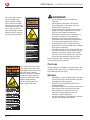
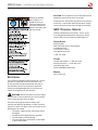
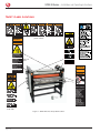
SPIRE III Series Laminator
Models 44T, 64T, 64Ct,
INSTALLATION &
OPERATION MANUAL
Document Number: 1723267 Rev. A
Do not duplicate without written permission from ACCO Brands.
SPIRE III Series – Installation and Operating Instructions
ACCO Brands reserves the right to make changes
to this publication and to the products described in
it without notice. All specifications and information
concerning products are subject to change without
notice. Reference in this publication to information
or products protected by copyright or patent does
not convey any license under the rights of ACCO
Brands or others assumes no liability arising from
infringements of patents or any other rights of third
parties.
Introduction
This publication is copyrighted © 2013 by ACCO
Brands. All rights reserved.
Features
The SPIRE III Series Laminators are designed to
provide you with improved productivity, versatility,
and quality.
Note: Depending on the model of your Laminator
and its version, the photos in this manual may not
look like your Laminator. However, the components
and functions are the same.
•
•
•
•
Simple intuitive control panel with LED
pressure readout
Hand crank for opening and closing rollers
provide infinite choice of settings
Deep Feed Table for feeding larger sheets of
media
2 inch mounting gap for thicker substrates
Applications
•
•
•
•
•
•
•
•
•
Trade show graphics
Posters
Rigid displays
Backlit displays
Window displays
POP displays
Banners
Flexible displays
Directional signage
Films
Cold
•
•
Heat
•
•
•
ACCO Brands
4 Corporate Drive
Lake Zurich, IL 60047
In USA call 800.772.9281
www.gbcconnect.com
Page i
ACCO Brands Canada Inc.
7381 Bramalea Road
Mississauga ON L5S1C4
800.263.1063
www.gbccanada.com
ACCO Mexicana
Neptuno 43, Fraccionamiento Nueva Industrial Vallejo
México 07700 D.F.
Delagación Gustavo A. Madero
(55) 15 00-57 00
www.gbc.com.mx
Arctic® Pressure Sensitive Films
Arctic Pressure Sensitive Mounting Adhesives
Octiva® Thermal Films
Octiva Lo-Melt® Thermal Films
AccuShield®
© 2013 ACCO Brands. All rights reserved. ACCO® is a registered trademark of
ACCO Brands. GBC® is a registered trademark of General Binding Corporation.
1723267 Rev. A
2013/12
SPIRE III Series – Installation and Operating Instructions
Table of Contents
Introduction.................................................................. i
Features................................................................... i
Applications............................................................. i
Films......................................................................... i
1. Safety
Cautions...................................................................1-2
General.....................................................................1-2
Electrical.................................................................. 1-3
GBC Technical Service........................................... 1-3
Safety Label Locations........................................... 1-4
2. Warranty
Limited 90-Day Warranty.........................................2-1
3. Specifications
FCC Class A Notice................................................ 3-2
Canada Class A Notice - Avis Canada, Classe A... 3-2
Modifications........................................................... 3-2
4. Installation
GBC Technical Service........................................... 4-1
Prior to Installation.................................................. 4-1
Installation............................................................... 4-1
Location.............................................................. 4-2
5. Feature Guide
Emergency Stop Switches...................................... 5-2
AUTOGRIP and Multi Core Shafts.......................... 5-2
A. Upper Front Rewind Shaft.................................. 5-2
B. Upper Unwind Shaft........................................... 5-3
A. & B. Main Rollers............................................ 5-3
C. Upper Idler..................................................... 5-3
Gap/Pressure Crank .......................................... 5-3
Footswitch Jack.................................................. 5-3
Footswitch............................................................... 5-4
Lower Shafts And Idler Bar..................................... 5-4
A. Lower Rewind Shaft....................................... 5-4
B. Lower Multi Core Supply Shaft...................... 5-4
C. Lower Idler Bar............................................... 5-4
Multi Core Adaptors................................................ 5-4
Use Shaft Storage Cradles to store shafts that are
not in use................................................................. 5-5
Pull Rollers and Chill Idler (44T, 64T)....................... 5-5
A Pull Rollers (44T, 64T)...................................... 5-5
C. Chill Idler......................................................... 5-5
Cooling Fans (44T, 64T)........................................... 5-5
Rear Table and Optional Idler................................. 5-6
A. Rear Table...................................................... 5-6
B. Optional Rear Table Idler................................ 5-6
Photo Safety Sensor, Gap Gauge, Table Alignment
Knob........................................................................ 5-6
Pressure Plate......................................................... 5-6
Feed Table............................................................... 5-7
Raising the Feed Table....................................... 5-7
IR Sensor................................................................. 5-8
Clearing a Blocked IR Sensor . .......................... 5-8
Tension Adjustment Knobs..................................... 5-9
A. Optional Upper Rear Rewind Tension............ 5-9
B. Upper Unwind Tension................................... 5-9
C. Upper Front Rewind Tension.......................... 5-9
D. Pull Roller Clutch Tension
(44T, 64T)............................................................ 5-9
E. Optional Lower Front Unwind Tension........... 5-9
F. Optional Lower Rear Rewind Tension............. 5-9
G. Front Lower Unwind Tension......................... 5-9
Control Panel..........................................................5-10
A. STOP.............................................................5-10
B. RUN...............................................................5-10
C. REV................................................................5-10
D. FAN (44T, 64T)...............................................5-10
E. PRESSURE....................................................5-10
F. Speed Control Knob......................................5-10
Model 44T, 64T Control Panel Elements................5-10
A. Roller Heater Temperature Display...............5-11
B. Roller Heater Temperature Increase and
Decrease Buttons..............................................5-11
C. Heat On and Off Button................................5-11
D. Measure Button.............................................5-11
Model 64Ct Control Panel Elements......................5-11
A. Lower Roller Heater Temperature Display....5-11
B. Lower Roller Heater Temperature Increase and
Decrease Buttons..............................................5-11
C. Lower Heat On and Off Button.....................5-11
D. Measure Button.............................................5-11
Power.....................................................................5-12
Power Panel.......................................................5-12
Castors...................................................................5-12
6. Operation
Sequence of Operation........................................... 6-1
Loading Film............................................................ 6-2
Loading Films For the First Time........................ 6-2
Webbing the Machine............................................. 6-3
Removing the Web.................................................. 6-6
Clear a Film Jam (Wrap-Up).................................... 6-7
Precoating Mount Boards ...................................... 6-8
Tips..................................................................... 6-8
Pressure Sensitive Decalling................................... 6-8
Tips..................................................................... 6-9
Pressure Sensitive Mounting - Decal - Front.......... 6-9
Tips....................................................................6-10
Pressure Sensitive Mounting - Precoat - Front.....6-10
Tips....................................................................6-11
Thermal Lamination...............................................6-11
Tips....................................................................6-12
Custom Application Notes.....................................6-12
Tips for Custom Application #1.........................6-12
Tips for Custom Application #2.........................6-12
Tips for Custom Application #3.........................6-12
Page ii
SPIRE III Series – Installation and Operating Instructions
Film Alignment........................................................6-13
Film Tension...........................................................6-13
Testing the Web.................................................6-13
Lamination Guide ..................................................6-13
7. Operator Maintenance
Caring for the SPIRE Series Laminator....................7-1
Cleaning The Rollers............................................7-1
Troubleshooting.......................................................7-2
WEEE Statement......................................................7-3
Glossary of Terms................................................... 7-4
Notes........................................................................7-5
Page iii
SPIRE III Series – Installation and Operating Instructions
1. Safety
Your safety, as well as the safety of others is
important. Before you install or use the machine,
read and follow all the safety notices carefully in
this chapter. In this instruction manual, and on the
laminator, you will find important safety notices
related to the use of the laminator. Observe all the
safety information provided.
WARNING
ATTENTION
MUCHO
CUIDADO
Read all of the instructions and save these
instructions for further use. Also make sure you have
been fully trained before operating the laminator.
The safety alert symbol precedes each
safety notice in this manual. The symbol indicates a
potential personal safety hazard to you or others.
This safety alert symbol indicates a potential
electrical shock. It warns you not to open the
laminator and expose yourself to hazardous voltage.
The following warnings are found on the SPIRE
Series laminator.
This safety notice means that you could be seriously
hurt or killed if you open the laminator and expose
yourself to hazardous voltage. Do not open the
laminator. There are no user serviceable parts inside.
Refer service to qualified service personnel.
This safety notice means that
the hot rollers could burn you
and that your fingers and
hands could be trapped and
crushed in the rollers. Clothing,
jewelry and long hair could be
caught in the rollers and pull
you into them. Keep fingers,
hands clothing, jewelry, and
long hair away from the rollers.
HOT ROLLERS.
CRUSH HAZARD.
Keep hands and
fingers away.
ROULEAX
CHAUDE.
RISQUE DE
BROYMENT.
Tenir mains et
doigts a l'écart.
RODILLOS
CALIENTES.
RIESGO DE
PINCHAMIENTO.
Mantener manos y
dedos a distancia.
This safety notice means that
the hot rollers could burn you.
Keep fingers and hands away
from the hot rollers.
Page 1-1
SPIRE III Series – Installation and Operating Instructions
This safety notice means
that your fingers and
hands could be trapped
and crushed in the rollers.
Clothing, jewelry and long
hair could be caught in the
rollers and pull you into
them. Keep fingers, hands
clothing, jewelry, and long
hair away from the rollers.
WARNING
MUCHO
CUIDADO
ATTENTION
WARNUNG
CRUSH HAZARD
Keep hands and
clothing away from
rollers.
RISQUE DE
BROYEMENT.
Tenir mains et
vêtements a l'écart
RIESGO DE
PINCHAMIENTO.
Mantener las manos
y prendas de vestir
a distancia.
QUETSCHGEFAHR.
Hände und
Kleidung fernhalten.
This safety notice means that
your fingers and hands could
be trapped and crushed in the
gear and chain. Clothing,
jewelry and long hair could be
caught in the gear and chain
and pull you into them. Keep
fingers, hands clothing,
jewelry, and long hair away
from the gear and chain.
WARNINGS
•
Do not attempt to service or repair the
laminator.
• Do not open the laminator. There are no
serviceable parts inside. Refer service to
qualified service personnel.
• Do not connect the laminator to an electrical
supply or attempt to operate the laminator
until you have completely read these
instructions. Maintain these instructions in a
convenient location for future reference.
• Entrapment hazard. Do not operate when
alone. More than one person is required to be
in the area when operating the machine.
• To guard against injury, the general safety
precautions must be observed when installing
and using the laminator.
• Consider the work area. A cluttered work area
can lead to accidents. The laminator must be
placed on a sturdy level floor surface. Allow
sufficient access to the front, back, and sides
of the laminator. Keep the work area well lit.
Failure to observe these warnings could result in
severe personal injury or death.
Cautions
Caution indicates a hazardous situation which, if not
avoided, could result in minor or moderate injury or
cause damage to the machine.
General
•
•
•
•
•
Page 1-2
Keep fingers, hands clothing, jewelry, and long
hair away from the front of the rollers to avoid
entanglement and entrapment.
Do not use the laminator for other than its
intended purposes.
Avoid quick stops, excessive force and uneven
floor surfaces when moving the laminator.
Do not defeat or remove electrical and
mechanical safety equipment such as
interlocks, shields and guards.
Do not insert objects unsuitable for lamination
or expose the equipment to liquids.
SPIRE III Series – Installation and Operating Instructions
Before you operate
this machine, it is
important that you
read and understand
the entire contents of
these instructions and
be fully trained.
CAUTION: The receptacle must be located near the
equipment and must be easily accessible.
Disconnect the attachment plug from the receptacle
to which it is connected and keep the power supply
cord in your possession while moving the laminator.
GBC Technical Service
To order replacement accessories, service, parts,
or an Equipment Maintenance Agreement, please
contact GBC Technical Service and Support at:
United States
ACCO Brands
GBC Technical Service and Support
4 Corporate Drive
Lake Zurich, IL 60047
www.gbcconnect.com
1-800-723-4000
Canada
Ontario and Quebec – 1-800-268-3310
All other Provinces – 1-800-268-3447
Local 905-595-3100
[email protected]
Mexico
(55) 15 00 57 00
Electrical
The laminator should be connected only to a source
of power as indicated in these instructions and
on the nomenclature plate located on the rear of
the laminator. Contact an electrician should the
attachment plug provided with the laminator not
match the receptacles at your location.
WARNING: Do not attempt to service or repair
the laminator. Failure to observe this warning could
result severe personal injury or death.
Disconnect the plug from the receptacle and
contact your dealer or distributor, or GBC Technical
Service at 1-800-723-4000, when one or more of the
following has occurred.
•
•
•
•
The power supply cord or attachment plug is
damaged.
Liquid has been spilled into the laminator.
The laminator is malfunctioning.
The laminator does not operate as described
in these instructions.
Page 1-3
SPIRE III Series – Installation and Operating Instructions
Safety Label Locations
Inside electrical
panel on back
WARNING
MUCHO
CUIDADO
ATTENTION
WARNUNG
CRUSH HAZARD
Keep hands and
clothing away from
rollers.
RISQUE DE
BROYEMENT.
Tenir mains et
vêtements a l'écart
Both rear
sides
On back
RIESGO DE
PINCHAMIENTO.
Mantener las manos
y prendas de vestir
a distancia.
WARNING
QUETSCHGEFAHR.
Hände und
Kleidung fernhalten.
ATTENTION
MUCHO
CUIDADO
HOT ROLLERS.
CRUSH HAZARD.
Keep hands and
fingers away.
ROULEAX
CHAUDE.
RISQUE DE
BROYMENT.
Tenir mains et
doigts a l'écart.
RODILLOS
CALIENTES.
RIESGO DE
PINCHAMIENTO.
Mantener manos y
dedos a distancia.
Inside panel
both ends
Figure 1. SPIRE III Series safety label locations.
Page 1-4
SPIRE III Series – Installation and Operating Instructions
2. Warranty
Limited 90-Day Warranty
ACCO Brands USA LLC, ACCO Brands, 4
Corporate Drive, Lake Zurich, IL 60047 (in Canada,
ACCO Brands Canada Inc., 7381 Bramalea Road,
Mississauga ON L5S1C4; and in Mexico, ACCO
Brands Mexicana,Neptuno 43, Fraccionamiento
Nueva Industrial Vallejo México 07700 D.F. México)
(each, respectively, “ACCO Brands”) warrants to
the original purchaser that this SPIRE III Series
Laminator ACCO Brands product is free from defects
in workmanship and material under normal use and
service for a period of 90 days after purchase.
ACCO Brands’ obligation under this warranty is
limited to replacement or repair, at ACCO Brands’
option, of any warranted part found defective by
ACCO Brands without charge for material or labor.
Any replacement, at ACCO Brands’ option, may be
the same product or a substantially similar product
that may contain remanufactured or refurbished
parts. This warranty shall be void in the following
circumstances:
(i) if the product has been improperly installed or
misused,
(ii)if the product has been damaged by negligence or
accident, or
(iii)if the product has been altered by anyone other
than ACCO Brands or ACCO Brands’ authorized
agents.
Without limiting the generality of the previous
paragraph, ACCO Brands’ obligation under this
limited warranty does not include:
(a) damage caused to the rollers by knives, razors, or
other sharp tools; by any foreign objects falling into
the working area of the laminator; or by cleaning the
laminator with solutions or materials that harm its
surfaces;
(b) damage caused by adhesives; nor
(c) damage caused by lifting, tilting or attempting
to position the laminator other than rolling it on its
castors across even surfaces.
For warranty execution, please contact ACCO Brands
at:
1-800-723-4000 or www.gbcconnect.com in the USA
800-263-1063 or www.gbccanada.com in Canada
(55) 1500-5578 or www.gbc.com.mx in Mexico
TO THE EXTENT ALLOWED BY APPLICABLE
LAW, THIS WARRANTY IS IN LIEU OF ALL OTHER
EXPRESSED WARRANTIES. REPRESENTATIONS
OR PROMISES INCONSISTENT WITH OR
IN ADDITION TO THIS WARRANTY ARE
UNAUTHORIZED AND SHALL NOT BE BINDING ON
ACCO BRANDS. TO THE EXTENT PERMITTED BY
APPLICABLE LAWS, ANY IMPLIED WARRANTIES
(IF APPLICABLE) ARE LIMITED IN DURATION
TO THE DURATION OF THIS WARRANTY.
SOME STATES AND JURISDICTIONS DO NOT
ALLOW LIMITATIONS ON HOW LONG AN
IMPLIED WARRANTY LASTS, SO THE ABOVE
LIMITATION MAY NOT APPLY TO YOU. TO THE
EXTENT PERMITTED BY APPLICABLE LAW, IN
NO EVENT SHALL ACCO BRANDS BE LIABLE
FOR ANY SPECIAL, INCIDENTAL, PUNITIVE,
EXEMPLARY, CONSEQUENTIAL OR SIMILAR
DAMAGES, WHETHER OR NOT FORESEEABLE.
SOME STATES AND JURISDICTIONS DO NOT
ALLOW THE EXCLUSION OR LIMITATION OF
SPECIAL, INCIDENTAL, PUNITIVE, EXEMPLARY,
CONSEQUENTIAL, OR SIMILAR DAMAGES, SO
THE ABOVE EXCLUSION OR LIMITATION MAY NOT
APPLY TO YOU.
FOR CONSUMERS WHO HAVE THE BENEFIT
OF CONSUMER PROTECTION LAWS OR
REGULATIONS IN THEIR JURISDICTION OF
PURCHASE OR, IF DIFFERENT, IN THEIR
JURISDICTION OF RESIDENCE, THE BENEFITS
CONFERRED BY THIS WARRANTY ARE IN
ADDITION TO ALL RIGHTS AND REMEDIES
CONVEYED BY SUCH CONSUMER PROTECTION
LAWS AND REGULATIONS.
To the extent permitted by law, this warranty is
not transferable and will automatically terminate if
the original product purchaser sells or otherwise
disposes of the product.
This warranty gives you specific legal rights. Other
rights, which vary from jurisdiction to jurisdiction,
may exist. In addition some jurisdictions do not allow
(i) the exclusion of certain warranties, (ii) limitations
on how long an implied warranty lasts and/or (iii) the
exclusion or limitation of certain types of costs and/
or damages, so the above limitations may not apply.
Page 2-1
SPIRE III Series – Installation and Operating Instructions
Page 2-2
SPIRE III Series – Installation and Operating Instructions
3. Specifications
Model
44T
64T
Operating Speed
Up to 20 fpm (6 mpm)
Maximum Temperature
300 °F (149 °C)
Maximum Mounting
Thickness
Main Roller: 2 in. (50 mm) Max.
Pull Roller: 2 in. (50 mm) total working gap
Maximum Film Width
Dimensions (unit only)
•Width
•Height
•Depth
Weight
•Unit only
•Shipping
Electrical Requirements
(U.S. Models)
•Voltage
•Current
•U.S. Receptacle
64Ct
120 °F (49 °C)
Main Roller: 2 in. (50 mm)
Max.
44 in. (111.8 cm)
64 in. (162.5 cm)
64 in. (162.5 cm)
61 in. (156.2 cm)
31.5 in. (80 cm)
55.9 in. (142 cm)
81.2 in. (206.2 cm)
31.5 in. (80 cm)
55.9 in. (142 cm)
81.2 in. (206.2 cm)
31.5 in. (80 cm)
55.9 in. (142 cm)
691 lb. (314 Kg).
880 lb. (400 Kg).
902 lb. (410 Kg)
1166 lb. (530 Kg)
803 lb. (365 Kg)
1067 lb. (485 Kg)
208-240V 60 Hz single
phase
24 Amps
NEMA 6-30
Refer to the nomenclature
plate located on the rear
of the laminator for the
specific electrical rating
applicable to the unit.
208-240V 60 Hz single
phase
26 Amps
NEMA 6-50
Refer to the nomenclature
plate located on the rear
of the laminator for the
specific electrical rating
applicable to the unit.
115V 60 Hz single phase
12 Amps
NEMA 5-15
Refer to the serial plate
located on the rear of the
laminator for the specific
electrical rating applicable
to the unit.
Depth
Height
Width
Figure 2. SPIRE Series dimensions.
Page 3-1
SPIRE III Series – Installation and Operating Instructions
FCC Class A Notice
Modifications
This device complies with Part 15 of the FCC Rules.
Operation is subject to the following two conditions:
Any modifications made to this device that are not
approved by ACCO Brands may void the authority
granted to the user by the FCC and/or by Industry
Canada to operate this equipment.
•
This device may not cause harmful
interference.
• This device must accept any interference
received, including interference that may
cause undesired operation.
Note: This equipment has been tested and found to
comply with the limits for a Class A digital device,
pursuant to Part 15 of the FCC rules. These limits are
designed to provide reasonable protection against
harmful interference when the equipment is operated
in a commercial environment. This equipment
generates, uses and can radiate radio frequency
energy and, if not installed and used in accordance
with the instruction manual, may cause harmful
interference to radio communications. Operation
of this equipment in a residential area is likely to
cause harmful interference in which case the user
will be required to correct the interference at his own
expense.
Canada Class A Notice - Avis
Canada, Classe A
This Class A digital apparatus complies with
Canadian ICES-003.
Cet appareil numérique de la classe A est conforme
à la norme NMB-003 du Canada.
Page 3-2
Toutes modifications apportées à ce dispositif et non
approuvées par ACCO Brands annuleront le droit
accordé à l’utilisateur par le FCC et/ou par Industrie
Canada de faire fonctionner cet équipement.
SPIRE III Series – Installation and Operating Instructions
4. Installation
WARNING: Do not attempt to service or repair
the laminator. Failure to observe this warning could
result in severe personal injury or death.
Disconnect the plug from the receptacle and contact
GBC Technical Service when one or more of the
following has occurred.
•
•
•
•
The power supply cord or attachment plug is
damaged.
Liquid has been spilled into the laminator.
The laminator is malfunctioning.
The laminator does not operate as described
in these instructions.
Installation
There are no operator serviceable parts to the
machine other than periodic cleaning. Refer to the
Operator Maintenance chapter.
WARNING: A trained GBC Technician MUST
install the laminator for the first time. Failure to
observe this warning could result in severe bodily
injury or death.
CAUTION: Do not attempt to install the laminator
yourself for the first time. You could damage the
machine.
GBC Technical Service
To prepare the site for the laminator for the first
time:
United States
1-800-723-4000
1. Allow enough room to access all sides of the
laminator. Refer to the illustration on the next
page.
Canada
Ontario and Quebec – 1-800-268-3310
All other Provinces – 1-800-268-3447
Local 905-595-3100
Mexico
(55) 15 00 57 00
2. Ensure the floor is stable and a flat surface
capable of supporting the weight of the machine
and any materials. All four castors should be
able to be positioned completely on a level and
smooth surface.
Prior to Installation
Inspect the crate and laminator for damage. Shipping
damage should be brought to the immediate
attention of the delivering carrier.
WARNING: Do not attempt to move the
laminator across anything other than a flat, level
surface without trained and qualified riggers. You
can be severely injured or crushed.
The SPIRE Series is a large and heavy piece of
equipment. It is necessary to employ licensed
riggers only to move the laminator. The laminator is
not designed to be tipped up or tipped sideways in
anyway.
Page 4-1
SPIRE III Series – Installation and Operating Instructions
Location
Provide adequate space around the laminator as
shown in the illustration.
The laminator should be located so that exiting film
drops freely to the floor or to a table that is lower
than the exit point of the laminator. Accumulation of
laminate immediately behind the laminator as it exits
the equipment may cause the film to wrap around the
rollers, jamming the machine.
Avoid locating the laminator near sources of heat or
cold. The laminator should not be in the direct path
of forced heated or cooled air.
8 ft. 8 in.
(220 cm)
6 x 6 ft.
(183 x 183 cm)
Work table
on wheels
Electric cord
drop
Rear
20 ft.
(508 cm)
Front
8 ft. 8 in.
(220 cm)
6 x 6 ft.
(183 x 183 cm)
Work table
on wheels
13 ft. (330 cm)
Figure 3. Laminator location dimensions.
Page 4-2
3 ft.
(91 cm)
SPIRE III Series – Installation and Operating Instructions
5. Feature Guide
This chapter helps you identify the main components of the laminator.
Note: Depending on the model of your Laminator and its version, the photos in this guide may not look like your
Laminator. However, the components and functions are the same. Your laminator may not have all the options shown
below. For option upgrades, contact your local sales rep or Technical support. Refer to”GBC Technical Service”.
Front View
Feed
Table
and optional
Idler Bar
Pressure
Plate
Pressure Plate
Lock
Clevis Pin and Saddle
Control
Panel
Emergency
Stop Switch
Emergency
Stop Switch
Front Rewind
Shaft
Gap/Pressure
Crank
Main
Roller
Brake
Tension
Knobs
Lower Unwind
Shaft
Lower Supply
Shaft
Footswitch
Emergency
Stop Switch
Emergency
Stop Switch
Breaker
and ON/OFF
switch
Optional Upper
Rear Rewind
Power
cable
Rear View
Rear Table and
optional Idler
Lower Multi Core Supply Shaft
on Storage Craddle
Figure 4. Laminator identification.
Page 5-1
SPIRE III Series – Installation and Operating Instructions
Emergency Stop Switches
To disengage the Emergency Stop Switch, turn it
clockwise after the emergency condition has been
resolved.
Figure 6. Emergency Stop Switch on back of the laminator.
Figure 5. Emergency Stop Switch near Operator Panel.
Four Emergency Stop, (also referred to as E-Stop)
Switches Switches are available on the Laminator.
The Emergency Stop Switches are located on all four
upper corners of the machine.
To engage the Emergency Stop Switch (A), press any
one down to stop the roller movement.
AUTOGRIP and Multi Core
Shafts
The 3 inch AUTOGRIP and Multi Core Shafts can
be used in all positions as supply or rewind shafts.
Rulers in inches and centimeters are incorporated
into each AUTOGRIP Shaft.
Figure 7. Upper Front Rewind and Upper Unwind Shafts.
A. Upper Front Rewind Shaft
The Upper Front Rewind Shaft is used to rewind
release liners or finished media.
Page 5-2
SPIRE III Series – Installation and Operating Instructions
B. Upper Unwind Shaft
C. Upper Idler
The Upper Unwind Shaft is used to hold film or
media that will be used for the job, and to apply
brake tension.
The Upper Idler guides the upper lamination onto the
Top Main Roller, ensuring a constant amount of wrap
on the Top Main Roller.
Main Rollers and Upper Idler
Gap/Pressure Crank
Figure 8. Top and bottom Main Rollers, and Upper Idler.
WARNING: Keep your hands and fingers
away from the point between the two Main
Rollers (nip point). Do not operate when alone. More
than one person is required to be in the area when
operating. Failure to observe this warning could
result in severe personal injury.
If entrapment between the Main Rollers occurs, use
the Emergency Stop Switch.
Emergency Stop Switches
The Emergency Stop Switches are located on all four
upper corners of the machine.
Turn the Gap/Pressure Crank clockwise to raise the
Top Main Roller and release the pressure.
Figure 9. Gap/Pressure Crank and Footswitch cable.
The Gap/Pressure Crank sets the Main Roller gap
and the Pull Roller (44T, 64T) gap. Turn the handle
counterclockwise to lower the Main Roller to increase
the roller pressure.
Footswitch Jack
The Footswitch jack (not shown) is located directly
below the Gap/Pressure Crank. To connect the
Footswitch, align the slot in the cable connector with
the key at the top of the jack, press the connector in,
and then screw the collar to secure.
A. & B. Main Rollers
In heated models, the silicone rubber coated steel
tube heats the laminating film and compresses the
heated film to the items being laminated. Heat is
provided by an internal heating element. The rollers
drive the media into the laminator.
44T, 64T
Both the Top and Bottom Main Rollers are heated.
64Ct
The Top Main Roller is heated and the Bottom Main
Roller is not heated.
Page 5-3
SPIRE III Series – Installation and Operating Instructions
Footswitch
C. Lower Idler Bar
The Lower Idler guides the lower film or media onto
the Bottom Main Roller, ensuring a constant amount
of wrap is on the Bottom Main Roller.
Multi Core Adaptors
Multi Core Adaptors grip the media supply tube. The
Multi Core Adaptors accommodate 2 through 3 inch
diameter cores.
Figure 10. Footswitch.
The Footswitch allows you to start and stop the
laminator while handling the item to be laminated.
Press the Footswitch to run the laminator and release
it to stop the laminator.
When the Footswitch is used and the Safety Sensor
is blocked, the speed of the laminator drops to 3 fpm
(0.9 mpm). When the Feed Table is raised, the rollers
will rotate if the Footswitch is pressed. The machine
will run at 3 fpm (0.9 mpm).
Lower Shafts And Idler Bar
Figure 12. Multi Core Adaptor on a Shaft.
The Multi Core Adaptors are secured to the shaft
with two hex head screws. Using an Allen wrench,
loosen the screws and slide the Multi Core Adaptor
along the shaft to accommodate the core, and then
tighten the screws.
Figure 11. Lower Idler Bar and Shafts.
A. Lower Rewind Shaft
The optional Lower Rear Rewind AUTOGRIP Shaft is
used to rewind release liners or finished media.
B. Lower Multi Core Supply Shaft
The Lower Multi Core Supply Shaft is used to hold
film or media to be used for the job and to apply
brake tension.
Page 5-4
SPIRE III Series – Installation and Operating Instructions
Shaft Storage Cradle
Emergency Stop Switches
The Emergency Stop Switches are located on all
four upper corners of the machine.
Pull Rollers raise and lower with the Main Rollers by
turning the Gap/Pressure Crank.
A Pull Rollers (44T, 64T)
The Pull Rollers are motor driven and are located at
the back of the laminator. The rollers pull the film and
image through the laminator.
C. Chill Idler
The Chill Idler is located between the Main and Pull
Rollers. While film or media is exiting through the
Main Rollers, the Chill Idler cools the media as it
exits the Main Rollers.
Figure 13. Shaft Storage Cradle on Back of the Laminator.
Use Shaft Storage Cradles to store shafts that are
not in use.
Cooling Fans (44T, 64T)
Located behind the Main Rollers, the fans cool the
web as it exits the heated rollers.
Pull Rollers and Chill Idler
(44T, 64T)
Figure 15. Cooling Fan Ports.
Shown from rear; Pull Roller in foreground.
Figure 14. Pull Rollers and Chill Idler.
Shown from rear.
WARNING: Keep your hands and fingers
away from the point between the two Main
Rollers (nip point) and Pull Rollers. Do not operate
when alone. More than one person is required to be
in the area when operating. Failure to observe this
warning could result in severe personal injury.
If entrapment between the Main or Pull Rollers
occurs, use an Emergency Stop Switch.
Page 5-5
SPIRE III Series – Installation and Operating Instructions
Rear Table and Optional Idler
Figure 16. Rear Table and Optional Idler.
A. Rear Table
The Rear Table supports the media as it exits the
machine.
B. Optional Rear Table Idler
The Optional Rear Table Idler is part of the Rear
Table and assists the web as it exits the laminator.
Photo Safety Sensor, Gap
Gauge, Table Alignment Knob
A. Photo Safety Sensor
The Photo Safety Sensor helps prevent
entanglement, entrapment, and inadvertent contact
with the rollers. The Sensor is located on the right
side of the machine, in front of the Bottom Main
Roller. Its reflector is at the opposite end of the Feed
Table. The Sensor stops the machine when a hand or
object blocks the invisible beam if you are not using
the Footswitch.
To return to normal operation after the obstruction
has been cleared, press RUN.
WARNING: Using the Footswitch overrides
the Photo Safety Sensor and the speed
drops to 3 fpm (0.9 m). When the Footswitch is
released, the laminator stops.
B. Gap Gauge
The Gap Gauge indicates the amount of gap
between the Main Rollers. Use the Gap/Pressure
Crank to adjust the gap.
C. Table Alignment Knob
The Table Alignment Knob ensures that the table
is properly aligned with the Main Pressure Rollers.
Adjustment must be made by service personnel only.
Pressure Plate
The Pressure Plate helps keep prints flat while being
fed into the rollers. The pressure Plate must be
removed before raising the Feed Table.
Figure 18. Pressure Plate.
Figure 17. Components on right side of Feed Table.
Page 5-6
WARNING: Rollers may be hot. Take care
not to touch rollers while removing or
installing the Pressure Plate.
SPIRE III Series – Installation and Operating Instructions
Removing the Pressure Plate
To remove the Pressure Plate:
Feed Table
1. To unlock the Pressure Plate Lock, press the
Release button. The Lock releases the locking
pin from the hole.
Figure 21. Feed Table and optional Idler.
Figure 19. Pressure Plate Release button and locking pin.
The Feed Table (A) is used to position items for
laminating and mounting. The Feed Table is raised
only when you load film and to clean the rollers. The
Table incorporates an optional Idler on the leading
edge (B).
When the Feed Table is raised, the laminator runs
at 3 fpm (0.9 m) when you press the Footswitch.
Releasing the Footswitch stops the laminator.
Raising the Feed Table
WARNING: Raising the Feed Table exposes
moving parts. This means you can be harmed when
the Feed Table is raised. Make sure to lower the Feed
Table when film loading is completed.
The Feed Table must be raised to load films.
Figure 20. Pressure Plate Lock unlocked.
To raise the Feed Table:
2. Unlock the Lock at the other end of the Pressure
Plate.
1. Remove the Pressure Plate. Refer to the
“Removing the Pressure Plate” section.
3. Using the handles, remove the Pressure Plate.
2. Grasp the front edge of the Feed Table and raise
it outward and up until it is over the Upper Front
Rewind Shaft.
Note: The Laminator will operate only when the
Feed Table is properly Installed. However, if the Feed
Table is raised, the laminator will only operate when
the Footswitch is pressed. When the Footswitch is
released, the laminator stops.
To install the Pressure Plate:
1. Using the handles, place the Pressure Plate so
that the Locks align with the locking holes.
2. Push the Pressure Plate Lock lever outward until
the Release button stays up and the Pressure
Plate is secure.
Figure 22. Raise the Front of the Table.
Page 5-7
SPIRE III Series – Installation and Operating Instructions
3. Raise it until it is above the Front Main Roller.
IR Sensor
Figure 25. IR Sensor Behind the Top Main Roller.
Figure 23. Feed Table in Raised Position.
4. Secure the Feed Table with an Upper Front
Rewind Shaft Clevis Pin.
Depending on the laminator, IR Sensors read the
temperature of the heated Main Rollers to ensure
proper temperature. The Top Main Roller (44T, 64T,
64Ct) IR Sensor is located behind the Main Roller.
The Bottom Main Roller (44T, 64T) IR Sensor (not
shown) is located behind the Bottom Main Roller.
Clearing a Blocked IR Sensor
If the IR Sensor becomes blocked, an alarm sounds
and the display on the Control Panel flashes. The
obstruction must be cleared before continuing
operation. Refer to the “Clear a Film Jam (Wrap-Up)”
section.
Warning: Hot rollers could burn you. Keep
fingers and hands away from the hot rollers.
Figure 24. Clevis Pin Securing the Table.
Page 5-8
SPIRE III Series – Installation and Operating Instructions
Tension Adjustment Knobs
C. Upper Front Rewind Tension
Turn the knobs clockwise to increase tension and
counterclockwise to reduce tension.
Use the Upper Front Rewind Tension knob to adjust
the amount of pull on the release liner. This prevents
the release liner from being pulled into the laminator
or the film from wrapping around the rewind tube.
D. Pull Roller Clutch Tension
(44T, 64T)
Use the Pull Roller Clutch Tension knob to adjust the
amount of film web tension as needed to reduce curl
and wrinkles.
E. Optional Lower Front Unwind
Tension
Use the optional Lower Front Unwind Tension to
adjust the amount of brake that is being applied to
the film or media.
F. Optional Lower Rear Rewind
Tension
Use the Optional Lower Rear Rewind Tension knob
to adjust the amount of pull on the release liner.
G. Front Lower Unwind Tension
Figure 26. Tension Knobs on end of the laminator.
A. Optional Upper Rear Rewind
Tension
Use the optional Upper Rear Rewind Tension knob to
adjust the amount of pull on the finished media.
Use the Front Lower Unwind Tension it adjust the
amount of film web tension as needed to reduce curl
and wrinkles.
Note: Always release all tension brakes,
both UPPER unwind and rewind, before
loading the film. Once loaded, start by
adding tension to the rewind first.
B. Upper Unwind Tension
Use the Upper Unwind Tension to adjust the amount
of film web tension as needed to reduce curl and
wrinkles.
Page 5-9
SPIRE III Series – Installation and Operating Instructions
Control Panel
D. FAN (44T, 64T)
The Control Panel is located on the right side of the
machine and controls all operations of the machine.
Press to turn on the fans and press again to turn
off the fans. The Fans only run when the motor is
rotating. When FAN is pressed, the LED turns on,
but the fans only function when the motor is rotating.
When the motor stops rotating, the fans also stop.
E. PRESSURE
LEDs illuminate to indicate the amount of pressure
between the Main Rollers.
F. Speed Control Knob
E
F
Turn to increase or decrease the roller speed.
Rotate clockwise to increase speed. Rotate
counterclockwise to reduce speed. The range is 1
to 10 and the maximum speed is 20 ft. (6 meters)
per minute. The display indicates the set speed.
The display flashes when using the Footswitch to
indicate an override of the Photo Safety Sensor and
the Interlock on the Feed Table. Refer to the “A.
Photo Safety Sensor” and “Raising the Feed Table”
sections.
Model 44T, 64T Control Panel
Elements
The 44T and 64T models include the above items
and controls for the top roller. The top roller controls
operate the same as the Lower roller controls.
B
A
B
C
D
Figure 27. Model T Control Panel shown.
C
A
The following elements apply to all models.
D
A. STOP
Press to stop the rollers. The LEDs above the buttons
illuminate to indicate which function is selected.
B. RUN
Press to run the rollers at the selected speed.
C. REV
When this button is pressed and held, the rollers will
rotate at 3 ft./minute in reverse. Once the REV button
is released, the Rollers will stop rotating in reverse.
Page 5-10
Figure 28. 44T, 64T Control Panel Elements.
SPIRE III Series – Installation and Operating Instructions
A. Roller Heater Temperature
Display
A. Lower Roller Heater Temperature
Display
Displays the lower heater setpoint temperature. If the
Lower IR sensor is blocked, the alarm sounds and
the display flashes until the obstruction is resolved
and the MEASURE button is pressed. Refer to “IR
Sensor” and “Clear a Film Jam (Wrap-Up)” sections.
Displays the lower heater setpoint temperature. If the
Lower IR sensor is blocked, the alarm sounds and
the display flashes until the obstruction is resolved
and the MEASURE button is pressed. Refer to “IR
Sensor” and “Clear a Film Jam (Wrap-Up)” sections.
When the laminator is set to Fahrenheit, the °F LED is
illuminated and when the laminator is set to Celsius,
the °C LED is illuminated.
When the laminator is set to Fahrenheit, the °F LED is
illuminated and when the laminator is set to Celsius,
the °C LED is illuminated.
B. Roller Heater Temperature
Increase and Decrease Buttons
B. Lower Roller Heater Temperature
Increase and Decrease Buttons
Press the Increase or Decrease button one time to
increment the temperature setpoint by 1 degree.
Press and hold to change the temperature rapidly.
Press the Increase or Decrease button one time to
increment the temperature setpoint by 1 degree.
Press and hold to change the temperature rapidly.
C. Heat On and Off Button
C. Lower Heat On and Off Button
Press to turn on the heat. The Temperature displays
the setpoint temperature. Press again to turn off the
heat
Press to turn on the heat. The Temperature displays
the setpoint temperature. Press again to turn off the
heat
D. Measure Button
D. Measure Button
Press to display the actual temperature of the roller.
The value displays for 10 seconds.
Press to display the actual temperature of the roller.
The value displays for 10 seconds.
Model 64Ct Control Panel
Elements
The 64Ct models include items A through C, E, F,
(Figure 27) and the following.
D
A
C
B
Figure 29. 64Ct Control Panel Elements.
Page 5-11
SPIRE III Series – Installation and Operating Instructions
Power
To apply power to the laminator, flip the Breaker
up to the ON position. To disconnect power to the
laminator, flip the Breaker to the OFF position.
If the Breaker has tripped, correct the problem that
caused it to trip and then press the orange Rest
button to reset the breaker.
To test the Breaker, press the blue Test button. Press
the Rest button to reset the breaker.
Castors
Figure 30. Power Cord (44T, 64T).
Power Panel
The Power Panel includes the Power Cord and
Breaker ON/OFF Switch. The Power Cord is
permanently attached at the laminator and has a
NEMA rated plug at the wall socket end as follows:
• 44T – NEMA 6-30
• 64T – NEMA 6-50
• 64Ct – NEMA 5-15
Note: The serial number nomenclature plate may not
look the same as the one shown in the photo.
Breaker ON/OFF Switch
Figure 31. Breaker ON/OFF Switch.
Page 5-12
Figure 32. Castor and Locking Pad.
The swivel Castors allow the laminator to be rolled
into position and two of the castors can be locked to
prevent movement.
Press the ON pad (A) to lock the wheel and Press
OFF (B) to release.
WARNING: Keep the Power Cord away
from the Castors. Castors can damage the Power
Cord. If the Power Cord insulation is damaged,
disconnect the plug from the receptacle and contact
your dealer, distributor or Technical Service for
assistance.
SPIRE III Series – Installation and Operating Instructions
6. Operation
Sequence of Operation
Mode
RUN
When
machine
is running
Photo Safety Sensor
Clear and No Micro
Switches activated
Photo Safety Sensor
Blocked
Micro-Switch
Activated
Emergency Stop
(E-Stop) Switch
Pressed
When RUN is pressed,
the rollers rotate at the
set speed.
When the Photo Safety
Sensor is blocked, the
rollers do not rotate
when RUN is pressed.
When the MicroSwitcha is activated,
the rollers do not rotate
when RUN is pressed.
When RUN is pressed,
the rollers do not rotate.
The rollers will rotate at
the set speed.
When the Photo Safety
Sensor is blocked when
the machine is running,
the rollers stop.
When the MicroSwitcha is activated
while the machine is
running, the rollers stop.
When an Emergency
Stop Switch (also
referred to as E-Stop) is
pressed while running,
the rollers stop.
When the Footswitch
is pressed the rollers
rotate at the set speed.
When the Footswitch
is pressed , the rollers
rotate at 3 ft. (1 meter)
per min.
When the Footswitch
is pressed , the rollers
rotate at 3 ft. (1 meter)
per min. when you
press the Footswitch.
Once the Photo Safety
Sensor is clear, RUN
is pressed, and the
Footswitch is released,
the rollers rotate at
the set speed without
stopping.
When the Footswitch is
released, the rollers will
stop rotating.
When REV is pressed
and held, the rollers
rotate in reverse at 3 ft.
(1 meter) per min.
When REV is pressed
and held, the rollers
rotate in reverse at 3 ft.
(1 meter) per min.
Footswitch
is pressed When the Footswitch
is released, the rollers
stop rotating unless
RUN is pressed and the
Footswitch is released.
REV
(Reverse
When REV is pressed
and held, the rollers
rotate in reverse at 3 ft.
(1 meter) per min.
When the Footswitch is
pressed the rollers do
not rotate.
When REV is pressed
and held, the rollers do
not rotate.
When REV is released, the rollers stop rotating.
a. An internal Micro-Switch is activated when the Feed Table is raised.
Page 6-1
SPIRE III Series – Installation and Operating Instructions
Loading Film
The SPIRE Series laminator runs poly-in and poly-out
pressure sensitive adhesive (PSA) films. Poly-in
means the adhesive side of the film is on the inside
of the film roll. Poly-out means the adhesive is on the
outside of the film roll.
IMPORTANT: The top and Lower rolls of laminating
film must be the same width.
Always change the top and Lower supply rolls at the
same time.
The film will wrap around the rollers if:
•
One or both rolls of film are allowed to run
completely off its core.
• Only one roll is used.
• Different widths of rolls are loaded together.
• Either roll is loaded with the adhesive side
against a roller.
There are three methods of loading film.
Poly-in
Adhesive surface
Polyester surface
•
•
•
New film start up.
Using a threading card.
Tacking new film to existing film.
Loading Films For the First Time
The film shafts rest in Support Saddles at both ends.
The driven end of each shaft is slotted to engage a
key.
Warning: Rollers may be hot. Hot rollers
could burn you. Take care not to touch rollers while
removing, loading, or changing film.
Poly-out
Caution: Press STOP before loading films to ensure
the machine is not running.
Adhesive surface
Polyester surface
Figure 33. Fig. 6-1. Poly-in and Poly-out Films.
All models of the SPIRE Series laminator can perform
three functions:
•
Decaling (laminating and applying an adhesive
to the back of the item).
• Mounting, using one film.
• Mounting, using no film.
In addition to the above, the following model is
capable of an additional function.
T Models
Accushield and two-sided thermal lamination.
Figure 34. Driven Shaft Saddle Key.
To load the machine with film:
1. Press STOP.
2. Pull both Shaft Clevis Pins out of both ends.
Turn the supply shaft until the slot indicator is
facing out.
Page 6-2
SPIRE III Series – Installation and Operating Instructions
Webbing the Machine
Prior to webbing the machine, ensure the supply
rolls are centered on the shafts. Also make sure to
remove all brake tension on the unwind and supply
shafts before you begin.
Warning: Rollers may be hot. Hot rollers
could burn you. Take care not to touch rollers while
removing, loading, or changing film.
Caution: Press STOP to ensure the machine is not
running.
Figure 35. Shaft slot indicator.
3. Lift the driven end of the shaft out of the Saddle,
and then pull the shaft out of the opposite
Saddle.
4. Slide the roll of film onto the film shaft, ensuring
the adhesive does not make contact with the
roller.
Note: Depending on the model of your laminator and
its version, the photos in this guide may not look like
your laminator. However, webbing the machine is the
same.
To web the machine:
1. Guide the top film under the Idler and back up to
the rewind tube.
5. Insert the film shaft back into the film shaft
Support Saddle.
6. Push the clevis pin through the holes in the
Support Saddle.
Figure 37. Pulling pressure sensitive adhesive (PSA) film to
the Rewind Tube.
2. Fasten the center of the film to the to the rewind
tube with tape.
Figure 36. Shaft Clevis Pin in the Support Saddle.
7. Center each supply roll on the shafts using the
rulers on the shafts.
Refer to “Film Alignment”.
Page 6-3
SPIRE III Series – Installation and Operating Instructions
6. Remove the Pressure Plate.
Refer to the “Removing the Pressure Plate”
section.
7. Raise the Feed Table.
Refer to the “Raising the Feed Table” section.
WARNING: Raising the Feed Table exposes
moving parts. This means you can be harmed when
the Feed Table is raised. Make sure to lower the Feed
Table when film loading is completed.
8. For the Lower media, guide the media around the
idler and up to the Main Rollers.
Figure 38. Taping film to the rewind tube.
3. Make two full wraps around the rewind tube.
4. Using a very sharp utility knife, lightly score the
laminating film without cutting the release liner.
9. While pulling evenly, carefully align the edges of
the media with the laminating film, and press the
two together.
It is important that the tension is even from one
end of the supply rolls to the other.
Figure 41. Attaching mounting adhesive (on bottom)
to the PSA.
Figure 39. Separating film from the release liner.
5. Pull the laminate down, allowing it to drape over
the Upper Main Roller.
Ensure that the film is pulled evenly and that no
bulges exist at either end of the idler bar.
10. Lower the Upper Main Roller just enough to
make contact with the Bottom Main Roller.
Figure 42. Upper and lower films attached to each other.
11. Lower the Feed Table and remove the Pressure
Plate.
Figure 40. Pulling laminate film to Upper Main Roller.
Page 6-4
12. Press a threading card into the nip of the Main
Rollers, pushing the media into the nip.
SPIRE III Series – Installation and Operating Instructions
WARNING: Raising the Feed Table exposes
moving parts. This means you can be harmed when
the Feed Table is raised. Make sure to lower the Feed
Table when film loading is completed.
TABLE IN RAISED
POSITION
REWINDER
PSA LAMINATE
Figure 43. Pressing a threading card into the nip.
(1)
13. Press the Footswitch and guide the film to the
Main Rollers.
IDLER
14. Adjust the Rewinder tension so that the release
liner does not pull into the nip area.
15. Use the Upper and Lower Unwind Tension Knobs
to apply minimum braking to the shafts.
MAIN
ROLLER
16. Raise the Upper Main Roller and press the
Footswitch to smooth out wrinkles in the film.
17. Install the Pressure Plate.
Webbing Film by Tacking New
Film to Existing Film
The following describes a method for threading film
whereby the existing film on the rollers may be used
in place of the threading card to draw the new film
through the laminator. Leading edges of the new
film will be overlapped onto the adhesive of the old
film. The existing film and the new film will be pulled
through the laminator together.
Warning: Rollers may be hot. Hot rollers
could burn you. Take care not to touch rollers while
removing, loading, or changing film.
Caution: Press STOP to ensure the machine is not
running.
NOTE: In the following illustrations, depending on the
laminator model, you may or may not have Pull rollers
and the Feed Table either pivots or is removable.
To tack new film to existing film:
1. Press STOP.
2. Remove the Pressure Plate.
Refer to the “Removing the Pressure Plate”
section.
3. Raise the Feed Table.
Refer to “Raising the Feed Table” section.
PULL
ROLLER
MAIN
ROLLER
(2)
PULL
ROLLER
IDLER
(2)
REWINDER
Printed Media or Mount Adhesive
Figure 44. Cutting remaining web diagram.
CAUTION: Be careful to not cut the rollers.
4. Carefully cut the remaining top film between the
idler bar and the Main Roller (1).
Carefully cut the film web between the lower film
supply and the idler bar (2).
5. Do not allow the adhesive side of the film to
contact the Main or Pull Rollers.
6. Replace both the top and bottom rolls of film
with new rolls.
Ensure the adhesive side is facing out.
7. Pull the bottom media around the idler bars,
with the exception of PSA mounting adhesives
without a release liner, and attach to the existing
web.
8. Web the top roll of film under the idler bar and
tack the roll of film to the upper rewind tube.
9. Carefully cut the film without cutting the release
liner.
Page 6-5
SPIRE III Series – Installation and Operating Instructions
10. Attach the film to the existing web on the Main
Rollers.
Make sure to carefully align the edges of the
films before tacking them together.
REWINDER
PSA LAMINATE
To remove the web:
1. Press STOP.
2. Remove the Pressure Plate.
Refer to the “Removing the Pressure Plate”
section.
3. Raise the Feed Table.
Refer to the “Raising the Feed Table” section.
IDLER
PULL
ROLLER
MAIN
ROLLER
MAIN
ROLLER
PULL
ROLLER
WARNING: Raising the Feed Table exposes
moving parts. This means you can be harmed when
the Feed Table is raised. Make sure to lower the Feed
Table when film loading is completed.
4. Using a sharp knife, cut the output from the web
(1).
CAUTION: Be careful to not cut the rollers.
IDLER
REWINDER
PSA LAMINATE
REWINDER
(2)
Printed Media or Mount Adhesive
IDLER
Figure 45. New films tacked to old films diagram.
11. Lower the Feed Table and install the Pressure
Plate.
PULL
ROLLER
MAIN
ROLLER
(1)
12. Replace the Pressure Plate.
13. Use the Footswitch to advance the film into the
Main Rollers.
14. Observe the film being pulled through the
laminator to assure that the remaining film
and the new film are advancing concurrently.
Any separation between the films will require
stopping the motor immediately and the situation
corrected.
15. Release the Footswitch once the newly threaded
film has completely exited the Pull Rollers.
16. Check the film alignment and adjust the tension
if needed.
See the “Film Alignment” section.
Removing the Web
Remove the film when changing film types, widths,
cleaning the rollers, or are finished using the
laminator.
Caution: Press STOP to ensure the machine is not
running.
Page 6-6
MAIN
ROLLER
(3)
PULL
ROLLER
IDLER
(3)
REWINDER
Printed Media or Mount Adhesive
Figure 46. Cutting film from the laminator diagram.
5. Carefully cut the remaining top film web and
release liner between the idler bar and Main
Roller (2).
6. Carefully cut the film web between the lower film
supply and the idler bar (3).
CAUTION: Be careful to not cut the rollers.
7. Adjust the gap of the Rollers.
SPIRE III Series – Installation and Operating Instructions
8. Carefully grab the web (top and bottom film),
from the front operating position and pull
towards you.
REWINDER
PSA LAMINATE
Clear a Film Jam (Wrap-Up)
Film jams (wrap-ups) may occur if the film is loaded
backwards or if the area at which film exits the
equipment is blocked. The film can wrap around the
Main or Pull Rollers during webbing if a threading
card is not used.
To clear a jam (wrap-up):
IDLER
PULL WEB
PULL
ROLLER
MAIN
ROLLER
1. Immediately stop the laminator by pressing
STOP.
2. Press and hold REV while pulling on the web.
3. Manually guide the web out of the Main and Pull
Rollers.
MAIN
ROLLER
PULL
ROLLER
IDLER
Warning: Rollers may be hot. Hot rollers
could burn you. Keep fingers and hands away from
the hot rollers.
4. Once the film jam has been cleared, re-thread
the film web. Refer to the “Webbing the Machine”
section.
Printed Media or Mount Adhesive
Figure 47. Pulling remaining web from the laminator
diagram.
9. Do not allow the adhesive side of the film to
contact the Main or Pull Rollers.
Page 6-7
SPIRE III Series – Installation and Operating Instructions
Precoating Mount Boards
Use this process to precoat the front of substrates
with pressure-sensitive adhesive (PSA). Precoated
boards are useful for mounting graphics that will not
be laminated. Examples include photographs, POP
signage, and presentations.
NOTE: In the following illustration, depending on the
laminator model, you may or may not have Pull rollers
and the Feed Table either pivots or is removable.
R
U
R
MR
MR
U
P
P
R
Tips
•
•
•
This process can be performed at any speed.
Leave small gaps between each substrate as
you feed them into the laminator to make it
easier to separate them.
The job is easier with two people; one to feed
the substrates and one to separate them as
they exit the laminator.
Pressure Sensitive Decalling
Use this process to apply a laminate and a
pressure‑sensitive adhesive (PSA) to a graphic at
the same time. This is commonly referred as a decal
and it makes a sticker out of the graphic. After this
process is completed, the graphic can be mounted
to whatever substrate based on the application and
the type of mount adhesive used.
Examples include POP and window signage, counter
top graphics, and cooler signage.
Caution: Press STOP to ensure the machine is not
running.
NOTE: In the following illustration, depending on the
laminator model, you may or may not have Pull rollers
and the Feed Table either pivots or is removable.
Figure 48. Precoat mount board diagram.
R
To precoat mount boards with PSA:
R
1. Press STOP.
MR
2. Load a roll of PSA on the top Unwind Shaft.
MR
3. Set the main roller gap to the thickness of the
substrate.
4. Pull the PSA and drape it over the top Main
Roller past the nip of the Main Rollers.
U
P
P
R
U
5. Press a threading card into the nip of the Main
Rollers, pushing the PSA into the nip.
6. Press the Footswitch and guide the film through
the Main Rollers.
7. Use the Upper Tension Knob to apply minimum
braking to the Unwind shaft.
8. Raise the Main Rollers and press the Footswitch
to smooth out wrinkles in the film and adjust
tensions as needed.
9. Press RUN and begin feeding the substrates into
the laminator.
Page 6-8
Figure 49. PSA decalling diagram.
To decal a graphic:
1. Load a roll of PSA laminate on the top Unwind
roller.
2. Load a roll of PSA mount on the bottom Unwind
roller.
SPIRE III Series – Installation and Operating Instructions
3. Refer to “Pressure Sensitive Mounting - Decal Front” for step-by-step instructions.
Tips
•
•
•
•
•
When taping film liner to the Rewind Tube, use
only one piece of tape to allow the film to shift
if necessary and it is easier to remove the liner
later.
When webbing the top laminate, make sure
the edges of the laminate line up from the
unwind to the laminate roller to ensure the
materials feed straight.
ALWAYS RELEASE ALL TENSION BRAKES,
BOTH UPPER UNWIND AND REWIND,
BEFORE LOADING THE FILM. ONCE
LOADED, START BY ADDING TENSION TO
THE REWIND FIRST.
If the laminate starts to follow the release liner
toward the rewind, either reduce tension on
the rewind or increase tension on the unwind.
If the release liner follows the laminate into
the laminating rollers, increase tension on the
rewind.
The use of the Pull Rollers is optional. Using
them will help pull the material out of the back
of the laminator. Reduce the clutch tension
if using them. This prevents stretching the
laminate and helps reduce curl.
Pressure Sensitive Mounting Decal - Front
Use this process to mount a decal to a substrate.
Examples include POP signage, rigid outdoor and
indoor signs, and presentation graphics.
NOTE: In the following illustration, depending on
the laminator model, you may or may not have Pull
rollers.
R
U
R
MR
MR
P
P
R
U
Figure 50. PSA mounting diagram.
To decal a graphic:
1. Press STOP.
2. Set the Main Roller gap to the thickness of the
substrate.
3. Pull 1 to 2 inches (25 to 51 mm) of release liner
off the decal and then slightly crease and place
on the substrate with the adhesive facing the
substrate.
4. Line the decal up with the edges of the board
and then starting in the middle, tack the leading
edge of the decal to the substrate.
5. Insert the board into the roller nip, making sure it
is entering the rollers straight.
6. Using the Footswitch, feed the board into the
rollers to the point where the liner separates from
the decal.
7. Place the decal over the top of the roller and
through towards the back of the machine.
8. Place one hand on top of the roller to hold the
decal, and with the other hand, grab the release
liner.
Page 6-9
SPIRE III Series – Installation and Operating Instructions
9. Press the Footswitch.
10. As the materials feed into the rollers, pull the
release liner off the decal.
11. Continue until the decal and substrate exits the
rollers.
•
•
Use this process to mount a graphic to a precoated
substrate.
Examples include POP signage, legal graphics,
photographs, and presentations.
Tips
•
Pressure Sensitive Mounting Precoat - Front
For larger graphics, a second person at the
back of the laminator can help apply tension
to the decal. This frees up the person in the
front of the laminator to clean up materials and
handle the release liner.
If the release liner gets caught in the rollers,
stop the laminator and reverse the materials
out of the rollers until you can pull out the
release liner.
Do not allow the materials to stop under
the pressure of the rollers for any extended
time. This can cause indentations on softer
substrates.
NOTE: In the following illustration, depending on
the laminator model, you may or may not have Pull
rollers.
R
U
R
MR
MR
P
P
R
U
Figure 51. PSA mounting precoat diagram.
To mount a graphic:
1. Press STOP.
2. Set the Main Roller gap to the thickness of the
substrate.
3. Pull 1 to 2 inches (25 to 51 mm) of release liner
off the substrate.
4. Line the graphic up with the edges of the board
and then starting in the middle, tack the leading
edge of the graphic to the substrate.
5. Insert the board into the roller nip, making sure it
is entering the rollers straight.
6. Using the Footswitch, feed the board into the
rollers to the point where the liner separates from
the substrate.
7. Place the graphic over the top of the roller and
through towards the back of the machine.
8. Place one hand on top of the roller to hold the
graphic, and with the other hand, grab the
release liner.
Page 6-10
SPIRE III Series – Installation and Operating Instructions
9. Press the Footswitch.
10. As the materials feed into the rollers, pull the
release liner off the substrate.
Thermal Lamination
Use this process to encapsulate images between
two thermal films.
11. Continue until the graphic and substrate exits the
rollers.
Examples include menus, posters, and photos.
Tips
NOTE: In the following illustration, Pull rollers are
required.
•
•
•
For larger graphics, a second person at the
back of the laminator can help apply tension
to the graphic. This frees up the person in the
front of the laminator to clean up materials and
handle the release liner.
If the release liner gets caught in the rollers,
stop the laminator and reverse the materials
out of the rollers until you can pull out the
release liner.
Do not allow the materials to stop under
the pressure of the rollers for any extended
time. This can cause indentations on softer
substrates.
R
U
R
MR
MR
P
P
R
U
Figure 52. Thermal lamination diagram.
To laminate an image:
1. Press STOP.
2. Load a roll of thermal laminate on the top Unwind
roller.
3. Load a roll of thermal laminate on the bottom
Unwind roller.
4. Pull the top laminate under the Idler toward the
front of the laminator and then drape it over the
top Main Roller.
5. Remove the Pressure Plate.
Refer to the “Removing the Pressure Plate”
section.
6. Raise and secure the Feed Table.
7. Pull the bottom laminate behind the bottom Idler
and back up to the Main Rollers.
8. Line up the edges of the two laminates and
attach them together.
9. Lower the Main Rollers just enough to make
contact with each other.
10. Lower the Feed Table and remove the Pressure
Plate.
Page 6-11
SPIRE III Series – Installation and Operating Instructions
11. Press a threading card into the nip of the Main
Rollers, pushing the laminates into the nip.
12. Press Run and guide the laminates to the Main
Rollers.
3.
4.
Tips for Custom Application #2
13. After the threading card exits the Main Rollers,
lower the rollers, and adjust the film tension as
needed.
14. Press STOP and check the quality of the
lamination.
Main
Roller
15. Press Run and proceed with the lamination.
•
•
•
•
Make sure the upper and lower films are
aligned to reduce the adhesive getting on the
rollers.
Only run the laminator as fast as the heat can
recover. Speeds vary from one film thickness
to the other.
Fans can be used if the laminate needs to be
cooled while exiting the Pull Rollers.
Adjust the Pull Roller clutch and brakes to
fine-tune the output.
Sometimes it is easier to insert a piece of
media that will go all the way through both
sets of rollers. Tack the trailing edge to the
film, lower the rollers, and then press RUN.
Custom Application Notes
Pull
Roller
Pull
Roller
Idler
Idler
Rewinder
Supply
Shaft
Figure 54. Custom application 2.
1.
2.
3.
4.
Tips for Custom Application #3
Use the space below and blank diagrams to
note your tips and web paths for your custom
applications.
Supply
Shaft
Rewinder
Main
Roller
Tips for Custom Application #1
Main
Roller
Idler
Pull
Roller
Pull
Roller
Idler
Idler
Supply
Shaft
Rewinder
Idler
Main
Roller
Tips
•
Supply
Shaft
Rewinder
Rewinder
Main
Roller
Main
Roller
Idler
Pull
Roller
Pull
Roller
Supply
Shaft
Idler
Figure 55. Custom application 3.
Idler
1.
Rewinder
Supply
Shaft
Figure 53. Custom application 1.
1.
2.
Page 6-12
2.
3.
4.
SPIRE III Series – Installation and Operating Instructions
Film Alignment
Testing the Web
The top and bottom supply rolls must be aligned
as closely as possible. Misalignment can cause
adhesives to stick to the rollers. The 3 inch Extruded
AUTOGRIP Shafts have rulers incorporated to assist
centering the film on the shafts.
After webbing the machine, it is important that the
films run straight and evenly.
To test the web:
1. Set the Roller Pressure Crank to an appropriate
gap.
2. Press RUN on the Control Panel or press the
Footswitch and run approximately 6 in. (10 cm)
of laminate.
3. Press STOP or release the Footswitch.
4. Visually inspect the top and bottom films where
they enter the point between the two Main
Rollers.
The films should be tight against the rollers
at both ends. If they are not, use the tension
adjustment knobs to tighten the loose supply film
brake and run another test.
Figure 56. Measuring rules on Shafts to align the rolls.
To align the supply rolls:
1. With the film roll on the shaft, note the
measurement on each end of the shaft.
2. Shift the roll side to side to ensure that the two
measurements are equal.
Film Tension
Proper film tension, known as brake tension, is the
minimum amount required to eliminate wrinkles in
the finished item. As the film roll becomes smaller,
tension increases, thus the adjustment needs
to be loosened. Film tension should be checked
occasionally to ensure that the adjustment is correct.
The film should be taut with no gaps between the
film and Main Rollers. A properly adjusted roll of
film should not require excessive force to turn by
hand. Film tension should be enough to introduce a
minor amount of drag as the film unrolls. Insufficient
tension causes wrinkles, while too much tension
causes stretching (necking). Uneven tension between
the top and bottom rolls create curl. Too much upper
tension creates upward curl. Too much lower tension
bottom creates downward curl.
Refer to the “” section for information about each of
the Adjustment knobs.
ALWAYS RELEASE ALL TENSION BRAKES,
BOTH UPPER UNWIND AND REWIND, BEFORE
LOADING THE FILM. ONCE LOADED, START BY
ADDING TENSION TO THE REWIND FIRST.
5. Ensure that the release liner take-up keeps the
liner loose against the idler bar.
Use the upper film supply tension knob to
properly tension the release liner.
6. Run test materials before laminating good
materials.
Lamination Guide
This manual provides general guidelines and is only
a general reference guide. Different settings may be
suitable as the lamination time and materials change.
Test materials before running good materials through
the machine.
•
•
•
•
•
•
Do not attempt to laminate abrasive or metal
objects such as staples, paper clips and
glitter, as they may damage the rollers.
Do not force items into the point between the
two Main Rollers. An item that is not easily
drawn into the laminator by the rollers is
probably too thick to laminate.
Wrinkles may result if an attempt is made to
reposition an item once it has been grasped
by the rollers.
Do not stop the laminator before an item has
completely exited the Main Rollers. Even a
momentary stop may cause a mark on the
laminated item.
Good, consistent lamination is a result of
combining proper tension and roller pressure.
Do not combine thick and thin items at the
same time, as this will result in a poor edge
seal around the thinner material.
Page 6-13
SPIRE III Series – Installation and Operating Instructions
Page 6-14
SPIRE III Series – Installation and Operating Instructions
7. Operator Maintenance
Caring for the SPIRE Series
Laminator
The only maintenance required by the operator
is to periodically clean the rollers. The following
procedure will help keep the rollers free of dirt and
adhesive, which has been deposited along the edge
of the laminating film. Proper alignment of the rolls of
film reduces the amount of adhesive on the rollers.
Perform only the routine maintenance procedures
referred to in these instructions.
WARNINGS:
• Do not attempt to service or repair the laminator.
Do not open the laminator. There are no user
serviceable parts inside. Refer service to qualified
service personnel.
• Keep fingers, hands clothing, jewelry, and long
hair away from the rollers. Clothing, jewelry and
long hair could be caught in the rollers and pull
you into them.
• Entrapment hazard. Do not operate when alone.
More than one person is required to be in the area
when operating the machine.
• Do not lift, tilt, or attempt to move the laminator
other than rolling it on its castors across flat, even
surfaces. You can be severely injured or crushed.
Failure to observe these warnings could result in
severe personal injury or death.
CAUTIONS:
• Do not apply any cleaning fluids or solvents to the
rollers. Some solvents and fluids could damage
the rollers.
• Do not allow foreign objects to fall into the working
area of the laminator.
Failure to observe these cautions could result
damage to the machine.
Cleaning The Rollers
Keeping the rollers clean ensures that your finished
items will not be damaged by dirt and adhesives.
Clean the rollers with a clean, damp lint-free cloth.
If there are any adhesive build ups, you may use
isopropyl alcohol instead of water.
•
Never clean rollers with abrasive, sharp, or
pointed objects.
• Do not use any other cleaning agents other
than those listed above.
• Accumulated adhesive deposits on the
rollers can cause damage to the rollers.
Rotate the rollers at the lowest speed setting
on the control panel. Press Stop and clean
the exposed surface of the Rollers. Repeat
this process to clean the remaining Roller
surfaces.
To clean the rollers and idler bar:
1. Remove the Pressure Plate and raise the Feed
Table. Refer to “Pressure Plate” and “Raising the
Feed Table” sections.
WARNING: Raising the Feed Table exposes
moving parts. This means you can be harmed when
the Feed Table is raised. Make sure to lower the Feed
Table when cleaning is completed.
2. Remove the film from the laminator. Refer to the
“Removing the Web” section.
3. Use the dampened cloth to remove any dust,
dirt, and other foreign materials from the rollers.
4. Press and release the Footswitch to rotate the
rollers to an unclean portion. Be sure to remove
all adhesive and dirt.
WARNING: Keep fingers, hands pad, and rag
away from the Rollers when the machine is running.
5. Lower the Feed Table and install the Pressure
Plate.
Page 7-1
SPIRE III Series – Installation and Operating Instructions
Troubleshooting
Symptom
Possible Cause
Corrective Action
LCD does not illuminate
Laminator not connected to electrical
on the control panel when supply.
the ON/OFF switch is in the
ON position.
Blown fuse.
Insert attachment plug into receptacle.
Rollers do not turn.
Photo Safety Sensors blocked.
Unblock Photo Safety Sensors.
Feed Table Interlock Latch not in place.
Reseat Interlock Latch all the way down
until the micro switch activates.
STOP LED flashing.
Press STOP.
Tension between the top and bottom film
roll is unequal.
Adjust tension per “Film Tension” section.
Speed setting too slow.
Slightly speed up laminator.
Top and bottom film webs not aligned.
Align film webs per “Film Tension”
section.
Laminate improperly loaded.
Load film per “” section.
Insufficient roller pressure.
Adjust the roller pressure.
Laminate improperly loaded.
Load film per procedure outlined per “”
section.
Rollers require cleaning.
Clean rollers per “Cleaning The Rollers”
section.
Laminated item unsuitable for adhesion.
Item may be dirty or may have
non-porous surface that is extremely
difficult to laminate.
Laminated items are
curling.
Adhesive deposited on
rollers.
Unsatisfactory laminate
adhesion.
Page 7-2
Contact your dealer, distributor or
Technical Service for assistance.
SPIRE III Series – Installation and Operating Instructions
WEEE Statement
At the end of its useful life, your product is considered to
be Waste Electrical and Electronic Equipment (WEEE).
As such, it is important to note that:
•
•
•
•
•
•
•
WEEE is not to be disposed of as unsorted
municipal waste. It is to be collected
separately such that it can be disassembled
so its components and materials can be
recycled, re-used, and recovered (burned for
energy content in electricity production).
Public collection points have been set up by
municipalities for the collection of WEEE, free
of charge to you.
Please return your WEEE to the collection
facility nearest your home or office.
If you have difficulty locating a collection
facility, the retailer that sold you the product
should accept your WEEE.
If you are no longer in contact with your
retailer, please contact ACCO for assistance
with this matter.
Recycling of WEEE is geared toward
protecting the environment, protecting
human health, preserving raw materials,
improving sustainable development, and
ensuring a better supply of commodities in
the European Union. This will be achieved by
retrieving valuable secondary raw materials
and reducing the disposal of waste. You can
contribute to the success of these goals by
returning your WEEE to a collection facility.
Your product is marked with the WEEE
symbol (wheelie bin with an X through it). This
symbol is to inform you that WEEE is not to be
disposed of as unsorted municipal waste.
Page 7-3
SPIRE III Series – Installation and Operating Instructions
Glossary of Terms
The terms listed here appear in this manual or are commonly used in the normal use of laminators.
Term
Definition
Decal
Media that has an overlaminate on the front and a mount adhesive on the back.
Film
Adhesive material that is applied to a substrate or media.
Gap
The space between two rollers.
In-feed
The side of the laminator where media is fed into the machine to be laminated.
Media
The material or images to be laminated.
Mounting
The process of applying media to a rigid, flat surface.
Nip
The point between two rollers.
Out-feed
The exit side of the laminator where the finished product emerges
PSA
Pressure-sensitive adhesive that bonds the film to the media being laminated with pressure.
Release liner
A backing of a PSA film that prevents the film from sticking to itself.
Threading card
A stiff cardboard or foam board that is used to assist webbing the machine.
Webbing
The process of loading laminating and mounting films into the laminator.
Page 7-4
SPIRE III Series – Installation and Operating Instructions
Notes
Date
Note
Page 7-5
SPIRE III Series – Installation and Operating Instructions
Page 7-6
SPIRE III Series – Installation and Operating Instructions
Page 7-7
ACCO Brands
4 Corporate Drive
Lake Zurich, IL 60047
In USA call 800.772.9281
www.gbcconnect.com
ACCO Brands Canada
5 Precidio Court
Brampton, ON L6S-6B7
800.263.1063
www.gbccanada.com
ACCO Mexicana
Neptuno #43, Colonia Nueva Industrial Vallejo
Delagacion Gustavo A. Madero, CP 07700
México, DF. (55) 1500-5578
www.gbc.com.mx
© 2013 ACCO Brands. All rights reserved. ACCO® is a registered trademark of
ACCO Brands. GBC® is a registered trademark of General Binding Corporation.
1723267 Rev. A
2013/12