1
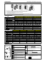
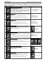
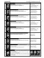
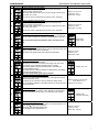
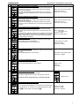
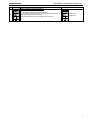
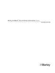
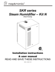
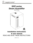
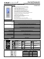
Fan Coil Thermostat
Specification & Installation Instructions
Fan Coil Thermostat with BACnet Communication Port
®
Features:
•
•
•
•
•
•
•
•
•
•
•
•
•
TFHB24F3XYZ2
Attractive modern look with large LCD and backlight
Icons driven information and 1 line of text information
2 Pipes Analog, ON/OFF or Floating or
4 Pipes Analog, ON/OFF with local re-heat function
Auto fan and ON/OFF function enable or disable
Internal humidity sensor and dehumidification sequence
(compensated by auto-activation of the reheat output)
Precise achieve temperature control with programmable PI function
Independent cooling & heating no occupancy set point
Lockable Set point / Control mode
Change over by contact or external temperature sensor
Celsius or Fahrenheit scale selectable
Anti-freeze protection
®
BACnet MS/TP @ 9600, 19200, 38400, 76800bps
Selectable device Instance and MAC Address via technician menu
Technical Data
TFHB24F3XYZ2
1 Digital input (24Vac or dry contact)
1 Analog input (external temperature sensor 10Kohms)
1 Analog input (change over 10Kohms or dry contact)
1 Fan analog or 3 Fan speed dry contracts 24Vac, 1A max 3A in-rush
2 Analog outputs (cooling and/or heating 0-10Vdc)
1 Analog output (local reheat 0-10Vdc)
2 Triacs output (cooling and/or heating) 24Vac, 0.3A max fused / triac
1 Triacs output (local reheat) 24Vac, 0.3A max fused / triac
22 to 26Vac 50/60Hz
1 VA max
Temperature: 10ºC to 40ºC [50ºF to 104ºF], Humidity: 10 to 65%RH
Temperature: ±0.4ºC [0.8ºF], Humidity: ±3.5%
0.5ºC to 5ºC [1ºF to 10ºF] adjustable (heat/cool/reheat independent)
0.3ºC to 5ºC [0.6ºF to 10ºF] adjustable (heat/cool/reheat independent)
0.8 mm2 [18 AWG] minimum
0ºC to 50ºC [32ºF to 122ºF]
-30ºC to 50ºC [-22ºF to 122ºF]
5 to 95% non condensing
IP 30 (EN 60529)
160 g. [0.36 lb]
Inputs
Outputs
Power supply
Power consumption
Set point range
Control accuracy
Proportional band
Dead band
Electrical connection
Operating temperature
Storage temperature
Relative Humidity
Degree of protection of housing
Weight
Presentation
Symbols on display
V MAX
..
HR
.
,.
V MIN
VDC
AM
PM
SEC
%RH
C
F
Cooling ON
33,66,100% output
A: Automatic
Heating ON
33,66,100% output
A: Automatic
Fan ON
3rd speed activated
A: Automatic
Communication
Status
Alarm status
Menu set-up Lock
Energy saving mode
Programming mode
(Technician setting)
%RH
Humidity
Dehumidification ON
Celsius scale
Cor F ºC:
ºF: Fahrenheit scale
Percentage of
humidity
Dimensions
B
Dimension
A
B
C
D
E
E
D
A
TFHB24F3XYZ2.doc/100217
C
Inches
2.85
4.85
1.00
2.36
3.27
Metric (mm)
73
123
24
60
83
1
TFHB24F3XYZ2
Specification & Installation Instructions
Mounting Instructions
A
B
C
D
E
CAUTION: Risk of malfunction. Remove power prior to separate thermostat cover from its base.
A. Remove the screw (captive) holding the base and the front cover of the thermostat.
B. Lift the front cover of the thermostat to separate it from the base.
C. Pull wire through the base hole.
D. Secure the base to the wall using wall anchors and screws (supplied). Make the appropriate connections.
E. Mount the control module on the base and secure using the screw.
Terminal Description
2 Pipe
Terminals
1
2
3
4
5
6
7
8
9
TB1
10
Fan option
Common
24 Vac
Common Triac
Triac output 1 (TO1)
Floating
output 1
Triac output 2 (TO2)
Triac output 3 (TO3) Reheat
Common Relay
Digital output 1 (DO1)
Digital output 2 (DO2)
Digital output 3 (DO3) /
Analog Fan Speed (AO4)
Occupancy Sensor (DI1)
External Temp. Sensor (AI1)
External Changeover (AI2)
Analog output 1 (AO1)
Analog output 2 (AO2)
Analog output 3 (AO3) Reheat
A+
Communication
Bport RS-485
11
12
13
14
15
16
17
18
4 Pipe
Terminals
1
2
3
4
5
6
7
8
9
TB1
10
Fan analog
1 spd
Low
Common
24 Vac
Common Triac
Triac output 1 (TO1) Floating
Triac output 2 (TO2) output 1
Triac output 3 (TO3) Reheat
Common Relay
Digital output 1 (DO1)
Digital output 2 (DO2)
Digital output 3 (DO3) /
Analog Fan Speed (AO4)
Occupancy Sensor (DI1)
Ext. Temp Sensor (AI1)
External Changeover (AI2)
Analog output 1 (AO1)
Analog output 2 (AO2)
Analog output 3 (AO3) Reheat
A+
Communication
port RS-485
B-
Fan analog
1 spd
Low
Low
Floating
analog
1 spd 2 spd 3 spd
Common
24 Vac
Common Triac
2 Pipe floating (close)
2 Pipe floating (open)
Local reheat (optional) (on/off or pulse)
Common Relay
High
High
Med
Fan analog
1 spd
Low
Low
Occupancy Sensor (optional)
External Temp. Sensor (optional)
External Changeover
Local reheat analog (optional)
Occupancy Sensor (optional)
External Temp. Sensor (optional)
External Changeover
Local reheat analog (optional)
BACnet
BACnet
BACnet
Common
24 Vac
Common Triac
Local reheat (optional) (on/off or pulse)
Common Relay
-
Low
On/Off
analog
1 spd 2 spd 3 spd
Common
24 Vac
Common Triac
2 Pipe on/off
Local reheat (optional) (on/off or pulse)
Common Relay
High
High
Med
Occupancy Sensor (optional)
External Temp. Sensor (optional)
External Changeover
2 Pipe analog
Local reheat analog (optional)
Cool & Heat Analog
analog 1 spd 2 spd 3 spd
Fan option
11
12
13
14
15
16
17
18
Analog
analog
1 spd 2 spd 3 spd
Common
24 Vac
Common Triac
Local reheat (optional) (on/off or pulse)
Common Relay
High
High
Med
-
Fan analog 1 spd
Cool Analog-Heat On/Off or pulse
Cool & Heat On/Off
analog 1 spd 2 spd 3 spd analog
1 spd 2 spd 3 spd
Common
24 Vac
Common Triac
4 Pipe on/off cool
4 Pipe (on/off or pulse) heat
Local reheat (optional) (on/off or pulse)
Common Relay
High High Med Low
Low
-
Fan analog 1 spd
Common
24 Vac
Common Triac
4 Pipe (on/off or pulse) heat
Local reheat (optional) (on/off or pulse)
Common Relay
High High Med Low
Low
-
Fan analog 1 spd
Cool On/Off - Heat Analog
analog 1 spd 2 spd 3 spd
Common
24 Vac
Common Triac
4 Pipe on/off cool
Local reheat (optional) (on/off or pulse)
Common Relay
High
High Med -
Low
Low
-
Fan analog 1 spd
High
High Med
Low
Low
Occupancy Sensor (optional)
External Temp. Sensor (optional)
4 Pipe analog cool
4 Pipe analog heat
Local reheat analog (optional)
Occupancy Sensor (optional)
External Temp. Sensor (optional)
Local reheat analog (optional)
Occupancy Sensor (optional)
External Temp. Sensor (optional)
4 Pipe analog cool
Local reheat analog (optional)
Occupancy Sensor (optional)
External Temp. Sensor (optional)
4 Pipe analog heat
Local reheat analog (optional)
BACnet
BACnet
BACnet
BACnet
Settings on PC Board
Triac Output Signal Selection (JP1)
JP1
Triac output
signal selector
24VAC
COM
JP1
JP1
TB1
24VAC
1
JP2
2
5
6
JP2
8
Mode selector
JP4
Fan output signal
selector
1 2 3
ON
Temperature
sensor
Dip
switch
9 10 11 12 13 14 15 16 17 18
PGM RUN
7
JP3
Jumper (JP1) on COMMON TRIAC:
All triac output signals are linked to common
triac.
Digital Output Signal Selection (JP2)
4
Connecting
strip TB1
3
Digital output
signal selector
COM
Jumper (JP1) on 24Vac:
All triac output signal is linked to 24 vac.
24VAC
JP2
COM
Jumper (JP2) on 24Vac:
All digital output signal is linked to 24Vac.
Jumper (JP2) on COMMON RELAY:
All digital output signals are linked to
common relay.
Fan Output Signal Selection (JP4)
Jumper (JP4) on top:
DO3
Pin 10 of TB1 is set to be digital output
AO4 signal (DO3).
JP4
Jumper (JP4) on bottom:
DO3
Pin 10 of TB1 is set to be analog output
AO4
signal (AO4).
Mode Selection (JP3)
Jumper (JP3) on RUN:
RUN Thermostat is in operation mode.
PGM Thermostat must be set in this mode to operate properly.
If not locked, set point, control mode and speed fan
(Heating & Cooling ON, Cooling only ON or Heating only
ON) may be modified by end user.
JP3
JP3
RUN
PGM
Jumper (JP3) on PGM:
Thermostat is set in Programming mode.
Refer to following section about all settings description
BACnet Dip Switch (DS1) - Optional
Pull up
120 ohm termination (Last node)
Pull down
JP4
ON
1
2
3
2
TFHB24F3XYZ2
Specification & Installation Instructions
Programming Mode
When in this mode this symbol
is displayed. Please press on button
to advance to the next program function, press on button
to return to preceding stage and press on button
or
to change value. You can leave the programming mode at any time,
changed values will be recorded.
Step
Display
Description
Values
Internal temperature sensor Calibration:
Display shows “inside temper sensor offset” and temperature read by
internal temperature sensor.
Range : 10 to 40ºC [50 to 104ºF]
You can adjust the calibration of the sensor by comparison with a known
(max. offset ± 5 ºC)
1
thermometer. For example if thermostat has been installed in an area
Increment: 0.1ºC [0.2ºF]
where temperature is slightly different than the room typical temperature
(thermostat place right under the air diffuser).
C
2
C
Minimum set point:
Display shows “adjust minimum user setpnt” and the minimum set point
temperature.
Please select the desired minimum set point temperature.
The minimum value is restricted by the maximum value. (step #3)
3
C
5
6
Maximum set point:
Display shows “adjust maximum user setpnt” and the maximum set point
Maximum range:
temperature.
10 to 40ºC [50 to 104ºF]
Please select the desired maximum set point temperature.
Increment: 0.5ºC [1ºF]
Default value: 30ºC [86ºF]
The maximum value is restricted by the minimum value. (step #2)
Locking the set point:
Display shows “user setpnt locked” and the status of the function.
You can lock or unlock the set point adjustment by end user. If locked,
“yes” and lock symbol will appear.
4
C
Minimum range:
10 to 40ºC [50 to 104ºF]
Increment: 0.5ºC [1ºF]
Default value: 15ºC [59ºF]
Adjust internal set point:
Display shows “adjust intern setpnt” and the set point temperature.
Select the desired set point temperature; this one should be within the
temperature range.
Lock symbol will appear if the set point was locked at the previous step.
Default value:
Unlocked (NO)
Set point range: 10 to 40ºC [50 to
104ºF]
Increment: 0.5ºC [1ºF]
Default value: 22ºC [72ºF]
Set point value is restricted by the minimum and maximum value. (step
#2 & 3)
Adjust the control mode:
Display shows “adjust temper control mode”. Cooling and heating
symbols are also displayed.
Select which control mode you want to authorize:
Automatic cooling and heating, cooling or heating, heating only or cooling
only.
If you want to authorize this entire mode, choose Automatic mode.
Default value:
Automatic cooling and heating
7
8
Set On/Off function enable or disable:
Display shows “enable on off control mode”.
You can enable or disable the On/Off function in control mode
adjustment by end user.
Set 2 pipe or 4 pipe:
Display shows “select 2 pipe 4 pipe system”. Cooling and heating
symbols are also displayed.
Select which number of pipes you want to use: 2 pipes or 4 pipes.
Default value:
Enable (YES)
Default value: 2 pipe
If you have selected the 4 pipes, go directly to step #15.
3
TFHB24F3XYZ2
Step
Display
Specification & Installation Instructions
Description
Set signal for 2 pipe system:
Display shows “select 2 pipe signal”. Cooling and heating symbols are
also displayed.
Select which signal output you want for your 2 pipe system.
You can choose analog, on/off or floating output.
If you select analog, AO1 will be set in automatic heat/cool change over.
If you select on/off, TO1 will be set in automatic heat/cool change over.
If you select floating, TO1 will be set close and TO2 open.
If you have selected analog signal, go directly to step #11.
If you have selected on/off signal, go directly to step #13.
Set floating time:
Display shows “set floating time in seconds” and the floating time value
(in seconds).
Please select desired value of the floating time signal.
9
10
Go to step #13.
Minimum voltage of the analog output:
Display shows “min vdc analog output” and the value of the minimum
voltage of the analog ramp.
Please select the desired value of the minimum voltage of the analog
ramp. (This is the “zero” value)
11
Values
Default value: Analog
Range: 15 to 250 sec.
Increment: 5 sec.
Default value: 100 sec.
Range: 0.0 to 10.0 Volt
Increment: 0.1 Volt
Default value: 0.0 Volt
The minimum value is restricted by the maximum value. (step #11)
Maximum voltage of the analog output:
Display shows “max vdc analog output” and the value of the minimum
voltage of the analog ramp.
Please select the desired value of the maximum voltage of the analog
ramp. (This is the “span” value)
12
Range: 0.0 to 10.0 Volt
Increment: 0.1 Volt
Default value: 10.0 Volt
The maximum value is restricted by the minimum value. (step #10)
13
14
15
16
C
Change over sensor selection:
Display shows “Ch over temper sensor”.
Please select which sensor is rewired to the analog input: SENs (external
change over sensor), NoCl (change over contact normally cool) or NoHt
(change over contact normally heat).
When normally cool “NoCL” is selected, if contact is closed heating mode
will be activated, if contact is opened cooling mode will be activated.
When normally heat “NoHt” is selected, if contact is closed cooling mode
will be activated, if contact is opened heating mode will be activated.
When change over external sensor “SENs” is selected, heating mode will
be activated when temperature read by external sensor is above the
Change Over Set Point temperature, and cooling mode will be activated
when temperature read by external sensor is under, see step #14.
If “SENs” is not selected, go directly to step #21.
Change over set point temperature: (If ‘’SENs’’ has been selected at step #13)
Display shows “Ch over setpnt temper” and the change over set point
temperature.
Please select the change over set point temperature.
Note: heating mode will be activated when temperature read by external
sensor is above the change over set point temperature, and cooling mode
will be activated when temperature read by external sensor is under.
Go to step #21.
Set signal for 4 pipe heating system: (If ‘’4P’’ has been selected at step #8)
Display shows “select 4 pipe heating signal”. Heating symbols is also
displayed.
Select which heating signal output you want for your 4 pipe system.
You can choose analog, on/off or pulse output.
If you select analog, AO2 will be set in heating.
If you select on/off or pulse, TO2 will be set in heating.
If you have selected on/off or pulse signal, go directly to step #18.
Minimum voltage of the heating output:
Display shows “min vdc analog output heating” and the value of the
minimum voltage of the heating ramp.
Please select the desired value of the minimum voltage of the heating
ramp. (This is the “zero” value)
Default value: SENs
Range: 10 to 40ºC [50 to 104ºF]
Increment: 0.5ºC [1ºF]
Default value: 24ºC [82ºF]
Default value:
Analog
Range: 0.0 to 10.0 Volt
Increment: 0.1 Volt
Default value: 0.0 Volt
The minimum value is restricted by the maximum value. (step #17)
4
TFHB24F3XYZ2
Step
Display
17
Specification & Installation Instructions
Description
Maximum voltage of the heating output:
Display shows “max vdc analog output heating” and the value of the
minimum voltage of the heating ramp.
Please select the desired value of the maximum voltage of the heating
ramp. (This is the “span” value)
Values
Range: 0.0 to 10.0 Volt
Increment: 0.1 Volt
Default value: 10.0 Volt
The maximum value is restricted by the minimum value. (step #16)
Set signal for 4 pipe cooling system: (If ‘’4P’’ has been selected at step #8)
Display shows “select 4 pipe cooling signal”. Cooling symbols is also
displayed.
Select which cooling signal output you want for your 4 pipe system.
You can choose analog or on/off output.
If you select analog, AO1 will be set in cooling.
If you select on/off, TO1 will be set in cooling.
If you have selected on/off signal, go directly to step #21.
Minimum voltage of the cooling output:
Display shows “min vdc analog output cooling” and the value of the
minimum voltage of the cooling ramp.
Please select the desired value of the minimum voltage of the cooling
ramp. (This is the “zero” value)
18
19
Default value: Analog
Range: 0.0 to 10.0 Volt
Increment: 0.1 Volt
Default value: 0.0 Volt
The minimum value is restricted by the maximum value. (step #20)
Maximum voltage of the cooling output:
Display shows “max vdc analog output cooling” and the value of the
minimum voltage of the cooling ramp.
Please select the desired value of the maximum voltage of the cooling
ramp. (This is the “span” value)
20
Range: 0.0 to 10.0 Volt
Increment: 0.1 Volt
Default value: 10.0 Volt
The maximum value is restricted by the minimum value. (step #19)
Set local reheat signal
Display shows “set local reheat signal”. Heating symbols is also
displayed.
Select which signal output you want for reheat.
You can choose OFF (no signal selected), ANALOG heating only,
ANALOG heating & fan, ON/OFF heating only, ON/OFF heating & fan,
PULSE heating only, PULSE heating & fan output.
21
If you select analog (& fan), AO3 will be set in reheat.
If you select on/off (& fan) or pulse (& fan), TO3 will be set in reheat.
If you have selected analog (& fan) signal, go directly to step #22.
If you have selected on/off (& fan) or pulse (& fan) signal, go directly
to step #24.
If you have selected OFF, go directly to step #26.
Default value: Off
Minimum voltage of the reheat output:
Display shows “min vdc analog output reheat” and the value of the
minimum voltage of the reheat ramp.
Please select the desired value of the minimum voltage of the reheat
ramp. (This is the “zero” value)
22
Range: 0.0 to 10.0 Volt
Increment: 0.1 Volt
Default value: 0.0 Volt
The minimum value is restricted by the maximum value. (step #23)
Maximum voltage of the reheat output:
Display shows “max vdc analog output reheat” and the value of the
minimum voltage of the reheat ramp.
Please select the desired value of the maximum voltage of the reheat
ramp. (This is the “span” value)
23
Range: 0.0 to 10.0 Volt
Increment: 0.1 Volt
Default value: 10.0 Volt
The maximum value is restricted by the minimum value. (step #22)
24
C
Reheat proportional band:
Display shows “control ramp reheat” and the value of the reheat
proportional band, heating symbol is also displayed.
Please select the desired value of reheat proportional band.
Proportional band range :
0.5 to 5.0ºC [1 to 10ºF]
Increment: 0.5ºC [1ºF]
Default value: 2.0ºC [4ºF]
5
TFHB24F3XYZ2
Step
25
26
27
28
29
Display
Specification & Installation Instructions
C
Description
Reheat dead band:
Display shows “control dead band reheat” and the value of the reheat
dead band, heating symbol is also displayed.
Please select the desired value of reheat dead band.
C
Proportional band in heating:
Display shows “control ramp HEATing” and the value of the heating
proportional band, heating symbol is also displayed.
Please select the desired value of heating proportional band.
C
Proportional band in cooling:
Display shows “control ramp cooling” and the value of the cooling
proportional band, cooling symbol is also displayed.
Please select the desired value of cooling proportional band.
C
C
Dead band in cooling:
Display shows “control dead band cooling” and the value of the cooling
dead band, cooling symbol is also displayed.
Please select the desired value of cooling dead band.
30
31
Integration time factor setting:
Display shows “adjust intgral time in seconds” and the time in seconds
for the integration factor compensation.
Please select the desired value of the integration factor compensation.
33
Dead band range :
0.3 to 5.0ºC [0.6 to 10.0ºF]
Increment: 0.1ºC [0.2ºF]
Default value: 0.3ºC [0.6ºF]
Proportional band range :
0.5 to 5.0ºC [1 to 10ºF]
Increment: 0.5ºC [1ºF]
Default value: 2.0ºC [4ºF]
Proportional band range :
0.5 to 5.0ºC [1 to 10ºF]
Increment: 0.5ºC [1ºF]
Default value: 2.0ºC [4ºF]
Dead band in heating:
Display shows “control dead band heating” and the value of the heating
Dead band range :
dead band, heating symbol is also displayed.
0.3 to 5.0ºC [0.6 to 10.0ºF]
Please select the desired value of heating dead band.
Increment: 0.1ºC [0.2ºF]
Default value: 0.3ºC [0.6ºF]
Anti-cycling delay cooling contact (protection for compressor):
Display shows “cooling anti cycle minutes” and the value (in minutes) of
the delay to activate / reactivate cooling contact.
Please select the desired value of the delay cooling contact.
32
Values
Dead band range :
0.3 to 5.0ºC [0.6 to 10.0ºF]
Increment: 0.1ºC [0.2ºF]
Default value: 0.3ºC [0.6ºF]
Range: 0 to 15 min.
Increment: 1 min.
Default value: 2 min.
Range: 0 to 250 seconds
Increment: 5 seconds
Default value: 0 seconds
Fan damping factor setting:
Display shows “adjust damping factor seconds” and the time in
seconds for the damping factor which will slow down the effect in change Range: 0 to 10 seconds
of demand for fan speed.
Increment: 1 seconds
Please select the desired value of the damping factor.
Default value: 0 seconds
Fan speed signal:
Display shows “select fan speed signal” and the speed of the fan. Fan
symbol is also displayed.
Select which fan speed signal or quantity of contact you want: Analog
signal, 1 speed, 2 speed or 3 speed.
If you want to use 1, 2 or 3 fan contact, select speed desired and go
directly to step #36.
Default value: 3 fan speed contact
6
TFHB24F3XYZ2
Step
Display
Specification & Installation Instructions
Description
Minimum voltage of the fan output:
Display shows “min vdc analog output fan” and the value of the
minimum voltage of the fan ramp.
Please select the desired value of the minimum voltage of the fan ramp.
(This is the “zero” value)
34
Values
Range: 0.0 to 10.0 Volt
Increment: 0.1 Volt
Default value: 0.0 Volt
The minimum value is restricted by the maximum value. (step #35)
Maximum voltage of the fan output:
Display shows “max vdc analog output fan” and the value of the
minimum voltage of the fan ramp.
Please select the desired value of the maximum voltage of the fan ramp.
(This is the “span” value)
35
Range: 0.0 to 10.0 Volt
Increment: 0.1 Volt
Default value: 10.0 Volt
The maximum value is restricted by the minimum value. (step #34)
Set fan speed automatic mode enable or disable:
Display shows “enable fan auto mode”. Fan
symbol is also displayed.
You can enable or disable the Automatic mode adjustment by end user.
36
If you selected to disable the automatic mode, go directly to step
#38.
Time out fan contact:
Display shows “fan auto timeout minutes” and the automatic shutoff delay
value (in minutes) when there is no demand.
Range: 0 to 15 min.
Please select the desired value of the automatic shutoff delay.
Increment: 1 min.
Default value: 2 min.
37
38
39
Default value:
Enable (YES)
C
External sensor selection:
Display shows “extern sensor temper”.
Please select which sensor is rewired to the analog input: OFF (input
none rewired), t10.0 (external temperature sensor 10.0 KΩ)
Default value: Off
When nothing “OFF” is selected, the thermostat is controlled by is
internal temperature sensor.
When external sensor “t10.0” is selected, the thermostat is controlled by
an external temperature sensor.
If you have selected OFF, go directly to step #40.
External temperature sensor Calibration:
Display shows “extern temper sensor offset” and temperature read by
external temperature sensor.
Range: 0 to 50ºC [41 to 122.0ºF]
If the sensor is not connected or short circuited, the display shows “Eror”.
(max. offset ± 5 ºC)
You can adjust the calibration of the external sensor by comparison with a Increment: 0.1ºC [0.2ºF]
known thermometer.
Occupancy contact:
Display shows “Select occ contact”. Moon symbol is also displayed.
You can choose NO (normally open) or NC (normally close) contact.
40
41
Default value:
Normally open (NO)
No occupancy derogation time :
Display shows “no occ delay overide minutes” and the derogation time in
minute. NSB symbol is also displayed.
Range: 0 to 180 min.
Please select the desired derogation time.
Increment: 15 min.
If no derogation time is desired select “0”.
Default value: 120 min.
7
TFHB24F3XYZ2
Step
42
43
Display
C
C
44
%RH
45
%RH
46
Specification & Installation Instructions
Description
Heating Set point during no occupancy:
Display shows “no occ heating setpnt” and the value of the heating set
point temperature during no occupancy period. Moon and heating
symbols are also displayed.
Please select the heating set point temperature during no occupancy.
The maximum value is restricted by the no occupancy cooling set point.
(step # 43)
Cooling set point during no occupancy:
Display shows “no occ cooling setpnt” and the value of the cooling set
point temperature during no occupancy period. Moon and cooling
symbols are also displayed.
Please select the cooling set point temperature during no occupancy.
The minimum value is restricted by the no occupancy heating set point.
(step # 42)
Internal humidity sensor offset Calibration:
Display shows “inside humidty sensor offset” and relative humidity
percentage read by internal humidity sensor. Humidify symbol is also
displayed.
You can adjust the calibration of the sensor by comparison with a known
humidistat. For example if humidistat has been installed in an area where
humidity is slightly different than the room typical humidity (humidistat
place right under the air diffuser).
Humidity control ramp:
Display shows “humidty control ramp” and the value of the humidity
ramp. Humidify symbol is also displayed.
Select the desired span for the humidify ramp.
Communication bauds rate:
Display shows “adjust comport bauds rate” and the value of the baud
rate in kBds.
Select the desired bauds for communication.
Communication MSTP/Mac address:
Display shows “adjust MSTP Mac address”.
Select the desired MSTP/Mac for communication.
47
Values
Range: 10.0 to 40.0ºC [50 to 104ºF]
Increment: 0.5ºC [1ºF]
Default value: 16.0ºC [61ºF]
Range: 10.0 to 40.0ºC [50 to 104ºF]
Increment: 0.5ºC [1ºF]
Default value: 28.0ºC [82ºF]
Range: 10 to 90%RH
(max. offset ± 5%)
Increment: 0.1%RH
0.0%RH no humidity sensor
Set point range: 3 to 10%RH
Increment: 0.5%RH
Default value: 5.0%RH
Range: 9600, 19200, 38400, 76800
Default value: 9.6 kBds
Range: 0 to 254
Increment: 1
Default value: 1
Communication device instance:
Display shows “adjust device instanc 0153000”.
If you want to change the device, select “yes” and go to next step.
48
If you do not want to change the device, go directly to step #1.
Communication device instance (cont’d):
Display shows the device address value.
You can modify the device address by incrementing or decrementing the
49
blinking digit with “∆” or “∇”buttons. To modify following digit on right
, to return to digit on the left press
.
press
Default value: no
Range: 0 to 4194302
Increment: 1 by digit
Default value: 0153000
8
TFHB24F3XYZ2
Step
50
Display
Specification & Installation Instructions
Description
Enable or disable anti-freeze protection:
Display shows “enable anti freeze protect”.
You can enable or disable the Anti-freeze function.
When enabled, if temperature drop to 4ºC [39ºF], heat and reheat will
start even if thermostat is in OFF mode.
Heat and reheat will stop when temperature reach 5ºC [41ºF].
Values
Default value:
Disable (NO)
9
TFHB24F3XYZ2
Operation Mode
Step
A
Specification & Installation Instructions
Description
Display
At powering up, thermostat will light display and activate all LCD segments during 2 seconds.
Illuminating the LCD.
To illuminate the LCD, you just have to push onto any of the 4 buttons. LCD will light for 4 seconds.
Temperature display
In operation mode, thermostat will automatically display the temperature reading for 8 seconds.
Humidity reading will be displayed for 2 seconds.
If “OFF”, “- - -” and alarm symbol are displayed, the temperature sensor is not connected or short
circuited.
C
To change the scale between ºC and ºF, press on both ∆ and ∇ for 3 seconds.
Temperature set point display and adjustment
To display the set point, press two times on ∆ or ∇. Set point will be displayed during 3 seconds.
B
To adjust set point, press on ∆ or ∇ while the temperature set point is displayed.
Note: If set point adjustment has been locked,
C
C
%RH
%RH
symbol will be displayed.
Humidity set point display and adjustment
button for 5 seconds. When in this mode
Humidity set point menu will be access by pushing
“ADJUST HUMIDTY SETPNT” is displayed. Set point will be displayed during 5 seconds.
C
D
To adjust set point, press on ∆ or ∇ while the humidity set point is displayed. If you press on button
or
, you will leave the humidity set point menu.
Humidity display
In operation mode, when humidity reading is displayed for 2 seconds, if “- - -” and alarm symbol are
displayed, the humidity sensor is not connected or short circuited.
No occupancy mode :
When thermostat is in no occupancy mode, moon symbol is displayed, so set point for cooling
and/or heating are increased as per the setting made in programming mode.
If not locked, no occupancy mode can be derogated for a predetermined period by pressing onto
any of the 3 buttons. During period of derogation the symbol will flash. If does not flash, the
derogation period is finished or the no occupancy mode derogation has been locked in
programming mode.
Control mode selection :
To change the control mode, press on
can choose one of the following:
E
9
9
9
9
C
. Control mode will be displayed during 5 seconds. You
Automatic Cooling or Heating
Cooling and Heating OFF
Cooling only
Heating only
Note: These selections can vary according to the choice made on steps #6 & #7.
Fan speed mode selection:
To change the fan speed mode, press on
You can choose one of the following:
F
9
9
9
9
. Fan speed mode will be displayed during 5 seconds.
Automatic speed (if not disable in programming mode)
Low speed
Medium speed
High speed
Note: These selections can vary according to the choice made on step #33 & #36.
Recycling at end of life
®
At end of life, please return the thermostat to your Neptronic local distributor for recycling. If you need to find the nearest Neptronic
authorized distributor, please consult www.neptronic.com.
®
10