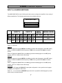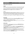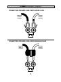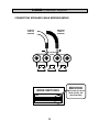
1
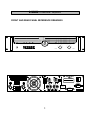
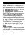
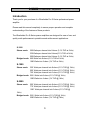
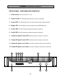
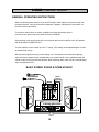
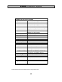
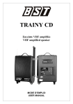
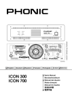
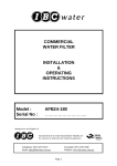
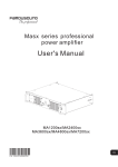
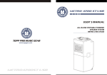
PROFESSIONAL POWER AMPLIFIERS
Power
Protect
Bridge
Peak A
Peak B
Signal
4
5
6
3
2
Professional Amplifier
CH. A
4
7
8
1
9
0
10
5
Signal
6
3
7
2
8
1
9
0
10
CH. B
S-SERIES
Professional Amplifiers
TABLE OF CONTENTS
PAGE
1.
FRONT AND REAR PANEL REFERENCE DRAWINGS
2.
WARNINGS AND WARRANTY INFORMATION
3.
INTRODUCTION
4.
GETTING STARTED
5.
FRONT PANEL FEATURES AND CONTROLS
6.
REAR PANEL FEATURES AND CONTROLS
7.
INPUT “A” AND “B” MODE SWITCHES
8.
MODE SWITCH OPERATION
9.
OUTPUT “A” AND “B” WIRING OPTIONS
10.
USING OUTPUT “A” NL-4 FOR BOTH OUTPUTS
BRIDGED MONO MODE NL-4 WIRING
11.
BINDING POST WIRING OPTIONS
CONNECTING BARE ENDED SPEAKER CABLE LEADS
12.
CONNECTING SPEAKER CABLE WITH SPADE LUGS
CONNECTING SPEAKER CABLE WITH BANANA PLUGS
13.
CONNECTING SPEAKER CABLE / BRIDGED-MONO
14.
GENERAL OPERATING INSTRUCTIONS
15.
S-1000 SPECIFICATIONS
16.
S-1500 SPECIFICATIONS
17.
S-2500 SPECIFICATIONS
BACK COVER: CONTACT INFORMATION
S-SERIES
Professional Amplifiers
FRONT AND REAR PANEL REFERENCE DRAWINGS
Protect
Power
Bridge
Peak A
Signal
Peak B
4
5
6
3
2
CH. A
Professional Amplifier
INPUT
MODE
BRIDGE MODE
SW1
SW2
SW3
SW4
SW5
SW6
SW7
SW8 SW9
SW10 SW11 SW12
N/C
ON
30Hz
OFF
ON
30Hz
OFF
PARALLEL
OFF
50Hz
ON
OFF
50Hz
ON
STEREO
ON
OFF
LIMITER
LO
CUT
LO
CUT
LIMITER
LO
CUT
LO
CUT
INPUT A
N/C
INPUT B
MODE SWITCHES
INPUT A
ON
INPUT B
OUTPUT A
7
2
9
0
Signal
6
8
1
10
9
0
10
CH. B
OUTPUT B
1+
BREAKER
1-
OUTPUT B
POS
NEG
2+
2-
POS
NEG
1+
2+
MODEL S-SERIES
OUTPUT B
BRIDGED MONO
POS
NEG
1+
1-
Professional Power Amplifier
BRIDGED
MONO
WWW.WHARFEDALEPRO.COM
BRIDGE MONO MODE
-USE INPUT A LIMITER / FILTER
AND LEVEL CONTROL
-SET INPUT B LIMITER / FILTER
AND LEVEL CONTROL TO OFF
POWER
OUTPUT POWER PER
CHANNEL /
IMPEDANCE 770w / 4Ώ
1= GROUND SHIELD
BRIDGED MONO:
4Ώ MIN LOAD
2= HOT (+)
3= COLD (-)
_
SLEEVE = GROUND SHIELD
¼”
8
1
5
3
OUTPUT A
1 2 3 4 5 6 7 8 9 10 11 12
XL
R
4
7
TIP=HOT(+)
RING=COLD(-)
A
_
+ +
BRIDGED
1
+ B
_
CAUTION
AC 100V-120V~60Hz
S-SERIES
Professional Amplifiers
WARNINGS AND WARRANTY INFORMATION
Unpacking: All Wharfedale Pro products are fully tested before leaving the factory.
After unpacking, please inspect the unit. In the event of any noticed damage due to
shipping, contact your dealer and the shipping provider immediately to file a shipping
damage claim. Retain the shipping carton and all packaging material in case the unit
needs to be returned.
1.
READ ALL INSTRUCTIONS carefully and become familiar with the features
and functions of this product before operating it.
2.
RETAIN THESE INSTRUCTIONS for future reference.
3.
COMPLY WITH ALL WARNINGS – All warnings and instructions for this
product should be adhered to.
4.
USING AMPLIFIERS – In order to avoid damage to equipment, it is advisable
to establish and follow a routine for powering up and powering down a sound system.
With all system components connected, turn on source equipment (mixers, signal
processors, record and playback units, etc.) BEFORE powering up amplifiers.
Transient voltages from powering up source equipment can damage speakers if
amplifiers are turned on. Make sure that amplifier volumes are set to their minimum
settings and power up any system amplifiers LAST. It is recommended that all system
components be allowed to stabilize for several seconds before any source signals are
introduced or level setting adjustments are made. Similarly, when shutting systems
down, turn all amplifiers off first, before powering down any other system components.
5.
CABLES – Do not use shielded or microphone cables for connection between
amplifiers and speakers. Use only approved speaker cables with proper connectors.
6.
CAUTION – The S Series professional amplifiers are capable of generating
very high sound pressure levels. Use care with operation to avoid exposure to
excessive volume levels that can cause permanent hearing damage if operated to
extremes.
7.
SERVICE – There are no user serviceable parts inside this product. Users
should not attempt to service this product. Potential dangerous voltages and shock
hazards are present inside this product. Warranty nullification could result if this is
attempted.
Wharfedale Pro Limited Warranty
*Wharfedale Pro SR Series amplifiers are warranted to the original purchaser against
manufacturing or materials defects for a period of one year from the original date of
purchase. Faults arising from misuse, unauthorized modifications or accidents are not
covered under this warranty. No other warranty is expressed or implied. In the event of
malfunction, contact your authorized Wharfedale Pro dealer or distributor for
information.
*Be aware that warranty details may differ from country to country. Contact your dealer
or distributor for information.
2
S-SERIES
Professional Amplifiers
Introduction
Thank you for your purchase of a Wharfedale Pro S-Series professional power
amplifier.
Please read this manual completely to ensure proper operation and complete
understanding of the features of these products.
The Wharfedale Pro S-Series power amplifiers are designed for ease of use, and
quality audio performance in portable sound reinforcement applications.
S-1000
Stereo mode:
200 Watts per channel into 8 ohms (0.1% THD at 1kHz)
330 Watts per channel into 8 ohms(0.1% THD at 1kHz)
500 Watts per channel into 8 ohms (0.1% THD at 1kHz)
Bridged mode: 660 Watts into 8 ohms (0.1% THD at 1kHz)
1000 Watts into 8 ohms (1% THD at 1kHz)
S-1500
Stereo mode:
320 Watts per channel into 8 ohms (0.1% THD @ 1kHz)
500 Watts per channel into 4 ohms (0.1% THD @ 1kHz)
750 Watts per channel into 2 ohms (0.1% THD @ 1kHz)
Bridged mode: 1000 Watts into 8 ohms (0.1% THD @ 1kHz)
1500 Watts into 4 ohms (1% THD @ 1kHz)
S-2500
Stereo mode:
500 Watts per channel into 8 ohms (0.1% THD @ 1kHz)
770 Watts per channel into 4 ohms (0.1% THD @ 1kHz)
1250 Watts per channel into 2 ohms (0.1% THD @
1kHz)
Bridged mode: 1500 Watts into 8 ohms (0.1% THD @ 1kHz)
2500 Watts into 4 ohms (1% THD @ 1kHz)
3
S-SERIES
Professional Amplifiers
Getting Started
1. AC Power Connections
All S-Series power amplifiers are equipped with an internal AC power supply. Connect the
appropriate grounded IEC power cable to the power amp BEFORE connecting it to the power
outlet.
It is important to allow adequate ventilation to the powered mixer as it may become warm
during extended periods of operation.
Each S-Series amp is shipped with the correct power cable for the country in which it is to be
used. The S-Series amps are NOT to be used in a country using a different source supply
voltage other than for which it is designed. Note the operating voltage shown near the AC
power cord jack and ONLY connect this unit to the appropriate AC source voltage.
2. Packing
The packaging has been designed protect the mixer during transit. If any shipping damage has
occurred, consult your dealer and the shipping provider.
3. Safety
Avoid excessive heat, humidity, dust and vibration. Store and operate the power amplifier away
from high temperatures or humidity. Also, avoid locations which may be subject to excessive
dust and vibration / physical shocks that could cause mechanical damage to the amp.
WARNING: REFER ALL MAINTENANCE, REPAIRS AND MODIFICATIONS TO QUALIFIED
SERVICE PERSONNEL! THIS PRODUCT CONTAINS NO USER-SERVICEABLE PARTS!
For the protection of the amplifier and other audio equipment, always turn off the power on the
amplifier and other system components before connecting or disconnecting audio cables.
4. Warranty
The S-Series power amplifiers are covered, by limited warranty, of any defects in workmanship
for a period of one year from the date of purchase. This warranty is non-transferable and
applies only to the original purchaser. If any warranty related issues occur, contact your dealer.
4
S-SERIES
Professional Amplifiers
FRONT PANEL - FEATURES AND CONTROLS
1. Power switch: Push to turn power on or off.
2. Power On LED: This LED lights when the power is on for the amplifier.
3. Protect LED: This LED will light up when a fault is detected in the amplifier operation.
4. Bridge LED: This LED lights up when the amplifier is set to BRIDGED mode.
5. Peak A LED: This LED indicates overload of the signal of Channel A
6. Peak B LED: This LED indicates overload of the signal of Channel B
7. Channel A Signal Present LED: Indicates presence of signal on Channel A.
8. Channel B Signal Present LED: Indicates presence of signal on Channel B.
9. Channel A Signal Level Control: This knob controls the output level of Channel A.
10. Channel B Signal Level Control: This knob controls the output level of Channel B.
2
Power
3 4 5 6
Protect
Bridge
Peak A
8
7
Peak B
Signal
4
5
6
3
2
CH. A
Professional Amplifier
8
1
9
0
10
9
1
5
4
7
5
Signal
6
3
7
2
8
1
9
0
10
10
CH. B
S-SERIES
Professional Amplifiers
REAR PANEL – FEATURES AND CONTROLS
1. INPUT “A” XLR and ¼” Balanced Line Input jacks: These XLR inputs are
balanced input jacks and ¼” TRS (Tip / Ring / Sleeve) balanced / unbalanced inputs. These
jacks are designed to be connected to +4dBu balanced or unbalanced line level sources.
2. INPUT “B” XLR and ¼” Balanced Line Input jacks
3. MODE Switches: Allows for selection of various operating modes for the amplifier.
4. Cooling Fan: This fan provides air flow and cooling to the internal amplifier components.
5. OUTPUT “A” Binding Post Outputs: Positive and negative binding posts are
provided for connection to speakers via banana plug, spade terminal or bare wire connections.
6. OUTPUT “B” Binding Post Outputs
7. OUTPUT “A” Speakon Output Jacks: Speakon®-type connector provided for
connection of the output of the amplifier to speakers. These outputs are rated for speaker
connections of 4 to 8 ohms.
8. OUTPUT “B” Speakon Output Jacks
9. AC Power jack: Plug the appropriate A/C power cord to this connector.
WARNING: DO NOT ATTEMPT TO BYPASS THE GROUND CONNECTION OF THE POWER CORD!
10. Circuit Breaker: Provides short circuit protection to amplifier outputs.
3
INPUT A
4
INPUT B
S
W
1
S
W
1
S
W
1
S
W
1
S
W
1
S
W
1
S
W
1
S
W
1
S
W
1
S
W
1
L
I
M
I
T
E
R
S
W
1
L
O
S
W
1
L
O
C
U
T
C
U
T
S
W
1
S
W
1
S
W
1L
I
M
I
T
E
R
S
W
1
S
W
1
S
W
1
L
O
C
U
T
S
W
1
S
W
1
S
W
1
BRIDGE
MODE
SW8 SW9
SW10 SW11
SW12
PARALLEL
STEREO
ON
OFF
L
O
MODE
SWITCHES
INPUT A
INPUT
MODE
ON
8
10
OUTPUT A
OUTPUT B
BREAKER
OUTPUT A
1+
1OUTPUT B
POS
NEG
2+
INPUT B
7
OUTPUT B
2-
POS
NEG
1+
2+
1-
MODEL S-SERIES
Professional Power
Amplifier
WWW.WHARFEDALEPRO.COM
BRIDGE MONO MODE
-USE INPUT A LIMITER/
FILTER AND LEVEL CONTROL
-SET INPUT B LIMITER/FILTER
AND LEVEL CONTROL TO OFF
X
L
R
NEG
1+
BRIDGED
MONO
1 2 3 4 5 6 7 8 9 1011 12
POWER
OUTPUT POWER
PER CHANNEL /
IMPEDANCE 770w /
4Ώ
1= GROUND SHIELD
BRIDGED MONO:
4Ώ MIN LOAD
2= HOT (+)
_
3= COLD (-)
SLEEVE=GROUND SHIELD
¼
”
POS
BRIDGED MONO
TIP=HOT(+)
A
++
_ +
B
_
CAUTION
AC 100V120V~60Hz
BRIDGED
RING=COLD(-)
1
5
2
6
6
6
S-SERIES
Professional Amplifiers
INPUT A & B MODE SWITCHES
The MODE SWITCHES for the S-2500 provide the means to configure the amplifier in for a variety of
different applications. The following legend shows the available selections.
MODE SWITCHES
ON
1 2 3 4 5 6 7 8 9 10 11 12
INPUT A
SW1 SW2 SW3
N/C ON 30Hz
N/C OFF 50Hz
LO
LIMITER
CUT
SW4
OFF
ON
LO
CUT
INPUT B
SW5 SW6
ON 30Hz
OFF 50Hz
LO
LIMITER
CUT
SW7
OFF
ON
LO
CUT
INPUT
MODE
SW8 SW9
PARALLEL
STEREO
BRIDGE MODE
SW10 SW11 SW12
ON
OFF
Switch 1: is not used
INPUT A
Switch 2: Engages the signal LIMITER in the ON (up) position and disengages it when OFF (down).
Switch 3: Selects the LO CUT roll off frequency of 30Hz in the up position and 50Hz in the down
position.
Switch 4: Engages the LO CUT filter in the ON (up) position and disengages it in the OFF (down)
position. (This is a -12dB per octave filter slope).
INPUT B
Switch 5: Engages the signal LIMITER in the ON (up) position and disengages it when OFF (down).
Switch 6: Selects the LO CUT roll off frequency of 30Hz in the up position and 50Hz in the down
position.
Switch 7: Engages the LO CUT filter in the ON (up) position and disengages it in the OFF (down)
position. (This is a -12dB per octave filter slope).
OUTPUTS
Switches 8 & 9: Engage the PARALLEL input signal configuration in the up position and engages
STEREO input configuration when down.
Switch 10 , 11 & 12: Selects the BRIDGE output mode in the up position and disengages it (normal
stereo mode) in the down position.
7
S-SERIES
Professional Amplifiers
MODE SWITCH OPERATION
LIMITER
A limiter is a circuit that prevents signal overload and distortion in an audio signal path. When engaged,
the internal limiter circuit will keep the audio signal from going over a preset level threshold, thereby
helping to prevent signal distortion within the amplifier and in the speaker system. The limiter also
serves to prevent speaker damage. The limiter function can be engaged by engaging MODE
SWITCHES SW2 (for INPUT A) and SW5 (for INPUT B) in the up “ON” position.
LO CUT
MODE SWITCHES SW3, SW4 (for INPUT A) and SW6, SW7 (for INPUT B) provide the options of low
frequency filtering starting at the 30Hz and 50Hz frequency ranges and frequencies below those points.
These filters “roll off” the lower bass frequency range to help eliminate unwanted “boominess” in the
sound system with a -12dB per octave slope. MODE Switch SW4 engages the “LO CUT” filter and
Switch SW3 selects between the 30Hz (in the up, “ON” position) and 50Hz (in the down “OFF” position).
INPUT MODE
The INPUT MODE switches select the operating mode of the amplifier. STEREO mode allows the unit
to function as a two channel amplifier with each input (INPUT A & INPUT B) routed to a separate
amplifier output (OUTPUT A & OUTPUT B), respectively.
PARALLEL mode sums the signals of INPUT A and INPUT B together and routes the combined signal
to both OUTPUT A and OUTPUT B.
BRIDGE MODE
This mode allows you to combine the amplifier outputs for more power. MODE SWITCHES #10, 11
and 12 control this function. BRIDGE MODE can provide nearly three times more power output than
operating the amp in STEREO mode.
When in BRIDGE MODE, only the controls on INPUT A are functional. INPUT B MODE SWITCH
settings have no affect on the operation of the amplifier when in BRIDGE MODE and the volume control
for INPUT B should be set all the way down when operating in this mode.
BRIDGE MODE provides a single 4Ω or 8Ω output for connection to an equivalent speaker impedance
load. Be aware of the increased power output that BRIDGE MODE provides and be sure that all
speakers have appropriate power handling capabilities before making connections otherwise speaker
damage may occur. Speaker wiring for BRIDGE MODE is made via the two middle output binding post
terminals. See pages 10 and 13 for BRIDGE MODE wiring details.
8
S-SERIES
Professional Amplifiers
OUTPUT “A” AND “B” WIRING OPTIONS
Output wiring options consist of NL-4 “Speakon®-type” female connectors for the left and right outputs
along with industry standard binding posts for direct wiring connections or wiring with banana plugs.
OUTPUT A
OUTPUT B
OUTPUT A
1+
1-
OUTPUT B
POS
NEG
2+
OUTPUT B
2-
POS
NEG
1+
1-
BRIDGED MONO
POS
NEG
1+
2+
BRIDGED
MONO
_
A
_
+ +
+ B
_
BRIDGED
NL-4 CONNECTOR WIRING
OUTPUT “A” & “B” FULL RANGE:
2+
2FULL RANGE
1+ = POSITIVE
1 - = NEGATIVE
Negative
lead from
amplifier
1-
FULL
RANGE
1+
Positive
lead from
amplifier
9
S-SERIES
Professional Amplifiers
USING OUTPUT JACK “A” NL-4 FOR BOTH OUTPUTS
Positive lead
from OUTPUT B
2+
Negative lead
from OUTPUT B
2-
Negative lead
from OUTPUT A
1-
1+
DUAL
OUTPUT
Positive lead
from OUTPUT A
FULL RANGE SHARED OUTPUT
1+ = POSITIVE - OUTPUT A
1 - = NEGATIVE - OUTPUT A
2+ = POSITIVE - OUTPUT B
2 - = NEGATIVE - OUTPUT B
BRIDGED-MONO MODE NL-4 WIRING * :
Negative
lead from
amplifier
USING OUTPUT “A” NL-4
2+
2-
BRIDGED MODE
1+ = POSITIVE
2+ = NEGATIVE
1+
1-
BRIDGED
MONO
Positive
lead from
amplifier
* SEE DETAILS ABOUT BRIDGE MODE
SWITCH SETTINGS ON PAGE 7 and 13
10
S-SERIES
Professional Amplifiers
BINDING POST WIRING OPTIONS
BRIDGED
MONO
A
B
BRIDGE
As shown in the graphic above, the stereo and bridged mono applications can be connected as
indicated. Binding post wiring can be done with spade connectors, bare wire ends tightened into
the binding posts or via banana plugs inserted into the end of the binding posts.
CONNECTING BARE ENDED SPEAKER CABLE LEADS
NEGATIVE
LEAD TO
SPEAKER
POSITIVE
LEAD TO
SPEAKER
_
A
+
Strip away approximately ½” (12mm) of insulation from the speaker wire. Twist the bare copper wire
ends tightly. Unscrew each binding post, insert the wire into the hole in the metal portion of the binding
post and tighten the binding post securely. Be care of stray wire strands that could cause shorts.
11
S-SERIES
Professional Amplifiers
CONNECTING SPEAKER CABLE WITH SPADE LUGS
NEGATIVE
LEAD TO
SPEAKER
POSITIVE
LEAD TO
SPEAKER
_
A
+
CONNECTING SPEAKER CABLE WITH BANANA PLUGS
POSITIVE
LEAD TO
SPEAKER
NEGATIVE
LEAD TO
SPEAKER
_
A
12
+
S-SERIES
Professional Amplifiers
CONNECTING SPEAKER CABLE BRIDGED-MONO
POSITIVE
LEAD TO
SPEAKER
NEGATIVE
LEAD TO
SPEAKER
BRIDGED
MONO
_
A
_
+ +
+
B
_
BRIDGE
MODE SWITCHES
ON
1 2 3 4 5 6 7 8 9 101112
13
BRIDGED-MONO
MODE REQUIRES
SWITCH #10, #11 & #12
TO BE IN THE “UP”
(ON) POSITION
S-SERIES
Professional Amplifiers
GENERAL OPERATING INSTRUCTIONS
Make sure that the power switch is set to the OFF position while making connections to and from
the power amplifier. Connect all external components. Speakers, Microphones, instruments, etc.
Check for secure connections.
Turn all level controls down on mixers, amplifiers and signal processing devices.
Connect the A/C power cord to the power outlet of the amplifier.
After powering up all other devices first, turn the power switch on the amplifier to the ‘ON’ position
and verify that the POWER LED is lit.
Turn the amplifier volume control up to the “7” setting. (This setting can be adjusted higher or lower,
as needed, after set-up).
With the source signal present (a person singing in to a microphone or and instrument playing),
adjust the various signal levels as needed. Make any needed overall volume adjustments with the
volume control on the mixer and the amplifier. When powering down, make sure any external power
amps are switched off first.
BASIC STEREO SOUND SYSTEM HOOKUP
MICROPHONES
MIXER
OUTPUTS
MIXER
S-SERIES AMPLIFIFER
AMP
INPUTS
A
B
MODEL S-SERIES
INPUT B
Professional Power Amplifier
WWW.WHARFEDALEPRO.COM
SPEAKER A
SPEAKER B
AMP
OUTPUTS
14
S-SERIES
Professional Amplifiers
S-1000 SPECIFICATIONS
Output Power
Stereo:
180W+180W/8Ω (0.1% THD at 20Hz-20kHz)
300W+300W/4Ω(0.1% THD at 20Hz-20kHz)
200W+200W/8Ω (0.1% THD at 1kHz)
330W+330W/4Ω (0.1% THD at 1kHz)
500W+500W/2Ω (0.1% THD at 1kHz)
Bridged:
600W/8Ω (0.1% THD at 20Hz-20kHz)
660W/8Ω (0.1% THD at 1kHz
1000W/4Ω (1% THD at 1kHz)
<0.02%
THD+N
Frequency Response 20Hz-20kHz 0/-0.5dB
10Hz-40kHz 0/-2dB
-95dB
Hum and Noise
33dB
Voltage Gain
+4dBu
Input Sensitivity
Maximum Input Level +22dBu
Balanced: 20kΩ; Unbalanced: 10kΩ
Input Impedance
Controls
Low Cut Filter: 50Hz -6dB(-12dB/oct); 30Hz -6dB(-12dB/oct)
SIGNAL Indicators: Turns on approx -35dBu
CLIP indicators: Turns on approx 350Wx2/4Ω output
Limiter: Turns on approx 350Wx2/4Ω output
Amplifier Protection: Mute function; DC detection; Overload and
short detection; Temperature detection
Class AB complementary linear output
Power Amp Type
AC100V / 120V / 220V / 240V, 50/60Hz
AC Power Options
Dimensions (HxWxD)
mm 96mm x 482.6mm x 427mm
inches 3.8" x 19" x 16.8"
Weight
kg 15.4kg
lbs 33.9lbs
Product details, features and specifications subject to change without notice.
15
S-SERIES
Professional Amplifiers
S-1500 SPECIFICATIONS
Output Power
Stereo:
300W+300W/8Ω (0.1% THD at 20Hz-20kHz)
450W+450W/4Ω (0.1% THD at 20Hz-20kHz)
320W+320W/8Ω (0.1% THD at 1kHz)
500W+500W/4Ω (0.1% THD at 1kHz)
750W+750W/2Ω (0.1% THD at 1kHz)
Bridged:
900W/8Ω (0.1% THD at 20Hz-20kHz)
1000W/8Ω (0.1% THD at 1kHz
1500W/4Ω (1% THD at 1kHz)
<0.02%
THD+N
Frequency Response 20Hz-20kHz 0/-0.5dB
10Hz-40kHz 0/-2dB
-95dB
Hum and Noise
33dB
Voltage Gain
+4dBu
Input Sensitivity
Maximum Input Level +22dBu
Balanced: 20kΩ; Unbalanced: 10kΩ
Input Impedance
Controls
Low Cut Filter: 50Hz -6dB(-12dB/oct); 30Hz -6dB(-12dB/oct)
SIGNAL Indicators: Turns on approx -35dBu
CLIP indicators: Turns on approx 490Wx2/4Ω output
Limiter: Turns on approx 506Wx2/4Ω output
Amplifier Protection: Mute function; DC detection; Overload and
short detection; Temperature detection
Class AB complementary linear output
Power Amp Type
AC100V / 120V / 220V / 240V, 50/60Hz
AC Power Options
Dimensions (HxWxD)
mm 96mm x 482.6mm x 427mm
inches 3.8" x 19" x 16.8"
Weight
kg 16.3kg
lbs 35.9lbs
Product details, features and specifications subject to change without notice.
16
S-SERIES
Professional Amplifiers
S-2500 SPECIFICATIONS
Output Power
Stereo:
490W+490W/8Ω (0.1% THD at 20Hz-20kHz)
700W+700W/4Ω (0.1% THD at 20Hz-20kHz)
500W+500W/8Ω (0.1% THD at 1kHz)
770W+770W/4Ω (0.1% THD at 1kHz)
1250W+1250W/2Ω (0.1% THD at 1kHz)
Bridged:
1400W/8Ω (0.1% THD at 20Hz-20kHz)
1500W/8Ω (0.1% THD at 1kHz
2500W/4Ω (1% THD at 1kHz)
<0.03%
THD+N
Frequency Response 20Hz-20kHz 0/-0.5dB
10Hz-40kHz 0/-2dB
-95dB
Hum and Noise
33dB
Voltage Gain
+4dBu
Input Sensitivity
Maximum Input Level +22dBu
Balanced: 20kΩ; Unbalanced: 10kΩ
Input Impedance
Controls
Low Cut Filter: 50Hz -6dB(-12dB/oct); 30Hz -6dB(-12dB/oct)
SIGNAL Indicators: Turns on approx -35dBu
CLIP indicators: Turns on approx 800Wx2/4Ω output
Limiter: Turns on approx 840Wx2/4Ω output
Amplifier Protection: Mute function; DC detection; Overload and
short detection; Temperature detection
Class H complementary linear output
Power Amp Type
AC100V / 120V / 220V / 240V, 50/60Hz
AC Power Options
Dimensions (HxWxD)
mm 96mm x 482.6mm x 427mm
inches 3.8" x 19" x 16.8"
Weight
kg 17.7kg
lbs 39lbs
Product details, features and specifications subject to change without notice.
17
Wharfedale International LTD.
IAG HOUSE
Sovereign Court, Ermine Business Park,
Huntingdon, Cambs,
PE29 6XU, England
www.wharfedalepro.com
IAG Professional reserves the right to alter or improve
specifications without notice.
All rights reserved © 2007 Wharfedale Pro
Wharfedale Pro is a member of the International Audio Group