1
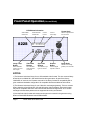
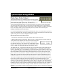
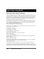
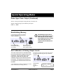
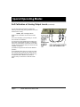
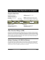
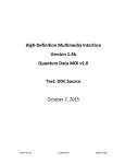
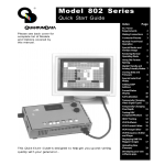
MODEL 822S
Programmable Monochrome
Video Signal Generator
Table of
Contents
Making Connections .... 2
Proper Video
Termination ................... 3
Front Panel Operation ... 4
Special Operating
Mode (Probe Pulse) ..... 5
Special Operating
Mode (Reinitializing
Memory) ...................... 7
Special Operating
Mode (Self Calibration of
Analog Output Levels) .. 7
Programming and
Operating via
Computer ..................... 9
Specifications ............. 10
Support and Service
Contact Information ..... 12
Quick Start
Guide
Quantum Data, Inc.
68-00183 Rev. C
This Quick Start Guide is designed to help you get up and running
quickly with your video generator. Detailed information on
programming and operating the generator via its communications
ports can be found in the VGM software’s on-line help file.
Quantum Data, Inc.
Page 1
Making Connections (Power & Test Signals)
AC Mains
Input & Switch
85 - 264 VAC
48 - 440 Hz Sine
300 Watts Max.
Rear View of
Model 822S
Analog Video Output
50 Ohm Differential
Pixel Clock Outputs
50 Ohm Differential ECL
Start of Line Pulse Output
75 Ohm - TTL Level
Start of Frame Pulse Output
75 Ohm - TTL Level
Blank module for Model 822S
Video Module - Monochrome Output
Blank module for Model 822S
Analog Output Level
Calibration Inputs
User positionable Frame Sync
Output (75 Ohm - TTL)
Composite Sync Output
(75 Ohm - TTL)
Vertical and Horizontal
Sync Outputs (75 Ohm - TTL)
NOTES:
1) AC Mains power must be turned off while removing or installing any module. Failure to do so
may cause damage to the mainframe and/or module. Such damage is not covered by the
product or service warranties.
2) All modules contain electrostatic sensitive components. Proper static prevention measures
must be followed while handling the modules.
3) The Main Module must always be used in the bottom most slot of the mainframe.
4) The Sync Module must always be used in the second slot from the bottom of the mainframe.
Page 2
Model 822S Quick Start Guide
Proper Video Termination
Improper termination of the video outputs will result in degradation (ringing, undershoot and/or
overshoot) of the test signals. The following figures show suggested methods for connecting
the video generator to displays having 50 and 75 Ohm input impedances in both differential and
single ended modes of operation.
50 Ohm Differential
50 Ohm Single Ended
75 Ohm Differential
75 Ohm Single Ended
68-00183 Rev. C
Quantum Data, Inc.
Page 3
Front Panel Operation (Normal Mode)
LCD Window Information
Vertical Rate
nearest Hz
822S
Horizontal Rate
nearest KHz
H31
V60
Current
Format
Format Knob
Current
Test Image
Selects a signal format
from knob list.
Image Knob
15=VGA_m3
35=SMPTE133
Image / Step
Button
Video Gate
Buttons
Sync Gate
Buttons
Outputs
Button
Draws alternate
versions of some
test images
Turn individual
video elements
on and off
Turn different sync
types on and off
Turns all signal
outputs on and off
Selects a test image
(pattern) from knob list.
NOTES:
1) The firmware includes a library of over 100 standard video formats. This is a common library
shared by all our Model 801, 802 and 822 series video generators. As part of the factory
initialization of each unit, the firmware scans all of the library formats for compatibility with a
given model and hardware configuration. All compatible formats are added to the knob list.
2) The firmware includes a library of over 100 built-in test images (patterns). This is a common
library shared by all our Model 801, 802 and 822 series video generators. Some test images
may not be compatible with some video formats and hardware configurations. An on-screen
message indicates these patterns are not supported when they are selected.
3) User defined video formats and custom test images can be stored in the generator using
Quantum Data’s MS-Windows® based VGM software.
Page 4
Model 822S Quick Start Guide
Special Operating Modes
Probe Sync Pulse Output
The FS connector on the sync module can output a TTL Level probe
pulse that can be used to trigger an oscilloscope or to synchronize a
camera used in automated vision systems. The pulse can be
positioned manually by the operator or by commands sent by a test
system. The horizontal timing can be set to a given pixel clock cycle relative to either the horizontal
sync pulse or the start of active video for a given line. The vertical timing is set to a given scan line
relative to either the vertical sync pulse or the start of active video in the frame. A marker can be added
to the video outputs when the pulse occurs during the active portion of the video test signal.
Example of Using the Probe Pulse Feature
Let’s say the image displayed on the monitor looks bad at (900; 200); i.e. it is bad on active line # 200 at
active pixel # 900 on that line. You can set the probe pulse to trigger an oscilloscope to look at the video
signal for that position as it passes through the monitor’s circuits.
Manually Operation of Probe Pulse Feature
1 ) Turn the test signal outputs off using the “Outputs” button (if not already off).
2 ) While holding down the “Image/Step” Button, press the “Outputs” button to turn the outputs on.
3) The generator will output the same video format and test image that
were last selected. The LCD window will change to the Probe Pulse
User Interface shown here. The video and sync gating buttons get new
functions in this operating mode. You can not use the buttons to gate
colors or change sync gating when the probe pulse feature is active.
P:nnnn
L:nnnn
X:nnnn
Y:nnnn
The number after “P:” is the position of the probe on a given scan line relative to the leading edge of
horizontal sync measured in pixel clock cycles. The number after “L:” is the number of the scan line
relative to the leading edge of vertical blanking. For interlaced formats the line number is relative to the
start of blanking for the first field. If the horizontal probe position is within the active area of the screen,
then the X coordinate of the pixel (X:nnnn) is also displayed. Likewise, if the vertical position of the
probe is in the active area, then the Y coordinate of the line (Y:nnnn) is also displayed. For interlaced
formats, the L count will move the probe in consecutive lines in one field of video and then move on
through blanking and the next field of video. This will cause the Y count to increment in steps of two.
The Format knob adjusts the “P:nnnn” horizontal timing probe position, while the Image knob adjusts
the “L:nnnn” vertical timing probe position. The knobs have an exponential taper which is reset
whenever the knob reverses direction. This feature provides boath coarse and fine adjustments (i.e. you
do not have to rotate the knob a thousand times to get to where you are going.). You can also use the
sync gating buttons lock which digits are changed by the knobs. Pressing the “ACS” button will cause
the knobs to step the counts in 100 unit increments. Pressing the “DCS” button will cause the knobs to
step the counts in 10 unit increments. Pressing the “DSS” button will cause the knobs to step the
counts in 1 unit increments. Pressing the same button a second time will revert the knobs to exponential
operation.
68-00183 Rev. C
Quantum Data, Inc.
Page 5
Special Operating Modes
Probe Sync Pulse Output (Continued)
There are two additional Probe Pulse operating modes available when outputting a progressive (noninterlaced) video format. Pressing the “R” video gating button will produce a probe pulse for each scan
line that contains active video. The bottom row of the LCD will show "Probe all active" in this mode.
Pressing the “G” video gating button will produce a probe pulse for each scan line (both active and
blanked). The bottom row of the LCD will show "Probe all lines" in this mode. Pressing a button a
second time will switch back to a single pulse per frame of video.
When the probe pulse starts within the active video area, an optional marker indicating the starting
point of the pulse can be added to the video as a reference. When present, the marker is non-destructive (i.e. doesn’t trash the underling test image). The marker can be toggled ON and OFF, while the
probe UI is displayed, using the Image Step button.
Remote (Computer) Operation of Probe Pulse Feature
The probe pulse can be controlled by sending commands to the generator via either its serial or GPIB
(IEEE-488) ports. The commands are:
Probe Sync Pulse Gate - PSPG
0 = Disable Pulse, 1 = Enable Pulse
Probe Sync Pulse Polarity - PSPP
0 = Active Low Pulse, 1 = Active High Pulse
Probe Sync Pulse Width - PSPW
In pixels, sets the width of the active portion of the probe pulse.
Limits: 0 < PSPW < (HTOT-1)
Probe Sync Horizontal Delay PSHD
In pixels, locates the leading edge of the probe pulse on the line relative to the leading edge of the
horizontal sync pulse.
Limits: 0 <= PSHD < (HTOT-PSPW-1)
Probe Sync Vertical Delay PSVD
In lines, assigns in which scan line the probe pulse occurs relative to the start of the vertical blanking
interval (for the first field of video in the case of interlaced operation).
Limits: 0 <= PSVD < (VTOT-1)
The default values at the power up are: PSPG = 0, PSPP = 1, PSPW = 160, PSHD = 0 and PSVD = 0.
The commands do not affect the probe pulse output until an FTMU command is issued. Multiple
commands can be sent in one command string, using semicolons to separate the commands. No part of
the input string is acted upon until a carriage return ends the input. The generator returns a R>\ prompt
Page 6
Model 822S Quick Start Guide
Special Operating Modes
Probe Sync Pulse Output (Continued)
when it is done processing the string and ready for another one.
Sample command string to just enable the probe pulse:
PSPG 1; FMTU
Reinitializing Memory
!
(1) Momentarily hold down both buttons
for about 5 seconds during power-up to
enable re-initialization.
Exits re-initialization
mode without making
any changes
Reinitializing the generator’s
memory erases all user created
data and sets all video amplitude calibration factors to 0.000.
This will disable the video
outputs until self calibration is
performed.
Re-initializes all user
memory locations to
factory default contents.
Self Calibration of Analog Output Levels
The video output module on the Model 822S
has a built-in precision voltage reference and
comparator. They permit the video output
levels to be easily and accurately self
calibrated using just test cables and 50 ohm
terminators. The cables and terminators are
not supplied as a standard accessories with
the 822S.
1) The easiest way to start the procedure is to use the
button combination shown during power up.
68-00183 Rev. C
Momentarily hold down all three video gating buttons
for about 5 seconds during power-up to start selfcalibration.
Self Calibration
Prompt
Message on
LCD
Quantum Data, Inc.
Connect cables
Then rot. I Knob
Page 7
Special Operating Modes
Self Calibration of Analog Output Levels (continued)
You can also start the procedure by sending the
following command string to the generator’s comm port
while the unit is running:
AVCM 1; fmtu <carriage return>
Details on the connections can be found on a later
page.
2) The LCD will display a prompt asking you to make
the connections for calibration.
5) Connect the 50 Ohm feedthrough terminators and
two 50 Ohm coaxial cables as shown. The calibration
routine can compensate for small losses in the cables
normally with the generator if they are used for the self
calibration connections.
4) Rotate the Image knob to start the self calibration
operation.
5) Self calibration takes about one minute per module.
The LCD will show a progress report during this time.
Any messages indicating that the unit could not bring
an adjustment within calibration may indicate a
problem with your connections or with the module
itself.
Page 8
Model 822S Quick Start Guide
Programming and Operation via Computer
Computer Data Ports:
RS-232 (9 pin male D-Sub)
2400 Baud (factory default)
8 Data Bits / 1 Stop Bit / No Parity
Pin #2 Data in / Pin #3 Data out
Pin #4 DTR in
Pin #7 RTS out / Pin #8 CTS in
GPIB (24 pin micro-ribbon recept.)
Protocol: IEEE-488.2
GPIB Address
Tens
Ones
NOTE: GPIB address switch changes only take
affect when unit is re-initialized. A normal power up
cycle will not read any changes in the switch settings
10Base-T
Test Port
This port is not supported by the
current firmware. Do not make any
connections to this port.
Reserved for use at factory for setup and testing. Do not make any
connections to this port.
Video Generator Manager (VGM)
Quantum Data’s VGM software package is supplied with this unit. It is the primary method of programming custom video formats and test images in the Model 822S video generator. It can also be used to
operate the unit. The current version of VGM software is available to run under MS-Windows 95/98/NT.
The current version only supports communication with the 822S via a serial port connection. The VGM
software includes a help file that explains how to use the sofware. It also includes documentation on
the command language used by the generator.
Software Developers Kit (SDK) for Windows
This Software Developer's Kit (SDK) consists of a DLL and library for writing custom windows 95/98/
NT programs that communicate with all Model 801, 802 and 822 series generators. This SDK was
designed for use with Microsoft's Visual C++ version 6.0. It is not normally supplied with the generator.
The latest version of the kit is available for download from our Website.
68-00183 Rev. C
Quantum Data, Inc.
Page 9
Specifications
Video Timing
Analog Video Outputs
Pixel Clock:
Range: 7.5 MHz - 600 (optionally 800 MHz)
Step: < 0.25 Hz
Jitter: < 60 pS line to line (One Sigma)
Accuracy: 25 ppm (electronically trimmable to 0 ppm
Frequency: 1 KHz - 330 KHz Typical
Total pixels per line:
Range: 128 to 65,535 Pixels
Step: 1 Pixel (4 Pixels, Interlaced or 2 pixels above
520 MHz)
Active pixels per line:
Range: 1 to 4096 Pixels
Step: 1 Pixel (2 < 520 MHz)
Blank:
Range: 96 Pixels Minimum
Sync delay (front porch):
Range: 1 to (H tot - H act - HS pw ) Pixels (analog)
1 to (H tot - HS pw ) Pixels (digital)
Step: 1 Pixel (Must be even above 520 MHz)
Sync width
Range: 1 to (H tot - H act - HS pd ) Pixels (analog)
1 to (H tot - HS pd ) Pixels (digital)
Step: 1 Pixel (Must be even above 520 MHz)
Encoding:
RGB
YPrPb (SMPTE 240 M HDTV)
YPrPb (SMPTE RP177 Improved
SMPTE 240 M)
YPrPb (ITU-R BT.709 Modified
SMPTE RP177)
YCrCb (SMPTE 170 M or ITU
BT.601NTSC/DAL hybrid)
YYY(Multi-channel grayscale)
Outputs : 50-ohm SMA
Outputs can be connected to 75 ohm (single-ended
or differential) BNC display inputs using 150 ohm
matching shunts and 50 ohm dummy loads
(provided)
Rise/fall: 350 pS
Overshoot: Less than 5%
Levels:
Video Swing: 0 to +1.0V (2.0V differential)
Sync Swing: 0 to ± 0.4V (0.8V differential)
Bipolar sync available for HDTV compatibility.
Setup: 0 to 100 IRE
Calibration: Video output cables can be connected to
self-calibrating inputs and automatically
calibrated to within 5 mV
Vertical Timing
Sync Module Connectors
Horizontal Timing
Frequency: 1 Hz - 650 Hz
Total scan lines per frame:
Range: 16 to 4096 lines (progressive)
16 to 8191 lines (interlace)
Step: 1 line (progressive)
2 lines (interlace)
Active scan lines per frame:
Range: 1 - 4096 pixels
Step: 1 pixel (2 pixels above 520 MHz)
Blank:
Range: 15 lines minimum
Sync delay (front porch):
Range: 0 to (V tot - V act -VS pw ) lines (analog)
0 to (V tot - VS pw ) lines (digital)
Step: 1 line
Sync width:
Range: 1 to (V tot - V act -VS pd ) lines (analog)
1 to (V tot - VS pd ) lines (digital)
Step: 1 line
Page 10
Model 822S Quick Start Guide
Probe Pulse: BNC (1) one pulse at start of each frame
Line Pulse: BNC (1) one pulse at start of each line
Pixel Clock: SMA (2) differential ECL, 50 ohm, 50%
duty
Frame Sync: BNC(1) user repositionable pulse (e.g..
scope trigger)
Composite Sync: BNC(1)
Vertical Sync: BNC(1)
Horizontal Sync: BNC(1)
Video Module Connectors
The 8221S is a monchrome configuration using 1
module. (1,2 or 3 modules maybe used per 822
Mainframe)
Video Out:
SMA(2) 50 Ohm differential, unbuffered video output
Calibration:
BNC(2) receives video out to self-calibrate video
channel
Specifications (continued)
User Interface
Miscellaneous
Front Panel:
16 x 2 character LCD
LED backlight
Format & image selector knobs
Invert, video gate, sync gate, output on/off buttons
MS-Windows 95/98, NT:
Virtual front panel
Format, image& sequence editors
File management
Configure (start-up) file editor
MS-DOS Command line:
Terminal emulator for interacting directly with the
822S
AC MAINS
Frequency: 48 to 440 Hz Sinusoidal
Voltage: 85 - 264 VAC (standard as shipped)
Power: 300 watts
WEIGHT / SIZE
Unpacked: Approx 50.0 lbs. / 7 x 17 x 19 in.
Computer Interface
Provided code necessary to connect the 822S to your
(ATE) application program:
MS-Windows 95/98, NT DLL:
A DLL is supplied that lets you use the 822S’
extensive command library in your MS- Windows®
application.
MS-DOS Driver:
Use the 822S’ command library in your MS-DOS
application.
MS-DOS Send utility:
For sending command files that customize the 822S
for your application.
C source code:
Complete C source code is supplied that lets you
use the 822S’ command library in
your C application.
Supplied Cables & Adaptors
One- 1 meter long 50 Ohm SMA - BNC cable
Part # 30-00134
One - 50 Ohm SMA Terminator (used to terminate
unused output for differential output operation)
Part# 30-00135
Available Options
150 Ohm BNC Feedthrough (used to terminate the
generator’s 50 Ohm output to a display having a 75
Ohm input impedance)
Part# 30-00136
50 Ohm BNC Feedthrough (used to terminate the
generator’s 50 Ohm output to the self calibration
inputs). Two required.
Part# 30-00137
Computer Ports
GPIB INTERFACE
Protocol: IEEE-488.2
Connector: 24 position microribbon
SERIAL INTERFACE
Type: RS-232C
Baud Rates: 300 thru 38,400
Data: 7, 8
Stop: 1, 2
Parity: none, odd, even
Handshake: none, RTS/CTS
Custom Formats
Storage: 300 + built-in formats
Edit method: with VGM software
68-00183 Rev. C
Quantum Data, Inc.
Page 11
Manual Part # 68-00183 Rev. C
Quantum Data, Inc.
2111 Big Timber Rd.
Elgin, IL 60123-1100 USA
Main Tel:
Facsimile:
Website:
Page 12
(847) 888-0450
(847) 888-2802
www.quantumdata.com
Model 822S Quick Start Guide
Product Support and Service
Toll free telephone number in USA
1-888-252-6133
From all other countries:
[1] 847-888-0450 then select option 3
E-Mail: [email protected]
Entire Contents Copyright ©1999,
Quantum Data, Inc. All rights reserved.