1
IMPORTANT MANUAL
Do Not Throw Away
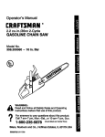
Operator's
Manual
Model No.
358.798470
CUSTOMER
ASSISTANCE
1-800-235-5878
Always
Wear Eye Protection
®
cc/2.0 cu. in. 2-CYCLE ENGINE
18 Inch Semi-Automatic Head®
GAS BRUSHWACKER ®
DANGER:
READ THE OPERATOR'S
MANUAL AND FOLLOW
ALL WARNINGS AND
SAFETY INSTRUCTIONS.
FAILURE TO DO SO CAN
RESULT IN SERIOUS
INJURY.
• Assembly
° Operation
• Customer Responsibilities
° Service and Adjustments
° Repair Parts
Sears, Roebuck and Co., Hoffman Estates, IL 60179 U_S.A.
530.083376-1-04/04/95
ii
i
tIJL
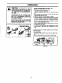
SAFETY RULES
cAUT|oNI ........
ALWAYS DI SCONNECT SPARK PLUG WlRE A ND PLACE WIRE WHERE IT CANNOT
CONTACT SPARK PLUG TO PREVENTACCIDENTAL STARTING WHEN SETTING UP, TRANSPORTING,
ADJUSTING OR MAKING REPAIRS.
OPERATOR
SAFETY
• Always wear safetyeye protection,
• Always wear long pants, tong sleeves, bootsand
gloves.Wearing safety leg guards is recommended. Do not go barefoot or wear sandals,
short pants, shortsleeves. Being fully covered
heJpsto protectyou from pieces cf toxic plants
thrown by the blade or cutting head.
• Secure hair so it is above shoulderlength. Secure
loose clothing or jewelry, or clothingwith loosely
hanging ties, straps,tassels,etc.;they can be
caught in moving parts.
• Do not operate this unit when you are tired, it!,or
under the influenceof alcohol, drugs,or medication.
• Wear hearing protectionif you use this unitfor
more than 1-1/2 hours per day.
• Never start or run the engine insidea closed
room or building. Breathing exhaustfumes can
kill.
• Keep handles free of oil and fuel
• Always use the handlebar and a properlyadjusted
shoulderharness.
• If situationsoccurwhich are not coveredin this
manual, use care and good judgement.
UNIT MAINTENANCE/SAFETY
• Look for and replacedamaged or looseparts before each use. Lookfor and repairfue! leaks before use. Keep the unit in good workingcondilion.
° Throw away bladesthat are bent,warped,
cracked, broken,or damaged in any otherway.
• Replace trimmer head parts that are chipped,
cracked, broken,or damaged in any otherway
before using the unit.
° Use only .080" diameter monofilamentline.
Never use wire, rope, string, etc.
• Keep the blade sharp and the cuttinglineat the
proper length.
• Make sure the unitis maintainedand assembled
correctlyas listedin this manual.
• Install the requiredshield properlybefore using
the unit. Use the metal blade shieldfor blades_
and the plastic linetrimmer shieldfor linetrimmer
use.
• Use only the specified blade or trimmerhead.
• Be sure blade or trimmer head stops turning
when engine idles,
• Make carburetoradjustments with the lowerend
supported to preventthe blade or trimmerline
from contactingany object. Hold unitby hand;do
not use shoulder harness for support.
• Keep othersaway when makingcarburetoradjustments.
I
•
•
Use only good quality SEARS accessories and
replacement parts as recommended for this unit.
Have air maintenance and service not explained
in this manual performed by your SEARS Service
Center.
FUEL SAFETY
•
•
•
•
•
•
•
Mix and pour fue! outdoors.
Keep away from sparks or flames.
Use a containerapproved for fuel.
Do not smoke or allow smoking near fuel or the
unit or while using the unit.
Wipe up all fuel spillsbefore starting engine.
Move at least 10 feet (3 meters) away from fueling site before starling engine.
Stop engine and allow the engine to cool before
removingfuel cap.
CUTTING SAFETY
•
•
•
•
•
•
•
•
•
•
Inspect the area to be cut before each use. Remove objects (rocks,broken glass, nails, wire,
string, etc.) which can be thrown or become entangled in the blade or tdmmer head.
Keep others includingchildren, animals, bystanders and helpers at least 50 feet (15 meters) away.
Stop the engine immediately if you are
approached.
Always keep the engine on the right-hand side of
your body.
Hold the unitfirmly with both hands.
Keep firm footing and balance. Do not overreach.
Keep the blade or trimmer head below waist level.
Do not raise the engine above your waist.
Keep all parts of your body away from the blade
or trimmerhead and muffler when engine is running.
Cut from your right to your left.
Use only for jobs explained in this manual.
TRANSPORTING
AND STORAGE
°
•
Stop the unitbefore transporting.
Allow the engine to cool, and secure the unit before storingor transportingin a vehicle.
• Empty the fuel tank before storingor transporting
the unit. Use up any fuel left in the carburetor by
starting the engine and letting the engine run until
it stops.
• Store unit and fuel in an area where fuel vapors
cannot reach sparks or open flames from water
heaters, electric motors or switches,furnaces,
etc.
• Store unit so the blade or line fimiter cannot accidentally cause injury.
• Store the unitout of the reach of children.
SAFETY'NOTICE
.
.............
J Exposure to vibrations through prolonged use of gasoline powered hand toots could cause blood vessel or nerve damage in the
I fingers, hands, and joints of people prone to circulation disorders or abnormal swel|ings. Prolonged use in cold weather haS been
| linked to blood vessel damage in otherwise healthy people. If symptoms occur such as numbness, pain, loss of strength, change
] in skin color or texture, or loss of feeling in the fingers, hands or joints, discontinue the use of this unit and seek medical a_enItton. An anti-vibration system does not guarantee the avoidance of these problems. Users who operate power tools on a continuI al and regular basis must monitor closely their physical condition and the condition of this unit.
IT
MEANS
AI"FENTIONtll
BECOME
YOUR SAFETY
INVOLVED.
LOOK
FOR - THIS
SYMBOL TO
POINT ALERTllf
OUT IMPORTANT
SAFETYIS PRECAUTIONS.
"2-
I
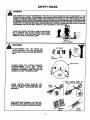
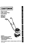
SAFETY RULES
DANGER
THIS POWER UNIT CAN BE DANGEROUS! THIS UNIT CAN CAUSE SERIOUS INJURY OR BLINDNESS TO THE
OPERATOR AND OTHERS, THE WARNINGS AND SAFETY INSTRUCTIONS IN THIS MANUAL MUST BE FOLLOWED TO PROVIDE REASONABLE SAFETY AND EFFICIENCY IN USING THIS UNIT. THE OPERATOR IS RESPONSIBLE FOR FOLLOWING THE WARNINGS AND INSTRUCTIONS IN THISMANUALAND ON THE UNIT.READ
THE ENTIRE OPERATOR'S MANUAL BEFORE ASSEMBLING AND USING THISUNIT! RESTRICT THE USE OF THIS
POWER UNIT TO PERSONS WHO READ, UNDERSTAND AND FOLLOW THE WARNINGSAND INSTRUCTIONS IN
THIS MANUAL AND ON THE UNIT. NEVER ALLOW CHILDREN TO USE THIS TOOL.
BLADE CAN THRUST VIOLENTLY AWAY FROM MATERIAL IT CANNOT CUT. BLADE THRUST CAN CAUSE
AMPUTATION OF ARMS OR LEGS. KEEP PEOPLE AND
ANIMALS 50 FEET (15 METERS) AWAY.
BLADE THRUST
WARNING
Leg Guards
BLADE/TRIMMER
LINE CAN THROW OBJECTS VIOLENTLY. YOU CAN BE BLINDED
OR INJURED. WEAR EYE AND LEG PROTECTION.
Eye
Protection
Thrown
Boots
ird Zone
HAZARD ZONE FOR THROWN OBJECTS.
BLADE/TRIMMER
LINE
CAN
THROW
OBJECTS VIOLENTLY. OTHERS CAN BE
BLINDED OR INJURED, KEEP PEOPLE AND
ANIMALS 50 FEET (15 METERS) AWAY.
Stop Coasting Blade By
ContactWith Cut Material.
BLADE COASTS AFTER THROTTLE RELEASE. THE BLADE CAN SERIOUSLY CUT
YOU OR OTHERS. STOP BLADE WITH CUT
MATERIAL.
Blade
Coasts
READ OPERATOR'S MANUAL. FOLLOW ALL
WARNINGS AND INSTRUCTIONS. FAILURE
TO DO SO CAN RESULT IN SERIOUS INJURY.
Manual
Safety
Labels
ill
-3-
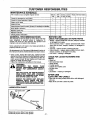
PRODUCT
SPECIFICATIONS
,, ,,, ,,,,
CONGRATULATIONS
on your purchase of a Sears
Craftsman
Brushwacker.
It has been designed,
engineered and manufactured to give you the best
possible dependability and performance.
CUTTING PATH
Trimmer Head ................... 18"
Weed Blade ........ _............. 8"
Brush Blade ...................... 8"
Should you experience any problems you cannot easily
remedy, please contact your nearest Sears Service
Center/Department. Sears has competent, well trained
technicians and the proper tools to service or repair this
unil.
TRIMMER LINE ................... 080" Diameter
Monofilament Line
Please read and retain this manual. The instructions will
enable you to assemble and maintain your unit property.
Always observe the "SAFETY RULES."
MODEL NUMBER:
358.798470
HEAD ROTATION ............... Counterclockwise
(foroperator)
ENGINE .............................. 32 cc, 2-cycle Air-Cooled
FUEL/OIL MIX RATIO ......... 40:1 (3.2 oz. oil per
gallon gas)
iGNITION ............................ Solid State
IGNITION TIMING .............. Non-adjustable fixed
SPARK PLUG TYPE ........... Champion (RCJ-8Y)
SPARK PLUG GAP ............. 025" (.6mm)
DATE CODE/SERIAL NO.:
MUFFLER ........................... Temperature Limiting
(not spark arresting)
DATE OF PURCHASE:
ENGINE RPM ..................... Operating - 9000 Max.
THE MODEL AND SERIAL
FOUND ON THE PRODUCT.
NUMBER WILL BE
YOU SHOULD RECORD BOTH SERIAL NUMBER
AND DATE OF PURCHASE AND KEEP IN A SAFE
PLACE FOR FUTURE REFERENCE.
MAINTENANCE
AGREEMENT
A Sears Maintenance Agreement is available on this
product. Contact your nearest Sears Store for detaiIs.
CUSTOMER
RESPONSIBILITIES
• Read and observe the safety rules.
• Follow a regular schedule in maintaining, caring for,
and using your unit.
• Follow the instructionsunder"Customer Responsibilities"
and "Storage" sectionsof this Operator's Manual.
SPECIAL NOTICE
For userson U.S.ForestLandand in somestates,including
California (Public ResourcesCodes 442 and 443), Idaho,
Maine, Minnesota,New Jersey,Oregon,and Washington:
Certain internalcombustionengines operatedon forest,
brush, and/or grass-covered lands in the aboveareas are
required to be equipped witha spark arrestor,
maintainedin
effectiveworkingorder,or Ihe enginemustbe constructed,
equipped, and maintainedfor the prevention of fire.Check
withyourstate or localauthoritiesfor regulations
pertaining
tothese requirements. Failuretofollowtheserequirements is
a violationofthe taw.This unitisnot factory=equipped witha
sparkarrestor;however,a sparkarrestoris availableas an
optionalpart.ff a sparkarrestoris requiredin yourarea,contact yourSEARS ServiceCentedDepartment
for thecorrect
kit.
Manufactured under one or more _f the following U,S, patet_ls: 5,_,427:
5.367,988:
5,345.684; 5,343_831; 5.276.968: 5,269.665; 5.G_0,L_23: 4,940,028: 4,697,923: 4,852,258:
4,846,123; 4,84 t,929; 4.835,867; 4,825.548; 4,823,465; 4,819,742; 4,798,185: 4,508,068;
4,483,069; 4,451,983: 4,366,622:4.366.62114.352,243;
4,347,666: 4,L_0,200; 4.286,675;
4,236.312; 4,177,_61 ; 4,172.322; 4.167,812; 4,!62,575;
4,161,820; 4,122.653: 4,104,797:
Re,32.266; D344,088; D324.051: 1_304.196; 0276,!60.
Other U,S. and foreign patents
periling.
FULL ONE YEAR WARRANTY ON CRAFTSMAN GAS-POWERED
BRUSHWACKER e BLADED TRIMMER
For one year from the date of purchase, when this Craftsman Gas-Powered Brushwacker_ is maintained, lubricated
and tuned up according to the operating and maintenance instructions in the Operator's Manual, Sears will repair, free
of charge, any defect in materials or workmanship.
This warranty excludes the blade, nylon line, spark plug, and air filter, which are expendable parts and become worn
during normal use.
If this Brushwacke_' is used for commercialpurposes, this warrantyapplies for only 90 days from the date of pumhase.
If this Brushwacket _ is used for rental purposes, this warranty applies for only 30 days from date of purchase.This warrant',/applies only while this product is in use in the United States.
WARRANTY SERVICE IS AVAILABLE BY RETURNING THE BRUSHWACKEFP TO THE NEAREST SEARS SERVICE CENTER IN THE UNITED STATES.
This warranty gives you specificlegal rights, and you may also have other rights which vary from state to state.
SEARS, ROEBUCK AND CO., D/817WA, HOFFMAN ESTATES, IL 60179
,,
-4-
, ,, ,,,,,,, ,,,
i
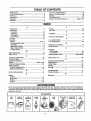
TABLE OF CONTENTS
Safety Rules ....................................................................
2
Product Specifications ................ :..................................... 4
Warranty ..........................................................................
4
Accessories .....................................................................
5
Assembly .........................................................................
7
Operation ......................................................................
12
Customer Responsibilities ............................................. 21
Service and Adjustments .............................................. 24
Storage.......................................................................... 30
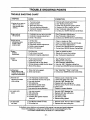
Trouble Shooting ........................................................... 31
Repair Parts Ordering/Service ....................... Back Cover
INDEX
A
Accessories...,,................................................................ 5
Adjustments
Carburetor .................................................................. 29
Handlebar .................................................................. 17
Idle Speed ....................................... ........................... 29
Line Advance ............................................................. 17
Air Filter ......................................................................... 22
Assembly
Blades ............................................................... 10 & 11
Semi-automatic Head .................................................. 9
Handlebar .................................................................... 8
Metal Debris Shield ................................................... 10
Plastic Debris Shield .................................................... 8
Throttle Handle ............................................................ 9
B
Blade Sharpening ......................................................... 28
Blade Thrust .................................................................. 14
C
Carburetor Adjustments ................................................ 29
Carton Contents .............................................................. 6
Customer Assistance
Hotline................................. ;........................... Back Cover
Customer Responsibilities ............................................. 21
Cutting Methods
Trimmer Operating Tips ............................................. 20
Blade Operating Tips ................................................. 15
D
Drive Shaft Lubrication .................................................. 22
E
Engine
Fuel/Oil....................................................................... 18
Spark Plug ................................................................... 4
Starting ...................................................................... t 9
Storage ...................................................................... 30
F
Fue!ing .......................................................................... 18
Fue! Filter ...................................................................... 23
H
Handlebar .............................................................. _........:8
K
Know Your Brushwacker ................................................ 12
L
Line Advancement ........................................................ 17
Line Replacement ......................................................... 26
M
Maintenance Schedule ....i ............................................ 21
Model Number. ...... .......................................................... 4
O
Operation
Brushwacker .............................................................. 18
Line Trimmer .............................................................. 20
Ordering Repair Parts .................................... Back Cover
R
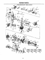
Repair Parts List ........................................................... 32
S
Service and Adjustments.............................................. 24
Specifications.................................................................. 4
Starter Rope .................................................................. 24
Starting.......................................................................... 19
Storage.......................................................................... 30
T
Throttle Handle ................................................................ 9
Trouble Shooting .......................................................... 31
W
Warranty .......................................................................... 4
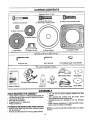
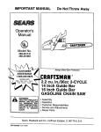
ACCESSORIES
These accessories and attachments' Were available when the unit was originally purchased.They are also available at
mostSears retail outletsand service centers. Most Sears storescan order these items for you when you providethe model
number of your unit.
Accessories
,,,,,,,,,,,,,,,
GAS
CAN
,,,
SAFETY
GOGGLES
2-CYCLE
ENGINE
OIL
_ ,,,i
,
SPARK
SEMI-
PLUG
AUTOMATIC
HEAD
BULK
LINE
3.2 OZ.
40:1
400 FT.
-5-
SPOOL WITH
LINE
SHOULDER
STRAP KIT
AIR
FILTER
CARTON CONTENTS
Hardware shown full size
(2) Nose Cone Screws
(2) Handle Bar Screws
(4) Metal Debris Shield Screws
(4) Plastic Debris Shield Screws
@
(2) Nose Cone Nuts
(1) BeveledWasher
(1) Flat Washer
(1) Flange Hex Nut
(1) Grass Washer
(1) Retention Plate
Parts bag contents not shown full size
Long Hex Key
(1) Handlebar Upper Cover Bracket
Short Hex Key
Parts packed separately in carton
;-il...........
!
Metat Debris Shield
Shoulder Strap w/Warning
Operator'sManua_
_
Semi-i_Uta_dmatic
Plastic Debris Shield
Engine Oil
Weed Blade
(D
Brush Blade
ASSEMBLY
TOOLS REQUIRED
FOR ASSEMBLY
• Torque wrench (optional) - Referencetorquevalues are
providedthroughoutthis manual for tighteninghardware,
• Long hex key (included)
• Short hex key (included)
• Adjustablewrench or large pliers
• Phillips screwdriver
TO REMOVE BRUSHWACKER
FROM CARTON
• Remove loose parts bag and carton contents included
with Brushwacker _
• Remove your BrushwackeP from the packingmaterial.
-6-
• You may use the opened packing material as a work
surface
° After removing the contents from the carton, check
parts against the carton contents list
• Examine the parts for damage Do not use damaged
parts
• Notify Customer Assistance at 1-800-235-5878 immediately ff a part is missing or damaged
NOTE: It is normal to hear the fuel filter rattle in an empty
fuel tank.
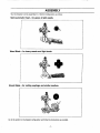
ASSEMBLY
Your brushwacker
Semi-automatic
Weed
can be assembled
in 3 distinct
Head - for grass
Blade - for heavy
weeds
configurations
& light
as follows:
weeds,
and light brush.
Brush Blade - for cutting saplings
and similar medium.
Go to the section for the desired configuration and follow the instructionsas provided.
-7-
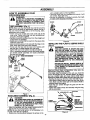
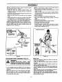
ASSEMBLY
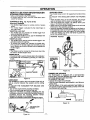
HOW TO ASSEMBLE
BRUSHWACKER
_
'fOUR"
short, straight section of the handlebar.
° Place the cover over the handlebar and secure it with
twoscrews, finger tight only.
• Be sure the handlebar is installed correctly, then tighten each screw securely and evenly.
IF THIS
UNIT IS RECEIVED ASSEMBLED,
ARNING:
REVIEW ALL STEPS IN THIS SECTION TO
BE SURE ASSEMBLY IS CORRECT AND
PROPERLY ADJUSTED FOR THE OPERATOR,
ENGINE
SCREW
TUBE ASSEMBLY
(Fig. I)
NOTE: Make sure the drive shaft does not fall out of the
tube. Dirt on the shaft will significantly reduce the life of
the unit. !f the drive shaft fails out of the housing, clean,
relubricate, and re-instalL
• Insert nose cone screws and nose cone nuts in the
nose cone. Tighten with long hex key (provided) just
enough to hold parts together.
• Remove the plastic packing cover from the straightend
of the tube if so equipped.
• Slightly pull out drive shaft to insert into the square hole
inside the nose cone.
• Align the bottom groove in the tube with the ridge on the
inner, lower wall of the nose cone opening.
• Firmly push the tube into the nose cone opening until
the foam grip is seated against the nose cone.
• Tighten the nose cone screws securely and evenly.
• Prior to handlebar assembly, ensure that cable harness
and throttle handle assembly are routed underneath
the tube and foam grip,
FOAM
HANDLEBAR
GRIP
COVER
Figure 2
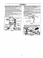
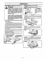
INSTALLING THE PLASTIC
THE
LINE LIMITER IS SHARP AND CAN
ARNING:
CUT YOU. BE SURE TO WEAR GLOVES
WHILE WORKING WITH THE LINE LIMtTER.
_
THE DEBRIS SHIELD MUST BE PROPERLY INSTALLED FOR ALL LINE TRIMMER
USAGE. DEBRIS SHIELD PROVIDES PARTIAL PROTECTION FROM THE RISK OF
THROWN OBJECTS TO THE OPERATOR
AND OTHERS.
NOSE CONE SCREWS
DRIVE
j
NOSE
CONE
SHAFT
FAILURE TO INSTALL DEBRIS SHIELD IN
THE POSITION SHOWN IN FIGURES 3 AND
4 CAN RESULT IN SERIOUS INJURY TO
THE OPERATOR.
NOSE
CONE
NUTS
Weed and Brush Blade configurations follow after this
Weedwacker configurationsection.
If the metal shield is installed on the unit, you must first
remove the flan_ed hex nut, beveled washer, flat washer,
dust cup, retenbon plate and metal debris shield before
installing the plastic debris shield and semi-automatic head.
o Remove the dust cup from the arbor shaft (ref. Fig. 3).
• Place debris shield under the gear box and align screw
holes. Make sure the widest part of the debris shield is
pointing toward the engine.
• Insert the four screws through the gear box into the
debris shield.
° Tighten the screws evenly and securely using the long
hex key (provided).
FOAM GRIP
r-
Figure 1
HANDLEBAR
i_
DEBRIS SHIELD
ASSEMBLY
ENGINE
(Fig. 2)
THE
HANDLEBAR MUST BE ASSEMBLED
DANGER:
CORRECTLY IN THE MOUNTING BRACKET SO THE HANDLEBAR IS A BARRIER
TO KEEP THE OPERATOR'S FEET FROM
BEING CUT BYTHE BLADE.
Align the handlebar with the straight barrier portion to
the left and the curved portion to the right.
NOTE: Be sure the barrier portion of the handlebar is to
the left of the tube (for operator).
, Position the mounting block between the arrows on the
DUST CUP
(MUST BE
REMOVED FOR
PLASTIC
DEBRISSHIELD
"_
DEBRIS SHIELD
INSTALLATION)
ARBOR SHAFT
Figure 3
-8-
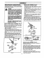
ASSEMBLY
SEMI-AUTOMATIC
HEAD ASSEMBLY
(Fig. 4)
• Ensure the plasticdebrisshield is in place and secured.
• Install dust cup over the arbor shaft.
• Align the hole in the dust cup with the hole in the center front of the gear box by turning the dust cup.
• Install the grass washer over the arbor shaft. Make sure
the grass washer is against and curved over the dust cup.
• Start threading the semi-automatic head onto the arbor
shaft (counterclockwise).
• Insert the short hex key (provided) into the aligned
holes to keep the arbor shaft from turning.
• Tighten the semi-automatic head while holding the
short hex key.
• Remove the short hex key.
THROTTLE
HANDLE
ASSEMBLY
(Fig. 5 & 6)
• Remove the screw from the throttle handle.
• Slide the throttle handle onto the right side of the handlebar and align the screw hole.
• Placing the engine on your right side, with the shaft of
the unit extending to the front, the throttle handle
should be in your right hand,
IMPORTANT: REFER TO THE ILLUSTRATION ON THE
FRONT COVER FOR PROPER POSITION. MAKE
SURE THE ENGINE SWITCH IS LOCATED ON THE
TOP OF THE HANDLEBAR.
• Insert screw and tighten with hex key.
ENGINE SWITCH
THROT'rLE
SCREW
GEARBOX
THROTTLE
WIDEST PART
OF SHIELD
THRO'FrLE TRIGGER
Figure 5
• After attaching the throttle handle assembly and handlebar to the unit, rout the cable harness assembly
through the slit in the bottom of the foam grip.
FOAM
GRIP
ABLE HARNESS AND
HANDLE ASSEMBLY
Figure 6
-9-
ASSEMBLY
I
BRUSHWACKER
I
ii ii
iii
CONFIGURATION
Assembly information for Weedwacker configuration is
located before this section, the Brush Blade configuration follows after this section.
DANGER:
THE METAL SHIELD MUST BE PROPERLY
INSTALLED ON THE TOOL ANYTIME THE
TOOL IS USED WITH THE BLADE. THE
FORWARD TIP ON THE METAL SHIELD
HELPS TO REDUCE THE OCCURRENCEOF
BLADE THRUST WHICH CAN CAUSE
SERIOUS INJURY SUCH AS AMPUTATION
TO THEOPERATORORBYSTANDERS.
FAILURE TO INSTALL THE DEBRIS SHIELD
IN THE POSITION SHOWN CAN RESULT IN
SERIOUS INJURY TO THE OPERATOR. THE
LENGTH OF THE DEBRIS SHIELD MUST BE
ALIGNEDWRH THE LENGTHOF THE DRIVE
SHAFT HOUSING.
THE BLADE IS SHARP AND CAN CUT YOU.
BE SURE TO WEAR GLOVES WHILE
WORKING WITH BLADES
METAL DEBRIS SHIELD ASSEMBLY
i
iiii IIIH
WEED BLADE ASSEMBLY
(Fig. 8)
• Install the dust cup over the arbor shaft.
• Install blade over arbor shaft, making sure the hole in
the center of the blade is fitted around the raised center on the dust cup.
• Install the large flat washer, beveled washer and
flanged hex nut as shown. Be sure beveled washer is
installed as shown in Figure 8 (inset).
• Align hole in the dust cup with the hole in the side of the
gear box by turningthe dust cup.
• insert the short hex key (provided) into the aligned
holes.
• While holding the short hex key in position, firmly tighten flanged hex nut counterclockwisewith a wrench.
• Remove the short hex key.
• Turn blade by hand. ft the blade binds against the metal
debris shield, blade is not centered. Reinstall blade.
NOTE: To remove the blade, align holes as in step
above; then, insert the short hex key. Unthread hex flange
nut and remove parts. Be sure to store the blade, flat
washer, cupped washer, and hex flange nutfor future use.
(Fig. 7)
NOTE: If your unitis equipped as a line trimmer, remove
the semi-automatic head, grass washer, and plastic
debris shield. Store parts for future use.
• Remove and discard the packing cover from the arbor
shaft, if so equipped_
• Remove the dustcup. Save for later use.
• Position the retention plate on the underside of the
metal debris shield and align screw holes. Make sure
the flat side of the plate is against the metal debris
shield.
• Hold the retention plate in positionand place the metal
debris shield underthe gear box. Alignscrew holes.
• Insert the four metal debds shield screwsone at a time
through the gear box and debris shield, then thread
them intothe retentionplate,
• Tighten the debris shield screws evenly and securely
with the long hex key (provided),
T CUP
_..
_
%LARGE
FLAT
__
BLADE
_ _4_I"WASHER
_1- BEVELED
NUT--
_
Ji
_
i,J
,
(_";)
_
.
WASHER
L,.
LI
CUPPED SIDE
TOWARD
BEVELED
HEX
_'q_
SCREW
SHORT HEX KEY
KEY
Figure 8
BRUSH BLADE ASSEMBLY
(Fig. 9)
Assembly information for Weedwacker configuration is
located before this section.
GEAR
_I_'_DUST
i
I
METAL
SHIELD
CUP
I _-*" ARBOR
SHAFT
If plastic debris shield is installed on the unit, you must
first remove the semi-automatic head and plastic debris
shield before installing metal debris shield and blade. If
you have already configured your unit for weed blade
use, you have already installed the metal shield and
should remove the weed blade.
_
• Install the dust cup over the arbor shaft.
, Install blade over arbor shaft, making sure the hole in
the center of the blade is fitted around the raised
center on the dust cup.
RETENTION
PLATE
Figure 7
-10-
ASSEMBLY
NOTE: If installing brush blade, make sure teeth on blade
are oriented as shownin Figure 9.
• Instal_ the large flat washer, beveled washer and
flanged hex nut. Be sure beveled washer is instaiJed as
in Figure 9 (inset).
• Aiign hole in the dust cup with the hole in the side of the
gear box by turning the nut.
° Insert the short hex key (provided) into the aligned
holes,
• While holding the short hex key in position,firmIy tighten flanged hex nut counterclockwise with a wrench.
° Turn blade by hand. If the blade binds against metal
debris shield, blade is not centered. Reinstall blade.
NOTE: To remove the blade, reverse installation steps.
Unthread flanged hex nut and remove parts. Be sure to
store the blade, large flat washer, beveled washer and
flanged hex nut for future use,
NOTE: A one-half twist is built in the shoulder strap to
allow the strap to rest flat on the shoulder.
° Adjust the strap so that the hook wilt be about 6 inches
below the waist.
• Fasten shoulder strap hook to clamp located between
the foam grip and mounting block and lift tool to the
operating position.
Check the following:
• Left arm extended, hand holding handlebar grip.
• Right hand holding trigger handle, fingers on throttle
trigger.
• Engine below waist tevel.
• Shoulder strap pad centered on left shoulder.
• Danger sign centered on your back.
• Full weight of tool on left shoulder.
• Without operator bending over, the blade or semiautomatic head is near and parallel to the ground and
easily contacts material to be cut.
OPERATING POSITroN
HEX WRENCH IN
ALIGNED HOLES
VASHER
DANGER SIGN
CENTERED ON
YOUR BACK
WASHER
DECALON
CLAMP
NUT _CUPPED SIDE
TOWARD
==1An=
_ BEVELED
ii
i
Figure 10
Figure 9
SHOULDER
I_
STRAP
ASSEMBLY
(Fig. 10)
PROPER
SHOULDER
STRAP AND 1
HANDLEBAR
ADJUSTMENTS
BEFORE !J
WARNING:
STARTING THE ENGINE ARE REQUIRED J
• Try on shoulder strap and adjust for fit and balance
before starting the engine and beginning a cutting
operation.
• Insert your right arm and head through the shoulder
strap and allow it to rest on your left shoulder. Make
sure the danger sign is on your back and the hook is
to the right side of your waist.
-11-
CHECK LIST
• Check all fasteners. Make sure they are tight and
there are no loose pads.
• Check to make sure the throttle cable is positioned
correctly.
° Check the blade. Make sure the blade is secure and
will not move from side to side.
° Turn the blade by hand. if the blade binds against the
shield or wobbles, the blade is not centered. Reinstall
the blade.
° Make sure the long arm of the handlebar extends to
the left of the tube and in front of the operator.
• With the unit held in the operating position, adjust the
assist handle up or down the tube for best comfort and
balance before first use.
ii ii
.||11
i
i
ii
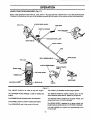
OPERATION
KNOW
YOUR
BRUSHWACKER
(Fig. 11)
READ THIS OPERATIONS MANUAL AND SAFETY RULES BEFORE OPERATING YOUR BRUSHWACKER.
Compare the illustrationswith your unit to familiarize yourself with the location of the various controls and adjustments.
STARTER ROPE HANDLE
FUEL CAP
/
HANDLEBAR
THROTrLE TRIGGER
/
; SHOULO
ON/OFF SWITCH
SAFETY LABELS
TUBE
/
BRUSH BLADE
FUEL CAP
PLASTIC DEBRIS SHIELD
\
SEM!*AUTOMATIC
CHOKE LEVER
COVER
_@_AD!
WEED BLADE
LINE
LIMITER
MUFFLER & GU_D
IIIIIIIIIIIII
I IIII
IIIIII IIIIIIII
II
IIIIIII
II
IIIIIIIIIIIIIIII
II
Figure 1t
The ON/OFF SWITCH
is used to slop the engine.
The THRO'I-FLE TRIGGER controlsengine speed..
The STARTER ROPE HANDLE is used for startingthe
engine.
The SEMI-AUTOMATIC HEAD contains spool of line
which advanceswhen head is tapped on the ground.
The PRIMER BULB circulates fuel to the carburetor.
The WEED BLADE is designed to cut grass, weeds, and
woody brush up to !/2 inch in diameter.
The CHOKE LEVER is used for startingcold engine.
The BRUSH BLADE is designedto cut grass, weed, and
woodybrushand smalltreesup to 2 t/2 inchesin diameter.
The HANDLEBAR aids in the controlof the unit.
The LINE LIMITER cuts trimmer fine automatically to the
correct length.
-t2-
r
mlJ,_L
=======
,,
,,, ,,,,
== =
OPERATION SAFETY
BLADE
SAFETY
WARNING
THROWN
OBJECTS
Leg Guards
-THE RAPIDLY MOVING
BLADE CAUSES OBJECTS TO BE THROWN VIOLENTLY. _;_
THE SHIELD WILL NOT PROVIDE COMPLETE PROTECTION TO THE OPERATOR OR OTHERS. THE OPERATOR
MUST WEAR A SAFETY FACE SHIELD OR GOGGLES.
ALWAYS WEAR SAFETY LEG GUARDS AND BOOTS. Face
KEEP OTHERS AT LEAST 50 FEET (15 METERS) AWAY.
Shield
HAZARD ZONE - THIS UNIT WILL THROW OBJECTS
AND CUT. KEEP OTHERS INCLUDING CHILDREN, ANIMALS, BYSTANDERS, AND HELPERS AT LEAST 50 FEET
(15 METERS) AWAY FROM THE OPERATOR AND UNIT.
STOPTHE ENGINE AND BLADE IMMEDIATELY IFYOU ARE
APPROACHED. IN AREAS WHERE OTHER PEOPLE AND
ANIMALS ARE PRESENT, SUCH AS NEAR SIDEWALKS,
STREETS, HOUSES, ETC., IT IS STRONGLY RECOMMENDEDTHATTHE OPERATOR USETHE BUDDY SYSTEM;THAT
IS, HAVE ANOTHER PERSON SERVE AS A "LOOK OUT,"
KEEPING HIMSELF AND OTHERS AT LEAST 50 FEET (15
METERS) AWAYFROM THE OPERATOR.
COASTING
OPERATOR
•
•
•
•
°
•
•
•
SAFETY
•
Zone
Coasts
Blade
•
Alwayswear eye protectionwhen operating,servicing,or
performing maintenance on your unit. Refer to
"Accessories:'
Alwayswear long pants,long sleeves,bootsand gloves.
Wearing safety leg guards is recommended.Do not go
barefoot or wear sandals, short pants, short sleeves.
Being fully covered helpsto protect you from pieces of
toxic plantsthrownby the blade or cuttinghead.
Secure hair so it is above shoulder length.Secureloose
clothing or jewelry,or clothingwith loosely hangingties,
straps,tassels,etc.;they can be caughtin movingparts.
Do not operate this unitwhen you are tired, ill, or under
the influenceof alcohol,drugs, or medication.
Always use the handlebar and a properly adjusted
shoulder strap. Refer to "Assembly" and "Operation".
Do not swing the unit with such force that you are in
danger of losing your balance.
Never start or run the engine inside a closedroom or
building. Breathingexhaust fumes can kill.
Keep handles free of oil and fuel,
UNIT SAFETY
°
Hazard
Stop Coasting Blade by
Contact with Cut material.
BLADE - THE BLADE CONTINUES TO
SPIN AFTER THE ENGINE IS STOPPED OR THE
THROTTLE IS RELEASED. THE COASTING BLADE
CAN THRUST, THROW OBJECTS, OR SERIOUSLY
CUT YOU IF ACCIDENTALLY TOUCHED. STOP THE
BLADE BY LEAVING IT IN CONTACT WITH MATERIAL
ALREADY CUT. USE THE "9 O'CLOCK" POSITION AS
THE POINT OF CONTACT.
Boots
Inspect the entire unit before each use. Replace
damaged parts. Check for fuel leaks and make sure all
handles, guards,and fasteners are in placeand secure.
Be sure the metat bladeshield isproperlyattached. The
metal blade shield mustbe installedfor all bladeusage.
Make sure the blade is properlyinstalled and securely
fastened. Refer to "Assembly."
, Be sure the blade stops turningwhen the engine idles.
Refer to'Trouble Shooting Chart."
* Make carburetor adjustments with the drive shaft
housingsupportedto preventthe blade from contacting
any object.
• Hold unit by hand; do not use harness for support.
• Keep others away when making carburetor
adjustments.
• Have all maintenance and service not explained in this
manual performed by a Sears Service Center.
• Use only Sears bladesand accessories.
CUI"I'ING
•
.
.
•
•
•
.
•
-13-
SAFETY
Inspect the area to be cut before each use. Remove
objects (rocks, broken glass, nails, wire, string, etc.)
which can be thrownor become entangled in the blade.
Always keep the engine on the right side of your body,
Hold the unitfirmlywilh both hands,
Keep firm footing and balance. Do not over-reach.
Keep blade below waist level.
Do not raise the engineabove your waist. The blade can
come dangerouslyclose to your body.
Cut at full throttle,
Cut from your rightto your left.
Use only for jobs explained in this manual. Do not use
the blade as an edger. The shield does not provide
adequate protection.
i
,,i
,,,,i
i,lul,ii
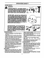
OPERATION SAFETY
BLADE
.................................
SAFETY
DANGER
THIS
POWER UNIT CAN BE DANGEROUS! THIS UNIT CAN CAUSE SERIOUS INJURY OR BLINDNESS
TO THE OPERATOR AND OTHERS. THE WARNINGS AND SAFETY INSTRUCTIONS IN THIS MANUAL
MUST BE FOLLOWED TO PROVIDE REASONABLE SAFETY AND EFFICIENCY IN USING THIS UNIT.
THE OPERATOR IS RESPONSIBLE FOR FOLLOWING THE WARNINGS AND INSTRUCTIONS IN THIS
MANUAL AND ON THE UNIT,,READ THE ENTIRE OPERATOR S MANUAL BEFORE ASSEMBLING AND
USING THIS UNIT! RESTRICT THE USE OF THIS POWER UNIT TO PERSONS WHO READ, UNDERSTAND AND FOLLOW THE WARNINGS AND INSTRUCTIONS IN THIS MANUAL AND ON THE UNIT.
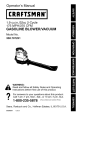
BLADE THRUST- WHEN THE SPINNING BLADE CONTACTS
ANYTHING IT CANNOT CUT, A DANGEROUS REACTION MAY
OCCUR CAUSING THE ENTIRE UNIT AND OPERATOR TO BE
THRUST VIOLENTLY IN ANY DIRECTION. THIS REACTION IS
CALLED BLADE THRUST. AS A RESULT, THE OPERATOR CAN
LOSE CONTROL OF THE UNIT. USE HANDLEBAR, SHOULDER
HARNESS, AND KEEP METAL BLADE SHIELD IN PLACE, MAKE
SURE OTHERS ARE AT LEAST 50 FEET (15 METERS) AWAY.
KEEP BLADE SHARP. CUT AT FULL THROTTLE AND FROM
YOUR RIGHT TO LEFt. KEEP HANDS, FEET AND UNIT IN PROPER POSITION; REFER TO "GUARD AGAINST BLADE THRUST,"
PROPER
BLADEUSE ONLY THE 8 °'BRUSH BLADE OR 8"
WEED BLADE AND PROPER HARDWARE AS SHOWN. THE
USE OF ANY OTHER PARTS CAN RESULT IN SERIOUS
INJURY. DO NOT USE ANY ACCESSORY OR ATTACHMENT
OTHER THAN THOSE RECOMMENDED BY THE MANUFACTURER FOR USE WITH THIS UNIT. BLADES THAT ARE BENT,
WARPED, CRACKED, BROKEN, OR DAMAGED CAN FLY
APART AND CAUSE SERIOUS INJURY, DO NOT USE; THROW
AWAY,
BLADE
THRUST
IS a reaction that only occurs
when using a bladed unit. This reaction can cause
serious injury such as amputation. Carefully study
this section. Itis importantthat you understandwhat
causes blade thrust,how you can reducethe chance
of it occurring, and how you can remain in controlof
the unit if blade thrustoccurs.
WHAT CAUSES BLADE
THRUST?
Blade Thrustcanoccurwhen thespinningbladecontacts an object that it does not cut. This contact
causes the bladeto stop for an instantand then suddenlymove or "thrust"away fromthe objectthatwas
hit.The "thrusting" reaction can be violentenough to
cause the operator to be propelled in any direction
and Josecontrolotthe unit. The uncontrolledunitcan
cause sedous injuryif the blade contacts the operator or others.
WHEN DOES BLADE THRUST OCCUR?
Blade thrust can occur without warning if the blade
snags, stalls, or binds. This ismore likelyto occurin
areas where it isdifficultto see the matedal beingcut.
By using the unit properly, the occurrenceof blade
thrustwill be reduced and the operator will be less
likelyto lose control.
The forward tip on the metal bladeshieldhelpsto reduce the occurrence of blade thrustbut cannot prevent the occurrence. The operator must follow all
warnings and safety instructionsin this manual to
lessen the chance of blade thrustoccurringand to
maintain controlof unit if the reactiondoes occur.
-14-
8" WEED BLADE
ARBOR
(20MM)
8" BRUSH BLADE
REDUCE THE CHANCE OF BLADE THRUST
•
Cut vegetation up to 2 1/2" diameter saplingswith
saw blade.
• Cut onlygrass,weeds, and woodybrushup to 1/2" in
diameterwiththebrushtri-blade. Donotletthe blade
contact materialitcannot cut suchas stumps,rocks,
fences, metal, etc., or clustersof hard, woodybrush
having a diameter greater than 2 1/2 inches.
• Keep the blade sharp. A dull blade is more likely to
snag and thrust.
• Cut onlyat fullthrottle. The blade has maximumcutting power at full throttleand is less likelyto bind or
stall.
• "Feed" the bladedeliberatelyandnottoo rapidly.The
blade can thrustaway if it is fed too rapidly.
• Cut onlyfrom yourright to your left.
ii irl ii
ii
:
i
iiiiiiiiiiii
iiiii
i
i|1
iii
iii
THE
BLADE CONTINUES
TO SPIN
WARNING:
AFTER THE ENGINE IS TURNED OFF.
THE COASTING BLADE CAN SERIOUSLY CUT YOU IF ACCIDENTALLY
TOUCHED.
THE OPERATOR OR OTHERS MUST
NOTTRY TO CLEAR AWAY CUT MATERIAL WITH THE ENGINE RUNNING OR
THE BLADETURNING.
STOP ENGINE AND BLADE BEFORE
REMOVING
MATERIALS
WRAPPED
AROUND THE BLADE SHAFT.
!
®
j
iii
OPERATION
Stop
Coasting
Blade
By
Contact
With Cut
Matarlal
imll
i
i
ii i
=
ii
ii
BLADE OPERATING
TIPS (Fig. 12)
To establisha rhythmiccutting procedure:
,, Plantfeetfirmly,comfortably
apart.
• Cutwhileswingingthe upperpartof yourbodyfrom rightto
left.
• Move forward to the next area to be cut after the return
swin.q
end plantfeet once more.
• Usethe8 o'clockto 10 o'clockpositionforcutting.
• Bring the engineto full throttlebeforeenteringthe maleriat
tobe cut. The bladehas maximumcuttingpowerat full throttie and is less likely to bind, stall, or causeblade thrust,
whichcan resultin seriousinjuryto the operatoror others.
Referto"GuardAgainstBladeThrust".
• Alwaysreleasethrottletdggerand allowengineto returnto
idlespeedwhennot cutting............
• Cutonlyfrom yourrightto yourloll, Swingingtheunit in the
same directionas the blade spinsincreasingthe cutting
action.
To reducethe chanceof mateda!wrappingaroundthe blade,
followthesesteps:
• Cutat furlthrottle.
• Swingthe unitinto materialtobe cut fromyourrightto your
left.
• Avoidthe materialjust cutas youmakethereturnswing.
,.,,4"
Direction to Cut
Cut Between
t
the 8 o'clock
and 10 o'clock
Position
=
Figure 12
-15-
i
iii
i
Ji
i
OPERATION SAFETY
i
i
ii ilUUl
i
LINE TRIMMER SAFETY
LEG GUARDS
_
THE
RAPIDLY MOVING LINE CAUSES OBJECTS TO BE
WARNING:
THROWN VIOLENTLY. THE PLASTIC DEBRIS SHIELD
WILL NOT PROVIDE COMPLETE PROTECTION TO THE
OPERATOR OR OTHERS. THE OPERATOR MUST
WEAR A SAFETY FACE SHIELD OR GOGGLES.
ALWAYS WEAR HEAVY, LONG PANTS AND BOOTS.
KEEP OTHERS AT LEAST 50 FEET (15 METERS) AWAY.
\
THIS UNIT WILL THROW OBJECTS AND CUT. KEEP
OTHERS
INCLUDING
CHILDREN,
ANIMALS,
BYSTANDERS AND HELPERS AT LEAST 50 FEET (15
METERS) AWAY FROM THE OPERATOR AND UNIT.
STOP THE ENGINE IF YOU ARE APPROACHED.
TRIMMER
HEAD
PARTS THAT ARE CHIPPED,
CRACKED OR DAMAGED IN ANY OTHER WAY CAN
FLY APART AND CAUSE SERIOUS INJURY. DO NOT
USE. REPLACE DAMAGED PARTS BEFORE USING THE
UNIT.
OPERATOR SAFETY
CUI-I'ING
• Always wear eye protection when operating,servicing,
or performingmaintenance on your unit. Refer to =Accessones."
• Do not operate this tool when you are tired, ill or under
the influenceof alcohol, drugs, or medication.
• Always wear long pants, long sleeves, bootsand gloves.
Wearing safety leg guards is recommended.Do not go
barefoot or wear sandals, short pants, short sleeves.
Being fully covered helps to protect you from pieces of
toxic plants thrown by the blade or cuttinghead.
• Secure hair so it is above shoulder length.Secure loose
clothing or jewelry, or clothing with looselyhanging ties,
straps,tassels,etc.;they can be caughtin moving pads.
• Do notswingthe toolwith such forcethat you are in danger of losingyour balance.
• Never start or run the engine inside a closed room or
building. Breathing exhaust fumes can kill.
• Keep handles free of oil and fuel
UNIT SAFETY
• Inspect the entire unit before each use. Replace damaged parts. Check for fuel leaks and make sure all
handtes, guards, and fasteners are in place and
securely fastened.
• Use only ..080_ diameter good quality monofilament
line. Never use wire or rope, string, etc.
• Be sure the plastic debris shield is properly attached.
• Make carburetor adjustments with the drive shaft
housing supported to prevent the line from contacting
any object.
,, Keep others away when making carburetor adjustments.
• Use only good quality SEARS accessories or attachments.
-16.
BOOTS
EYE PROTECTION
_._i _
SEMI-AUTOMATIC
._
Hazard Zone
HEAD
USE ONLY GOOD QUALITY
REPLACEMENT
PARTS
SAFETY
Inspect the area to be cut before each use. Remove
objects (rocks, broken glass, nails, wire, string, etc.)
which can be thrown or become entangled in the semiautomatic head.
• Always use the shoulderstrap.
• Always keep the engine on the right side of your body.
• Hold the unitfirmly with both hands.
• Keep firm footing and balance. Do not over-reach.
. Keep the semi-automatic head below waist level.
• Do not raise the engine above your waist.
• Keep all parts of your body away from the semi-automatic head and mufflerwhen engine is running.
• Use only for jobs explained in this manual.
• Cut from your right to your left.
OPERATION
HOW TO USE YOUR BRUSHWACKER
STOPPING YOUR ENGINE
° Move on/off switch to the "Off" position.
• If engine does not stop, move the choke lever downward (Ful! Choke).
CONTROLS
(Fig. 13, 14, 15 & 16)
THROTTLE TRIGGER
• The throttle trigger allows for variable controi of engine
speed.
• The throttle tdgger is actuated by the index finger on
your right hand.
THROTTLE LOCK OUT
• The throttle lock out prevents the throttle trigger from
being accidentally activated.
• To activate the throttle toGkout, grip the handlebar with
your right hand and squeeze.
THROTTLE LOCK
• The throttle lock is used to lock the throttle trigger in the
activated position for starting.
• To activate the throttle lock, depress the throttle lock,
then squeeze the throttle trigger and hold. With your left
hand, depress and hold the throttle lock and release the
throttle trigger.
CHOKE
• The choke is set by moving the choke lever down fully
for cold or refueled engine starts.
PRIMER BULB
• The primer bulb is used to circulatefuel to thecarburetor.
• The primer bulb is activated by pressing on it with your
thumb.
Choke Positions_
SHOULDER STRAP
The shoulder strap is worn for support and control of the
unit.
TO ADJUST THE SHOULDER STRAP FOR PROPER
FIT:
• Place shoulder strap on the left shoulder, the Danger
sign on the back, and the hook on the right thigh.
• The hook should be roughly 15" (38cm) above your
knee, or 6" (15cm) below the waist.
• Attach hook to the shoulder strap clamp on the unit and
lift the tool to the operating position.
, Adjust the shoulder harness for balance so the blade or
semi-automatic head is level with the ground.A properly adjusted shoulder strap will support the entire weight
of the unit, freeing your arms and hands to guide and
control the cutting motion.
OPERATING
POSITION
CLAMP
DANGER SIGN
CENTERED ON
THROTTLE
Primer Bulb
/
Figure 15
THROTTLE T/FIIGGER
Fi ure 13
HANDLEBAR
The handlebar is used to aid in the control of the unit, as
well as a barrier between the operator and the cutting
head.
TO ADJUST THE HANDLEBAR FOR BALANCE AND
CONTROL:
• Turn off the engine before adjustinghandlebar.
• Put on shoulder strap and hookon the unit.
• Adjust the handlebar by slightly unthreading the top
handlebar screws and rotatingthe handlebarforward or
backward. Ensure the mounting brackets remain
between the arrows on the handlebar.
Tighten the handlebar screws beforestarting the engine.
TRIMMER LINE ADVANCE
Your _Brushwacker is equipped with a semi-automatic
trimmer head.The most efficient line length is the maximum length allowed bythe tine fimiter.
TO ADVANCE THE LINE:
• Operate the engine at full throttle.
° Hold the semi-automatic head parallel to and above a
grassy area.
° Tap the bottom of the semi-automatic head lightly on
the groundone time, Approximately 2 inchesof line will
be advancedwith each tap.
|
•
I
It
_
__.j.t.;
_JJ
LINE LtMITER
Figure 16
,TOP HANDLEBAR
SCREWS
Figure 14
- 17 -
ii
i IHIIIIIII'IIII
I IIIIII
I
I I
OPERATION
ii ii
BEFORE
STARTING
iii
inll
i
i
ii
ENGINE:
40:1 2-CYCLE AIR-COOLED
ENGINE OIL
CRAFTSMAN 40:1 2-cycle engine oii (AIR-COOLED) is
strongly recommended. This oil is specially blended with
fuel stabilizersfor increased fuel stability(extends fuel life
up to 5 times longer) and reduced smoke.
BE SURE TO READ THE FUEL SAFETY
WARNING:
INFORMATION IN THE SAFETY RULES
SECTION ON PAGE 2 OF THIS MANUAL
BEFORE YOU BEGIN.
If CRAFTSMAN
40:1 2-cycle engine oil (AIR-COOLED)
is not available,
use a good quality 2-cycle engine oil
(AIR-COOLED) that has a recommended fuel mix ratio of
40:t,
IF YOU DO NOT UNDERSTAND
THE FUEL
SAFETY SECTION DO NOT ATTEMPT TO
FUEL YOUR UNIT; SEEK HELP FROM
SOMEONE
WHO DOES UNDERSTAND
THE FUEL SAFETY SECTION
OR CALL
THE CUSTOMER ASSISTANCE-HOTLINE
AT 1-800-235-5878.
IMPORTANT! Do no use:
• AUTOMOTIVE OIL
• BOAT OILS (NMMA, BIA, etc.)
GASOLINE
The two-cycle engine on this product requires a fuel mixture of regular unleadedgasoline and a high quality 40:1
2-cycle engine oil (AIR-COOLED) for lubrication of the
bearings and other movingparts.The correct fuel/oil mixture is 40:1 (see Fuel Mixture Chart). Too little oil or the
incorrect oil type will cause poor performance and may
cause the engine to overheatand seize.
Gasoline and oil must be premixed in a clean approved
fuel container. Always use fresh regular unleaded gasoline.
This engine is certified to operate on unleaded gasoline.
IMPORTANT: Experience indicates that alcohol blended
fuels called gasohol (or using ethanol or methanol) can
attract moisture, which leads to oil/gas separation and
formation of acids during storage. Acidic gas can damage the fuel system of an engine while in storage, To
avoid engine problems, the fuel system should be emptied before storage for 30 days or longer. Drain the gas
tank, then run the fuel out of the carburetor and fuel lines
by starting the engine and letting it run until it stops.Use
fresh fuel next season. See STORAGE instructions for
additional information. Never use engine or carburetor
cTeanerproducts in the fuel tank or permanent damage
may occur,
These oils do not have proper additives for 2-cycle AIRCOOLED engines and can cause engine damage.
GASOLINE AND OIL MIXTURE
Mix gasolineand oi! as follows:
° Consuifchart for correct quantities.
• Do not mix gasoline and oil directly in the unit's fuel
tank.
FOR ONE GALLON:
• Pour 3.2 ounces of high quality, 40:1 2-cycle engine oit
(AIR-COOLED) into an empty, approved one gallon
gasoline container.
• Add one gallon of regular unleaded gasoline to the gallon container, then securely replace thecap.
• Shake the container.
• The mixture is now ready for use. Fuel stabilizer can be
added at this time if desired; follow mixing instructions
on the label.
FUEL MIXTURE
CHART
40:1 Fuel:Oil Mix Ratio
1 gallon
2.5 gallons
Oil {fl.oz.)
3.2
8.0
f
FUEL STABILIZER
Fuel stabilizer is an acceptable alternative in minimizing
the formation of fuel gum deposits during storage. Add
stabilizer to gasoline in fuel tank or storage container.
Always follow the fuel tank or storage container. Always
follow the fuel mix ratiofound on the stabilizer container.
Run engine at least 5 minutesafter adding stabilizer to
ailow the stabilizer to reach the carburetor. You do not
have to drain the fuet tank for storage if you are using
fuel stabilizer.
CRAFTSMAN 40:1 2-cycle engine oil (AIR-COOLED) is
specially blended with fuel stabilizers. If you do not use
this Sears oil, you can add a fuel stabilizer (such as
CRAFTSMAN No.33500) to your fuel tank.
-18-
NOTE: Fuel containers may hold more than the specified
amount. If too much gasoline is in the container, the
resulting gas-to-oil fuel mixture witl not be correct for
properengine operation.
||11| i
......
OPERATION
,i,ii
i
ii
,11111
i i
STOPPING YOUR ENGINE:
* Move the ON/OFF switch to the OFF position.
* Ifthe enginedoes not stop, move the choke fever downward (Full Choke).
i_
THE
BLADE OR SEMI-AUTOMATIC HEAD
DANGER:
WILL TURN WHEN THE ENGINE STARTS,
FOR SAFE STARTING AND OPERATION,
FOLLOW ALL SAFETY PRECAUTIONS IN
THIS
OPERATOR'S
MANUAL
AND
LABELS ONTHE UNIT. DRESS PROPERLY
BEFORE STARTING ENGINE.
AVOID ANY CONTACT WITH THE MUFFLER. A HOT MUFFLER CAN CAUSE
SERIOUS BURNS.
TO START ENGINE
(Fig. 17 & 18)
COLD ENGINE START AND WARM ENGINE
START AFTER RUNNING OUT OF FUEL
- Fuel engine with 40:1 fuel mix (3.2 oz. to 1 gal. gas).
Move 10 feet (3 meters) away from fueling site.
STARTING POSITION
NOTE: If the engine has not started after 6 pulls (at haft
choke), check to make sure the ON/OFF switch and the
choke lever are in the proper positions.Then, move the
choke lever to the full choke positionand press the primer
bulb 6 times;pull the starter rope 2 more times. Move the
choke leverto half choke and pull the starter rope until the
engine runs, but no more than 6 more pulls,
NOTE: If engine stillhas not started, il is probably flooded.
Proceed to "Difficult Starting and Flooded Engine:'
, Allow the engineto run 10 seconds, then move the choke
lever to off choke.Allow the unit to run for 30 more secondsat "Off Choke;'then release the throttletrigger.
NOTE: If engine dieswith thechoke leverat the "Off Choke"
position,move the choke lever to half choke and pu]fthe
rope until lhe engine runs. Allow the unit to run for 30 more
secondsat "Off Choke,"then retease the throttletrigger.
• To stop the engine, move the ON/OFF switch to the
OFF position.
STARTING A WARM ENGINE
• Move choke leverto the "Off Choke" position.
• Squeeze throttletrigger.
• Pull starter rope until engine starts.
THROTrLE LOCK
STOP
THROTTLE
LOCK-OUT
SWITCH
THROTTLE
TRIGGER
CHOKELEVER
Figure 17
• Move the ON/OFF switch to the ON position.
• Prime engine by pressing primer bulb six times.
• Actuate choke by moving the choke lever to the "Full
Choke" position.
• Squeeze and hold the throttle lockout and throttle trigger. Next depress the throttle lock and hold. Now
release the throttle trigger. Be sure the throttletrigger is
still in the activated position.
,, Rest the engine and debris shield on ground, supporting semi-automatic head or blade off the ground.
NOTE: Whe_ pulling the starter rope, do not use the full
extent of the rope as this can cause the rope to break. Do
not let the starter rope snap back. Hold the handle and let
the rope rewind slowty.
• IF THE THROTTLE TRIGGER IS SQUEEZED ACCIDENTALLY DURING STARTING IT WILL BE NECESSARY TO RESETTHE THROTTLE LOCK.
,, Pull starter rope sharply five limes,
The engine may sound as if it is trying to start before the
fifth pull. If so, go to the next step immediately.
• Move the choke lever to the "Half Choke"position.
• Pull the starter rope sharply until the engine runs, but
no more than six pulls.
Once the engine starts, allow the engine 1orun 15 seconds, then movethe choke lever to "Off Choke."Allow the
engine to run for 30 more seconds at "Off Choke"before
releasing the throttle trigger.
-19-
PRIMER
BULB
Figure 18
DIFRCULT STARTING AND FLOODED
ENGINE
The engine may be flooded with too much fuel if it has
not started after 20 pulls.
Flooded engines can be cleared of excess fuel with the
following procedure:
• Move the choke lever to the "Off Choke*'position.
• Squeeze and hold the throttle trigger.
• Pullstarter rope handle until engine slarts.
Starting could require pulling starter rope handle many
timesdependingon how badly unit is flooded.
If engine still fails to start, refer to "TROUBLE SHOOTING" chart or call the 1-800 number listed on the front
cover of this manual.
i
i i
i
iii
i lillllll
illll.==.ll
iiii
i
i|
OPERATION
i
LINE TRIMMER OPERATING
TIPS (Fig.
19)
WARNING:
USE MINIMUM SPEED AND DO NOT
CROWD THE LINE WHEN CUTTING
AROUND
HARD OBJECTS (ROCK,
GRAVEL, FENCE POSTS, ETC.), WHICH
CAN DAMAGE THE SEMI-AUTOMATIC
HEAD, BECOME ENTANGLED IN THE
LINE, OR BE THROWN CAUSING
A
SERIOUS HAZARD.
i
,
•
•
m
TRIMMING
=
NH
II I=
II
_._._'_/_-_
a ._
REMEMBER
Keep semi-automatic head 3
inches above the
ground while trimming.
.
ES
Figure 20
• SCALPING - The scalping technique removesunwanted
vegetation A!ow the tip of the line to strike the ground
around trees, post. monuments, etc This technique
increases line wear.
ALWAYS
WEAR EYE PROTECTION.
NEVER LEAN OVER THE SEMI-AUTOMATIC
HEAD. ROCKS OR DEBRIS CAN RICOCHET
OR BE THROWN INTO EYES AND FACE
AND CAUSE BLINDNESS
OR OTHER
SERIOUS INJURY.
•
m
TECHNIQUES
(Fig. 20, 21, 22 & 23)
• TRIMMING - Allow only the tip of Ihe line to make contact. Do not force trimmerline into work area.
For trimming or scalping, use partial throttleto increase
line lie, especiaty:
- during lightduty cutting.
-near objectsaround which the line can wrap or wear
line such as small posts, trees, fence .wireor concrete,
The line will easily remove grass and weeds from around
wals, fences, trees and flower beds; but, it also can cul
the tender bark of trees or shrubs and scar fences. To
help avoid damage espec;aly to delicate vegetation or
trees with tender bark, shorten line to 4-5 inches and use
at partial throttle.
The tip of the line does the cutting. You wil! achieve the
best performance and minimum line wear by not crowding the line into cutling area.
Always release throttle trigger and aEIowengine to return
to idle speed when not cutting.
Hold bottom of the semi-automatic head about 3 inches
above ground and at an angle.
,oA,=..o
I: I
" _-'_'_"
//
L---.
I
3 INCHES
Figure 21
• MOWING - Your trimmer is ideal for mowing in places
conventional lawn mowers cannot reach. Keep the line
paraltel to the ground.
.1,
MOWING
CROWDED
WORK AREA
RIGHT
Figure 22
• SWEEPING - The fanning actionof the rotatingline can
be used for a quickand easy clean up Keep the line parallelto and above the surfacesbeing sweptand move
unit from side to side.
WRONG
Figure 19
Figure 23
- 20 -
,I ,,,,
CUSTOMER
MAINTENANCE
RESPONSIBILITIES
SCHEDULE
Before
Use
Fill in dates as you complete regular service
After
Use
Every Every Yearly Service Dates
5 Hrs. 25 Hrs.
v"
Check for damaged or worn parts
Check for loose fa.steners & parts
Clean unit & labels
Clean air filter
v"
,(,
v"
C!ean!Inspect Spark Arrestor Screen (if installed) and Muffler
Drive Shaft Lubrication
Replace spark plug
Replace fuel filter
v"
Check gearbox lubrication
v_
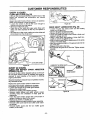
GENERAL
BEFORE USE
RECOMMENDATIONS
The warranty on this unit does not cover items that have
been subjected to operator abuse or negligence. To
receive full value from the warranty, the operator must
maintain unit as instructedin this manual,
Some adjustments will need to be made periodically to
properly maintain your unit.
All adjustments in the "Service and Adjustments" section of
this manual should be checked at least once each season.
• Once a year, replace the spark plug, replace air filter
element and check blades and semi-automatic head for
wear. A new spark plug and a clean/new air filter element assures proper air-fuel mixture and helps your
engine run better and last longer.
• Follow the maintenance schedule in this manual.
DISCONNECT
THI_
SPARK
PLUG
WARNING
BEFORE PERFORMING MAINTENANCE
EXCEPT FOR CARBURETOR ADJUSTMENTS.
REPLACE BLADE OR SEMI-AUTOMATIC
HEAD PARTS THAT ARE CRACKED,
CHIPPED, OR DAMAGED IN ANY OTHER
WAY BEFORE USING THE UNIT.
Bladenut
Semi-automatic head
Assisthandle
Throttle handle
Cylinderand muffler cover
Air filter cover
Muffler
Line limiter - missing or damaged.
° Clean the unit using a damp cloth with a mild detergent
after use.
• Wipe off the unit with a clean dry cloth.
DRIVE SHAFT
GEAR BOx
OGeneral purpose lithium base grease.
_General purpose lithium base grease.
•
°
•
°
•
•
•
°
AND
CLEAN UNIT AND LABELS
CHART
O
CHECK FOR LOOSE FASTENERS
PARTS
AFTER USE
INSPECT THE ENTIRE UNIT. REPLACE
DAMAGED PARTS. CHECK FOR FUEL
LEAKS AND MAKE SURE ALL FASTENERS ARE IN PLACE AND SECURELY FASTENED.
LUBRICATION
CHECK FOR DAMAGED OR WORN PARTS
• Blades - replace blades that are bent, warped, cracked
or damaged in any way.
• Semi-automatic head - replace semi-automatic head
parts that are bent, warped, cracked, or damaged in
any way.
• Fuel cap - replace broken or leaking fuel cap.
• Debds shields - replace debris shields that are bent,
warped, cracked, or damaged in any way.
• Line limiter - missing or damaged.
- 21 -
CUSTOMER
RESPONSIBILITIES
EVERY 5 HOURS
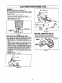
CLEAN AIR FILTER {Fig. 24)
A dirty air filter decreases the life and performance of the
engine and increases fuel consumption and harmful
emissions,
Always clean after 5 tanks of fuel or 5 hours of operation,
Clean more frequently in dusty conditions,
• Loosen the screws on the air filter cover enough to
remove the cover from the engine.
• Remove air filter from cover.
• Clean the air filter using hot soapy water. Rinse with
clean cool water, Squeeze air filter dry and replace in
cover,
• Re-installthe air filter cover, making sure the choke exit
slot is placed over the choke lever.
Figure 25
DRIVE SHAFT LUBRICATION
(Fig. 26)
• Loosen the gear box clamp screw and the locating
screw from the gear box.
: Remove
gear box
from
the
tube.
Remove the
the drive
shaft
from
the
tube.
• Check drive shaft for broken wires, twists or kinks, and
replace if damage is found.
• Using a clean cloth, wipe surface of drive shaft thoroughly to remove any grease or dirt.
• Apply a uniformcoat of lithiumbase grease to the entire
surface of the drive shaft.
* Inject the remainingcontentsof the grease tube into the
top of the tube,
° Replace drive shaft in the tube.
• Re-assemble the gear box to the tube.Tighten screws
securely,
r._
___"_
_/
AIR FILTER
, ,,,,,,u,,,,,,,,,
................
COVER
Figure 24
EVERY 25 HOURS
CLEAN AND INSPECT
SPARK ARRESTOR
SCREEN (Fig. 25)
As the unit is used,carbon deposits buildup on the muffler and spark arrestor screen (if installed), and must be
removed to avoid creating a fire hazard or affecting
engine performance.
//4C£J
=,M,so.Ew
c ,o,
so.,w
Required cleaningis every 25 hours of operationor annually, whichever is less.
Replace the spark arrestor screen if breaks occur.
CLEANING THE SPARK ARRESTOR SCREEN
• Loosen and remove the 2 muffler guard screws.
• Remove the mufflerguard.
• Remove the muffler cover retaining spdngs.
• Remove muffler diffuser and spark arrestor screen
assembly. Notice the orientation of these parts for
reassembly.
• Clean the spark arrestor screen with a wire brush or
replace if breaks are found in the screen.
• Replace any broken or cracked parts.
° Reinstall diffuser and spark arrestor screen assembly,
• Reinstall muffler cover and the two muffler cover retaining springs,
• Reinstall muffler guard and the two muffler guard
screws (15-20 in.lbs.).
Figure 26
- 22
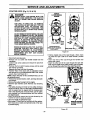
CUSTOMER
YEARLY
REPLACE
RESPONSIBILITIES
•WIRE
SPARK PLUG (Fig. 27)
The spark plug should be replaced each year to ensure
the engine starts easier and runs better. Spark plug gap
should be .025".
• Twist, then pull of spark plug boot.
• Remove spark plug from cylinder and discard.
• Replace with correct spark plug and re-tighten with
spark plug wrench (10-12 flJb.).
• Reconnect spark prug boot.
FUEL LiNE
FUEL
F,L,,"
PLUG
SPARK
BOOT
PLUG
U G__
BARREL
)
NECK
Figure 29
_SPARK
GEAR BOX LUBRICATION
Figure 27
REPLACE
FUEL FILTER (Fig. 28 & 29)
The fuel filter should be replaced after each season.
Never operate your unitwithouta fuel filter.Be careful not
to damage fuel line while removingthe fuel filter.
• Run fuel tank dry of fuel before proceeding with this
step.
Using a small pair of needle nose pliers,grasp fuel cap
i retainer,
emove holding
fuel capitand
in tank
allowit
opening
to hang
anotopull
side
out.
of motor.
With cap out of tank, use a small section of bent wire
similar to that shown in the illustrationto catch fuel line
and stowly pull from tank. When fuel tilter appears in
opening, grasp with fingers and remove from tank.
• Once filter is out of tank. hold fuet line close to fuel filter. Remove fuel filter by twisting and pulling at the
same time.
• Replace fuel filter.
• Reverse process for installation.
RETA|NER
Figure 28
- 23 -
(Fig. 30)
• Remove the gear box screw using a wrench.
• Fill gear box with lithium base gear grease.
• Replace and tighten gear box screw securely.
GEARBOX
,,_J
"_i,_m_[..--_
GEAR BOX
SCREW
_
Figure 30
GEARBOX
ii
i
iii ii
i iiiiii
iiiiiiiii
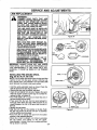
SERVICE AND ADJUSTMENTS
STARTER
ROPE
(Fig. 31, 32 & 33)
REMOVE
CLUTCH HOUSING
SCREWS
NEVER
START THE ENGINE WITH THE
DANGER:
NOSE CONE REMOVED. THE CLUTCH
WILL FLY APART AND CAUSE SERIOUS
INJURY.
USE ONLY A HAND TOOL TO REMOVE
THE CLUTCH. DO NOT USE ANY TYPE OF
MOTORIZED
TOOL OR STRIKE THE
CLUTCH IN ANY WAY. OTHERWISE, THE
CLUTCH WILL FLY APART AND CAUSE
SERIOUS INJURY.
DO NOT REMOVE THE RETAINING TAB AND
SCREW TO REMOVE PULLEY. THE SPRING
BENEATH THE PULLEY IS UNDER TENSION
AND CAN FLY OUT CAUSING SERIOUS
INJURY. IF ANY PART OF THE PULLEY
HOUSING ASSEMBLY IS DAMAGED OTHER
THAN THE ROPE, DO NOT USE. TAKE IT TO
YOUR SEARS SERVICE CENTER,
WIRE
SHOWN WITHOUT
DRIVE SHAFT HOUSING
FOR CLARITY
WHEN RE-INSTALLING
THE CLUTCH,
TIGHTEN THE NUT JUST UNTILTHE
BEVELED
WASHER
IS FLATTENED
AGAINST THE CLUTCH. OVER OR UNDER
TIGHTENING
THE NUT CAN CAUSE
ENGINE DAMAGE.
Figure 31
• Disconnect spark plug wire.
• Remove one (1) screw and throttle handle from the
handlebar.
- Loosen nose cone screws and remove the tube from
nose cone.
• Remove the four clutch housingscrews with the small
hex wrench (provided).
• Separate the nose cone from the engine.
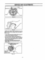
• Hold the "flats"of the clutchwith an adjustablewrench
and remove the nut counterclockwisewitha 9/16" socket
wrench. (See inset Figure 32..)
NOTE: Clutch will slide off the crankshaft intact, Do not
dis-assemb/eclutch.
• Remove the beveledwasher,clutch,and largeflat washer as shown.
• Remove the pulleyhousingfrom the engine.
• Remove rope retention screw. Remove any remaining
rope.
• Hold pulley housing and hand turn the pulley clockwise
as far as it will go.Then, turnthe pulleycounterclockwise
untilthe pulteynotch is aligned with the housingnotch
next to the retainingtab and screw,Next, turn the pulley
one complete turn counterclockwiseuntil the notches
are aligned again.
• insert the long hex wrench into the hole formed by the
notched to hold the pulley in posilion.
• Use a 42" lengthof replacementrope.
° Move away (10 feet) from the fuel tank with the replacement rope. Use a matchand melt bothends of the rope
to prevent fraying.
* Pull the melted ends of the rope through a thick, clean
rag while the rope is still hot to obtain smooth, pointed
ends,
• insert one end of the rope through the handle and
secure with a knot,
° Insert the other end of the rope through the rope exit
hole, into the inside of the pulley housing, into the pulley.
and up through the pulley hole. (See inset Figure33).
PULLEY HOUSING
CLUTCH
LARGE
FLAT
WASHER
Figure 32
- 24 -
BEVELEDWASHER
(CURVES TOWARD
CLUTCH)
ml
i
iiii
i
SERVICE AND ADJUSTMENTS
•
i
ii
• Wrap rope counterclockwise around the pulley ratchet
and tuck loose end under rope where it comes out of
the pulleyhole. Leave a 1-inch tail laying flat on top of
the pulley between the retainer rib and the rope retentionscrew/post.
• Reinstall the rope retention screw into the retention
post.Tightenuntil snug.
NOTE: Do not overtighten the screw. Overtighteningthe
screw can cause the threads in the screw post to strip
out.
• Hold rope taut at rope exit hole so il wig not move and
remove long hex wrench.
• Slowly feed rope into the pulley housing.
• Make sure spacer is in place then reverse steps to
reassemble.
Figure 33
- 25 -
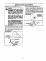
SERVICE AND ADJUSTMENTS
LINE R--E-P-LAC E
MEN'r
........
WARNING:
TRIMMER
HEAD PARTS THAT ARE
CHIPPED, CRACKED, BROKEN, OR DAMAGED IN ANY OTHER WAY CAN FLY
APART AND CAUSE SERIOUS INJURY.
DO NOT USE. REPLACE DAMAGED
PARTS BEFORE USING THE UNIT.
THE LINE SAVER MUST BE INSTALLED
ONLY FROM THE INSIDE OF THE HUB. IF
INSTALLED ON THE OUTSIDE OF THE
HUB, THE LINE SAVER CAN FLY OFF
AND BECOME A DANGEROUS MISSILE.
USE ONLY .080" DIAMETER GOOD
QUALITY LINE. NEVER USEWIRE, ROPE,
STRING, ETC.
THE LOCK RING MUST ENGAGE ALL
FOUR CATCHES WHEN REINSTALLED
OR THE LOCK RING WILL FLY OFF AND
CAUSE SERIOUS INJURY.
USE ONLY SPECIFIED SEARS REPLACEMENT PARTS. USE OF OTHER BRANDS
OF REPLACEMENT PARTS CAN CAUSE
DAMAGE TO YOUR UNIT OR INJURY TO
THE OPERATOR OR OTHERS.
DAMAGE/INJURY CAUSED BY USE OF
ACCESSORIESIATTACHMENTS
NOT
SPECIFICALLY
RECOMMENDED
BY
SEARS WILL NOT BE REIMBURSED.
IMPORTANT: ALWAYS CLEAN DIRT AND DEBRIS
FROM SPOOL AND HUB WHEN PERFORMING ANY
TYPE MAINTENANCE. IF LINE SAVER FALLS OUT,
REINSTALL IT FROM THE INSIDE OF THE TRIMMER
HEAD.
INSTALLING
PRE-WOUND
LOCK RING
Figure 34
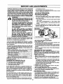
DRIVE
GEAR__
TAP
LOCK RING
Figure 35
SPOOL
(Fig. 34, 35, 36, 37, 38 & 39)
NOTE: The line saver can become wornduring use.After
a groove is worn into line saver, removeit from the hub,
turn it upside down, and reinstall il from the inside (with
spool removed) to provide a new wear surface.
• Hold the semi-automatic head as shown. Press the
lock tab and turn the lock ring as shown.
• Remove the lock ring,tap button, and spool.
• Clean dirt and debris from all parts. Replace the spool
when the square corners on the tugs are rounded off,
reduced in size, or broken off.
• Find "THIS SIDE UP" on spool and insert the end of
the line through the line saver.
• Press spool into the hub, then turn spool enough to
lock lugs under drive gear lugs. Make sure line is not
caught between the rim of the spool and the wail of
the hub.
° Replace the tap button.
• Align the lock ring over the catches on the hub. Push
the lock ring down on the hub and turn it clockwise
until the catches lock into place.
• Pull on the line to change the spoolfrom the locked
positionto the operating position.
• Obtain the correct line length (4-6 inches)by pressing
the tap button and pulling on the Iine again.
Approximately 2 inches of line can be pulled each time
the tap button is pressed.
- 26 -
Figure 36
NORMAL LUGS
WORN LUGS
Figure 37
ill|mr
•
I
iji
L
i|111
i
SERVICE AND ADJUSTMENTS
• •
,,
.
LINE SAVER
CATCH
Figure 38
\
TAP BUTTON
Figure 39
INSTALLING
NEW LINE ON SPOOL (Fig. 40)
NOTE: The line must be wrapped firmly and evenly for
properline feed.
• Follow"INSTALLING PRE-WOUND SPOOL" steps and
remove any line remaining on the spool.
. Use a 40 foot lengthof SEARS •080" diametertine.
• Insert about 1/8 inch of the end of the line through the
hole in the inner rim of the spool. Allow no more than
1/8 inchof fine to extend beyond the rim to avoidinterference with tapping action.
• Wrap the line on the spool as shown by the arrow.
• Follow =INSTALLING PRE-WOUND SPOOL" to complete assembly.
FOR BEST RESULTS, USE ONLY .080"
SEARS BRAND LINE.
WRAP LINE ON
SPOOL AS
SHOWN BY ARROW
LINE
Figure 40
- 27 -
,
•
. ,
...m
,...,
, ..
|1
i
iiiii
SERVICE AND ADJUSTMENT
BRUSH
&
BLADE
SHARPENING
(Fig, 41)
DANGER:
ALWAYS STOP THE ENGINE BEFORE
SHARPENING A BLADE. THE BLADE WILL
CONTINUE TO SPIN AFTER THE ENGINE
STOPS OR AFTER THE THROTTLE TRIGGER
HAS BEEN RELEASED. MAKE SURE THE
BLADE HAS STOPPED COASTINGAND DIS.
CONNECT SPARK PLUG 5EFORE PERFORMING WORK ON THE BLADE.
ALWAYS REPLACE A BLADE THAT IS
BENT, WARPED, CRACKED, OR DAMAGED
IN ANY OTHER WAY. NEVER ATTEMPT TO
STRAIGHTEN AND REUSE A DAMAGED
BLADE. USE ONLY THE SPECIFIED
REPLACEMENT BLADE.
WEED BLADE SHARPENING
(Fig. 42)
• The 4 point, 8 inch blade is reversible. When the cutting edge on one side becomes dull,turn the blade over.
When both sides of cutting edges become dull, the
blade may be resharpened,
• Check blades for flatness periodically. Lay the blade
on a flat surface and inspect the blade for flatness
- beforesharpening,throw away any blade that is not Ilat.
• File or grind each edge in the same manner to maintain a balanced blade.
WEED BLADE
_
FILE OR GRIND EACH
EDGE INTHE SAME
A BALANCEDBLADE
O
MANNER TO MAINTAIN
WEAR PROTECTIVE GLOVES WHEN HANDLING OR PERFORMING MAINTENANCE
ONTHE BLADE TO HELP AVOID INJURY.
TO PREVENTTHE BLADE FROM CRACKING
OR FLYING APART AFTER SHARPENING,
DO NOT RLE WITHIN I/4 INCH OF THE
RADII SHOWN.
, Check blades for flatness periodically. Laythe blade
on a fiat surface and inspect the blade for flatness
before sharpening. Throw away any blade that is not
flat.
• File or grindeach edge in the same manner to maintain a balanced blade.
BRUSH BLADE
FiLE OR GRIND
BLADE AS SHOWN
MAINTA_ RADIUS
IN THIS AREA
SHARPENTHIS
AREA ONLY
MAINTAIN RADIUS
IN THIS AREA
Figure
41
- 28 -
1/4 INCH
_--T--_l
_
MAINTAIN RADIUS'_"-"__._
AREA ONLY
Figure 42
MAINTAIN RADIUS
SERVICE
AND ADJUSTMENTS
t
Carburetor adjustment is critical and if done improperly
can permanently damage the engine as well as the carburetor. Please read all instructions and consult the
Troubleshooting section of this manual before beginning this process. If the engine does not operate according to these instructions after repeating the adjusting
steps, do not use the unit. for further assistance, please
call our customer assistance hotline at !-800-235-5878.
_
MAKE CARBURETORADJUSTMENTSWITH THE
WARNING:
LOWEREND SUPPORTEDTO PREVENTBLADE
OR SEMI-AUTOMATIC
FROM CONTACTINGANY
OBJECT.HOLDUNITWITHYOUR HAND.
THE BLADE OR SEMI-AUTOMATICHEAD WILL
BE SPINNINGDURING MOST OF THIS PROCEDURE. WEAR YOUR PROTECTIVE EQUIPMENT
AND OBSERVEALL SAFETYPRECAUTIONS.
KEEPOTHERSAWAYWHENMAKINGCARBURETOR ADJUSTMENTS.
IN "LOW SPEED MIXTURE ADJUSTMENT,"
RECHECKIDLE SPEED AFTER EACH ADJUSTMENT.THE BLADEOR SEMI-AUTOMATICHEAD
MUSTNOTMOVEAT IDLE SPEED.
CONTACTYOUR SEARS SERVICE CENTER IF
THE IDLE SPEED SETTING CANNOT BE
ADJUSTED SO THAT THE BLADE STOPS AT
IDLE.DONOTUSETHEUNIT UNTILIT HAS BEEN
PROPERLYADJUSTEDOR REPAIRED.
engine does not start, it may be flooded. If in doubt, read
the section on flooded engine in the starting section of this
manual prior to beginning any adjustments.
If you are unsure about adjusting the carburetor or experience any problem while attempting this process, please call
the 1-800 number listed on the front cover of this manual for
further assistance,
as damage can occur.
• Turnidle speed screw clockwise 1/2 turn.
• Start the engine and operate for three (3) minutes to warm
up.Go to "Adjusting procedure"
ADJUSTING PROCEDURE
IDLE SPEED ADJUSTMENT
• Allow the warm engine to idle.
• Adjust the idle speed screw until the engine continues to
run withoutsta,ing and without the blade or semi-auto:
matic head turning.
- Turnscrew clockwise to increase engine speed if engine
stalls or dies.
-Turn screw counterclockwise to slow engine down
and/or to keep the blade or semi-automatic head from
turning.
• No further adjustments are necessary if blade or semiautomatic head does not turn at idle speed and if performance Lssatisfactory.
•HIGH SPEED
MIXTURE ,_
LOW SPEED
MIXTURE SCREW
IDLE SPEED SCREW
Figure 43
LOW SPEED MIXTURE ADJUSTMENT
• AUowengineto idle.
• Turn the low speed mixture screw slowlyclockwiseuntil
the RPM starts to drop. Note the position.
• Turn the low speed mixture screw slowly counterclockwise
The carburetor has been adjusted at the factory for sea level
untifthe RPM speeds up and startsto drop again.Note the
posit{on.
conditions. Adjustments may become necessary if the unit is
used at significantly higher altitudes or ff you notice any of
• Set the low speed mixture screwat the midpoint between
the two positions.
the following conditions:
• Blade or semi.automatichead moves when the engine
HIGH SPEED MIXTURE ADJUSTMENT
runs at idle speed. See "Idle speed adjustment."
IMPORTANT: DO NOT OPERATE ENGINE AT FULL
• Engine will not idle. See"Idle speed adjustment"and "Low
THROTTLE FOR PROLONGED PERIODS WHILE MAKspeed mixture adjustment."
ING HIGH SPEED ADJUSTMENTS AS DAMAGETO THE
• Engine dies or hesitateswhen it should accelerate. See
ENGINE CAN OCCUR.
"Acceleration adjustment:'
• Make a test cut in grass.
• Loss of cutting power which is not corrected ,by air filter
• Based on performanceof the unitwhile cutting,adjust the
cleaning.See "High speed mixtureadjustment:
high speed mixture screw in 1/16 turn incrementsas folNOTE: Do not attemptto adjust the screw beyond the stops
lows:
as damage can occur.
- Clockwise if unitsmokes or losespower while cutting. Do
not adjust for best power by sound or speed, but judge
CARBURETOR PRESETS (Fig. 43)
by how wet/the unit performs during operation.
The Carburetorhas three adjusting screws:
- Counterclockwise if the unithas speed while not cutting,
L = Low speed mixtureadjustingscrew
but dies or lacks power while cutting.
H = High speed mixture adjustingscrew
• Repeat the test cut in grass.
T = Idle speed adjustingscrew
• Continuewith 1/16 turn adjustments until the unit perforIf your engine willnot start due to suspected improper carmance is acceptable while cutting.
buretor adjustment,the following presets may be required.If
• After completingadjustments, check for acceleration.
used, it is recommendedthat a!lsteps withinthe adjustment
• If unit accelerates properly no further adjustmentsare necprocedure be completed in order to assure a properly set
essary. If not, proceed to acceleration check.
carburetor.Ifpresetsare not needed, proceed tosection"Idle
ACCELERATION
CHECK
speed adjustment."
• If the engine dies or hesitates insteadof accelerating, turn
Very small adjustmentscan affect engine performance. It is
the lowspeed mixture screw 1/16of a turnat a time counimportantto turn the screw a very small amount per adjustterclockwiseuntilyou have smoothacceleration.
ment and test performancebefore making further adjust• Check the idle speed for stabilityand that the btade or
ments.Each adjustmentshouldbe no more than the widthof
semi-automatichead does not turn.Adjustas necessary.
the slot in the adjusting screw.
Recheck for smoothaccelerationand stableidle.
• Turn both of the mixture screws counterclockwise until they
o Repeat processas necessary foracceptableperformance.
stop. DO not attempt to adjust the screw beyond the stops
- 29 -
J
i
Ul
i|111
UlU|
i
•
,lllll|=q
ii
t
i
i
STORAGE
iiiiiiii
i
ii
iii
ii
Immediatelyprepare your unit for storage at the end of
the season or if it wilt not be used for 30 days or more.
WARNING:
ALLOW THE ENGINE TO COOL, AND
SECURE THE UNIT BEFORE STORING
OR TRANSPORTING IN A VEHICLE.
STORE UNIT AND FUEL IN AN AREA
WHERE FUEL VAPORS CANNOT REACH
SPARKS OR OPEN FLAMES FROM
WATER HEATERS, ELECTRIC MOTORS
OR SWITCHES, FURNACES, ETC.
STORE UNIT WITH ALL GUARDS IN
PLACE. POSITION SO THAT ANY SHARP
OBJECT CANNOT
ACCIDENTALLY
CAUSE INJURY TO PASSERS BY.
STORE THE UNIT OUT OF THE REACH
OF CHILDREN.
GAS TRIMMER/BRUSHWACKER
INSTRUCTIONS
STORAGE
If your trimmer is to be storedfor a period of time, clean
it thoroughly prior to storage. Remove any dirt, leaves,
oi!, grease, etc. Store in a clean dry area.
• Clean the entire unit.
• Clean air filter. Refer to =Customer Responsibilities".
• Open the semi-automatic line head assembly and
clean any dirt, grass or debds that has collected.
• Inspect the cutting line. Old cutting line may be chalky
or sticky to the touch. Remove and discard old line
and installfresh new line.
• Lightly oil external metal surfaces to prevent rust Irom
forming.
• If your unit is equippedwith a blade, remove it from the
unit. Refer to "Assembly".Apply a coating of oi! to the
entire surface of the blade and wrap in in heavy paper
or cloth.Also, apply a light coat of oit to the arbor shaft
threads, then tighten blade nut for storage.
• Re-assemble all loose parts, being sure that all handles and guards are in place and are securely fastened. Replace any damaged parts.
• The recommended storage position is either vertically
with the fuel cap on top, or horizontally with the rue!
cap up. Do not store unit with the cuffing attachment up.
• Hang the unit by the brackets under the motor housing
to avoid fuel leaks. Make sure the unit is positionedso
that the bladescannot cause injury.
j
A ........... I
WHEN HANDLING LINE LIMITER. THE
CAUTION:
WEAR PROTECTIVE
BLADE IS SHARP
AND CAN CUTGLOVES
YOU.
-30.
i
i
I
Ill!
i i
ii
illll
|
III
FUEL SYSTEM
Never use engine or carburetor cleaner products in the
fuel tank or permanent damage may occur to fuel system components.
Followthese instructions:
• Drain the fuel from the unit into an approved fuel container.
• Drain the fuel lines and carburetor by starting the
: engine and letting it run until it stops.
• Allow the engine to cool before storage.
IMPORTANT: It is important to prevent gum deposits
from forming in essential fuel system parts such as the
carburetor, fuel filter, fuel hose or tank during storage.
Also, experience indicates that alcohol blended fuels,
those that use ethanol or methanol (called gasohol or
oxygenated fuel), can attract moisture and form acidic
gas which will damage your engine. To avoid engine
problems, the fuel system should be emptied before
storage of 30 days or longer.
Fuel stabilizer is an acceptable alternative in minimizing
the formation of fuel gum deposits during storage. Add
stabilizer to the gasoline in the fuel tank or fuel storage
container. Always follow the mix instructions found on
stabilizer containers. Run engine at least 5 minutes after
adding stabilizer to allow the stabilizer to reach the carburetor.
CRAFTSMAN 40:1 2-cycle engine oil (AIR-COOLED) is
specially blended with fuel stabilizer.If you do not use this
Sears oil, you can add a fuel stabilizer (such as CRAFTSMAN No, 33500) to your fuel tank.
INTERNAL ENGINE
• Remove spark plug and pour 1 teaspoon of 40:1 2-cycle
engine oil (AIR-COOLED) through the spark plug opening. Slowly pull the starter rope 8 to 10 times to distribute oil to Inner engine surfaces.
• Replacespark plugwith a new one of the recommended
type and heat range. Referto "Product Specifications".
• Clean air filter. Refer to "Customer Responsibilities".
• Re-install all covers and hardware removed for
access; tighten all screws and fasteners.
• Check entire unit for loose screws, nuts, and bolts.
Replace any damaged, broken, or worn parts.
• Lightlyoil extemal metal surface to prevent rust from
forming.
• Use fresh fuel having the proper gasoline to oil ratio at
the beginningof the next season.
OTHER
- Do not store gasolinefrom one season to another.
• Replace your gasoline can if your can starts to rust.
Rust and/or dirt in your fuel system will cause problems.
• Store your unit in a well ventilated area and covered, if
possible, to prevent dust and dirt accumulation. Do not
cover with plastic. Plastic cannot breathe and will
induce condensationand eventual rust or corrosion.
IMPORTANT: NEVER COVER UNIT WHILE ENGINE
AND EXHAUST AREAS ARE STILL WARM.
iiii iiii i
i
....
TROUBLE
iii
el
i
SHOOTING
iii
= H
=H==
= H
POINTS
=I=====H==
=n,==
........
TROUBLE SHOOTING CHART
SYMPTOM
CORRECTION
,,j
,
1. Fuel tank empty.
2. Engine flooded.
3. Spark plug not firing,
4. Fuel not reaching carburetor.
5. Carburetor requires adjustment.
6. None of the above.
1. Fill tank with correct fuel mixture.
2. See "Starting Instructions".
3. InstalJ new plug/check ignition switch.
4. Reptace fuel filter; inspect fuel line.
5. See "Carburetor Adjustments."
6. Contact your SEARS Service Center/Dept.
Engine willnot
idle properly.
1. Carburetor set too fasi or too slow.
2. Carburetor requires adjustment.
3. None of the above.
1. See "Carburetor Adjustments."
2. See "Carburetor Adjustments."
3. Contact your SEARS Service Center/Dept.
Engine wili not
accelerate, lacks
power, or dies
under a load.
1. Air filter dirty.
2. Spark plug fouled.
Engine will not start or
wil! run only for a
few seconds after
starting.
1. Clean or replace air filter.
2. Clean or replace spark ptug and re-gap.
3. See "Carburetor Adjustments."
4. Contact your SEARS Service Center/Dept,
i 5. Contact your SEARS Service Center/Dept,
3. Carburetor requires adjustment.
4. Muffler outlets plugged.
5. None of the above.
Engine
Smokes
excessively,
!. Air filter dirty.
2. Fuel mixture incorrect.
3. Carburetor requires adjustment.
1. Clean or replace air filter.
2. Refuel with correct fuel mixture.
Engine
runs hot
1. Fuel mixtureincorrect.
2. Spark plug incorrect.
3. Carburetor set too high (lean).
4. Wrongdiameter cuttingIine.(too large)
5. None of the above.
3. See "Carburetor Adjustments."
_L
1, See' "Fueling'"-Your Unit."
2. Replace with correct plug.
3. See Carburetor Adjustments."
4. Use only .080 "diameter cutting line.
_.Contact your SEARS Service Center/Dept.
Cutting head
stops under a load
or does not turn when
engine is accelerated,
'i. Drive shaft not engaged.
2. Drive shaft broken,
1. See "Assembly," "Tube", insert fully.
2. Contact your SEARS Service Center/Dept.
Line does not
advance or breaks
while cutting.
1. Line improperiY';outedin head.
2. Line improperly wound onto spool.
3. Line size incorrect,
4. Old cuttingline.
5, Too littleline outside head.
6. Dirt accumulated in cover.
7. Line wound in wrong direction.
t. Remove cover. Check line
routing.-_-2. rewind line tightly and evenly.
3. Use only .080" diameter line,
4. Replace with new cutting line.
5. Remove cover. Pull 4" of line to outside.
6, Clean cover.
7. Rewind in correct direction.
Line welds onto
spool.
1. Line size incorrect.
2. Old cuttingline.
3. Incorrect spool.
4. Crowding line against material
being cut.
Line purlsback
into head.
1 Too litUeline outside of head.
2. Old cuttingline.
,,, ,.,,,
,, ml i
,,
,, i, i,,,,,,,i i,i ii, i
1, Use only .080" diameter line,
2. Replace with new cutting line.
3. Use proper spool.
4. Cut with tip of line.
5. Reduce cutting speed.
,, ,,,,
i
If situationsoccur whichare not covered in this manua use care and good judgemenL
If you need assistance, contact your SEARS Service Center/Department or the
CUSTOMER ASSISTANCE HO TLINE AT 1-800-235-5878.
- 31 -
i
1. Remove cover. Pull 4" of line to outside.
2. Replace with new cutting line.
REPAIR PARTS
SEARS WEEDWACKER
- MODEL 358.798470
Operator_
Manual
54
f
55
60
•
f,-s
59
27
I Lubrication I
48
4
44
I
14
Key
No.
1
2
3
4
5
6
7
8
9
10
11
t2
13
14
15
16
17
18
19
20
21
22
23
24
25
26
27
28
29
30
31
Part
No.
503-098302
530--094650
STD541025
530-,-014036
530-015971
71,-85807
530--027706
530-069252
530-069256
STD511005
530-094570
534-235901
530-094694
952-030139
530-093896
530-093898
530-340007
530-092o68
530-095121
530-094568
502-208502
502-208602
502-199403
530-094566
530-094640
530-094671
530-094616
530,--094612
5-30--015328
530-001642
530--001711
Key
No.
Description
HH,,
Rocker Switch
Drive Shaft Housing
Nut-Shoulder Ham, Clamp
Handlebar
Screw-Clamp Handlebar
Cutting Head Ass'y.
Drive Shaft Pad
"T" Handle"Ass'y.
Shield Kit Ass'y.
(lncl, #10,11 & 12)
Screw-Line Limiter
Line Limiter
Locknut
Dust Cup
Shaft Lubrication
Hub Ass'y (Incl. 16).
Line Saver
Spring
Cap-Spring
Drive Gear
Gear Box Ass'yo
ThrottleHsg.-Left
Throttle Hsg.-Right
Throttle Lockout
Drive Shaft
Seat Gear Box
Grass Washer
Screw-Grease Refill
Screw-Pinch Clamp
Lockwasher-Pinch Clamp
Lockwasher-Gear Box
Screw-Gear Box
u
32
33
34
35
36
37
3B
40
41
42
43
44
45
46
47
48
49
5O
51
52
53
54
55
56
57
58
59
60
61
62
-32-
Part
No.
502-209602
530-027615
502-199203
530-094572
530-012207
530-094686
530-094417
71-.85787
530.40!183
530--092133
502-209701
530-094627
502-199301
71-85728
530-0t 5792
530-015492
530-015793
503210719
530-047144
530-031159
530-031098
530-029162
530-029163
530-029765
530-027778
530-027749
71-85729
530-083376
503-210738
530-038206
Description
Throttle Lock
Shield Retention Plate
Throttle Trigger
Handlebar Bracket
Handlebar Clamp
Clamp Harness Ass'y.
Shoulder Strap
Spool w/Line
Release Button
Cover
Spring-Trigger
Shield-Metal
Trigger Spring
Brush Blade
Washer-Blade
Washer Befieville--Blade
Nut-Blade
Screw-Throttle Housing
Wire Harness Ass'y,
Hex Wrench (5/32)
Hex Wrench (3/t6)
Decal-Shaft Warning Upper
Decal-Shaft Warning Lower
Decal-Shield
Decal-Handlebar Warning
Decal-Blade Direction
Weed Blade
Operators Manual
Screw-Throttle Housing
Connector-Female
REPAIR
16
_ _
PARTS
19
17
!
I
--_
/22
[
"
32
37 38
44
43
48
52
45
54
59
3O
61
76
77
67
68
63
,sp rca
I Arrestor_
91
-33-
| Gasket I
85
86
87
REPAIR PARTS
i
Key
No.
Part-
,,,,HI
I I
,lllll
I
Description
No.
,,L
1
2
3
4
5
6
7
8
9
:
10
11
530-015773
530-027529
530-027530
530-015849_
530-015852
530-015254
530-038915
530-037930
530-069247
530-069571
530-014362
530-069651
12
t3
14
t 530-O19156
530-014347
530-047320
15
16
17
19
t530-019154
530-027593
530-027594
530-010960
20
21
530-015789
530-010934
22
23
24
530-015126
530--015771
530-014015
25
26
27
28
530-015775
530-047040
530-015772
530-014016
29
30
530-038205
530-047145
31
32
33
34
35
STD610603
!t530-015162
530-025875
530-019178
530-069275
36
37
38
39
40
42
43
44
45
46
47
48
530-032103
530-015787
530-019158
530-0321O2
530-069232
530-027523
530-069257
530-036409
530-016080
530-039134
530-015128
530-069626
Screw-Air Filter Cover
Air Filter Cover
Air Filter
Screw-Carb.
Spacer-Air Filter
Wave Washer-Air Filter
Choke Shutter
Air Filter Plate
Fuel Line Kit
Fuel Line
Return Line
Fuel Pick-up Ass'y.
Carburetor Kit (incL Limiter
Caps
Carburetor Gasket
Fuel Cap Ass'y.
Shroud & Tank Ass'y.
(Incl. #9,10 & 13)
CrankcaselShroud Gasket
Reed Valve
Reed Stop
Connecting Rod Ass'y.
(IncJ. Bearings)
Crankshaft Retaining Ring
Crankshaft Ass'y.
(Incl. #36)
Flywheel Key
Screw-Fan Housing
Crankcase & Crankcase
Ass'y.(IncI. #20,21 & 28)
Screw-Throttle Cable
Throttle Cable Ass'y.
Screw-Fan Housing
Crankcase Ass'y.
(Incl. #36-39)
Connector-Male
Lead Wire/Grommet
Assay,
Screw-Reed Valve
Piston Pin Retainer
Piston Ring
Cylinder Gasket
Piston Kit
(Incl. #32,33, & pin)
Inner Beating
Retaining Ring-C'case
Crankshaft Seal
Beadng Outer
Rope Kit
Retainer-Starter Pulley
Muffler Kit
_iluffler Attachment Spring
Screw-Starter Pulley
ignition Module Kit
Screw-Ignition Module
Cylinder
.....
Ke_
Part
NO.
NO,
49
5O
51
52
53
54
STD PM2
530-015768
530-039 t 36
530-347987
530-038911
530-069291
55
56
57
58
59
60
62
63
64
66
67
68
69
70
71
72
73
74
75
76
77
530-029395
530-027569
530-069672
530-O94189
530-069254
530-069673
530-015767
530-027511
530-015770
530-015769
530-O15496
530-015796
STD541137
530-035164
530-035166
530-035172
53O-O35OO8
530-035139
530-035031
530-035028
530-035014
530-035109
78
79
80
81
82
83
84
85
530-035147
530-035095
530-032158
530-032157
530-035214
530-035208
530-035203
530-069623
86
530-035173
87
530-069276
88
89
90
91
92
93
94
95
530-015239
530-015717
530-038945
952-701612
530-038874
530-016091
530-O38318
530-038317
61
I=,
Description
Spark Plug
Locknut-Pinch Clamp
Flywheel Ass'y.
Washer
Fan Housing
Starter Pulley Kit
(Incl. #45)
Starter Spring
Starter Handle
Pulley Housing Ass'y.
Clutch Washer
Clutch Ass'y. Kit
Clutch Housing
Screw
Spacer-Flywheel
Screw-Fan Housing
Screw-Fan Housing
Screw-Starter PulIey
Washer-Belleville
Nut
*+ Pump Gasket
*+ Pump Diaphragm
+ Inlet Screen
+ Inlet Needle Valve
+ Metering Lever Spring
+ Metering Lever
+ Metedng Pin
*+ Metering Diaphragm
*+ Metering Diaphragm
Gasket
*+ Circuit Plate Gasket
Hi Speed Needle Spring
Hi Speed Needle
Idle Needle
Idle Needle Spring
Idle Speed Spring
Idle Speed Screw
Garb. Kwik Repair Kit
(+indicates Contents)
Carb. Gasket/Diaphragm
Kit (*Indicates Contents)
Engine Gasket Kit
( 1"Indicates Contents)
Screw-Cylinder
Screw-Mullter Guard
Muffler Guard
Spark Arrestor Kit
Primer Bulb Ass'y.
Screw -Primer Bulb Ass'y
Limiter Cap-High Speed
Limiter Cap-Low Speed
Not Shown
530-03892O
530--085223
530-047158
InstructionDecal
Carton
Carton Contents Bag
,l,,,
,34-