1
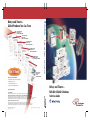
Relays and Timers –
Global Products You Can Trust
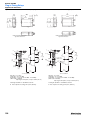
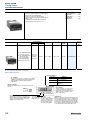
Terminal Block Relay
Product Profile
Pub. No. 700-PP012B-EN-P
General Purpose Relays
Product Profile
Pub. No. 700-PP010A-EN-P
Gold Plated Contacts
Product Profile
Pub. No. 700-PP015A-EN-P
Interposing Relays
Product Profile
Pub. No. 700-PP014A-EN-P
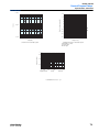
Get It Now!
Solid State Relays
Product Profile
Pub. No.
700SSR-PP001A-EN-P
Three ways to get more information:
Relays and Timers – Selection Guide
General Purpose Timers
Product Profile
Pub. No. 700-PP011A-EN-P
• View publications online at: www.ab.com/manuals/rt
• Order publications online at:
www.the automationbookstore.com
• Contact your local Allen-Bradley distributor
www.rockwellautomation.com
Corporate Headquarters
Rockwell Automation, 777 East Wisconsin Avenue, Suite 1400, Milwaukee, WI, 53202-5302 USA, Tel: (1) 414.212.5200, Fax: (1) 414.212.5201
Headquarters for Allen-Bradley Products, Rockwell Software Products and Global Manufacturing Solutions
Americas: Rockwell Automation, 1201 South Second Street, Milwaukee, WI 53204-2496 USA, Tel: (1) 414.382.2000, Fax: (1) 414.382.4444
Europe/Middle East/Africa: Rockwell Automation SA/NV, Vorstlaan/Boulevard du Souverain 36, 1170 Brussels, Belgium, Tel: (32) 2 663 0600, Fax: (32) 2 663 0640
Asia Pacific: Rockwell Automation, 27/F Citicorp Centre, 18 Whitfield Road, Causeway Bay, Hong Kong, Tel: (852) 2887 4788, Fax: (852) 2508 1846
Headquarters for Dodge and Reliance Electric Products
Americas: Rockwell Automation, 6040 Ponders Court, Greenville, SC 29615-4617 USA, Tel: (1) 864.297.4800, Fax: (1) 864.281.2433
Europe/Middle East/Africa: Rockwell Automation, Brühlstraße 22, D-74834 Elztal-Dallau, Germany, Tel: (49) 6261 9410, Fax: (49) 6261 17741
Asia Pacific: Rockwell Automation, 55 Newton Road, #11-01/02 Revenue House, Singapore 307987, Tel: (65) 6356-9077, Fax: (65) 6356-9011
Publication 700-SG003B-EN-P — June, 2002
Supercedes 700-SG003A-EN-P — May, 2001
Copyright © 2002 Rockwell Automation, Inc. All rights reserved. Printed in USA.
Relays and Timers –
Reliable Global Solutions
Selection Guide
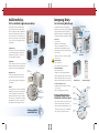
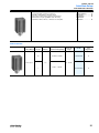
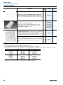
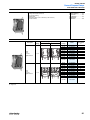
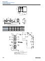
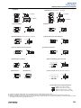
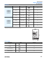
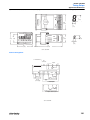
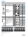
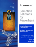
Solid State Relays
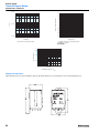
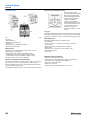
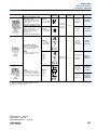
Interposing Relays
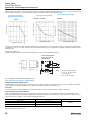
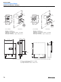
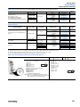
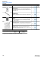
The New Solid State Applications Solution
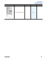
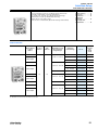
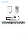
New Cost-Saving Relay Design
Rockwell Automation has broadened its Allen-Bradley relay
Rockwell Automation is introducing a new and improved Allen-
product line to include six new solid-state relays (SSRs). The
Bradley 700-HC “Ice Cube” General Purpose Relay. This 4-pole plug-in
solid-state relay logic input control levels are compatible with
relay has been redesigned to meet your low energy switching
many industrial controllers available in today’s market such as
application needs. Along with the 700-HC, Allen-Bradley is offering a
PLCs and temperature controllers. The switching design of the
new, space-saving 700-HP printed circuit board (PCB) “Pin“ style relay.
solid-state relay uses no moving parts or contacts that can wear
Improved 7A contacts
700-HC Series D
out. This is one of the reasons they will perform in a variety of
• Cost-reduced design
harsh environments.
• Improved low-energy switching capability
Flat Pack Style
Hockey Puck Style
• Increased the Ith switching capability from 5 A … 7 A
Long Life Expectancy
• Same Allen-Bradley relay family appearance on faceplate
Solid-state relays use electronic instead of mechanical devices
• Incorporated manual override lever (-3 option) with the existing
Tube Base Style
for load switching while providing a life cycle expectancy of
approximately 100,000 energized hours or 11.4 years. This
push-to-test button
Larger, brighter LED
• New 700-HC Series A, 2-pole, 10 A version is now available
reduces product replacement and downtime.
Low Maintenance
Manual override and
push-to-test option (-3)
Slim Line Style
700-HC Series D
with silver contacts
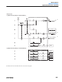
700-HP PCB “Pin” Style
Square Base Style
• PCB or socket mountable
There are no moving parts or contacts to wear out or be affected by
vibration and shock. Maintenance dollars, parts replacement, and
Electrical schematic
Ice Cube Style
downtime are reduced drastically, if not eliminated altogether.
• 5 mm Pin spacing available in a 2-pole, 8 A design
700-A Plug and Play Modules
Heat sink is
DIN rail mountable
• Module mounted within sockets
Reduced Power Costs
• Available as surge suppression, timing and LED modules
The solid-state relay typically requires 25 times less power
• Modules compatible with 700-HN104 socket (for 700-HC relay)
than electromechanical relays and also generates less heat.
• Modules compatible with 700-HN123 socket (for 700-HP relay)
This means the panel can typically be smaller, reducing panel
• Modules compatible with 700-HN153 socket (for 700-HB relay)
space requirements.
700-HP PCB “Pin” Style
700-A Plug and Play Module
Coil and Contact Suppression Sockets
• 700-HN104 (for 700-HC relay), 700-HN123 (for 700-HP relay)
Flexibility
• 12 A, 300V AC rating
Plug-in style SSRs (700-SA, SC, SF and SK) are compatible with
LED provides
input logic side
operational indication
Allen-Bradley 700-HN sockets and retainer clips. In addition, the
700-SA SSR is compatible with the 700-HT1 multi-function,
multi-range timer module while the 700-SC SSR is compatible
Wiring label printed
on faceplate
with the new 700-AT1 or 700-AT2 timer modules. The flexibility
and compatibility with these relay accessories support a wide
Standard LED
• Able to insert optional plug and play 700-A modules
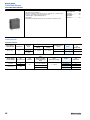
Terminal Block Relays
With Reliable Gold Plated Contacts
Accommodates
1492-SMN81
markers
Built-in coil
surge protection
Built-in reverse
DC polarity protection
• Ensures corrosion will not form on the contact surface over time.
range of applications, while reducing spare parts inventories.
• Switches low energy loads reliably as low as 8V, 2.5 mA.
20-way jumper slots
No-tool relay
replacement
• Ideal for very low energy logic switching applications such as TTL
See Interposing Relays
on Inside Back Cover
drive enables and low energy I/O Cards such as Allen-Bradley
1734, 1746, 1756, 1764, 1771, 1791 and 1792 modules.
Gold plated
contacts
Relays and Timers
1
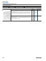
Table of Contents
General Information
•
•
•
•
•
Quick Selection Table
Contact Switching Data
Surge Suppression Solutions
Low Energy Selection Criteria
Catalog Number Index
Page
Page
Page
Page
Page
6
17
21
25
30
Page
Page
Page
Page
Page
31
37
42
47
51
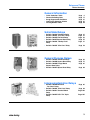
Solid-State Relays
•
•
•
•
•
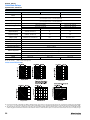
Bulletin 700-SA Tube Base Relay
Bulletin 700-SC "Ice Cube" Relay
Bulletin 700-SE Flat Pack Relay
Bulletin 700-SF Square Base Relay
Bulletin 700-SH "Hockey Puck"
Relay
• Bulletin 700-SK "Slim Line" Relay
Page 58
General Purpose Relays
• Bulletin 700-HA Tube Base Relay
• Bulletin 700-HB Square Base Relay
• Bulletin 700-HD Flange Mount
Square Base Relay
• Bulletin 700-HF Square Base Relay
Page 63
Page 75
Page 81
Page 89
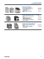
Interposing/Isolation Relays
• Bulletin 700-HC Miniature
"Ice Cube" Relay
• Bulletin 700-HK "Slim Line" Relay
• Bulletin 700-HL Terminal Block
Relay
• Bulletin 700-HP PCB "Pin" Style
Relay
Page 85
Page 98
Page 102
Page 107
3
Relays and Timers
Table of Contents, Continued
Latching Relay
• Bulletin 700-HJ Magnetic Latching
Relay
Page 94
Power Relays
• Bulletin 700-HG Power Relay
• Bulletin700-HHF Flange Mount
Power Relay
Page 111
Page 114
DIN Rail Mounted Timing
Relays
•
•
Bulletin 700-FE Economy Timing
Relay
Bulletin 700-FS High Performance
Timing Relay
Page 116
Page 120
Socket Mounted Timing Relays
• Bulletin 700-HNC Miniature
Timing Relay
• Bulletin 700-HNK Ultra-Slim
Timing Relay
• Bulletin 700-HR Dial Timing Relay
• Bulletin 700-HS Timing Relay
• Bulletin 700-HT Timing Relay
• Bulletin 700-HV Timing Relay
Page 127
Page 133
Page
Page
Page
Page
139
151
156
161
Digital Timing/Counting Relays
• Bulletin 700-HX Multifunction
Digital Timing Relay
• Bulletin 700-HXM Preset
Counter/Timing Relay
4
Page 165
Page 174
Relays and Timers
Table of Contents, Continued
Industrial Relays
• Bulletin 700-CF Control Relay
• Bulletin 700-M Miniature
Control Relay
• Bulletin 700-P Heavy-Duty
Relay
Page 186
Page 205
Page 211
Industrial Safety Control Relays
• Bulletin 700S-CF Safety Control
Relay
• Bulletin 700S-P Heavy-Duty
Safety Control Relay
• Bulletin 700-ZP Self-Monitoring
Relay Assembly
Page 197
Page 202
Page 226
Industrial Timing Relays
• Bulletin 700-PS Solid-State Timing
Relay
• Bulletin 700-RTC Solid-State
Timing Relay
Page 235
Page 238
5
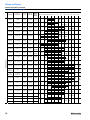
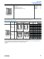
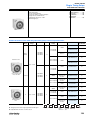
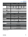
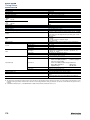
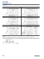
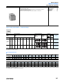
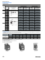
General Information
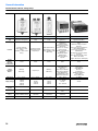
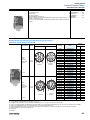
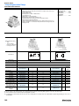
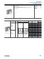
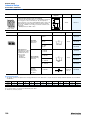
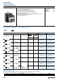
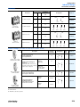
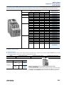
Quick Selection Table for Solid-State Relays
Bulletin No.
700-SH
700-SE
700-SC
Type
Hockey Puck
Flat Pack
Miniature, Ice Cube Socketed
Features
Panel/DIN Mount, High Current, Protective
Cover, LED Status Option
Panel/DIN Mount, Low Profile
Compatible w/700-HN103 or 128 socket,
LED Status & Zero-cross AC Switching
Options
Load Type
AC (47…63 Hz)
AC (47…63 Hz)
AC (47…63 Hz)
DC
Load Voltage Range
24…240V AC, 200…480V AC ➊
75…264V AC
75…264V AC
3…52.8V DC or
3…125V DC
Load Current Max.
(Continuous)
6 A/40 A ➋
5 A/20 A ➋
3A
3A @ 48V, or 2A @
110V
5 mA @ 100V, 10 mA @ 200V
5 mA @ 100V AC,
10 mA @ 200V AC
5 mA @ 50V DC, or
0.1mA @ 100V DC
Yes (optional)
N/A
Max Leakage Current to
5 mA @ 100V, 10 mA @ 200V, 20 mA @ 400V
Load
Zero Cross Load
Switching
Yes
Yes (optional)
Equivalent
Electromechanical
Relay Contact
Arrangement
Form A
Form A
Rated Control (Input)
Voltage
5…24V DC, 100…120V AC, 200…240V AC
5V DC, 12V DC, 24V DC
5…24V DC,
100…110V AC,
200/220V AC
5…24V DC
Yes
No
Yes (optional)
Yes (Opt) for 48V DC
LED Indicator
Mounting Method
Panel w/o heat sink, Panel or DIN w/heat sink Panel w/o heat sink, Panel or DIN w/heat sink
Form A
Panel or DIN w/socket
Dielectric Strength
2500V AC 50/60 Hz 1 min
2000V AC 50/60 Hz 1 min
1500V AC 50/60 Hz 1 min.
Certification
cURus, CE ➊, TÜV
cURus, CE, TÜV
cURus, CE, VDE
Max. Ambient
Operating Temperature
-30…80°C
(no condensation)
-30…80°C
(no condensation)
-30…80°C
(no condensation)
Page Number
51
42
37
➊ 200…480V load voltage range units do not have CE approval.
➋ With heat sink
6
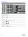
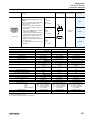
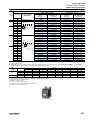
General Information
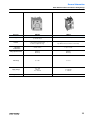
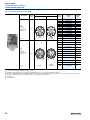
Quick Selection Table For Solid-State Relays, Continued
Bulletin No.
700-SF
700-SA
700-SK
Type
Square Base, Socketed
Tube Base, Socketed
Slim Line, Socketed
Features
Compatible w/700-HN116 socket,
LED status, zero-cross AC
switching
Compatible w/700-HN100, 125,108,
and 202 socket, LED status, zero-cross
switching
Compatible w/700-HN121 socket. Supports Input (sensor)
module or Output (SSR) module
Load Type
Load Voltage
Range
AC
(47…63 Hz)
DC
75…264V AC
Load Current Max.
(continuous)
3 … 52.8V DC
3A
Output Module
AC
(47…63 Hz)
DC
AC
(47…63 Hz)
Input Module
AC
(47…63 Hz)
DC
4 … 60V DC,
Field Input:
40 … 200V DC 60… 264V AC
DC
75…264V AC
3 …125V DC
75 … 264V
AC
Field Input:
6.6… 32V DC
5A
3A
2A
2A @ 60V,
1.5A @ 200V
Supply
Current: 0.1 …
100 mA
Supply Current:
0.1 … 100 mA
Max. Leakage
Current to Load
5mA @ 100V
AC, 10mA @
200V AC
5mA @ 50V DC
5 mA @ 100V
10 mA @ 200V
5 mA @ 125V
1.5 mA
1 mA
5 µA
5 µA
Zero Cross Load
Switching
Yes (optional)
N/A
Yes
N/A
Yes
(optional)
N/A
No
N/A
5 … 24V DC
5 … 24V DC
Equivalent
Electromechanical
Relay Contact
Arrangement
Form A
Rated Control
(input) Voltage
4V DC or 24V DC
Form A
5…24V DC
Form A
5…24V DC
5 … 24 V
DC
5 … 24 V DC
LED Indicator
Yes
Yes
Yes
Mounting Method
Panel or DIN w/socket
Panel or DIN w/socket
Panel or DIN w/socket
Dielectric Strength
1500V AC 50/60Hz 1 min.
1500V AC 50/60Hz 1 min.
4000V AC 50/60 Hz 1 min
Certification
cURus, CE, VDE
cURus, CE, VDE
cURus, CE, TÜV
Max. Ambient
Operating
Temperature
-30…80° C
(no condensation)
-30 … 80°C
(no condensation)
-30 … 80°C
(no condensation)
Page Number
47
31
58
7
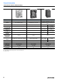
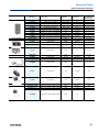
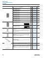
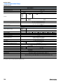
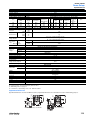
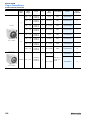
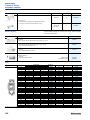
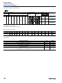
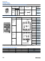
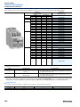
General Information
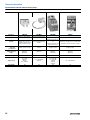
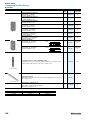
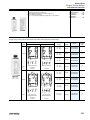
Quick Selection Table For Relays
Bulletin No.
700-HA
700-HB
700-HD
700-HF
Type
General Purpose Relay
General Purpose Relay
General Purpose Relay
General Purpose Relay
Features
Pin Style Terminals,Standard ON/
OFF Flag Indicator, Electrical
Schematic on Face, Clear Cover for
Visual Inspection, Optional Push-totest and Manual Override, Optional
LED
Blade Style Quick Connect Terminals,
Standard ON/OFF Flag Indicator,
Electrical Schematic on Face,
Clear Cover for Visual Inspection,
Optional Push-to-test and Manual
Override,
Optional LED
Flange-mounted, Blade-style Quick
Connection Terminals, Clear Cover
for Visual Inspection
Square Base, Plug-in Quick
Connect Solder Terminals,
Optional Push-to-test and
LED
Contact Form
DPDT, 3PDT
DPDT, 3PDT
DPDT, 3PDT
DPDT, 3PDT, 4PDT
Contact Type
Single, Bifurcated
Single
Single
Single
Contact Material
AgNi, AgNi + Gold
AgCdO
AgCdO
AgCdO
Max. operating
current under
resistive load
10 A
15 A
15 A
10 A
10V 50 mA
10V 50 mA
10V 50 mA
AC: 6V, 12V, 24V, 120V, 240V
DC: 6V, 12V, 24V, 48V, 110V
AC: 6V, 12V, 24V, 120V, 208V, 240V
DC: 6V, 12V, 24V, 48V, 110V
AC: 6V, 12V, 24V, 120V,
240V
DC: 6V, 12V, 24V, 48V, 110V
80…110% of Nominal Voltage at
50 Hz
80…110% of Nominal Voltage at
60 Hz
80…110% of Nominal Voltage at DC
85…110% of Nominal
Voltage at 50 Hz
85…110% of Nominal
Voltage at 60 Hz
80…110% of Nominal
Voltage at DC
Contact Ratings
Min. permissible
load
700-HA
700-HAB
700-HAX
10V
6V
6V
50 mA
30 mA
1 mA
Coil Ratings
AC: 6V, 12V, 24V, 48V, 110V, 120V,
208V, 230V, 240V, 277V
Coil Voltage
DC: 6V, 12V, 24V, 36V, 48V, 60V,
80V, 110V, 125V, 140V, 220V
80…110% of Nominal Voltage at
50 Hz
80…110% of Nominal Voltage at 50 Hz
80…110% of Nominal Voltage at
Permissible Coil
80…110% of Nominal Voltage at 60 Hz
60 Hz
Voltage Variation
80…110% of Nominal Voltage at DC
80…110% of Nominal Voltage at DC
Electrical Ratings
Pole-to-Pole: 2000V
Dielectric
Contact to Coil: 2000V
Withstand Voltage
Contact to Frame: 2000V
Electric Service
Life (cycles)
100,000 minimum
Pole-to-Pole: 2500V
Contact to Coil: 4000V
Contact to Frame: 2500V
Pole-to-Pole: 2500V AC
Contact to Coil:4000V AC
Contact to Frame: 2500V AC
Pole-to-Pole: 1500V AC
Contact to Coil:1500V AC
Contact to Frame: 1500V AC
100,000 minimum
100,000 minimum
200,000 minimum, 500,000
minimum (DPDT)
CE, cULus, cURus, ABS, IMQ, RINA
CE, UR, CSA, ABS, IMQ, RINA
CE, UR, CSA
Reference
Certifications
Socket
Cat. No(s).
Page Number
8
CE, cULus, cURus, ABS, IMQ,
RINA
700-HN100, 700-HN101, 700HN125, 700-HN126,700-HN202
700-HN203
63
700-HN153
700-HN154
75
700-HN116, 700-HN138,
700-HN139
—
81
89
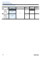
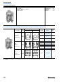
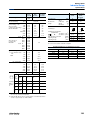
General Information
Quick Selection Table For Relays
700-HC
700-HK
700-HL
700-HP
Interposing/Isolation Relay
Interposing/Isolation Relay
Interposing/Isolation Relay
Interposing/Isolation Relay
Pin Style Terminals,Standard ON/
OFF Flag Indicator, Electrical
Schematic on Face, Clear Cover for
Visual Inspection, Optional Push-totest and Manual Override, Optional
LED
Optional Pilot Light,
Built-in Retainer Clip,
Low Switching Capacity
Ideal for PLC Interfaces, Built-in Coil
Surge Protection, Fully Assembled
Relay/Sockets, Standard LED, Relay or
Solid-state Output
Optional: Leakage Current
Suppression Solution
PCB “Pin Style” Mounting,
5 mm Pin spacing
2PDT, 4PDT
SPDT, DPDT
SPDT (1 c/o)
1 N.O. (SSR)
2PDT
Single, Bifurcated
Single
Single
Single
AgNi, AgNi + Gold
AgCdO, AgCd+Gold
AgSnO
AgNi, AgNi + Gold
10 A (2PDT)
7 A (4PDT)
5 A (DPDT), 10 A (SPDT)
6 A (SPDT), 2 A (SSR)
8A
10V 1 mA (Gold), 10V 10 mA (Silver) 10V 50 mA (Silver), 5V 10 mA (Gold)
AC: 6V, 12V, 24V, 120V, 240V
DC: 6V, 12V, 24V, 48V, 110V
80…110% of Nominal Voltage at
50 Hz
80…110% of Nominal Voltage at
60 Hz
80…110% of Nominal Voltage at DC
Pole-to-Pole: 1600V
Contact to Coil: 1600V
Contact to Frame: 1600V
AC: 6V, 12V, 24V, 120V, 240V
DC: 6V, 12V, 24V, 48V, 110V
12V 6 mA (72 mW) Silver
8V, 2.5 mA (20 mW) Gold
AC: 12V, 24V, 48V, 110V, 120V, 230V,
240V
DC: 12V, 24V, 48V, 125V, 230V, 240V
5V 5 mA (50 mW) Gold,
5V 5 mA (300 mW) Silver
AC: 6V, 12V, 24V, 120V, 240V
DC: 6V, 12V, 24V, 48V, 110V
85…110% of Nominal Voltage at 50 Hz 85…110% of Nominal Voltage at 50 Hz 80…110% of Nominal Voltage at 50 Hz
85…110% of Nominal Voltage at 60 Hz 85…110% of Nominal Voltage at 60 Hz 80…110% of Nominal Voltage at 60 Hz
80…110% of Nominal Voltage at DC
80…110% of Nominal Voltage at DC
73…150% of Nominal Voltage at DC
Pole-to-Pole: 1500V AC
Contact to Coil: 1500V AC
Contact to Frame: 1500V AC
Pole-to-Pole: —
Contact to Coil: 4000V AC
Contact to Frame: 1500V AC
100,000 minimum
100,000 minimum
100,000 minimum
CE, cULus, cURus, IMQ, ABS, RINA
CE, UL, UR, CSA
700-HN103, 700-HN128, 700-HN104
700-HN121
700-HN122
—
700-HN123
85
98
102
107
CE, cURus, cULus, ABS, IMQ
Pole-to-Pole: 2000V AC
Contact to Coil: 5000V AC
100,000 minimum
CE, cULus, cURus, IMQ, ABS, RINA
9
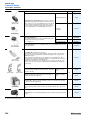
General Information
Quick Selection Table For Relays
Bulletin No.
700-HG
700-HHF
700-HJ
Type
Power Relay
Power Relay
Magnetic Latching Relay
Features
Panel Mount with Screw Terminals, Optional
Magnetic Blowouts for Switching DC Loads,
Optional Snap Action Switch
Flange Mounted, Optional LED
Socket Mounted, Ideal for
Lighting Applications
Contact
Form
SPST-N.O.-DM, SPDT,
DPST-N.O., DPDT
SPST-NO-DM, DPDT, 3PDT
SPDT, DPDT (Single or Dual Coil)
Contact Type
Single
Single
Single
Contact
Material
AgCdO
AgCdO
AgCdO
Max. operating
current under
resistive load
30 A
20 A (3PDT), 25 A (DPDT), 30 A (SPDT)
10 A
Min.
permissible
load
10V 50 mA
10V 50 mA
10V 100 mA (3PDT)
10V 50 mA
Coil Voltage
AC: 24V, 120V, 240V, 277V, 480V
DC: 12V, 24V, 48V, 110V, 220V, 250V
AC: 24V, 120V, 240V
DC: 6V,12V, 24V
AC: 24V, 120V, 240V
DC: 12V, 24V,
Permissible
Coil Voltage
Variation
85…110% of Nominal Voltage at 50 Hz
85…110% of Nominal Voltage at 60 Hz
80…110% of Nominal Voltage at DC
85…110% of Nominal Voltage at 50 Hz
85…110% of Nominal Voltage at 60 Hz
80…110% of Nominal Voltage at DC
85…110% of Nominal Voltage at 50 Hz
85…110% of Nominal Voltage at 60 Hz
80…110% of Nominal Voltage at DC
Contact Ratings
Coil Ratings
Electrical Ratings
Dielectric
Withstand
Voltage
Electric
Service Life
(cycles)
Pole-to-Pole: 2200V AC
Contact to Coil: 2200V AC
Contact to Frame: 2200V AC
Pole-to-Pole: 2200V AC
Contact to Coil: 2200V AC
Contact to Frame: 1600V AC
Pole-to-Pole: 1500V AC
Contact to Coil: 1500V AC
Contact to Frame: 1500V AC
100,000 minimum
100,000 minimum
100,000 minimum
Certifications
CE, UL, CSA
CE, UR, CSA
CE, UR, CSA
Socket
Cat. No(s).
—
—
700-HN153
700-HN154
Page Number
111
114
94
Reference
10
General Information
Quick Selection Table for Relays
Bulletin No.
700-CF and
700S-CF
700-M/MB
Type
Control Relay
Miniature Control Relay
Features
700-P and
700S-P
700-PK
Heavy-Duty Control Relay Heavy-Duty Control Relay
Five Contact Styles,
Mechanically Linked
Smallest Size, Long Life,
Five Contact Styles,
Mechanically Linked
Contacts, Timer and Latch
Low Power Consumption,
Mechanically Linked
Contacts, Timer and
Operations, Switch up to
Mechanically Linked
Contacts, Timer and
Latch Options, Switch up
600V AC and DC
Contacts, Switch up to 600V
Latch Options, Switch up
to 600V AC and DC
700S-CF for Safety Circuits
AC and DC
to 600V AC and DC
700S-P for Safety Circuits
700-R
Sealed Switch
Hazardous Location
Ratings, Long Life in
Dirty Environment,
Timer and Latch
Options, Switch 600V
AC, 300V DC
Contact Form
4-12 Poles Double Break
4-8 Poles Double Break
2-12 Poles Double Break
2-12 Poles Double Break
2-8 Poles
Contact Type
Cross Stamp, Bifurcated
X-Mark and Bifurcated
Bifurcated Double Break
Double Break
Sealed Switch
Contact Material
Silver, Gold
Silver-Copper
Silver-Nickel
Silver-Cadmium Oxide
Sealed Switch
Max. Current AC
Resistive
25 A (Relay)
10 A (Adder Deck)
15 A
10 A
20 A
5A
Min. Load
24V 10 mA (Silver)
12V 8 mA (Gold)
17V, 30 mA (700-M)
17V 5 mA (700-MB)
10V, 50 mA
5V 1 mA (sealed switch)
1 mA, 5V with Bulletin
700-CPR
1 mA, 5V
Coil Voltage
12…600V AC
9…250V DC
24…480V AC
12…220V DC
24…600V AC
6…600V DC
24…600V AC
6…600V DC
24…240V AC
24…250V DC
Coil Voltage Pickup
85…110% AC Coils,
80…110% DC Coils
85…110% AC Coils,
80…110% DC Coils
85…110% AC Coils,
80…110% DC Coils
85…110% AC Coils,
80…110% DC Coils
85…110% AC Coils,
80…110% DC Coils
Dielectric withstand
2640V
2640V
2640V
2640V
2640V
1.2 million at 10 A
120V AC
800K at 10 A 120V AC
1.5 million at 10 A
120V AC
1.5 million at 10 A
120V AC
1.5 million at 5 A 120V
AC
Electrical
Reference
Electric Service Life
(cycles)
Certifications
UL, CSA, CE
UL, CSA, CE
UL, CSA, CE
UL, CSA, CE
UL, CSA, CE
Sockets
DIN Rail or Panel Mount
DIN Rail or Panel Mount
Panel or Rail Mount
Panel or Rail Mount
Panel or Rail Mount
Page Number
186, 197
205
211 and 226
213
229
11
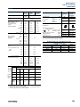
General Information
Quick Selection Table For Timing Relays
Bulletin No.
700-FE
700-FS
700-HR52, -HRP,
-HRS, -HRT, -HRV
700-HRM/-HRC
700-HRF
Type
DIN Rail Timer
DIN Rail Timer
Multifunction Timer
ON-Delay Timer
Twin Timer
Features
Only 17.5 mm wide,
6 A Contact Rating,
Multifunction or
Single Function
22.5 mm wide
8 A Contact Rating,
Multifunction or Single
Function
Dial Timing Relays
5 A Contact Rating
Multiple Programmable Timing
Ranges
Tube Base Pin Style Terminals
Multi-Voltage Inputs
Timed Contacts and
Instantaneous Contacts
Transistor Outputs
Single Function and MultiFunction
7 Different Operating Modes
Dial Timing Relays
5 A Contact Rating
Multiple Programmable Timing
Ranges
Tube Base Pin Style Terminals
Multi-Voltage Inputs
Timed Contacts and
Instantaneous Contacts
Transistor Outputs
Single Function and MultiFunction
Independent ON and OFF
settings
14 time ranges
8-pin models available
Dial Timing Relays
UL508
Control
Outputs:
Time Limit
Instantaneous
1 N.O. or SPDT Timed
SPDT, DPDT,
2 N.O. + 1 common
DPDT Timed, Transistor
SPDT Timed/Instantaneous
DPDT Timed, Transistor
SPDT Timed/Instantaneous
Operation
Modes:
ON-Delay
OFF-Delay
One Shot
Repeat Cycle-Pulse
Fleeting OFF-Delay
Pulse Converter
Star Delta
11 Different Timing
Modes
ON-Delay
OFF-Delay
One Shot
Repeat Cycle Off Start
Repeat Cycle On Start
Signal On/Off-Delay
ON-Delay One Shot
ON-Delay
Repeat Cycle Off Start
Repeat Cycle On Start
Time Range
0.05 s…10 h
0.05s…60 h
0.05 s…300 h
0.05 s…300 h
0.05 s…300 h
Supply Voltage
24V AC/DC
110…240V AC
24V…48V AC/DC
24V…240V AC
12V DC
24V…48V DC
24V…240V AC
12…48V DC
24…48V AC
100…240V AC
100…125V DC
12…48V DC
24…48V AC
100…240V AC
100…125V DC
12V DC
24V AC/DC
48…125V DC
100…240V AC
Contact Rating
at 120V AC
6A
8A
5A
5A
5A
Certifications
cUR, UL, CE
cUR, UL, CE
cURus, CE, ACA
cURus, CE, ACA
cURus, CE, ACA
700-HN100
700-HN125
700-HN100
700-HN125
139
139
Socket Cat.
No(s).
—
—
700-HN100 OR 700-HN101
700-HN125 OR 700-HN126
Page Number
116
120
139
12
DPDT Timed
General Information
Quick Selection Table For Timing Relays
Bulletin No.
700-HRY
700-HRQ
700-HNC
700-HNK
Type
Star-Delta Timer
True OFF-Delay timer
Miniature Timer
Ultra-Slim Timer
Features
A wide star-time range
(up to 120 s)
Star-delta transfer time range
(up to 0.5 s)
UL Recognized
Dial Timing Relays
Long power OFF-Delay Times
11-pin and 8-pin models are available
UL Recognized
Four Different Operating Modes
DIN Rail Mount with Socket
Pin Configuration Same as Bulletin
700-HC Relay
Control Outputs:
Time Limit
Instantaneous
SPST (Star, Delta) Timed
SPST - NO Instantaneous
DPDT Timed
Operation
Modes:
Star-Delta
True OFF-delay Timer
True OFF-delay Timer w/reset
Time Range
0.5 s…120 s
Supply Voltage
Ultra-Slim Timing Relay
4 Different Operating Modes
Three Operating Voltages
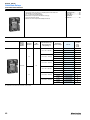
DIN Rail Mount with Socket
Pin Configuration Same as
700-HK Relay
4PDT
SPDT, DPST-NO
ON-Delay
One Shot
Repeat Cycle Off Start
Repeat Cycle On Start
ON-Delay
One Shot
Repeat Cycle Off Start
Repeat Cycle On Start
0.05 s…12 min.
0.1 s…10 h
0.1 s…10 h
100…120V AC
200…240V AC
48V DC
24V AC/DC
100…240V AC
100…125V DC
12V DC
24V AC/DC
48…125V DC
100…240V AC
12V DC
24V DC
24V AC
Contact Rating at
120V AC
5A
5A
5A
5A
Certifications
cURus, CE, ACA
cURus, CE, ACA
cURus, CE, ACA
cURus, CE, VDE, ACA
Socket Cat.
No(s).
700-HN100
700-HN125
700-HN100 OR 700-HN101
700-HN125 OR 700-HN126
700-HN103
700-HN128
700-HN121
700-HN122
Page Number
140
140
127
133
13
General Information
Quick Selection Table For Timing Relays
Bulletin No.
Type
700-HT
700-HV
700-HS
700-HX
700-HXM
Tube Base Timing Relay
Repeat Cycle Timing
Relay
Square Base Timing
Relay
Digital Timer
Digital Counter/Timer
World’s Smallest Compact Preset
Timer
Built-in Prescaling for Counter
Operation
Finger Protection Terminal Block to
Meet VDE0106/P100
Panel Surface Compatible with
NEMA 4/IP66
Six-language Instruction Manual
Provided
Environmentally Friendly—Flash
Memory, No Battery
Negative Transmissive LCD Display
Features
Pin Style Terminals
Single Range or Fixed
Timers
Available as -ON or -OFF
Delays
Pin Style Terminals,
Single Range Timer,
Repeat Cycle
Blade Style Terminals,
Single Range or Fixed
Timers Available as ON
or OFF Delay
Digital Timer
5 A Contact Rating
Negative Transmissive
LCD Display
10 Functions or Modes
Environmentally
Friendly—Flash Memory,
No Battery
NEMA B300 Rated
NEMA 4/ IP66
DIN or Panel Mount
Capable
Control
Outputs:
Time Limit
Instantaneous
DPDT
DPDT
DPDT
SPDT
SPDT
ON-Delay
Repeat Cycle
Signal Off-Delay
One Shot
Accumulative
On/Off-duty AdjustableRepeat Cycle
Counter Multi Mode
Timing
Operation
Modes:
ON-Delay
OFF-Delay
Repeat Cycle
ON-Delay
OFF-Delay
Signal ON-Delay 1 and 2
Signal OFF-Delay
One Shot
Repeat Cycle Off Start
Repeat Cycle On Start
Signal On/Off-Delay
Power ON-Delay 1 and 2
Twin Timer Cumulative
Time Range
0.1 s…30 min.
0.1 s…30 min.
0.1 s…180s.
0.05 s…300 h
0…9999 h
Supply Voltage
12V DC
24V DC
24V AC
120V AC
240V AC
24V DC
24V AC
120V AC
240V AC
12V DC
24V AC
24V DC
120V AC
12…24V DC
24V AC
100…240V AC
24V DC
Contact Rating
at 120V
10 A
10 A
12 A
5A
5A
cURus, CE, NEMA 4/IP66, ACA
Certifications
UR, CSA, CE
UR, CSA, CE
UR, CSA, CE
cURus, CE, NEMA 4/IP66,
ACA
Socket Cat.
No(s.)
700-HN100 OR 700-HN101
700-HN125 OR 700-HN126
700-HN100
700-HN125
700-HN153
700-HN154
700-HN100
700-HN125
—
Page Number
156
161
151
165
174
14
General Information
Quick Selection Table For Industrial Timing Relays
Bulletin No.
100-FPT
700-PT
Type
Pneumatic Timing Module
(for 700-CF relays)
Pneumatic Time-Delay Timer
Features
Timing function works independent of the supply voltage. Relay
contact operates instantaneously.
Continuous adjustment range.
Continuous carrying current of 10 A, Contacts of N.O. and N.C. Open
Type Without Enclosure. Mounts on 700-P relay.
Control Outputs:
Time Limit
Instantaneous
2 timed contacts
1 open, 1 closed
Timing Operation Modes:
ON-Delay
OFF-Delay
ON-Delay
OFF-Delay
Time Range
0.3…180 s
0.1…60 s
Supply Voltage
110…240V
50/60 Hz
110…250V DC
24…600V AC
6…600V DC
Page Number
186
216
15
General Information
Quick Selection Table For Industrial Timing Relays
Bulletin No.
100-ETA
196-MT3
700-RTC
700-PS
Type
Solid-state Timing Module
(for 700-CF relays)
Solid-state Timing Module
(for 700-M relays)
Solid-state Timing Relay
Solid-State Timer
Self-contained or external potentiometer.
Continuous carrying current of 5 A AC or DC.
Stand alone or mount on 700-P or 700-R.
Features
Changes all contacts on
Bulletin 100-C contactors
and Bulletin 700-CF control
relays into timed contacts.
35 mm DIN Rail Mounting
Adapter
Timed and instantaneous
contacts. Sealed contacts
for
harsh environments and
hazardous locations.
Control Outputs:
Time Limit
Instantaneous
4 timed contacts on relay
4 instantaneous to timed
contacts
8 output contacts
3 output contacts
Timing Operation
Modes:
ON-Delay
OFF-Delay
ON-Delay
ON-Delay
OFF-Delay
ON-Delay
OFF-Delay
Time Range
0.1…180 s
0.1…30 s
0.05 s…64 min.
0.1…120 s
110…120V 50/60 Hz
235
16
Supply Voltage
110…240V
50/60 Hz
24V DC
110…250V DC
110…250V AC/DC
50/60 Hz
24V AC
110…120V AC
220…240V AC
24V DC
120V DC
240V DC
Page Number
186
206
238
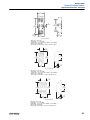
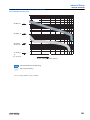
Relays and Timers
General Information
Contact Data Tables
Contact
Arrangement
Contact
Style
Contact
Material
NEMA
Pilot
Duty ➊
700-CF
Up to 8 form X
or 8 form Y
cross
stamped
Ag
A600
P600
700-CFB
Up to 8 form X
or 8 form Y
bifurcated
gold
AgCuAu
—
700-MB
Up to 8 form X
or 8 form Y
bifurcated
AgCu
A300
Q300
700-M
Up to 8 form X
or 8 form Y
single
“X”mark
AgCu
A600
Q600
700-CPR
➋
N.O. or N.C.
cartridge
single
sealed
—
NiAg
A600
P600
AC and DC Switching Capability
1 mA
20 mA 50 mA 100 mA
1A
3A
5A
24V
10 A
DC
20 A
25 A
30 A
35 A
AC
12V
IEC
Relay
Type
NEMA
700-P
Up to 12 form X or
bifurcated
8 form Y
17V
AC
DC
17V
5V
DC
10V
AC (0.5 A Max.) (150V)
(0.2 A Max.)
(30V)
DC
700-PK
Up to 12 form X or
8 form Y
single
AgCdO
2X A600
2X P600
10V
700-PH
Up to 6 form X
or 4 form Y
tandem
AgCdO
A600
P600
10V
700-R
Up to 8 form A
or form B
sealed sw.
W
B300
C600
P300
5V
AC
DC
700-RM
Up to 8 form A
or form B
sealed sw.
W
B300
C600
P300
5V
AC
DC
700-RTC
Up to 4 form A
or form B
sealed sw.
W
B600
P300
5V
AC
DC
700S-CF
Up to 8 form X
or 8 form Y
cross
stamped
Ag
A600
P600
NiAg
A600
P600
700S-P
Up to 12 form X or
bifurcated
8 form Y
24V
AC
DC
AC
DC
AC
DC
(20 A Lighting Load)
AC
(35 A
Lighting Load)
AC
10V
AC
➊ NEMA contact rating chart is on page 19.
❷ Cartridge for 700-P relays for low energy switching.
17
Relays and Timers
General Information, Continued
Contact Data Tables, Continued
AC and DC Switching Capability
Relay Type
Contact
Arrangement
Contact
Style
Contact
Material
NEMA
Pilot
Duty ➊
700-FE
1 N.O.
single
AgCdO
D300
10V
700-FS
1, 2 form C
single
AgCdO
B300
10V
700-HA
2, 3 form C
single
AgNi
B300
10V
700-HAB
2, 3 form C
bifurcated
AgNi
—
700-HAX
2, 3 form C
bifurcated
Au/AgNi
—
700-HB
2, 3 form C
single
AgNi
B300
700-HC14
4 form C
single
Ag/Au
C300
Q300
700-HC22
2 form C
single
AgNi
B300
Q300
10 V
700-HC24
4 form C
single
AgNi
C300
Q300
10 V
700-HD
2, 3 form C
single
AgCdO
B300
1 mA 10 mA 50 mA 100 mA 1 A
AC
DC
3A
5A
10 A
20 A
25 A
30 A
35 A
(24V Max.)
AC
DC
(24V Max.)
AC
DC
(24V Max.)
AC
DC (24V Max.)
6V
AC
DC (24V Max.)
6V
AC
DC (24V Max.)
10V
AC
DC
10V
(30V Max.)
AC
DC
AC
DC
(30V Max.)
AC
10V
(24V Max.)
General Purpose
DC
AC
DC
700-HF
2, 3, 4 form C
single
AgCdO
B300
10V
700-HG
1 form X, 1 form C,
2 form A, 2 form C
single
AgCdO
A600
10V
AC
DC
700-HG
with
Blowouts
1 form X
single
AgCdO
A600
10V
AC
DC
700-HG
with
Blowouts
1, 2 form C,
2 form A
single
AgCdO
A600
10V
AC
DC
700-HHF45
1 form X
single
AgCdO
A600
10V
AC
DC
700-HHF62
2 form C
single
AgCdO
B600
10V
700-HHF73
3 form C
single
AgCdO
B300
700-HJ
1, 2 form C
single
AgCdO
—
700-HK36
1 form C
single
AgCdO
B300
AC
DC
AC
DC
10V
AC
DC
10V
1 form C
single
Au/AgCdO
—
700-HK32
2 form C
single
AgCdO
B300
700-HKX32
2 form C
single
Au/AgCdO
—
DC
5V
18
(24V Max.)
AC
DC
(30V
(30V
Max)
Max)
(28V
Max.)
(110V
Max.)
(110V
Max.)
(28V
Max.)
(28V Max.)
(28V Max.)
AC
10V
700-HKX36
(30V Max.)
Relays and Timers
General Information, Continued
Contact Data Tables, Continued
Relay Type
Contact
Arrangement
Contact
Style
Contact
Material
700-HLS
Solid-State 1 N.O.
—
—
NEMA
Pilot
Duty ➊
—
General Purpose
700-HLT
1 Form C
single
AgSnO
700-HLT_ _X
1 Form C
single
AgSnO
B300
R300
B300
R300
B300
Q300
AC and DC Switching Capability
1 mA
10 mA 50 mA 100 mA 1 A
3A
3V
5A
10 A
20 A
25 A
30 A
35 A
AC/DC
12V
6 A AC/DC
8V
6 A AC/DC
5V
(300 mW)
5V
(50 mW)
700-HP
2 Form C
single
AgNi
8 A AC/DC
700-HPX
2 Form C
single
AgNi + Gold
—
700-HS
2 Form C
single
AgCdO
B300
10V
700-HT
2 form C
single
AgCdO
B300
10V
8 A AC/DC
AC
(30V Max.)
DC
AC
DC
(30V Max.)
➊ NEMA contact rating chart is on page 19.
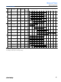
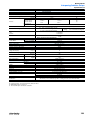
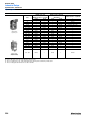
NEMA Ratings and Test Values for AC Control Circuit Contacts at 50 or 60 Hz
Maximum Current [A]
NEMA
Contact Rating
Designation
A150
A300
A600
B150
B300
B600
C150
C300
C600
D150
D300
D600
2X A300
2X A600
120V
240V
480V
600V
VA
Thermal Continuous
Test Current [A]
Make
Break
Make
Break
Make
Break
Make
Break
Make
Break
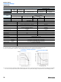
10
10
10
5
5
5
2.5
2.5
2.5
1.0
1.0
0.5
20
20
60
60
60
30
30
30
15
15
15
3.60
3.60
1.80
120
120
6.00
6.00
6.00
3.00
3.00
3.00
1.50
1.50
1.50
0.60
0.60
0.30
12
12
—
30
30
—
15
15
—
7.5
7.5
—
1.8
—
60
60
—
3.00
3.00
—
1.50
1.50
—
0.75
0.75
—
0.30
—
6.00
6.00
—
—
15
—
—
7.5
—
—
3.75
—
—
—
—
30
—
—
1.50
—
—
0.75
—
—
0.375
—
—
—
—
3.00
—
—
12
—
—
6
—
—
3
—
—
—
—
24
—
—
1.20
—
—
0.60
—
—
0.30
—
—
—
—
2.40
7200
7200
7200
3600
3600
3600
1800
1800
1800
432
432
216
14400
14400
720
720
720
360
360
360
180
180
180
72
72
36
1440
1440
NEMA Ratings and Test Values for DC Control Circuit Contacts
Maximum Current [A]
NEMA
Contact Rating
Designation
N150
N300
N600
P150
P300
P600
Q300
Q600
2X P600
Thermal Continuous
Test Current [A]
5…28V
125V
250V
301…600V
Make or Break at
300V or less [VA]
10
10
10
5.0
5.0
5.0
2.5
2.5
10
10
10
10
5.0
5.0
5.0
2.5
2.5
10
2.2
2.2
2.2
1.1
1.1
1.1
0.55
0.55
2.2
—
1.1
1.1
—
0.55
0.55
0.27
0.27
1.1
—
—
0.40
—
—
0.20
0.11
0.11
0.40
275
275
275
138
138
138
69
69
275
19
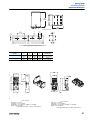
Relays and Timers
General Information, Continued
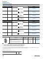
Solid-State Relays Data Tables
Solid-State
Relay Type
Equivalent EM
Relay Contact
Configuration
700-SA
Form A
700-SC
Form A
700-SE ➊
Form A
700-SF
Form A
700-SH ➊
Form A
700-SKO
Form A
Load
Voltage
Maximum AC and DC Switching Capability
Load
Zero-Cross Switching 1 mA 10 mA 50 mA 100 mA 1 A
3A
5A
10 A 20 A 25 A
Device
AC
Yes
Triac
DC
N/A
Transistor
AC
Yes
Triac
DC
N/A
Transistor
Yes
Triac
AC
AC
Yes
Triac
DC
N/A
Transistor
AC
Yes
Thyristor
or Triac
AC
Yes
Triac
DC
N/A
Transistor
30 A
35 A 40 A
(2 A)
(2 A)
➊ Requires a heat sink to reach maximum current value
NEMA Definitions for Contact Arrangements
Form “A” Contacts
A Form A contact arrangement is one that has single-pole, single-throw, normally open contacts. The function of this arrangement is to close a circuit when
actuated.
Form “B” Contacts
A Form B contact arrangement is one that has single-pole, single-throw, normally closed contacts. The function of this arrangement is to open a circuit when
actuated.
Form “C” Contacts
A Form C contact arrangement is one that has single-pole, double-throw contacts with three terminals - one for normally open, one for normally closed, and
one common. The function of this arrangement is to transfer a circuit when actuated.
Form “X” Contacts
or
A Form X contact arrangement is one which has single-pole, single-throw, normally open double-make contacts. The function of this arrangement is to close
a circuit when actuated.
or
Form “Y” Contacts
A Form Y contact arrangement is one that has single-pole single-throw normally closed double-break contacts. The function of this arrangement is to open
a circuit when actuated.
Form “Z” Contacts
A Form Z contact arrangement is one that has single-pole, double-throw, contacts with four terminals — two for normally open and two for normally closed.
The function of this arrangement is to open one circuit and close the other.
20
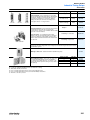
Relays and Timers
General Information, Continued
Surge Suppression Information
Cat. No (s).
See 700-CF Relay
See 700-M Relay
See 700-R Relay
Suppression
Technique
For use with
Max. Relay Contact
Dropout Time
Max. Transient
Voltage Relative to
System Voltage
700-ADL1
700-HC (6…24V DC)
Diode + LED
3X
—
700-ADL1R
700-HB, -HP (6…24V DC)
Diode + LED
3X
—
700-ADL2
700-HC (28…60V DC)
Diode + LED
3X
—
700-ADL2R
700-HB, -HP (28…60V DC)
Diode + LED
3X
—
700-ADL3
700-HC (110…220V DC)
Diode + LED
3X
—
700-ADL3R
700-HB, -HP (110…220V DC)
Diode + LED
3X
—
700-AR1
700-HB, -HC, -HP (6…24V AC/DC)
RC
No Effect
—
700-AR2
700-HB, -HC, -HP (110…240V AC/DC)
RC
No Effect
—
700-AV1R
700-HB, -HC, -HP (6…24V AC)
Varistor + LED
No Effect
—
700-AV3R
700-HB, -HC, -HP (110…240V AC)
Varistor + LED
No Effect
—
700-CF built-in
—
Diode
—
6…10X
100-FSC
100C, 700-CF
R-C Ckt
No Effect
3X
100-FSV
100C, 700-CF
MOV
No Effect
—
100-FSD
100C, 700-CF
Diode
70…95 ms
6…10X
100-JE
100C, 700-CF
Diode
5X
6…10X
700-M built-in
—
Diode
—
6…10X
199-MSMA
100-M, 700-M
R-C Ckt
No Effect
3X
199-MSMV
100-M, 700-M
MOV
No Effect
—
199-MSMD
100-M, 700-M
Diode
5X
6…10X
700-N5
700-P, 700-N
RC
No effect
3X
700-N24
700-P, 700-N
RC
No effect
3X
700-R built-in
—
Diode
—
6…10X
199-FSMA1, FSMA2
700-P, 700-H, 700-CF, 700-M, 700-DCR
RC
No effect
3X
199-FSMA9, 10, 11
700-P, 700-H, 700-CF, 700-M, 700-DCR
MOV
No effect
—
199-FSMZ
700-P, 700-H, 700-CF, 700-M, 700-DCR
Diode
5X
—
21
Relays and Timers
General Information, Continued
Surge Suppression Information, Continued
Cat. No (s.)
Suppression
Technique
For use with
Max. Relay Contact
Dropout Time for
4-pole
700-HSV1
No effect
700-HSV2
—
MOV
Max. Transient
Voltage Relative to
System Voltage
6…10X
—
700-HSV3
700-HA
700-HSMD
22
Diode
—
—
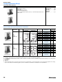
Relays and Timers
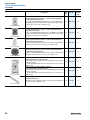
General Information, Continued
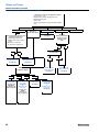
General Purpose Relay Selection Criteria
Do you know what type of relay fits your application?
(industrial, safety, or general purpose)
Yes
No
Does the application present a potential
hazard to the user or machinery?
Which does the application require: a hazardous environment,
safety, industrial, or general purpose relay?
No
Yes
Hazardous
Environment
Which issue is the hazard: a
Machine Safety (Control Reliability) ➊ or
Hazardous Environment ➋ issue?
Hazardous
Environment
Bulletin 700-R relay
see page 229
Bulletin 700-R relay
see page 230
Machine Safety
(Control Reliability)
See Bulletin 440R
Selection Guide
(Pub. Safety-CG001-A-US-P)
Machine Safety
(Control Reliability)
Industrial
General
Purpose
See general
purpose relay
(page 24) or lowenergy general
purpose relay
(page 25) selection
criteria
See industrial relay
(page 26) or lowenergy industrial
relay (page 27)
selection criteria
See Bulletin 440R Selection Guide
(Pub. Safety-CG-001-A-US-P)
Does the application require
any of the following:
•
•
•
•
•
•
•
Positively Guided Contacts ➌
> 4 contacts per relay
> 1 million Electrical Operations ➍
> 300V on coil or contacts
inductive loads greater than 1 A DC
pneumatic timing or latch attachments
double break design to reduce contact
welding?
Yes
No
Does the application
require switching of
less than 24V and less
than 24 mA?
No
See industrial relay
selection criteria (page
26)
Does the application
require switching of
less than 24V and less
than 24 mA?
Yes
See low-energy industrial
relay selection criteria
(page 27)
No
See general purpose
relay selection criteria
(page 24)
Yes
See low-energy general
purpose relay selection
criteria (page 25)
➊ Machine Safety (Control Reliability) — A single component failure within a device or system shall not prevent the normal stopping action from taking place shall
prevent successive machine motion unless the failure is removed.
➋ Hazardous Environment — An environment where a sealed contact is necessary to prevent potential ignition of liquids, gases, vapors, combustibles, or fibers.
➌ Contacts that are all mechanically linked to allow detection of a welded N.O. contact by examining a N.C. contact.
➍ Electrical Operations — If the relay is required to perform over 1,000,000 operations at a load current close to the relay current rating, the best choice is typically an
industrial relay. For many loads, an industrial relay will provide over 1,000,000 operations. If the relay is required to perform over 1,000,000 operations at a load current
that is a small fraction of the relay current rating and none of the other characteristics apply, a general purpose relay may suffice.
23
Relays and Timers
General Information, Continued
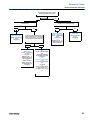
General Purpose Relay Selection Criteria, Continued
Which type of relay does the application require?
•
•
•
•
•
Power relay ( > 15 A)
Miniature relay or interposing/isolation relay
Magnetic latching relay
Classic Style
Special contact with low-energy switching capability
relay
Magnetic Latching
Power
Bulletin 700-HJ relay
see page 94
Does the application have any of the
following characteristics?
•
•
•
•
Classic Style
Miniature or
interposing/isolation
Switching larger DC loads
Auxiliary snap switch for alarm
circuits
Open-style construction
No finger-safe requirements
Will surge
suppressors or timing
modules be used
together with the
relay?
No
No
Which base style does
the relay require?
Yes
Blade
Bulletin 700-HG
panel-mount relay
see page 111
Bulletin 700-HHF
flange-mount relay
see page 114
Bulletin 700-HB
(2PDT, 3PDT) relay
see page 75
Which contact
configuration applies?
SPDT
Bulletin 700-HK
(10 A) relay
see page 98 or
Bulletin-HL
(6 A) relay (2 A)
SSR see page 102
24
2PDT
Yes
3PDT
Bulletin 700-HF
(10 A) relay
see page 89
or
Bulletin 700-HK
(5 A) relay
see page 98 or
Bulletin
700-HC(10 A)
relay see page 85
4PDT
Bulletin 700-HF
(10 A) relay
see page 89
Bulletin 700-HC
(7 A, 10 A) relay
see page 85
or
Bulletin 700-HF
(10 A) relay
see page 89
Pin
Bulletin 700-HA
(2PDT, 3PDT) relay
see page 63
Special Contact
Relays and Timers
General Information, Continued
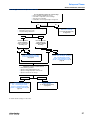
Low-Energy General Purpose Relay Selection Criteria
Does the application require contact
switching capability below 5 mA?
No
Yes
Does the application require a miniature or
slim line relay?
No
Does the application require a 4PDT contact
configuration or a miniature relay?
Yes
Bulletin 700-HAB
(2PDT, 3PDT) relay
(25 mA…3 A switching
@ 6V)
see page 64
Is the environment relatively free of
airborne chemicals that could create
a film on the contacts or react with
the silver-based contact material?
No
Bulletin 700-HKX2
(DPDT) relay
(10 mA…5 A switching
@ 5V)
see page 98 or
Bulletin 700-HL_ _X
(SPDT) relay (8V, 2.5
mA) see page 102
or
Bulletin 700-HC14
(4PDT) relay (1 mA...7
A switching @ 10V)
see page 85
No
Yes
Bulletin 700-HAX
(2PDT or 3PDT) relay
(1 mA…3 A switching
@ 6V)
see page 65
or
Bulletin 700-HL _ _X
(SPDT) relay (8V, 2.5
mA) see page 102
Bulletin 700-HC14
(4PDT) relay
(1 mA…7 A switching
@ 10V)
see page 85
Yes
Bulletin 700-HC24 (4PDT)
relay
(10 mA…7 A switching @
10V)
see page 85 or Bulletin
700-HL Relay (12V, 6 mA)
see page 102
or
Bulletin 700-HK32 (DPDT)
relay
(10 mA…5 A switching @
5V)
see page 98
or
Bulletin 700-HC22 (2PDT)
relay (10 mA,...7 A
switching @ 10V) see page
85
25
Relays and Timers
General Information, Continued
Industrial Relay Selection Criteria
Does the application require any of the following?
•
•
•
Contact load above 10 A AC or 5 A DC
Convertible or replaceable contact cartridges?
Mixture of different contact types to match range of load
characteristics
No
Yes
Does the application require either of the following?
•
•
Which contact load best fits
the application?
More than 8 contacts per relay
Pneumatic timing attachments
No
Does the application
require a miniature
relay or a low power
consuming coil?
No
Yes
0…10 A AC
0…5 A DC
Yes
Does the application
require finger-safe
terminals or DIN Rail
Mounting?
No
Bulletin 700-M relay
(finger-safe terminals,
DIN Rail mountable)
see page 205
Yes
Bulletin 700-CF relay
(finger-safe terminals,
DIN Rail mountable)
see page 186
Does the application have only one of the following
requirements at a time, or several at once?
•
•
•
•
•
Many switching operations
Operation under highly inductive loads
Operation in high-temperature environments
Operation at reduced coil voltages
Mounting in a non-vertical plane
One or Two
Two or More
Bulletin 700-CF relay
(finger-safe contacts,
DIN Rail mountable)
see page 186
Bulletin 700-P relay
(Heavy-duty
applications, panel
mountable)
see page 226
➊ Mixture of contact types is permitted.
26
Bulletin 700-P relay
see page 226 ➊
10…20 A AC
5…10 A DC
Bulletin 700-PK relay
see page 226 ➊
20…35 A AC
10…20 A DC
Bulletin 700-PH relay
see page 226 ➊
Relays and Timers
General Information, Continued
Low-Energy Industrial Relay Selection Criteria
Does the application require any of the following?
•
•
•
•
Contact switching capability below 5 mA
Convertible or replaceable contact cartridges
Sealed logic reed cartridge
Combination of low-energy and higher energy loads
No
Yes
Bulletin 700-P relay with 700CPR contact cartridge
(1…500 mA switching @ 5V)
see page 226 ➊
Does the application require any of the following?
•
•
More than 8 contacts per relay
Pneumatic timing attachments
No
Yes
Does the application
require a miniature
relay or a low power
consuming coil?
No
Does the application
require finger-safe
terminals or DIN Rail
Mounting?
Yes
No
Bulletin 700-MB relay
(5 mA…10 A switching @ 17V AC)
(5 mA…3 A switching @ 17V DC))
see page 205
Yes
Bulletin 700-CF relay
(20 mA…10 A switching @ 17V AC) (20
mA …5 A switching @ 17V DC)
(30 mA…10 A switching @ 20V AC)
(30 mA…5 A switching @ 20V AC) see
page 186
Does the application have only one of the following
requirements at a time, or several at once?
•
•
•
•
Many switching operations
Operation under highly inductive loads
Operation in high-temperature environments
Operation at reduced coil voltages
One or Two
Bulletin 700-CF relay
(20 mA…10 A switching @ 17V AC) (20
mA …5 A switching @ 17V DC)
(30 mA…10 A switching @ 20V AC)
(30 mA…5 A switching @ 20V AC) see
page 186
Two or More
Bulletin 700-P relay with 700-CPR
contact cartridge
(1…500 mA switching @ 5V)
see page 226
➊ Bulletin 700-CPR cartridge is not direct drive.
27
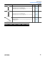
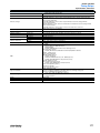
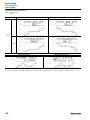
Relays and Timers
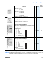
General Information, Continued
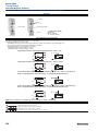
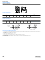
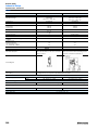
Timing Relay Selection Criteria
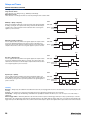
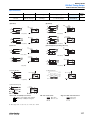
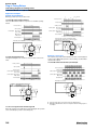
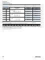
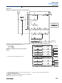
Single Function Timers
Timers that have only 1 timing mode (e.g., ON-Delay or OFF-Delay).
Multi-Function Timers
Timers that have 4…8 timing modes that are selected by turning the mode selection switch.
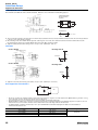
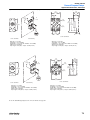
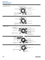
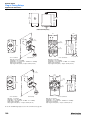
RESET
ON-Delay or (Delay on Operate)
When power is applied continuously (or when power and a start signal are applied),
the timing cycle begins. The output contacts change state after the time delay is
completed. The contacts will return to their normal state when a reset signal is
applied or power is removed.
POWER
ON
OFF
START SIGNAL
ON
OFF
OUTPUT CHANGED STATE
NORMAL STATE
TIME DELAY
RESET
OFF-Delay or (Delay on Release)
Power is applied continuously. When a start signal is applied, the output contacts
change state immediately. When the start signal is removed, the timing cycle
begins. The output contacts will return to their normal state once the time delay is
completed. Reset will occur when a reset signal is applied or power is removed.
POWER
ON
OFF
START SIGNAL
ON
OFF
OUTPUT CHANGED STATE
NORMAL STATE
TIME DELAY
RESET
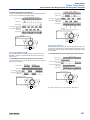
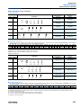
One Shot or (Repeat Cycle)
Power is applied continuously. When a start signal is applied, the output contacts
change state immediately and the timing cycle begins. The output contacts will
return to their normal state once the time delay is completed. Reset will occur when
a reset signal is applied or power is removed.
POWER
ON
OFF
START SIGNAL
ON
OFF
OUTPUT CHANGED STATE
NORMAL STATE
TIME DELAY
RESET
Repeat Cycle or (Flicker)
Power is applied continuously. When a start signal is applied, the timing cycle
begins. When the time delay is completed, the output contacts change state and
the next timing cycle begins. This cycle will repeat until a reset signal is applied or
power is removed.
POWER
ON
OFF
START SIGNAL
ON
OFF
OUTPUT CHANGED STATE
NORMAL STATE
OFF
TIME
ON
TIME
OFF
TIME
ON
TIME
OFF
TIME
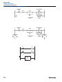
Flexibility
Mounting — Timing relays are available in several different models. They can be plugged into the same socket as the relay, or use a separate plug-in socket
mounting.
Contacts — The contacts are of various types and ratings. Refer to the appropriate specification pages for more details.
Functionality — Timing relays with multi-range and multi-function capability are available. This allows you to stock one relay to cover a wide variety of
applications.
External Trigger Switch — OFF-Delay, One-Shot, and other timer functions require an external trigger switch (from a relay or push button) to control the
timing function. The external trigger switch will cause the timing function to start. In OFF-Delay, the trigger switch closes to energize the output and when the
trigger switch opens the OFF-Delay starts to time out. At the end of the time delay, the output is de-energized and the output contacts return to their shelf state.
28
Relays and Timers
General Information, Continued
Solid-State Relay Glossary
Terms
Meaning
Basic insulation
Insulation for basic protection from electric shock (IEC950 1.2.9.2)
Supplemental insulation
Independent insulation provided outside of basic insulation to protect from electric shock when the basic
insulation breaks down (IEC950 1.2.9.3)
Reinforced insulation
A single-layer of insulation (IEC950 1.2.9.5) that provides the same protection from electric shock as double
insulation (insulation including both basic and supplemental insulation) according to conditions stipulated in
IEC950 standards
Insulation
Circuit
functions
Input
Output
Zero cross circuit
A circuit that starts operation with the AC load voltage at close to zero-phase.
Trigger circuit
A circuit for controlling the triac or thyristor trigger signal, which turns the load current ON and OFF.
Isolated input circuit
If the external circuit is prone to generating noise, or if wires from external sources are prone to the influence of
inductive noise, in order to prevent malfunctions due to noise, it is necessary to electrically isolate internal
circuits and external circuits (output circuits). An isolated input circuit is a circuit that isolates inputs and outputs
by using components that are not connected electrically but that can transmit signals, such as contact relays or
photocouplers.
Photocoupler
A component that runs the electric signal into a light emitter (e.g., LED), changes it to a light signal, and then
returns it to an electric signal using a photoelectric conversion element, such as a photo transistor. The space
used for transferring the light signal is isolated thus providing good insulation and a high propagation speed.
Rated voltage
The voltage that serves as the standard value of an input signal voltage
Pickup (must-operate)
voltage
Minimum input voltage when the output status changes from OFF to ON.
Input impedance
The impedance of the input circuit and the resistance of current-limiting resistors used. Impedance varies with
the input signal voltage in case of the constant current input method.
Operating voltage
The permissible voltage range within which the voltage of an input signal voltage may fluctuate.
Dropout (Reset) voltage
Maximum input voltage when the output status changes from ON to OFF.
Input current
The current value when the rated voltage is applied.
Load voltage
This is the effective value for the power supply voltage that can be used for load switching or in the continuousOFF state.
Maximum load current
(continuous)
The effective value of the maximum current that can continuously flow into the output terminals under specified
cooling conditions (i.e., the size, materials, thickness of the heat sink, and an ambient temperature radiating
condition).
Leakage current
The effective value of the current that can flow into the output terminals when a specified load voltage is
applied to the SSR with the output turned OFF.
Output ON voltage drop
The effective value of the AC voltage that appears across the output terminals when the maximum load current
flows through the SSR under specified cooling conditions (such as the size, material, and thickness of heat
sink, ambient temperature radiation conditions, etc.).
Minimum load current
(continuous)
The minimum load current at which the SSR can operate normally.
Snubber circuit
A circuit consisting of a resistor R and capacitor C, which prevents faulty ignition from occurring in the SSR
triac by suppressing a sudden rise in the voltage applied to the triac.
Semiconductor output
element (switching
element)
This is a generic name for semiconductors such as the thyristor, triac, power transistor, and power MOS FET.
In particular, triacs are often used in SSRs because they allow switching to be performed with one element.
Repetitive peak OFF-state
voltage (VDRM)
This is a rating for an output semiconductor that used in an SSR for AC loads.
Collector-emitter voltage
(VCEO)
This is a rating for an output semiconductor that used in an SSR for DC loads.
Operating (pick-up) time
A time lag between the moment a specified signal voltage is imposed to the input terminals and the output is
turned ON.
Release (drop-out) time
A time lag between the moment the imposed signal input is turned OFF and the output is turned OFF.
Insulation resistance
The resistance between the input and output terminals or I/O terminals and metal housing (heat sink) when DC
voltage is imposed.
Dielectric strength
The effective AC voltage that the SSR can withstand when it is applied between the input terminals and output
terminals or I/O terminals and metal housing (heat sink) for more than 1 minute.
Ambient temperature and
humidity (operating)
The ranges of temperature and humidity in which the SSR can operate normally under specified cooling, input/
output voltage, and current conditions.
Characteristics
Others
Storage temperature
The temperature range in which the SSR can be stored without voltage imposition.
Inrush current resistance
A current which can be applied for short periods of time to the electrical element.
Counter-electromotive
force
Extremely steep voltage rise which occurs when the load switched or turned OFF.
Recommended applicable
load
The recommended load capacity which takes into account the safety factors of ambient temperature and
inrush current.
Bleeder resistance
The resistance connected in parallel to the load in order to increase apparently small load currents, so that the
ON/OFF of minute currents functions normally. (It is also used to shunt leakage currents.)
29
Relays and Timers
Catalog Number Index
Cat. No.
Page
700-A . . . . . . . . . . . . . . . . . . . . . . . . . . . . 86
100-ETA . . . . . . . . . . . . . . . . . . . . . . . . . 189
100-FA . . . . . . . . . . . . . . . . . . . . . . . . . . 188
100-FL . . . . . . . . . . . . . . . . . . . . . . . . . . 190
100-FS . . . . . . . . . . . . . . . . . . . . . . . . . . 190
100-FPT . . . . . . . . . . . . . . . . . . . . . . . . . 189
100-JE . . . . . . . . . . . . . . . . . . . . . . . . . . 191
100-SA . . . . . . . . . . . . . . . . . . . . . . . . . . 188
195-MA . . . . . . . . . . . . . . . . . . . . . . . . . . 206
196-MT . . . . . . . . . . . . . . . . . . . . . . . . . . 206
700-CF . . . . . . . . . . . . . . . . . . . . . . . . . . 186
700-CFZ . . . . . . . . . . . . . . . . . . . . . . . . . 187
700-CP . . . . . . . . . . . . . . . . . . . . . . .219,220
700-CR . . . . . . . . . . . . . . . . . . . . . . . . . . 232
700-DCM. . . . . . . . . . . . . . . . . . . . . . . . . 205
700DC-P . . . . . . . . . . . . . . . . . . . . . . . . . 212
700DC-PH. . . . . . . . . . . . . . . . . . . . . . . . 215
700DC-PK. . . . . . . . . . . . . . . . . . . . . . . . 213
700DC-PL . . . . . . . . . . . . . . . . . . . . . . . . 217
700DC-PPT. . . . . . . . . . . . . . . . . . . . . . . 216
700-DC-PT . . . . . . . . . . . . . . . . . . . . . . . 216
700-DC-R . . . . . . . . . . . . . . . . . . . . . . . . 230
700-DC-RM. . . . . . . . . . . . . . . . . . . . . . . 231
700-FE . . . . . . . . . . . . . . . . . . . . . . . . . . 117
700-FS . . . . . . . . . . . . . . . . . . . . . . . . . . 122
700-HA3 . . . . . . . . . . . . . . . . . . . . . . . . . . 63
700-HAB . . . . . . . . . . . . . . . . . . . . . . . . . 64
700-HAX . . . . . . . . . . . . . . . . . . . . . . . . . . 65
700-HB . . . . . . . . . . . . . . . . . . . . . . . . . . . 75
700-HC . . . . . . . . . . . . . . . . . . . . . . . . . . . 85
700-HD . . . . . . . . . . . . . . . . . . . . . . . . . . . 81
700-HF . . . . . . . . . . . . . . . . . . . . . . . . . . . 89
700-HG . . . . . . . . . . . . . . . . . . . . . . . . . . 111
700-HK3 . . . . . . . . . . . . . . . . . . . . . . . . . . 98
700-HLS . . . . . . . . . . . . . . . . . . . . . . . . . 102
700-HLT . . . . . . . . . . . . . . . . . . . . . . . . . 102
700-HNC . . . . . . . . . . . . . . . . . . . . . . . . . 127
700-HNK . . . . . . . . . . . . . . . . . . . . . . . . . 133
700-HP . . . . . . . . . . . . . . . . . . . . . . . . . . 107
700-HR . . . . . . . . . . . . . . . . . . . . . . . . . . 139
700-HRC . . . . . . . . . . . . . . . . . . . . . . . . . 139
700-HRF . . . . . . . . . . . . . . . . . . . . . . . . . 139
30
Cat. No.
Page
700-HRM . . . . . . . . . . . . . . . . . . . . . . . . 139
700-HRY . . . . . . . . . . . . . . . . . . . . . . . . 140
700-HRQ . . . . . . . . . . . . . . . . . . . . . . . . 140
700-HT12 . . . . . . . . . . . . . . . . . . . . . . . . 156
700-HT22 . . . . . . . . . . . . . . . . . . . . . . . 156
700-HTF . . . . . . . . . . . . . . . . . . . . . . . . . 157
700-HX . . . . . . . . . . . . . . . . . . . . . . . . . . 165
700-HXM . . . . . . . . . . . . . . . . . . . . . . . . 174
700-M . . . . . . . . . . . . . . . . . . . . . . . . . . . 205
700-MB . . . . . . . . . . . . . . . . . . . . . . . . . 205
700-MP. . . . . . . . . . . . . . . . . . . . . . . . . . 221
700-N23 . . . . . . . . . . . . . . . . . . . . . . . . . 222
700-N24 . . . . . . . . . . . . . . . . . . . . . . . . . 222
700-N25 . . . . . . . . . . . . . . . . . . . . . . . . . 235
700-N26 . . . . . . . . . . . . . . . . . . . . . . . . . 235
700-N3 . . . . . . . . . . . . . . . . . . . . . . . . . . 222
700-N4 . . . . . . . . . . . . . . . . . . . . . . . . . . 222
700-N5 . . . . . . . . . . . . . . . . . . . . . . . . . . 222
700-P . . . . . . . . . . . . . . . . . . . . . . . . . . . 212
700-PB . . . . . . . . . . . . . . . . . . . . . . . . . . 219
700-PC . . . . . . . . . . . . . . . . . . . . . . . . . . 219
700-PH . . . . . . . . . . . . . . . . . . . . . . . . . . 215
700-PK . . . . . . . . . . . . . . . . . . . . . . . . . . 213
700-PKT. . . . . . . . . . . . . . . . . . . . . . . . . 216
700-PL . . . . . . . . . . . . . . . . . . . . . . . . . . 217
700-PLL . . . . . . . . . . . . . . . . . . . . . . . . . 221
700-PPT . . . . . . . . . . . . . . . . . . . . . . . . . 216
700-PS . . . . . . . . . . . . . . . . . . . . . . . 220,235
700-PT . . . . . . . . . . . . . . . . . . . . . . . . . . 220
700-R . . . . . . . . . . . . . . . . . . . . . . . . . . . 230
700-RA. . . . . . . . . . . . . . . . . . . . . . . . . . 232
700-RM . . . . . . . . . . . . . . . . . . . . . . . . . 231
700-RTC. . . . . . . . . . . . . . . . . . . . . . . . . 238
700-SA . . . . . . . . . . . . . . . . . . . . . . . . . . . 31
700-SC . . . . . . . . . . . . . . . . . . . . . . . . . . . 37
700-SE . . . . . . . . . . . . . . . . . . . . . . . . . . . 42
700-SF . . . . . . . . . . . . . . . . . . . . . . . . . . . 47
700-SH . . . . . . . . . . . . . . . . . . . . . . . . . . . 51
700-SK . . . . . . . . . . . . . . . . . . . . . . . . . . . 58
700S-CF. . . . . . . . . . . . . . . . . . . . . . . . . 197
700-TB . . . . . . . . . . . . . . . . . . . . . . . . . . 103
700Z-P . . . . . . . . . . . . . . . . . . . . . . . . . . 226
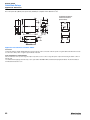
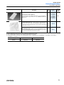
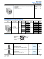
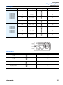
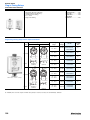
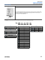
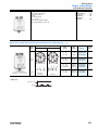
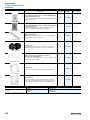
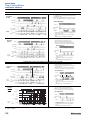
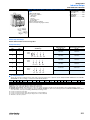
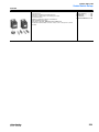
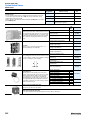
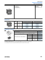
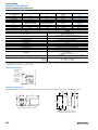
Bulletin 700-SA
Solid-State Relays
Overview/Product Selection
Bulletin 700-SA
Table Of Contents
•
•
•
•
•
Product Selection . . . . . . .
Accessories . . . . . . . . . . . .
Specifications . . . . . . . . . .
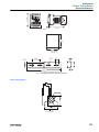
Approximate
Dimensions . . . . . . . . . . . .
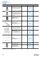
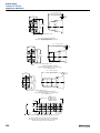
5 A (Resistive) Max. Continuous Load Current
264V AC or 125V DC Max. Load Voltage Range
Photocoupler Isolation Between Control and Load Voltage
LED Indicator for Input/Logic ON/OFF Status Monitoring
700-HN100, -HN125, -HN 202, or -HN108 Socket Compatible
31
32
34
36
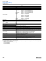
Product Selection
Input-to-Output
Isolation Method
Zero Cross
Function
LED
Indicator
Yes
Photocoupler
Rated Output (Load) Max.
Current and Voltage Range
5 A @100…240V AC
Yes
—
Rated
Input Control
Voltage
Cat. No.
Factory-stocked
Item
(Single Pack)
700-SAZY5Z25
✔
700-SANY3Z25
✔
5…24V DC
3 A @ 5…110V DC
31
Bulletin 700-SA
Solid-State Relays
Accessories
Description
Pkg. Quantity
Cat. No.
Factory-stocked Item
Screw Terminal Tube Base Socket — Panel
or DIN Rail Mounting; Guarded Terminal
Construction
Order ten or multiples of ten
10
700-HN100
✔
Specialty Socket
8-pin backwired socket with solder terminals
Order ten or multiples of ten
10
700-HN108
✔
Screw Terminal Tube Base Socket — Panel
or DIN Rail Mounting; Open Style
Construction
Order must be for 10 sockets or multiples of
10. No retainer clip required.
10
700-HN125
✔
DIN Rail Mounting Pack
Standard 35 x 7.5 mm DIN Rail, 1 meter long,
10 rails per package. Order must be for 10
rails or multiples of 10.
10
199-DR1
✔
Pre-printed identification tags — contains
10 sheets of pre-printed and blank tags. Each
sheet contains 13 sets of the markings
CR…9CR, TR…9TR, M…9M, F, R, 1S, and
117 blank tags. Tags are peel-off with sticky
backing for easy placement on relays.
10
700-N40
Blank identification tags — contains 10
sheets of blank identification tags for
customer specialized printing. Each sheet
contains 546 blank tags. Tags are peel-off
with sticky backing for easy placement on
relays.
10
700-N41
Retainer Clip for Cat. No. 700-HN153
Sockets with 700-SA Relays
Secures relay in socket. Order must be for 10
clips or multiples of 10.
10
700-HN158
✔
8-Pin Socket — can be used with or without
timing attachment
Order ten or multiples of ten
10
700-HN202
✔
Cat. No. 700-HN100
Cat. No. 700-HN108
Cat. No. 700-HN125
Cat No. 199-DR1
Sample Retainer Clips
32
Bulletin 700-SA
Solid-State Relays
Accessories, Continued
Description
Multi-Function Multi-Range Time Module
Pkg. Quantity
Cat. No.
1
700-HT2
Factory-stocked Item
Cat. No. 700-HT2
33
Bulletin 700-SA
Solid-State Relays
Specifications
Control/Input Ratings
Cat. No.
Control Voltage Levels
Rated Control
Voltage
Operating Control
Voltage Range
Impedance
5…24V DC
4…30V DC
1.5 K Ω (+20% -10%)
700-SAZY5Z25
700-SANY3Z25
Pick-up Voltage
Drop-out Voltage
4V DC max.
1V DC min.
Load/Output Ratings
Applicable Load
Cat. No.
Rated Load Voltage
Continuous Load Current
(Resistive)
Load Voltage Range
Max. Inrush Current ➊
Max. ➋
—
—
—
Min.
700-SAZY5Z25
100…240V AC
75…264V AC
0.1 A
5.0 A
80 A, @50/60 Hz for 1 cycle
700-SANY3Z25
5…110V DC
3…125V DC
0.1 A
3.0 A
12 A (10 ms)
Characteristics
Item
700-SAZY5Z25
Load Switching Method/Device
700-SANY3Z25
Triac
Transistor
Pick-up time
1/2 cycle of load power source + 1 ms max.
0.5 ms max.
Drop-out time
1/2 cycle of load power source + 1 ms max.
2.5 ms max.
Output ON voltage drop
1.6 V (RMS) max.
1.5 V max.
Output Leakage current
5 mA max. (at 100V AC); 10 mA max.
(at 200V AC)
5 mA max.
(at 125V DC)
Output VDRM VCEO (V)
600
150
Output di/dt (A/uS)
50
—
Output dv/dt (V/uS)
500
—
Output I2t (A2S)
41.6
—
Output Tj (°C) Max.
125
150
Insulation resistance
100 MΩ min. (at 500V DC)
Dielectric strength
1,500V AC, 50/60 Hz for 1 min.
Vibration resistance (max.)
10…55 Hz, 1.5 mm double amplitude (10 G)
1,000 m/s2 (100 G)
Shock resistance (max.)
Ambient temperature
Operating
Storage
–30…80°C (–22…176°F) with no icing or condensation
–30…100°C (–22…212°F) with no icing or condensation
Ambient humidity
45…85% (no condensation)
Standards
UL508, CSA C22.2 , VDE, CE
Weight
Approx. 70 g
➊ If the SSR operation is continuous ON/OFF, this value should be reduced by 50%. Refer to “Inrush Current Resistivity” graphs below.
➋ Refer to the following graph "Load Current Vs. Ambient Temperature Characteristics" for additional load current details.
Load Current vs. Ambient Temperature
Characteristics
700-SA
Load current (A)
700-SAZY5Z25
700-SANY3Z25
Inrush current (A. Peak)
700-SA
Inrush Current Resistivity ➌
700-SAZY5Z25
700-SANY3Z25
Ambient temperature (°C)
Energizing time (ms)
➌ Inrush current resistivity is the ability of an SSR to withstand a large surge current for a short period of time. Surges are considered non-repetitive (max. repeatability
once every 5 seconds). Keep the inrush current to half the rated value if it occurs repetitively. Exceeding the non-repetitive inrush current will damage the SSR.
34
Bulletin 700-SA
Solid-State Relays
Specifications, Continued
Terminal Arrangement (Bottom View)
(–)
Load
Load
Load
power
supply
(
Input
)
(+)
Input voltage
–
Note:
+
The plus and minus symbols shown
in parentheses are for DC loads.
Basic Application Considerations
High Density Mounting of Multiple SSRs
If multiple SSRs are installed side by side be aware that the outer case wall of the SSR serves to dissipate heat. Install the relays so that they are adequately
ventilated. If poor ventilation is unavoidable, reduce the load current to half.
Protective Component
When controlling AC inductive loads, connect an inrush/surge absorbing device (varistor) across the SSR load terminals. If the SSR has built-in surge
suppression (Bulletins 700-SE and 700-SH) and additional surge suppression is required, connect the varistor across the terminals of the load device . Select
a varistor that meets the conditions of the load voltage outlined in the table below.
Load Voltage
Varistor Voltage
100…120V AC
240…270 V
200…240V AC
440…470 V
380…480V AC
820…1000 V
Varistor Surge Resistance
1000 A min.
For additional details applying solid-state relays, refer to pub. 700-AT001A-EN-E, "Solid-State Relay Application Guide" available at
www.theautomationbookstore.com.
35
Bulletin 700-SA
Solid-State Relays
Approximate Dimensions
Note: All units in millimeters unless otherwise indicated. Dimensions are not intended to be used for manufacturing purposes.
700-SA
➊
35 max.
35 max.
➊ Bulletin 700-SA is compatible with cat. nos. 700-HN100, -108, -125, and -202 (sockets).
36
52.5 max.
Bulletin 700-SC
Solid-State Relays
Overview/Product Selection
Bulletin 700-SC
Table Of Contents
•
•
•
•
•
•
Product Selection . . . . . . .
Accessories . . . . . . . . . . . .
Specifications . . . . . . . . . .
Approximate
Dimensions . . . . . . . . . . . .
3 A (resistive) Max. Continuous Load (Output) Current
264V AC, 48V DC or 125V DC Max. Load Voltage Range Options
5…24V DC or 110/220V AC Control (Input) Voltage Options
LED Indicator (Optional) For Input/Logic ON/OFF Status Monitoring
700-HN103, 700-HN104, or 700-HN128 Socket Compatible
Compatible with 700-AT1 or 700-AT2 Timer Module
37
38
39
41
Product Selection
Input-to-Output
Isolation Method
Zero Cross
Function
Photocoupler
Yes
LED
Indicator
Rated Output (Load)
Max. Current and Voltage
Range
3 A @100…240V AC
Photocoupler
Phototriac
5…24V DC
700-SCZY3Z25
✔
100/110V AC
700-SCZY2A1
✔
✔
200/220V AC
700-SCZY2A2
3 A @100…240V AC
24V DC
700-SCTY3Z24
✔
No
3 A @ 4…48V DC
5…24V DC
700-SCNY3Z25
✔
4…24V DC
700-SCZN3Z26
✔
24V DC
700-SCTN3Z24
✔
3 A @ 4…48V DC
4…24V DC
700-SCNN3Z26
✔
2 A @ 5…110V DC
5…24V DC
700-SCNN2Z25
✔
Yes
3 A @ 100…240V AC
No
No
Photocoupler
Cat. No.
No
Yes
Phototriac
2 A @ 100…240V AC
Factorystocked
Item
(Single
Pack)
Rated Input Control
Voltage
N/A
37
Bulletin 700-SC
Solid-State Relays
Accessories
Description
Pkg. Quantity
Cat. No.
Factory-stocked Item
Screw Terminal Socket — Panel or DIN Rail
Mounting; Guarded Terminal Construction
Order must be in ten or multiples of ten
1
700-HN103
✔
Screw Terminal Socket – Panel or DIN Rail
Mounting. Guarded Terminal Construction
14-blade miniature socket for use with
Bulletin 700-SC relays. This socket has coil
and contact separation as well as the ability
to plug in optional plug in modules (700-A**
accessories: LED, Surge Suppression,
Timing Modules)
10
700-HN104
✔
Screw Terminal Base Socket — Panel or
DIN Rail Mounting; Open Style
Construction
Order must be in multiples of ten
10
700-HN128
✔
DIN Rail Mounting Pack
Standard 35 x 7.5 mm DIN Rail, 1 meter long,
10 rails per package. Order must be for 10
rails or multiples of 10.
10
199-DR1
✔
Pre-printed identification tags — contains
10 sheets of pre-printed and blank tags. Each
sheet contains 13 sets of the markings
CR…9CR, TR…9TR, M…9M, F, R, 1S, and
117 blank tags. Tags are peel-off with sticky
backing for easy placement on relays.
10
700-N40
Blank identification tags — contains 10
sheets of blank identification tags for
customer specialized printing. Each sheet
contains 546 blank tags. Tags are peel-off
with sticky backing for easy placement on
relays.
10
700-N41
Retainer Clip
Secures relay in socket. Order must be for
10 clips or multiples of 10.
10
700-HN114(B)➊
ON-Delay Time Module
Voltage Range: 12…24V AC/DC
used with 700-HN153 socket
1
700-AT1
One Shot Timing Module
Voltage Range: 12…24V AC/DC
used with 700-HN153 socket
1
700-AT2
Cat. No. 700-HN103
Cat. No. 700-HN104
Cat. No. 700-HN128
Cat No. 199-DR1
Sample Retainer Clips
➊ Series B retainer clip must be used with Bulletin 700-SC
38
✔
Bulletin 700-SC
Solid-State Relays
Specifications
Control/Input Ratings
Control Voltage Levels
Cat. No.
Rated Control
Voltage
Operating Control Voltage
Range
Impedance
700-SCZY3Z25
5…24V DC
4…28V DC
15 mA max. ➊
4V DC max.
1V DC min.
700-SCZY2A1
100/110V AC
75…125V AC
41 KΩ± 20%
75V AC max.
20V AC min.
700-SCZY2A2
200/220V AC
150…250V AC
72 KΩ ± 20%
150V AC max.
40V AC min.
700-SCTY3Z24
24V DC
19.2…28.8V DC
2 KΩ ± 20%
19.2V DC max.
4V DC max.
Pick-up Voltage
700-SCNY3Z25
5…24V DC
4…28V DC
1.5 KΩ + 20%/–10% ➋
700-SCZN3Z26
4…24V DC
3…28V DC
15 mA max. ➊
3V DC max.
700-SCTN3Z24
24V DC
19.2…28.8V DC
2 kΩ ± 20%
19.2V DC max.
700-SCNN3Z26
4…24V DC
700-SCNN2Z25
5…24V DC
3…28V DC
1.5 KΩ + 20%/–10% ➋
3V DC max.
Drop-out Voltage
1V DC min.
Load/Output Ratings
Applicable Load
Cat. No.
Rated
Load Voltage
Load Voltage Range
—
—
—
Continuous Load Current
(Resistive)
Min.
Max. ➍
0.1 A
3A
Max. Inrush Current ➌
—
700-SCZY3Z25
700-SCTY3Z24
700-SCZN3Z26
100…240V AC
75…264V AC
700-SCTN3Z24
700-SCZY2A1
700-SCZY2A2
100…240V AC
700-SCNN3Z25
700-SCNN2Z25
0.1 A
2A
4…48V DC
3…52.8V DC
0.1 A
3A
18 A (10 ms)
5…110V DC
3…125V DC
0.1 A
2A
10 A (10 ms)
700-SCNY3Z26
➊
➋
➌
➍
45 A (@50/60 Hz, 1 cycle)
With constant current input circuit system. SSR impedance varies with a change in input voltage.
Input impedance attains its maximum at the operating voltage.
If the SSR operation is continuous ON/OFF, this value should be reduced by 50%. Refer to “Inrush Current Resistivity” graphs on page 40 for details.
Refer to the following "Load Current Versus Ambient Temperature Characteristics" graphs on page 40 for additional load current details.
Characteristics
Cat. No.
700-SCZ….
700-SCT
700-SCNN3…
Triac
Load Switching Method/Device
700-SCNN2…
Transistor
1/2 of load power source + 1 ms
max. (DC input)
1 ms max
0.5 ms max
0.5 ms max
1/2 of load power source +
1 ms max
2 ms max
2.5 ms max
1.6 V (RMS) max
1.6V (RMS)
1.5 V max.
1.5V max.
Output Leakage Current
5 mA max (@ 100 V AC)
10 mA max (@ 200 V AC)
2.5 mA max
(@ 100 V AC)
5 mA max (at 200 V AC)
5 mA max (@ 50 V DC)
0.1 mA max (@ 100 V
DC)
Output VDRM, VCEO
(V)
600
600
80
80
Output di/dt (A/uS)
50
50
—
—
Output dv/dt (V/uS)
250
250
—
—
Output I2t (A2S)
18
18
—
—
Output Tj °C Max.
125
125
150
150
Pick-up Time
3/2 of load power source + 1 ms
max. (AC input)
1/2 of load power source + 1 ms
max. (DC input)
Drop-out Time
3/2 of load power source + 1 ms
max. (AC input)
Output ON Voltage Drop
Insulation Resistance
100 MΩ min (@ 500V DC)
Dielectric Strength
1,500 V AC, 50/60 Hz for 1 minute
Vibration Resistance (max.)
10…55 Hz, 1.5 mm double amplitude (10 G)
Shock Resistance (max.)
1,000 m/s2 (100 G)
Ambient Temperature
Operating: -30°C…80°C (-22...176°F) with no icing or condensation
Storage: -30°C…100°C (-22...212°F) with no icing or condensation
39
Bulletin 700-SC
Solid-State Relays
Specifications, Continued
Characteristics
Standards
UL508, CSA C 22.2,
CE, VDE
Ambient Humidity
Operating: 45%…85% (no condensation)
Weight
Approx. 50 g
Load Current Versus Ambient Temperature Characteristics
700-SC_ _2...
Load current (A)
Load current (A)
700-SC_ _3...
Ambient temperature (°C)
Ambient temperature (°C)
Inrush Current Resistivity➊
Inrush current (A. Peak)
700-SCNY3
700-SCNN2...
Inrush current (A. Peak)
700-SCNN3...
700-SCT...
Inrush current (A. Peak)
700-SCZ....
10
Energizing time (ms)
Energizing time (ms)
20
Energizing time (ms)
➊ Inrush current resistivity is the ability of an SSR to withstand a large surge current for a short period of time. Surges are considered non-repetitive (max. repeatability
once every 2…5 seconds). Keep the inrush current to half the rated value if it occurs repetitively. Exceeding the non-repetitive inrush current will damage the SSR.
40
Bulletin 700-SC
Solid-State Relays
Approximate Dimensions
Note: Bulletin 700-SC is compatible with the 700-HN103, 700-HN104, and 700-HN128 sockets. All units in millimeters unless otherwise indicated. Dimensions
are not intended for manufacturing purposes.
Terminal Arrangement/
Internal Connections
(Bottom View)
28 max.
1
4
5
8(+)
9
Load
Load
(+)
12(–)
(–)
21.5 max.
13
36.5 max.
Input
14
–
42.5 max.
–
Cat, No 700-SC… ➊
Note:
Load
power
supply
+
Input voltage
+
The plus and minus symbols shown
in parentheses are for DC loads.
➊ Bulletin 700-SC is compatible with cat. nos. 700-HN103, -HN104, and -HN128 socket.
Basic Application Considerations For Bulletin 700-SC
Connection
For DC Load Switching, Bulletin 700-SC will operate properly if the load is connected to either the positive or negative SSR load terminal.
High-density Mounting of Multiple SSRs
If multiple relays are mounted side by side, be aware that the outer wall of each SSR works as a radiator.
The SSR casing serves to dissipate heat. Install the relays so that they are adequately ventilated. If poor ventilation is unavoidable, reduce the load current by half.
Protective Component
When controlling AC inductive loads, connect an inrush/surge absorbing device (varistor) across the SSR load terminals. If the SSR has built-in surge
suppression (Bulletins 700-SE and 700-SH) and additional surge suppression is required, connect the varistor across the terminals of the load device . Select
a varistor that meets the conditions of the load voltage outlined in the table below. Note: For additional details applying solid-state relays, refer to pub. number
700-AT001A-EN-E, "Solid-State Relay Application Guide." Document available at www.theautomationbookstore.com.
Load Voltage
Varistor Voltage
100…120V AC
240…270 V
200…240V AC
440…470 V
380…480V AC
820…1000 V
Varistor Surge Resistance
1000 A min.
41
Bulletin 700-SE
Solid-State Relays
Overview/Product Selection
Bulletin 700-SE
Table Of Contents
•
•
•
•
•
•
Product Selection . . . . . . . . 42
Accessories . . . . . . . . . . . . . 43
Specifications . . . . . . . . . . . 44
Approximate
Dimensions . . . . . . . . . . . . . 46
Input-toOutput
Isolation
Method
20 A (resistive) Max. Continuous Load (Output) Current with Heat Sink
264V AC Max. Load Voltage Range
5,12, or 24V DC Control/Input Voltage
Built-in Varistor Helps Absorb Most Electrical Surges
Low Profile (Flat Pack) Design
Quick-Connect #110 Input and #250 Output Terminals
Zero Cross
Function
LED
Indicator
Rated Output (Load)
Max. Current and
Voltage Range ➊
Rated Input
Control Voltage
Cat. No.
Factorystocked
Item
(single
pack)
5V DC
700-SE05GZZ05
✔
5 A at 100…240V AC
12V DC
700-SE05GZZ12
✔
24V DC
700-SE05GZZ24
✔
5V DC
700-SE10GZZ05
✔
12V DC
700-SE10GZZ12
✔
24V DC
700-SE10GZZ24
✔
10 A at 100…240V AC
Yes
20 A at 100…240V AC
Phototriac
700-SE20GZZ05
✔
700-SE20GZZ12
✔
24V DC
700-SE20GZZ24
✔
5V DC
700-SE05GNZ05
✔
12V DC
700-SE05GNZ12
✔
24V DC
700-SE05GNZ24
✔
5V DC
700-SE10GNZ05
✔
12V DC
700-SE10GNZ12
✔
24V DC
700-SE10GNZ24
✔
5V DC
700-SE20GNZ05
✔
12V DC
700-SE20GNZ12
✔
24V DC
700-SE20GNZ24
✔
No
5 A at 100…240V AC
No
10 A at 100…240V AC
20 A at 100…240V AC
➊ Maximum load current when mounted on a heat sink.
42
5V DC
12V DC
Bulletin 700-SE
Solid-State Relays
Accessories
Description
Heat Sink — Panel or DIN Rail Mount ➊
Pkg. Quantity
Cat. No.
Factory-stocked Item
1
700-S10
✔
1
700-S20
✔
10
199-DR1
✔
Cat No. 700-S10
Heat Sink — Panel or DIN Rail Mount ➊
Cat No. 700-S20
DIN Rail Mounting Pack
Standard 35 x 7.5 mm DIN Rail, 1 meter long,
10 rails per package. Order must be for 10
rails or multiples of 10.
Cat No. 199-DR1
➊ Refer to "Load Current Vs. Ambient Temperature Characteristics" page 45 for information about how to select the correct size of heat sink for your application
( cat. no. 700-S10, 700-S20).
43
Bulletin 700-SE
Solid-State Relays
Specifications
Control/Input Ratings ➊
Cat. No.
Rated
Control
Voltage
Input Impedance
Operating Control
Voltage Range
Control Voltage Levels
With Zero
Cross Function
Without Zero
Cross
Function
Pick-up Voltage
700-SE_ _ _Z05
5V DC
4…6V DC
250 Ω ± 20%
300 Ω ± 20%
4V DC max.
700-SE_ _ _Z12
12V DC
9.6…14.4V DC
600 Ω ± 20%
800 Ω ± 20%
9.6V DC max.
700-SE_ _ _Z24
24V DC
19.2…28.8V DC
1.6k Ω ± 20%
Drop-out Voltage
1V DC min.
19.2V DC max.
Load/Output Ratings
Applicable Load
Continuous Load Current (Resistive)
Cat. No.
Rated Load Voltage
With Heat Sink ➋
Load Voltage Range
700-SE05…
700-SE10…
100…240V AC
75…264V AC
700-SE20…
Without Heat Sink ➋
Max. Inrush Current
➌
Min.
Max.
Min.
Max.
0.1 A
5A
0.1 A
5A
60 A (@50/60 Hz,
1 cycle)
0.1 A
10 A
0.1 A
5A
150 A (@50/60 Hz,
1 cycle)
0.1 A
20 A
0.1 A
5A
220 A (@50/60 Hz,
1 cycle)
Characteristics
Item
700-SE_ _ _Z…
700-SE_ _ _N…
Load Switching Method/Device
Triac
Pick-up time
1/2 of load power source cycle + 1 ms max.
Drop-out time
1 ms max.
1/2 of load power source cycle + 1 ms max.
Output ON voltage drop
1.6 V (RMS) max.
Output Leakage current
5 mA max. (at 100V AC)
10 mA max. (at 200V AC)
Output VDRM VCEO (V)
600
600
Output di/dt (A/uS)
SE05GZ=100
SE10GZ & SE20 GZ =50
SE05GN=100
SE10 GN & SE20GN =50
Output dv/dt (V/uS)
SE05GZ=200, SE10GZ=500, SE20GZ=100
SE05GN =200, SE10GN =500, SE20GN
=100
Output I2t (A2S)
SE05GZ =24.5, SE10GZ =60, SE20GZ =260
SE05GN =24.5, SE10GN =60, SE20GN =260
125
125
Output Tj (°C) max.
Insulation resistance
100 MΩ min. (at 500V DC)
Dielectric strength
2,000V AC, 50/60 Hz for 1 min.
Vibration resistance (max.)
10…55 Hz, 1.5 mm double amplitude (10 G)
1,000 m/s2
Shock resistance (max.)
Ambient temperature
Ambient humidity
Standards
Weight
(100 G)
Operating: –30…80°C (–22…176°F) with no icing or condensation
Storage: –30…100°C (–22…212°F) with no icing or condensation
Operating
45…85% (no condensation)
UL 508, CSA C22.2 , TUV, CE
Approx. 37 g
➊ Each 5 A, 10 A, and 20 A model has 5V DC, 12V DC, and 24V DC input versions.
➋ Refer to "Load Current Vs. Ambient Temperature Characteristics" graphs page 45 regarding maximum load current with and without heat sinks.
➌ If the SSR operation is continuous ON/OFF, this value should be reduced by 50%. Refer to the “Inrush Current Resistivity” graphs on page 45 for more details.
44
Bulletin 700-SE
Solid-State Relays
Specifications, Continued
Load Current vs. Ambient Temperature Characteristics
700-SE10…
With standard heat sink (700-S20) or
aluminum plate measuring 300 mm x
300 mm x 2 mm (W x H x D)
With standard heat sink (700-S10)
or aluminum plate measuring
100 mm x 100 mm x 2 mm (W x H x D)
Load current (A)
Without heat sink
Load current (A)
700-SE20…
Without heat sink
Load current (A)
700-SE05…
Without heat sink
Ambient temperature (°C)
Ambient temperature (°C)
Ambient temperature (°C)
Inrush Current Resistivity➊
Energizing time (ms)
700-SE20...
Inrush current (A. Peak)
Inrush current (A. Peak)
700-SE10...
Inrush current (A. Peak)
700-SE05...
Energizing time (ms)
Energizing time (ms)
➊ Inrush current resistivity is the ability of an SSR to withstand a large surge current for a short period of time. Surges are considered non-repetitive (max. repeatability
once every 2…5 seconds). Keep the inrush current to half the rated value if it occurs repetitively. Exceeding the non-repetitive inrush current will damage the SSR.
45
Bulletin 700-SE
Solid-State Relays
Approximate Dimensions
Mounting Considerations➊➋➌
Note: All units are in millimeters unless otherwise indicated. Dimensions are not intended for manufacturing purposes.
3.5 dia. hole
Terminal Arrangement/
Internal Connections
(Top View)
47.5
max.
37.5 max.
14.5
3+
30±0.5
Input
voltage
Two #110 (t = 0.5) (Faston tab
or equivalent)*
6.5
Two #250 (t = 0.8) (Faston
tab or equivalent)
7.1
2.9
1
Input
Input
4-
Load
2
Load power
supply
7.95
6
11.5 max.
3
Mounting Holes
Two, 3.5-dia. or M3 holes
30±0.2
➊ The proper mounting orientation of the heat sink is so the heat fins run perpendicular to the floor (vertical) to maximize ventilation flow. If the fins do not run perpendicular
to the floor, a 30% current derating is required.
➋ When attaching a heat sink to Bulletin 700-SE, apply heat conductive grease on the heat sink to maximize heat transfer between the SSR and the heat sink.
Recommended types: Silicon based, Toshiba YG6240; Non-silicon based, AOS company type 53300.
➌ Tighten the SSR’s panel/heat sink mounting screws to a torque of 0.78…0.98 Nm (6.9…8.7 lb.-in.)
Heat Sinks
Mounting Holes ➍
Cat. No. 700-S10
Weight: Approx. 200 g
Two, M3 holes
Two, M4 holes
4.6 dia. hole
Two, 3.2-dia.
holes
90±0.4
44 max. 30
35 30.5±0.3
47.6
47 max.
5
5.6
6
77 max.
Two, 4.4-dia.
or M4 holes
4.5
51 max.
90±0.3
100 max.
35±0.2
Cat. No. 700-S20
Mounting Holes
Weight: Approx. 400 g
4.6 dia. hole
Two, M3 holes
Two, M4
holes
71 max.
35 30.5±0.3
47.6
Two, 3.2-dia. holes
5.6
77 max.
90±0.4
75 max.
30
28
5
100 max.
Two, 4.4-dia.
or M4 holes
4.5
13
90±0.3
35±0.2
100 max.
➍ Tighten the heat sink’s panel mounting screws (M4) to a torque of 0.59…0.98 Nm (5.22…8.67 lb.-in.).
Basic Application Considerations
+
R
C
SSR
Input
–
• Because the operation time of Bulletin 700-SE is extremely short, take measures to suppress noise induced between the input terminals. If generation of strong
noise is expected, connect an external noise absorber such as an RC circuit.
• Do not apply excessive force to the terminals. Exercise care when pulling or inserting the terminal clips.
• Bulletin 700-SE has a built-in varistor to absorb most inrush/surge currents when operating AC inductive loads If additional suppression is required, connect an
external varistor across the load device terminals. Select a varistor that meets the load voltage outlined in the table below.
• For additional details on applying solid-state relays, refer to pub. 700-AT001A-EN-P, "Solid-State Relay Application Guide." Document available at
www.theautomationbookstore.com.
46
Load Voltage
Varistor Voltage
100…120V AC
240…270 V
200…240V AC
440…470 V
380…480V AC
820…1000 V
Varistor Surge Resistance
1000 A min.
Bulletin 700-SF
Solid-State Relays
Overview/Product Selection
Bulletin 700-SF
Table Of Contents
•
•
•
•
•
•
Product Selection . . . . . . . 47
Accessories . . . . . . . . . . . . 48
Specifications . . . . . . . . . . 49
Approximate
Dimensions . . . . . . . . . . . . 50
3 A (resistive) Max. Continuous Load (Output) Current
264V AC or 52.8V DC Max. Load Voltage Range
4…24V DC Control/Input Voltage
Photocoupler or Phototriac Isolation Option Between Control and Output Voltage
LED Indicator for Input/Logic ON/OFF Status Monitoring
700-HN116 Socket Compatible
Input-to-Output
Isolation Method
Zero Cross
Function
Photocoupler
Yes
Phototriac
No
Photocoupler
N/A
LED
Indicator
Rated Output (Load)
Max. Current and
Voltage Range
3 A at 100…240V AC
Yes
3 A at 4…48V DC
Rated
Input Control
Voltage
Cat. No.
Factorystocked
Item
(Single
Pack)
5…24V DC
700-SFZY3Z25
✔
24V DC
700-SFTY3Z24
✔
4…24V DC
700-SFNY3Z25
✔
47
Bulletin 700-SF
Solid-State Relays
Accessories
Description
Pkg. Qty.
Cat. No.
Factorystocked Item
Screw Terminal Socket — Panel or DIN Rail Mounting
8-blade miniature socket for use with DPDT HF relays. Order must be for
10 sockets or multiples of 10.
10
700-HN116
✔
DIN Rail Mounting Pack
Standard 35 x 7.5 mm DIN Rail, 1 meter long, 10 rails per package. Order
must be for 10 rails or multiples of 10.
10
199-DR1
✔
Pre-printed identification tags — contains 10 sheets of pre-printed and
blank tags. Each sheet contains 13 sets of the markings CR…9CR,
TR…9TR, M…9M, F, R, 1S, and 117 blank tags. Tags are peel-off with
sticky backing for easy placement on relays.
10
700-N40
✔
Blank identification tags — contains 10 sheets of blank identification
tags for customer specialized printing. Each sheet contains 546 blank
tags. Tags are peel-off with sticky backing for easy placement on relays.
10
700-N41
✔
Retainer Clip for Cat. No. 700-HN103 and -HN128 Sockets with
700-SF Relays and Cat. No. 700-HN116 Sockets
Secures relay in socket. Order must be for 10 clips or multiples of 10.
10
700-HN114B➊
✔
Cat. No 700-HN116
Cat No. 199-DR1
Sample Retainer Clips
➊ Bulletin 700-SF must use 700-HN114 series B retainer clip.
48
Bulletin 700-SF
Solid-State Relays
Specifications
Control/Input Ratings
Cat. No.
Rated
Control
Voltage
700-SFZY3Z25
700-SFTY3Z24
700-SFNY3Z25
Control Voltage Levels
Operating
Control Voltage Range
Impedance
5…24V DC
4…28V DC
24V DC
19.2…28.8V DC
5…24V DC
4…28V DC
Pick-up Voltage
Drop-out
Voltage
15 mA max. ➊
4V DC max.
1V DC min.
2 kΩ ± 20%
19.2V DC max.
1V DC min.
1.5 kΩ + 20%/–10% ➋
4V DC max.
1V DC min.
Load/Output Ratings
Applicable Load
Cat. No.
Rated Load
Voltage
Load Voltage
Range
—
—
—
700-SFZY3Z25
700-SFTY3Z24
700-SFNY3Z25
100…240V AC
75…264V AC
4…48V DC
3…52.8V DC
Continuous Load
Current (Resistive)
Min.
Max.➍
0.1 A
3A
0.1 A
3A
0.1 A
3A
Max. Inrush
Current ➌
—
45 A @50/60 Hz, 1 cycle
18 A (10 ms)
Characteristics
Cat. No.
Load Switching Method/Device
Pick-up time
Drop-out time
700-SFZY3Z25
700-SFNY3Z25
Transistor
1/2 cycle of load power source +
1 ms max.
1 ms max.
0.5 ms max.
1/2 of output switching element cycle of load power source + 1 ms max.
2 ms max.
1.6V (RMS) max.
1.5V max.
Output ON voltage drop
Output Leakage current
700-SFTY32...
Triac
5 mA max. (at 100V AC);
10 mA max. (at 200V AC)
2.5 mA max. (at 100V AC);
5 mA max. (at 200V AC)
5 mA max. (at 50V DC)
Output VDRM VCEO (V)
600
600
80
Output di/dt (A/uS)
50
50
—
Output dv/dt (V/uS)
250
250
—
Output I2t (A2S)
18
18
—
Output Tj (°C) (max.)
125
125
150
Insulation resistance
Dielectric strength
Vibration resistance (max.)
Shock resistance (max.)
Ambient
temperature
Ambient humidity
Standards
Weight
➊
➋
➌
➍
100 MΩ min. (at 500V DC)
1,500V AC, 50/60 Hz for 1 min.
10…55 Hz, 1.5 mm double amplitude (10 G)
1,000 m/s2 (100 G)
Operating: –30…80°C (–22…176°F) with no icing or condensation
Storage: –30…100°C (–22…212°F) with no icing or condensation
45…85% (no condensation)
UL508, CSA C22.2, CE
Approx. 50 g
With constant current input circuit system, SSR impedance varies with a change in input voltage.
Input impedance reaches its maximum at the operating voltage.
If the SSR operation is continuous ON/OFF, this value should be reduced by 50%. Refer to the “Inrush Current Resistivity” graphs on page 50 for more details.
Refer to "Load Current vs. Ambient Temperature Characteristics" on page 50 for additional load current details.
49
Bulletin 700-SF
Solid-State Relays
Specifications, Continued/Approximate Dimensions
Note: These data are non-repetitive. Keep the inrush current to half the rated value if it occurs repetitively. Inrush current resistivity is the ability of an SSR to
withstand a large surge current for a short period of time. Surges are considered non-repetitive (max. repeatability once every 2…5 seconds). Keep the inrush
current to half the rated value if it occurs repetitively. Exceeding the non-repetitive inrush current will damage the SSR.
Inrush Current Resistivity ➊
Inrush Current Resistivity ➊
Load Current vs. Ambient
Temperature Characteristics
700-SFN…
700-SFZ… 700-SFT…
Inrush current (A)
Load current (A)
Inrush current (A, Peak)
700-SF
Energizing time (ms)
Ambient temperature (°C)
Energizing time (ms)
➊ Inrush current resistivity is the ability of an SSR to withstand a large surge current for a short period of time. Surges are considered non-repetitive (max.
repeatability once every 2…5 seconds). Keep the inrush current to half the rated value if it occurs repetitively. Exceeding the non-repetitive inrush current will
damage the SSR.
Approximate Dimensions
All units are in millimeters unless otherwise indicated. Dimensions are not intended for manufacturing purposes.
Terminal Arrangement/
Internal Connections
(Bottom View)
28 max.
1
2
3
4(+)
5
21.5 max.
Load
Load
(+)
6(–)
(–)
36.5 max.
42.5 max.
7
Input
–
8
+
–
Input voltage
Note:
+
1. The plus and minus symbols
shown in the parentheses
are for DC loads.
2. The coil has no polarity.
Note: The 700-SF is compatible with the 700-HN116 socket.
Basic Application Considerations of Bulletin 700-SF
High Density Mounting of Multiple SSRs
If multiple SSRs are mounted side by side be aware that the outer case wall of the SSR acts as a radiator. The SSR case serves to dissipate heat. Install the
relays so that they are adequately ventilated. If poor ventilation is unavoidable, reduce the load current by half.
Connection
For DC load switching, the 700-SF SSR will operate properly if the load is connected to either the positive or negative load terminals.
Protective Component To Extend SSR Life
When controlling AC inductive loads, connect an inrush/surge absorbing device (varistor) across the SSR load terminals. If the SSR has built-in surge
suppression (Bulletins 700-SE and 700-SH) and additional surge suppression is required, connect the varistor across the terminals of the load device . Select
a varistor that meets the conditions of the load voltage outlined in the table below.
Load Voltage
Varistor Voltage
100…120V AC
240…270 V
200…240V AC
440…470 V
380…480V AC
820…1000 V
Varistor Surge Resistance
1000 A min.
Note: For additional details applying solid-state relays, refer to pub. number 700-AT001A-EN-E, Solid-State Relay Application Guide. Document available at
http://www.theautomationbookstore.com.
50
Bulletin 700-SH
Solid-State Relays
Overview/Product Selection
Bulletin 700-SH
Table Of Contents
•
•
•
•
•
•
Product Selection . . . . . . .
Accessories . . . . . . . . . . . .
Specifications . . . . . . . . . .
Approximate
Dimensions . . . . . . . . . . . .
Basic Application
Considerations . . . . . . . . .
40 A (resistive) Max. Continuous Load (Output) Current with Heat Sink
264V AC or 528V AC Max. Load Voltage Range Options
5…24V DC, 100…120V AC, 200…240V AC Control Input Voltage
LED Indicator for Input/Logic ON/OFF Status Monitoring
Built-in Varistor to Absorb Most Surges
Protective Cover for Added Safety (Meets VDE 106 Finger Safe Standard)
51
52
53
56
57
Product Selection
Input-to-Output
Isolation
Method
Zero Cross
Function
LED
Indicator
Rated Output (Load)
Max. Current and
Voltage Range ➊
Phototriac
5 A @ 24…240V AC
Rated Input
Control Voltage
Cat. No.
FactoryStocked
Item
(Single
Pack)
5…24V DC
700-SH05GZ25
✔
100…120V AC
700-SH05GA12
✔
200…240V AC
700-SH05GA22
✔
5…24V DC
700-SH10GZ25
✔
100…120V AC
700-SH10GA12
✔
200…240V AC
700-SH10GA22
✔
5…24V DC
700-SH10HZ25
✔
5…24V DC
700-SH25GZ25
✔
100…120V AC
700-SH25GA12
✔
200…240V AC
700-SH25GA22
✔
5…24V DC
700-SH25HZ25
✔
5…24V DC
700-SH40GZ25
✔
100…120V AC
700-SH40GA12
✔
200…240V AC
700-SH40GA22
✔
5…24V DC
700-SH40HZ25
✔
Photocoupler
Phototriac
10 A @ 24…240V AC
Photocoupler
10 A @ 200…480V AC
Phototriac
Yes
Yes
25 A @ 24…240V AC
Photocoupler
Photocoupler
25 A @ 200…480V AC
Phototriac
40 A @ 24…240V AC
Photocoupler
40 A @ 200…480V AC
➊ Maximum load current when mounted on a heat sink
51
Bulletin 700-SH
Solid-State Relays
Accessories
Description
Pkg. Qty
Cat. No.
Factory-Stocked Item
Heat Sink— Panel or DIN
Rail Mount ➊
1
700-S10
✔
Heat Sink— Panel or DIN
Rail Mount ➊
1
700-S20
✔
Heat Sink— Panel or DIN
Rail Mount ➊
1
700-S30
✔
DIN Rail Mounting Pack
Standard 35 x 7.5 mm DIN
Rail, 1 meter long, 10 rails
per package. Order must
be for 10 rails or multiples
of 10.
10
199-DR1
✔
Cat No. 700-S10
Cat No. 700-S20
Cat No. 700-S30
Cat No. 199-DR1
➊ For information regarding selection of the proper heat sink for your application, refer to "Heat Sink Size Vs. Load Current" graph on page 54 or "Load Current Vs.
Ambient Temperature Characteristics" on page 55.
52
Bulletin 700-SH
Solid-State Relays
Specifications
Control/Input Ratings
Cat. No.
Rated Control
Voltage
Operating Control
Voltage Range
Impedance ➊
5...24V DC
4...32V DC
15 mA max ➋
Control Voltage Levels
Pick-up Voltage
Drop-out Voltage
4V DC max.
1V DC min.
700-SH_ _G…
700-SH_ _ H…
100...120V AC
75...132V AC
36 kΩ +/-20%
75V AC max. ➌
20V AC min. ➌
200...240V AC
150…264V AC
72 kΩ +/-20%
150V AC max. ➌
40V AC min. ➌
5...24V DC
4…32V DC
5 mA max. ➋
4V DC max.
1V DC min.
Load/Output Ratings
Cat. No.
Applicable Load
Rated Load
Voltage
Load Voltage
Range
—
—
24…240V AC
19 …264V AC
700-SH05G…
700-SH10G…
Continuous Load
Current (Resistive)
With Heat Sink (A) ➍
Without Heat Sink (A) ➍
Min.
Max.
Min.
Max.
0.1 A
5A
0.1 A
3A
0.1 A
10 A
0.1 A
4A
700-SH10H…
200…480V AC
180…528 VAC
0.2 A
10 A
0.2 A
4A
700-SH25G…
24…240V AC
19…264V AC
0.1 A
25 A
0.1 A
4A
700-SH25H…
200…480V AC
180…528V AC
0.2 A
25 A
0.2 A
4A
700-SH40G…
24…240V AC
19…264V AC
0.1 A
40 A
0.1 A
6A
700-SH40H…
200…480V AC
180…528V AC
0.2 A
40 A
0.2 A
6A
Max. Inrush Current➎
60 A (@50/60 Hz, 1 cycle)
150 A (@50/60 Hz, 1
cycle)
220 A (@ 50/60 Hz, 1
cycle)
440 A (@ 50/60 Hz, 1
cycle)
➊
➋
➌
➍
The input impedance is measured at the maximum value of the rated supply voltage.
With a constant current input system, SSR impedance varies with a change in input voltage.
Refer to graphs, “Temperature Characteristics…” and “Must Release Voltage” on page 54 for further details.
When specified heat sink is used. Refer to accessories, page 52 for applicable heat sinks. For more details, refer to graphs “Load Current Vs. Ambient Temperature
Characteristics” on page 55, and the “Heat Sink vs. Load Current” graph on page 54.
➎ If the SSR operation is continuous ON/OFF, this value should be reduced by 50%. Refer to “Inrush Current Resistivity” graphs on page 54 for more details.
53
Bulletin 700-SH
Solid-State Relays
Specifications, Continued
Characteristics
Cat. No.
700-SH05G, -SH10G, SH25G
Load Switching Method/
Device
700-SH40G
700-SH10H, -SH25H, SH40H
Triac
Thyristor
Pick-up Time
1/2 of load power source + 1 ms max. (DC input)
3/2 of load power source + 1 ms max. (AC input)
Drop-out Time
1/2 of load power source + 1 ms max. (DC input)
3/2 of load power source + 1 ms max. (AC input)
1.6 V (RMS) max
1.8 V (RMS) max
5 mA max (at 100V AC)
10 mA max. (@ 200V AC)
Output ON Voltage Drop
Output Leakage Current
10 mA max (at 200V AC)
20 mA max. (@ 400V AC)
Output VDRM, VCEO (V)
600
600
1200
Output di/dt (A/uS)
-SHO5G = 100,
-SHO10G, -SH25G= 50
50
100
Output dv/dt (V/uS)
-SHO5G = 200,
-SHO10G, -SH25G= 100
100
300
Output I2t (A2S)
-SHO5G = 24.5,
-SHO10G=112.5 -SH25G= 260
1260
260, SH40 = 1800
Output Tj °C Max.
125
Insulation Resistance
100 MΩ min (at 500 VDC)
Dielectric Strength
2,500V AC, 50/60 Hz for 1 minute
Vibration Resistance (max.)
10…55 Hz, 1.5 mm double amplitude (10 G)
Shock Resistance (max.)
1,000 m/s2 (100 G)
Operating: -30°C…80°C (-22°F…176°F) with no icing or condensation
Ambient Temperature
Storage: -30°C…100°C (-22°F…212°F) with no icing or condensation
Operating: 45%…85% (no condensation)
Ambient Humidity
Standards ➊
Weight
UL508, CSA C22.2, CE, TÜV
Approx. 60g
Approx. 70g
Approx. 80g
➊ Cat. No. 700-SH_ _ _HZ25 not CE or TÜV approved.
Inrush Current Resistivity➋
➌
➋ Inrush current resistivity is the ability of an SSR to withstand a large surge current for a short period of time. Surges are considered non-repetitive (max. repeatability
once every 2…5 seconds). Keep the inrush current to half the rated value if it occurs repetitively. Exceeding the non-repetitive inrush current will damage the SSR.
➌ The heat sink size refers to the combined area of the sides of the heat sink that radiate heat. For example, when a current of 18 A is allowed to flow through the SSR
at 40°C, the graph shows that the heat sink size is about 450 cm2. Therefore, if the heat sink is square, one side of the heat sink must be 15 cm (152 x 2 = 450) or longer.
54
Bulletin 700-SH
Solid-State Relays
Specifications, Continued
Load Current vs. Ambient Temperature Characteristics➊➋
➊ For the above 5 graphs, the line “with iron plate measuring 100 x 100 x 0.8” means the SSR is mounted directly to an iron plate of at least this size.
➋ All graphs assume conductive grease is being used. Refer to page 56 for details of using conductive grease.
55
Bulletin 700-SH
Solid-State Relays
Approximate Dimensions
Mounting Considerations➊➋➌➍➎
All units are in millimeters unless otherwise indicated. Dimensions are not intended for manufacturing purposes.
Terminal Arrangement/
Internal Connections (Top
View)
Four, M4 x 8
4.5 dia. screws
Mounting Holes
Two, 4.3-dia.
or M4 holes
Load
Load
power
supply
58 max. 47.5 44
Load
1
2
47.6±0.2
Operating
indicator
4.5
25
43 max.
Cat. No. 700-SH05…
(-)
4
13.8
(+)
3
Input
25 max.
27 max.
4.5 dia. Two, M5 x 12 screws
Mounting Holes
Two, 4.3-dia.
or M4 holes
58 min.47.5 44
47.6±0.2
Operating
indicator
4.5
25
43 max.
Cat. No. 700-SH40
13.8
25 max.
27 max.
Two,
M4x8
➊ The proper mounting orientation of the heat sink is so the heat fins run perpendicular to the floor (vertical) to maximize ventilation flow.
➋ If the fins do not run perpendicular to the floor, a 30% current derating is required.
➌ When attaching a heat sink to Bulletin 700-SH, apply heat conductive grease on the heat sink to maximize heat transfer between the SSR and the heat sink.
Recommended types: Silicon based, Toshiba YG6240; Non-silicon based, AOS company type 53300.
➍ Tighten the SSR panel/heat sink mounting screws to a torque of 0.78…0.98 Nm (6.9…8.7 lb-in).
➎ Tighten the SSR terminal wiring screws as follows M4: 0.98…1.37 Nm (8.67…12.12 lb-in.), M5: 1.57…2.35 Nm (13.89…20.8 lb-in.)
Heat Sinks➏ ➐
Two, M3 holes
Two, M4 holes
4.6 dia.
35±0.2
Two, 3.2-dia.
holes
44 max. 30
35 30.5 0.3
47.6
47 max.
Mounting Holes
Two, 4.4-dia.
or M4 holes
90±0.4
5.6
5
4.5
6
77 max.
51 max.
90±0.3
Cat. No. 700-S10
100 max.
4.6 dia.
Two, M3 holes
Two, M4
holes
Mounting Holes
Two, 3.2-dia. holes
35±0.2
71 max.
35 30.5±0.3
30
75 max.
Two, 4.4-dia.
or M4 holes
90±0.4
47.6
28
5.6
13
5
4.5
100 max.
77 max.
Cat. No. 700-S20
90±0.3
100 max.
47.6
4.6 dia.
35
100 max.
Mounting Holes
Two, 3.2-dia. holes
Three,
M4
holes
35±0.2
30
Two, 4.4-dia.
or M4 holes
104 max.
90±0.4
56±0.3
77 max.
90±0.3
5.6
28
5
100 max.
13
4.5
Cat. No. 700-S30
100 max.
➏ Tighten the heat sink mounting screws (M4) to a torque of 0.98…1.37 Nm (8.67…12.12 lb-in).
➐ Heat sink weight: cat. nos. 700-S10 = 200 g, 700-S20 = 400 g, 700-S30 = 560 g
56
Bulletin 700-SH
Solid-State Relays
Basic Application Considerations
Load Connection
•
•
For an AC load, use a power supply rated at 50 or 60 Hz. The maximum operating frequency is 10 Hz.
The Bulletin 700-SH has a built-in varistor for surge/inrush protection of AC loads. If additional suppression is required, connect an external
varistor across the load device terminals. Select a varistor which meets the load voltage condition outlined in the table below.
Load Voltage
Varistor Voltage
100…120V AC
240…270 V
200…240V AC
440…470V
380…480V AC
820…1000V
Varistor Surge Resistance
1000 A min.
Zero Cross Function
A SSR with a zero cross function operates when an AC load voltage reaches the zero point or its vicinity. This reduces clicking noises when the load is
switched, and minimizes the influence of an inductive load, such as a lamp, heater, or motor, on the power supply because the inrush current of the load is
reduced. This can also minimize the scale of the inrush current protection circuit.
Output (load voltage)
Input
ON
OFF
At a low applied voltage, such as 24V AC, the load current is not fully supplied. When the unit is switched ON, the voltage required to power the unit deprives
the output signal of the necessary voltage level and thus creates loss time. The lower the load voltage is, the greater the loss time is. This condition, however,
will not create any serious problems.
Loss time
For a DC inductive load, a diode should be connected parallel to the load to absorb the counter electromotive force (OFF) of the load.
Load
Input
SSR
Load power
supply
Note: For additional details when using Solid-State Relays, refer to pub. 700-AT001A--EN-E, “Solid-State Relay Application Guide" available at
www.theautomationbookstore.com.
57
Bulletin 700-SK
Solid-State Relays
Overview/Product Selection
Bulletin 700-SK
Table Of Contents
•
•
Product Selection . . . . . . . . 58
Accessories . . . . . . . . . . . . 58
Specifications . . . . . . . . . . . 60
Approximate
Dimensions . . . . . . . . . . . . . 62
•
•
•
High Response Speed Models
Input Sensor Module to Allow High Voltage 100…240V AC or 12…24V DC Sensor
Interface to Low Voltage (Logic) Device Such as a PC
Output Module For Typical SSR Applications
LED Indicator
Input Modules and Output Modules Can Be Used With the 700-HN121 Socket
Product Selection
Input/Sensor Module
Input-to-Output
Isolation Method
LED Indicator
Photocoupler
Yes
Response
Speed
Logic Level
Supply
Voltage
Supply
Current
4…32V DC
0.1…100 mA
10 Hz
High-speed
(1 kHz)
Rated Input Sensor
Voltage
Cat. No.
Factory-stocked
item
(Single Pack)
100…240V AC
700-SKICA18
✔
12…24V DC
700-SKICZ24
✔
Output/SSR Module
Input-to-Output
Isolation Method
Phototriac
Photocoupler
58
Zero
Cross Function
LED
Indicator
Yes
No
N/A
Rated
Output (Load) Max.
Current and Voltage
Range
Rated
Input Control Voltage
2 A at 100…240V AC
Yes
2 A at 5…48V DC
1.5 A at 48…200V DC
5…24V DC
Cat. No.
Factory-stocked
item
(Single Pack)
700-SKOZ2Z25
✔
700-SKON2Z25
✔
700-SKOC2Z25
✔
700-SKOC1Z25
✔
Bulletin 700-SK
Solid-State Relays
Accessories
Description
Pcs./Pkg.
Cat. No.
Factory-stocked
Item
Screw Terminal Socket — Panel
or DIN Rail Mounting
Order must be in multiples of ten
10
700-HN121
✔
DIN Rail Mounting Pack
Standard 35 x 7.5 mm DIN Rail, 1
meter long, 10 rails per package.
Order must be for 10 rails or
multiples of 10.
10
199-DR1
✔
10
700-N40
10
700-N41
Cat No. 700-HN121
Cat No. 199-DR1
Pre-printed identification tags —
contains 10 sheets of pre-printed
and blank tags. Each sheet
contains 13 sets of the markings
CR…9CR, TR…9TR, M…9M, F, R,
1S, and 117 blank tags. Tags are
peel-off with sticky backing for easy
placement on relays.
Blank identification tags —
contains 10 sheets of blank
identification tags for customer
specialized printing. Each sheet
contains 546 blank tags. Tags are
peel-off with sticky backing for easy
placement on relays.
59
Bulletin 700-SK
Solid-State Relays
Specifications
Input Sensor Module
Input Sensor Ratings
Rated Input
Voltage
Cat, No.
Operating
Voltage Range
Input
Current
Pick-up Voltage
Drop-out Voltage
700-SKICZ24
12…24V DC
6.6…32V DC
8 mA max.
6.6V DC max.
3.6V DC min.
700-SKICA18
100…240V AC
60…264V AC
15 mA max.
60V AC max.
20V AC min.
Output Logic Ratings
Cat. No.
700-SKICZ24
700-SKICA18
Logic Level
Supply Voltage
Logic Level
Supply Current Draw
4…32V DC
0.1…100 mA
Characteristics
700-SKICA18
700-SKICZ24
Pick-up time
Cat. No.
20 ms max.
0.1 ms max.
Drop-out time
20 ms max.
0.1 ms max.
Response frequency
10 Hz
1 kHz
Output ON voltage drop
1.6 V max.
5 µA max.
Leakage current
VDRM VCEO (V)
80 (ref. value)
80 (ref. value)
Output di/dt (A/uS)
—
—
Output dv/dt (V/uS)
—
—
Output I2t (A2S)
—
—
Output Tj (°C) Max.
150
150
Insulation resistance
100 MΩ min. between input and output
Dielectric strength
4,000V AC, 50/60 Hz for 1 min. between input and output
Vibration resistance (max.)
Shock resistance
10…55 Hz, 1.5 mm double amplitude (10 G)
1,000 m/s2
(max.)
Ambient temperature
Operating
Storage
(100 G)
–30…80°C (–22…176°F) with no icing or condensation
–30…100°C (–22…212°F) with no icing or condensation
UL 508
CSA C22.2
CE, TÜV
Standards
Ambient humidity
Operating
45…85% (No condensation)
Weight
Approx. 18 g
Output SSR Module
Control/Input Ratings
Cat. No.
Rated Control Voltage
Operating Control Voltage Range
Impedance➊
4…32V DC
15 mA max.
at 25°C
(77°F)
700-SKOZ2Z25
700-SKON2Z25
5…24V DC
700-SKOC2Z25
Pick-up
Voltage
Drop-out
Voltage
4V DC
max.
1V DC min.
8 mA max.
700-SKOC1Z25
Load/Output Ratings
Continuous Load Current
(Resistive)
Max. Inrush Current➋
Cat. No.
Rated Load Voltage
Load Voltage Range
—
—
—
Min.
Max.➌
—
100…240V AC
75…264V AC
0.05 A
2A
30 A (@50/60 Hz, 1
cycle)
700-SKOZ2Z25
700-SKON2Z25
700-SKOC2Z25
5…48V DC
4…60V DC
0.01 A
2A
8 A (10 ms)
700-SKOC1Z25
48…200V DC
40…200V DC
0.01 A
1.5 A
8 A (10 ms)
➊ With a constant current input system. SSR impedance varies with a change in input voltage.
➋ If the SSR operation is continuous ON/OFF, this value should be reduced by 50%. Refer to the “Inrush Current Resistivity” graphs on page 61 for more details.
➌ Refer to "Load Current Versus Ambient Temperature Characteristics" graphs on page 61 for additional details.
60
Bulletin 700-SK
Solid-State Relays
Specifications, Continued
Output Module, Continued
Characteristics
700-SKOZ2Z25
Cat. No.
Load Switching Method/Device
700-SKON2Z25
700-SKOC2Z25
700-SKOC1Z25
Triac
Transistor
Pick-up time
1/2 of load power source cycle + 1 ms max.
1 ms max.
Drop-out time
1/2 of load power source cycle + 1 ms max.
2 ms max.
20 Hz
100 kHz
Response frequency
Output ON voltage drop
1.6 V max.
Leakage current
2.5V max.
1.5 mA max.
VDRM VCEO (V)
1 mA max.
600 (ref.value)
600 (ref.value)
80 (ref.value)
Output di/dt (A/uS)
30
30
—
—
Output dv/dt (V/uS)
300
300
—
—
Output I2t (A2S)
10.4
10.4
—
—
Output Tj (°C) Max.
125
125
150
150
Insulation resistance
400 (ref.value)
100 MΩ min. between input and output
Dielectric strength
4,000V AC, 50/60 Hz for 1 min. between input and output
Vibration resistance (max.)
10…55 Hz, 1.5 mm double amplitude (10 G)
1,000 m/s2 (100 G)
Shock resistance (max.)
Operating
Storage
Ambient temperature
–30…80°C (–22…176°F) with no icing or condensation
–30…100°C (–22…212°F) with no icing or condensation
UL 508
CSA C22.2, CE
TÜV
Standards
Ambient humidity
Operating
45…85% (no condensation)
Weight
Approx. 18 g
Load Current vs. Ambient Temperature Characteristics
Maximum Load Current (A)
Maximum Load Current (A)
For 2 A Versions
2
1.5
1
0.5
2
1.5
1
0.5
˚c
˚c
Inrush Current
Resistivity➊
700-SKOZ
/ SKON
700-SE05
700-SKOC2
700-SKOZ /SKOC1
2000
➊ Inrush current resistivity is the ability of an SSR to withstand a large surge current for a short period of time. Surges are considered non-repetitive (max. repeatability
once every 2…5 seconds). Keep the inrush current to half the rated value if it occurs repetitively. Exceeding the non-repetitive inrush current will damage the SSR.
61
Bulletin 700-SK
Solid-State Relays
Approximate Dimensions
All units are in millimeters unless otherwise indicated. Dimensions are not to be used for manufacturing purposes.
Note: The input module (700-SKI) and output module (700-SKO) are compatible with the 700-HN121 socket.
1
5.2
Terminal Arrangement/
Internal Connections
(Bottom View)
3
0.5
29 max.
17.4
4.75
1
13 max.
28 max.
5
(+)
4
9.6
(–)
4.7
Input
0.5 4.75
4
10
4
Load
5
7.5
3
1
5
(–)
(+)
2
20
Bulletin 700-SK
Application Considerations of Bulletin 700-SK
Connection
For DC load switching, Bulletin 700-SK SSR will operate properly if the load is connected to either the positive or negative SSR load terminal. The load can
be connected to either positive or negative output terminals of the SSR.
Protective Element (to extend SSR life)
Since the SSR does not incorporate a surge absorption component, be sure to connect a surge absorption component when using the SSR to control an
inductive load.
For additional details applying solid-state relays, refer to pub. number 700-AT001A-EN-E, "Solid-State Relay Application Guide." Document available at
www.theautomationbookstore.com.
62
Bulletin 700-HA
General Purpose Relays
Overview/ Product Selection
Bulletin 700-HA
Table Of Contents
•
•
•
•
•
Product Selection . . . . . . . 63
Accessories . . . . . . . . . . . . 66
Specifications . . . . . . . . . . 69
Approximate
Dimensions . . . . . . . . . . . . 72
•
10 A Contact Rating
DPDT, 3PDT
Pin Style Terminals
Standard ON/OFF Flag Indicator
Options: LED, Push-to-Test and Manual Override, Socket Mounted Surge Suppressor
Module, or Multifunction Timer
Contact Choices: Standard Silver Nickel, Bifurcated Silver Nickel, or Bifurcated with Gold
Plating
Bulletin 700-HA Tube Base Relay with PIN Terminals (Single Contact) —
Mechanical ON/OFF Indicator included ➊
Description
Wiring Diagrams
Contact
Rating
U.S./Canada
10 A
B300
22
12
5
4
DPDT
2-Pole
2 Form C
Single AgNi
Contact
International
3
6
14
24
2
7
A1
A2
8
1
+
21
11
Input
+
–
U
–
700-HN100
700-HN202
700-HN125
Sockets
Coil
Voltage
Cat. No.
➋➌➍
6V AC
700-HA32A06
6
5
3PDT
3-Pole
3 Form C
Single AgNi
Contact
7
4
8
3
10 A
B300
9
10
2
1
+
700-HA32A24 ➎
✔
120V AC
700-HA32A1 ➎
✔
240V AC
700-HA32A2 ➎
277V AC
700-HA32A27➏
✔
✔
6V DC
700-HA32Z06
12V DC
700-HA32Z12 ➎
✔
24V DC
36V DC
700-HA32Z24 ➎
✔
48V DC
700-HA32Z48
60V DC
700-HA32Z60
80V DC
700-HA32Z80
12
32
A2
A1
11
700-HA32Z1
✔
700-HA32Z01
✔
140V DC
700-HA32Z3
220V DC
700-HA32Z2
6V AC
700-HA33A06
12V AC
700-HA33A12
700-HA33A24 ➎
✔
700-HA33A1 ➎
700-HA33A2
✔
✔
700-HA33Z06
700-HA33Z12
✔
12V DC
24V DC
31
48V DC
–
+
U
–
60V DC
80V DC
700-HN126
Sockets
➊
➋
➌
➍
➎
➏
➐
➑
700-HN101
700-HN203
✔
125V DC
6V DC
34
110V DC
125V DC
140V DC
220V DC
✔
700-HA32Z36
110V DC
240V AC
➑
✔
700-HA32A12
24V AC
120V AC
24
14
11
Input
21
➐
12V AC
24V AC
22
FactoryStocked Item
700-HA33Z24 ➎
700-HA33Z48
✔
✔
700-HA33Z60
700-HA33Z80
700-HA33Z1
700-HA33Z01
✔
700-HA33Z3
700-HA33Z2
For Time Module and Surge Suppressor Module, see page 47.
LED Option: Add suffix (-4) to the selected Bulletin 700-HA Relay Cat. No., except for the 240V AC Units, add (-4L).
Push-to-test, Manual Override, and LED Option: Add suffix (-3-4) to the selected Bulletin 700-HA Relay Cat. No., except for the 240V AC units, add (-3-4L).
Push-to-test and Manual Override option: Add suffix (-3) to the selected Bulletin 700-HA relay.
Bulk Package Option: Relay can be purchased at discounted prices in bulk quantities of 10. Add suffix (-99) to the selected relay catalog number.
LED not available for 220V DC and 277V AC coils.
Single pack
Bulk pack
63
Bulletin 700-HA
General Purpose Relays
Product Selection, Continued
Bulletin 700-HAB Tube Base Relay with PIN Terminals (Bifurcated Contacts) —
Mechanical ON/OFF Indicator included ➊
Wiring Diagrams
Description
DPDT
2-Pole
2 Form C
Bifurcated AgNi
Contacts
Contact
Rating
U.S./Canada
3
6
14
24
2
7
A1
A2
+
8
Input
–
6
5
3
9
10
1
+
➊
➋
➌
➍
➎
➏
U
700-HN100
700-HN202
22
8
2
Sockets
+
7
4
700-HN126
21
32
14
34
A2
A1
11
–
+
–
6V AC
12V AC
24V AC
120V AC
240V AC
277V AC
6V DC
12V DC
24V DC
36V DC
48V DC
110V DC
125V DC
Cat. No.
➋➌➍
700-HAB2A06
700-HAB2A12
700-HAB2A24
700-HAB2A1
700-HAB2A2
700-HAB2A27 ➏
700-HAB2Z06
700-HAB2Z12
700-HAB2Z24
700-HAB2Z36
700-HAB2Z48
700-HAB2Z1
700-HAB2Z01
140V DC
700-HAB2Z3
6V AC
700-HAB3A06
12V AC
700-HAB3A12
24V AC
700-HAB3A24
120V AC
700-HAB3A1
240V AC
700-HAB3A2
Factorystocked
Item
➎
✔
✔
✔
24
12
11
Input
21
11
700-HN125
Sockets
6A
22
12
6A
1
3PDT
3-Pole
3 Form C
Bifurcated AgNi
Contacts
International
5
4
Coil
Voltage
31
U
700-HN101
700-HN203
6V DC
700-HAB3Z06
12V DC
700-HAB3Z12
24V DC
700-HAB3Z24
48V DC
700-HAB3Z48
110V DC
700-HAB3Z1
125V DC
700-HAB3Z01
140V DC
700-HAB3Z3
✔
–
For Time Module and Surge Suppressor Module, see page 47.
LED Option: Add suffix (-4) to the selected Bulletin 700-HAB Relay Cat. No., except for the 240V AC Units, add (-4L).
Push-to-test, Manual Override & Pilot Light Option: Add suffix (-3 -4) to the selected Bulletin 700-HAB Relay Cat. No., except for the 240V AC units, add (-3 -4L).
Push-to-test and Manual Override option: Add suffix (-3) to the selected Bulletin 700-HA relay.
Single Pack
LED not available.
64
Bulletin 700-HA
General Purpose Relays
Product Selection, Continued
Bulletin 700-HAX Tube Base Relay with PIN Terminals (Bifurcated Contacts with Gold Overlay) —
Mechanical ON/OFF Indicator Included ➊
Description
DPDT
2-Pole
2 Form C
Bifurcated AgNi
Contacts with
Gold Overlay
Sockets
Wiring Diagrams
Contact
Rating
U.S./Canada
International
5
4
22
12
3
6
14
24
2
7
A1
A2
6A
8
1
+
21
11
Input
–
+
U
–
Sockets
6A
➊
➋
➌
➍
➎
➏
22
7
4
8
3
9
10
2
1
+
Sockets
6
5
700-HN126
21
32
14
34
A2
A1
11
–
24
12
11
Input
Cat. No.
➋➌➍
6V AC
12V AC
24V AC
120V AC
240V AC
277V AC
6V DC
12V DC
24V DC
36V DC
48V DC
110V DC
125V DC
700-HAX2A06
700-HAX2A12
700-HAX2A24
700-HAX2A1
700-HAX2A2
700-HAX2A27➎
700-HAX2Z06
700-HAX2Z12
700-HAX2Z24
700-HAX2Z36
700-HAX2Z48
700-HAX2Z1
700-HAX2Z01
140V DC
700-HAX2Z3
Factorystocked Item
➏
✔
✔
700-HN100
700-HN202
700-HN125
3PDT
3-Pole
3 Form C
Bifurcated AgNi
Contacts with
Gold Overlay
Coil
Voltage
+
31
U
700-HN101
700-HN203
–
6V AC
700-HAX3A06
12V AC
700-HAX3A12
24V AC
700-HAX3A24
120V AC
700-HAX3A1
240V AC
700-HAX3A2
6V DC
700-HAX3Z06
12V DC
700-HAX3Z12
24V DC
700-HAX3Z24
48V DC
700-HAX3Z48
110V DC
700-HAX3Z1
125V DC
700-HAX3Z01
140V DC
700-HAX3Z3
✔
✔
For Time Module and Surge Suppressor Module, see page .
LED Option: Add suffix (-4) to the selected Bulletin 700-HAX Relay Cat. No., except for the 240V AC Units, add (-4L).
Push-to-test and LED Option: Add suffix (-3-4) to the selected Bulletin 700-HAX Relay Cat. No., except for the 240V AC units, add (-3-4L).
Push-to-test and Manual Override option: Add suffix (-3) to the selected Bulletin 700-HA relay.
LED not available.
Single pack
65
Bulletin 700-HA
General Purpose Relays
Accessories
Description
Pkg.
Qty.
Cat. No.
Factorystocked
Item
Screw Terminal Tube Base Sockets – Panel or DIN Rail Mounting.
Guarded Terminal Construction
8-pin for use with DPDT Bulletin 700-HA relays, -HX digital timing relays,
-HT (ON-Delay) and -HRM, -HRC and -HV (Repeat Cycle) timing relays.
Order must be for 10 sockets or multiples of 10.
10
700-HN100
✔
Screw Terminal Tube Base Sockets – Panel or DIN Rail Mounting
Open Style Construction
8-pin for use with DPDT Bulletin 700-HA relays, -HT (ON-Delay) and -HRM,
-HRC and -HV (Repeat Cycle) timing relays. Order must be for 10 sockets
or multiples of 10. No retainer clip required.
10
700-HN125
✔
Screw Terminal Tube Base Sockets – Panel or DIN Rail Mounting.
Guarded Terminal Construction
11-pin for use with 3PDT Bulletin 700-HA relays, -HR and -HT (OFF-Delay)
timing relays. Order must be for 10 sockets or multiples of 10.
10
700-HN101
✔
Screw Terminal Tube Base Sockets – Panel or DIN Rail Mounting.
Guarded Terminal Construction
11-pin for use with 3PDT Bulletin 700-HA relays, -HR and -HT (OFF-Delay)
timing relays. Order must be for 10 sockets or multiples of 10.
10
700-HN126
✔
8-Pin Socket – Can Be Used With or Without
Timing Attachment or Surge Suppressor
Screw Terminal Tube Base Sockets – panel or DIN Rail mounting. Guarded
terminal construction.
Used with DPDT Bulletin 700-HA relays. Order must be for 10 sockets or
multiples of 10.
10
700-HN202
✔
11-Pin Socket – Can Be Used With or Without
Timing Attachment or Surge Suppressor
Screw Terminal Tube Base Sockets – panel or DIN Rail mounting. Guarded
terminal construction.
Used with 3PDT Bulletin 700-HA relays. Order must be for 10 sockets or
multiples of 10.
10
700-HN203
✔
DIN Rail Mounting Pack
Standard 35 x 7.5 mm DIN Rail, 1 meter long, 10 rails per package. Order
must be for 10 rails or multiples of 10.
10
199-DR1
✔
Cat. No. 700-HN100
Cat. No. 700-HN125
Cat. No. 700-HN101
Cat. No. 700-HN126
Cat. No. 700-HN203
Cat. No. 199-DR1
66
Bulletin 700-HA
General Purpose Relays
Accessories, Continued
Description
Cat. No. 700-HSV1
MOV Suppressor Module ➊
Voltage Range:
24V AC
24…30V DC
Order must be for 20 modules or multiples of 20.
MOV Suppressor Module ➊
Voltage Range:
220…240V AC
220…300V DC
Order must be for 20 modules or multiples of 20.
MOV Suppressor Module ➊
Voltage Range:
110…120V AC
110…150V DC
Order must be for 20 modules or multiples of 20.
Diode Surge Suppressor ➊
Voltage Range:
6…250V DC
Pkg.
Qty.
Cat. No.
Factorystocked
Item
20
700-HSV1
✔
20
700-HSV2
✔
20
700-HSV3
✔
20
700-HSMD
✔
1
700-HT1
✔
1
700-HT2
Order must be for 20 modules or multiples of 20.
Cat. No. 700-HSMD
Multi-Function Multi-Range Time Module ➊
Voltage range 24…240V AC 50/60 Hz and 24…250V DC, with a voltage
variation of 85…110%. Repeat accuracy of <0.5%. Reset time 150 ms.
Refer to page 50 for Specifications.
Eight (8) Timing Modes
Eight (8) Timing Ranges:
1.
2.
3.
4.
5.
6.
7.
8.
1s
10 s
1 min.
10 min.
1 hour
10 hours
1 day (24 hours)
10 days (240 hours)
LED Indicator:
Cat. No. 700-HT1
1.
Steady Green (G) for
power on, flashing during timing.
Multi-Function Multi-Range Time Module ➊
Voltage range 12…30V DC, with a voltage variation of 90…110%. Repeat
accuracy of <0.5%. Reset time 150 ms. Refer to page 50 for Specifications.
Eight (8) Timing Modes (See page 51 for further details.)
Eight (8) Timing Ranges:
1.
2.
3.
4.
5.
6.
7.
8.
1s
10 s
1 min.
10 min.
1 hour
10 hours
1 day (24 hours)
10 days (240 hours)
LED Indicator:
Cat. No. 700-HT2
1.
Steady Green (G) for
power on, flashing during timing
➊ Suppressors and Time Modules easily plug into sockets (Cat. Nos. 700-HN202 and 700-HN203). For use with Bulletin 700-HA relays.
ATTENTION:Cat. No. 700-HT1 Series A is wired with switch “S” connected to “A2”, but 700-HT1 Series B is wired with switch “S” connected to “A1”.
The Time Modules must be wired correctly. Check the front of the Time Modules for the correct wiring diagrams.
67
Bulletin 700-HA
General Purpose Relays
Accessories, Continued
Description
Pkg.
Qty.
Cat. No.
Factorystocked
Item
Retainer Clip for Cat. Nos. 700-HN100, -HN101, -HN200, -HN201,
-HN202, and -HN203 Sockets with Bulletin 700-HA Relays ➊
Secures relay in socket. Order must be for 10 clips or multiples of 10.
10
700-HN157
✔
Relay Identification Snap-in Markers ➌
Snap-in markers fit on top of Bulletin 700-HA relay covers. The
following are blank cards. Squares slip into molded slot on top of
Bulletin 700-HA or 700-HB relay cover.
100
1492-SM5X12
1492-SM6X9
1492-SM6X12
1492-SM8X9
1492-SM8X12
1492-MP-Blank
➋
Pre-printed identification tags – contains 10 sheets of pre-printed
and blank tags. Each sheet contains 13 sets of the markings
CR…9CR, TR…9TR, M…9M, F, R, 1S, and 117 blank tags. Tags are
peel-off with sticky backing for easy placement on relays.
10
700-N40
Blank identification tags – contains 10 sheets of blank identification
tags for customer specialized printing. Each sheet contains 546 blank
tags. Tags are peel-off with sticky backing for easy placement on
relays.
10
700-N41
Sample Retainer Clips
Snap-in markers
➊ See Bulletin 700-HA Relay, Socket, and Retainer Clip Reference Chart
➋ Refer to terminal block marking systems within the Industrial Control Catalog, publication A113
➌ For pre-printed marker cards, turn to the following 1492 sections: 1492-SM5X12_, 1492-SM6X9_,1492-SM8X9_,1492-SM8X12_,1492-MP_
Relay Type
Socket
Retainer Clip
700-HA32
700-HAB2
700-HAX2
700-HN100
700-HN125
700-HN202
700-HN200
700-HN157
Not Required ➍
700-HN157
700-HN157
700-HA33
700-HAB3
700-HAX3
700-HN201
700-HN101
700-HN126
700-HN203
700-HN157
700-HN157
Not Required ➍
700-HN157
➍ Design of these sockets holds the relays securely and does not require retainer clips.
68
Bulletin 700-HA
General Purpose Relays
Specifications ❶
Cat. No. 700-HA…
Electrical Ratings
Pilot Duty Rating ➋
Rated Thermal
Current (Ith)
NEMA B300
HA = 10 A – 120V, 240V
HAB/HAX = 6 A – 120V, 240V
Rated Insulation Voltage (Ui)
Inductive
Contacts
120V AC
240V AC
DC
Min. Low Energy Permissible Load
Permissible Coil Voltage Variation
Coil Consumption ±10%
AC Coils
Inrush
Sealed
DC Coils
Max. Allowable Leakage
Max. Contact Resistance
250V IEC – 300V UL/CSA
Break
Make
Hp
0.33
3A
1
1.5 A
30V DC, 10 A
HA = 10V, 50 mA
HAB= 6V, 30 mA HAX = 6V, 1 mA
Pickup: 80…110% of Nominal Voltage at 50 Hz
Dropout: DC Coil 10% of nominal voltage
80…110% of Nominal Voltage at 60 Hz
AC Coil 15% of nominal voltage
80…110% of Nominal Voltage at DC
50 Hz
60 Hz
3.3 VA
2.85 VA
2.2 VA
1.9 VA
1.3 W
25% of VA
10% of W
50 MΩ (700-HA and 700-HB)
30 MΩ (700-HAX)
Design Specification/Test Requirements
Electrical
30 A
15 A
Dielectric Withstand Voltage
Pole-to-Pole
Contact to Coil
Contact to Frame
Electrical Life (Operating)
2000V
2000V
2000V
100,000 min.
Mechanical
Degree of Protection
(Open Type) IEC 529
Mechanical Life Operations (AC/DC)
Switching Frequency Operations
Coil Voltages
Max. Pickup
Operating Time
Max. Dropout
Maximum Operating Rate
Vibration
Shock
Temperature
IP 40
> 20 x 106/ 50 x 106
3600/HR
See Product Selection
10 ms
10 ms
4 Ops/s
Endurance
Operational
Endurance
Operational
5G
2.5 G
50 G
9G
Environmental
AC/DC
AC/DC
Operating
Storage
Altitude
–40…+70°C
–40…+100°C
2000 m (6560 ft)
Construction
Insulating Material
Enclosure
Contact Material
700-HA:
700-HAB:
700-HAX:
Terminal Markings on Socket
Sockets
Certifications
Molded High Dielectric Material
Transparent Dust Cover
10 A– AgNi
4 A–Bifurcated AgNi
4 A–Bifurcated/Gold Plating AgNi
In accordance with EN50 0005
8-Pin Socket — 700-HN100, -HN125, -HN202
11-Pin Socket — 700-HN101, -HN126, -HN203
CE, cULus listed, IMQ, RINA, ABS
➊ Performance Data – See page Important-2, Industrial Controls Catalog.
➋ NEMA Rating Chart is on page 19.
69
Bulletin 700-HA
General Purpose Relays
Specifications, Continued ➊
700-HA Relay Performance Graphs
105
0
0.5
1
1.5
2
2.5
3
Contact life vs AC1 load at 1,800 cycles/h.
Contact life vs. AC1 load at 1,800 cycles/h
Power Consumption
Maximum Output Current
Maximum Output Voltage
Maximum Output Power
Thumbwheel Scale Accuracy
Temperature
Altitude
Enclosure
Mounting with Socket Only
Sockets
Certifications
4
2
1
0.6
0.4
0.2
0.1
20
60
100
140
180
0.8
k
0.6
0.4
1
220
0.8
0.6
0.4
0.2
COS ∃
cos
ϕ
Load reduction factor vs. cos
ϕ
Load reduction factor vs cos ∃.
Time Module Cat. No. 700-HT2
12…30V DC
12V DC
30V DC
40 mW
100 mW
120 mA (2 W at 24V DC)
33V DC
4W
IP 20 (Guarded Terminal)
2 x 1.5 mm2 (2 # 16 AWG…1 # 20 AWG)
0.45…0.8 Nm (4…7 lb-in.)
Steady when Power On and Flashing during Timing Period
<0.5% or 5 ms
≤0.001%/V
≤0.001%/V
≤0.01%/°C
≤0.01%/°C
Power Reset: 150 ms
Power Reset: 150 ms
Signal Reset: 50 ms AC, 30 ms DC
Signal Reset: 10 ms DC
3 DIP Switches, 8 Ranges (set from 10…100% of range):
1 s, 10 s, 1 min., 10 min., 1 hr., 10 hr., 24 hr., 240 hr.
3 DIP Switches, 8 Modes:
Power ON–Delay
Single Shot – Power On
Repeat Cycle – Starting with OFF-Delay
Repeat Cycle – Starting with ON-Delay
Signal OFF–Delay
Single Shot – Signal is a Pulse
Single Shot – Signal Off
Signal ON–Delay
≤5% of Time Range
Environmental
Operating
–25…+55°C (–13…+131°F)
Storage
–55…+85°C (–67…+185°F)
2000 m (6560 ft)
Construction
Gray Plastic Housing
8- or 11-Pin Socket with Module Plug
700-HN202 (8-Pin with Plug)
700-HN203 (11-Pin with Plug)
CE, UL listed, CSA, cURus Recognized, File E3125 Guide NLDX 2, cULus listed with Allen-Bradley socket, CE-Marked
(per EU Low Voltage Directive 73/23 EEC 93/68 EEC), ABS (American Bureau of Shipping), File 00-GE195140-PDA, RINA
listed, IMQ listed
EN 60947-4-1, EN 60947-5-1, IEC 947, CSA 22.2, UL 508, Nema/EE MAC compliant, ICS-2 compliant
➊ Performance Data - See page Important-2, publication A113.
➋ At constant voltage and temperature.
70
6
Breaking capacity for DC1 load at 1,800 cycles/h.
Breaking
capacity for DC1 load at 1800 cycles/h
A = load applied to 1 contact
A= loadB applied
to to12contact
= load applied
contacts in series
B= loadC applied
to to23contacts
in series
= load applied
contacts in series
C= load applied to three contacts in series
Degree of Protection of Input (B1)
Terminal
Input Terminal Wire Range
Input Terminal Torque Range
LED Indicator
Repeat Accuracy ➋
Voltage Effect
Timing Change
Temp. Effect
Selectable Timing Modes
C
Time Module Cat. No. 700-HT1
Electrical Ratings
24…240V AC at 50/60 Hz
24…250V DC
24V AC/DC
70 mW
240V AC/DC
700 mW
80 mA (2 W at 24V DC)
265V AC, 275V DC
7.5 VA (30 mA at 240V AC)
Mechanical
Operating Voltage Range
Selectable Timing Ranges
B
10
VOLTAGE DC (V)
Voltage
DC (V)
LOAD (kVA)
Load
(kVA)
Reset Time
A
k REDUCTION FACTOR
k Reduction factor
MAX SWITCHING CURRENT (A)
106
Standards
1
20
Max. Switching Current (A)
Cycles
CYCLES
107
Bulletin 700-HA
General Purpose Relays
Specifications, Continued
Timing Charts, Cat. Nos. 700-HT1 and 700-HT2 MultiFunction Time Module (t = Time Range 0.10 s…240 h)
Cat. Nos. 700-HT1 and -HT2 Timing Modes, Time
Description, Timing Charts, and DIP Switch Selections
Terms:
U-
S+
B1
A1
U is Power Input (Steady Green LED)
R is Relay Output
S Control, +A1 Socket, B1 Timer
t is the resulting Time Delay (Flashing Green LED)
A2
1. Power On-Delay
5. Signal Off-Delay
When the input voltage U is applied, the timing delay t begins. The relay
contacts R change state after the time delay is complete. The contacts will
return to their shelf state when the power U is removed. The terminal B1 is
not used in this mode.
The input voltage U must be applied continuously. When the control S (wired
at B1) is energized, the relay contacts R change state. When the control S
is de-energized, the delay t begins. When delay t is complete, the contacts
R return to their shelf state. If signal S is energized before the time delay t is
complete, then the Time Module is reset, the delay begins again, and the
relay contacts remain in their energized state. If the input voltage U is
removed, the relay contacts R return to their shelf state.
U
t
R
Power ON-Delay
S
Power Reset Time: 150 ms min.
When the input voltage U is applied, the relay contacts R change state
immediately and the timing cycle begins. When the time delay t is complete,
the contacts return to shelf state. When the input voltage U is removed, the
contacts return to their shelf state. The terminal B1 is not used in this mode.
t
R
S
Power Reset Time: 150 ms min.
Single Shot
Start Power ON
Signal Off
Restarts Delay
Min. Control Signal: HT1 – 50 ms AC, 30 ms DC
HT2 – 10 ms
6. Single Shot — Signal Is a Pulse
The input U must be applied continuously. When the Control S (wired to B1
terminal) is energized, the relay contacts R change state and the time delay
t begins. When the time delay t is completed, the contacts return to their shelf
state. If signal S is de-energized before time t is completed, contacts R still
stay in their changed state. The input signal S has control again when delay
is completed or power reset. If the input voltage U is removed, the relay
contacts R return to their shelf state.
S
3. Repeat Cycle — Starting with Relay Energized
When the input voltage U is applied, the relay contacts R change state
immediately and time delay t begins. When the time delay t is complete, the
contacts return to their shelf state for time delay t. This cycle will repeat until
the input voltage U is removed. The terminal B1 is not used in this mode.
U
t
U
2. Single Shot — Power On
U
S
R
t
R
Single Shot
Begins Leading Edge
U
Min. Control Signal: HT1 – 50 ms AC, 30 ms DC
HT2 – 10 ms
7. Single Shot — Signal Off
t
R
t
t
S
Power Reset Time: 150 ms min.
Repeat Cycle
Start OFF-Delay
The input voltage U must be applied continuously. When the control S (wired
at B1) is energized and then de-energized, the relay contacts R change state
for the time delay t. If the control S is pulsed during the time period t, the
relay contacts R will not be affected. If the input power is removed, the relay
contacts R return to their shelf state.
S
4. Repeat Cycle — Starting with On-Delay
When the input voltage U is applied, the time delay t begins. When the time
delay t is complete, the relay contacts R change state for the time delay t.
This cycle will repeat until the input voltage U is removed. The terminal B1
is not used in this mode.
U
R
Single Shot
Begins Trailing Edge
U
Min. Control Signal: HT1 – 50 ms AC or 30 ms DC
HT2 – 10 ms
8. On Delay — Pulse Controlled
t
t
t
R
t
Repeat Cycle
Start ON-Delay
S
Power Reset Time: 150 ms min.
The input voltage U must be applied continuously. When the control S (wired
at B1) is energized, the time delay t begins. When the time delay t is complete,
the relay contacts R change state and remain energized until the control S
is de-energized. If the input power U is removed the relay contacts R return
to their shelf state.
S
t
R
Signal On/
Start ON-Delay
U
Min. Control Signal: HT1 – 50 ms AC or 30 ms DC
HT2 – 10 ms
71
Bulletin 700-HA
General Purpose Relays
Approximate Dimensions
Approximate Dimensions are shown in millimeters (inches). Approximate Dimensions are not intended to be used for manufacturing purposes.
(2.125)
(1.30)
(1.45)
Bulletin 700-HA Relay
5.2
(13/64)
50
(63/64)
6.2
(15/64)
12.5
(1/2)
D
A
B
C
1000
(39-3/8)
Cat. No. 199-DR1 DIN Mounting Rail Series B
Cat. No. 199-DR4 DIN Mounting Rail Series B Has No Mounting Holes
Cat. No.
199-DR1
199-DR4
72
A
B
C
D
35
(1-3/8)
35
(1-3/8)
27
(1-1/16)
27
(1-1/16)
7.5
(19/64)
15
(19/32)
1.02
(1/64)
2.3
(3/32)
Approx.
Shipping Wt.
1.85 kg
(4.07 lbs.) (10/pkg)
3.68 kg
(8 lbs.) (5/pkg)
Bulletin 700-HA
General Purpose Relays
Approximate Dimensions, Continued
Approximate Dimensions are shown in millimeters (inches). Approximate Dimensions are not intended to be used for manufacturing purposes.
24.6
(31/32)
40.1
(1-37/64)
20.8
(53/64)
22
30
(1-3/16)
12
24
14
5
26
(1-1/32)
2
1
8
24.9
(63/64)
7
4
6
3
54.9
(2-5/32)
65
(2-35/64)
7
51.1
2-1/64)
4.2
(5/32)
2
8
1
A2
A1
21
11
3
4
5
6
38
(1-1/2)
33.0
(1-19/64)
#4–40
M3
14.7
(37/64)
Cat. No. 700-HN125 ➊
Cat. No. 700-HN100
Panel Mounting
Wire Size: 2 x 2.5 mm2
Single Wire – Up to #12 AWG
Double Wire – 2 x 2.5 mm2 (#2–14 AWG… #2–20 AWG)
(Either Solid or Stranded)
Strip Length: 9 mm (3/8") – Torque: 0.8 Nm (7 lb.-in.)
Wire Size: 2 x 2.5 mm2
Single Wire – Up to 12 AWG
Double Wire – 2 x 2.5 mm2 (#2–14 AWG…#2–20 AWG)
(Either Solid or Stranded)
Strip Length: 9 mm (3/8") – Torque: 0.8 Nm (7 lb.-in.)
59.2
(2-1/3)
24
30
(1-3/16)
21 22
12
32
6
7
24.6
(31/32)
20.8
(53/64)
7.9
(0.31)
26
(1-1/32)
26.9
(1.06)
5
8
1
4
11
2
9
10
3
10
11
1
4
2
34
8
5
14
A2 31 11 A1
54.9
(2-5/32)
9
3
65
(2-35/64)
7
4.2
(5/32)
51.1
(2-1/64)
6
38
(1-1/2)
#4–40
M3
52.3
(2.06)
Cat. No. 700-HN126 ➊
Cat. No. 700-HN101
Panel Mounting
Wire Size: 2 x 2.5 mm2
Single Wire – Up to #12 AWG
Double Wire – 2 x 2.5 mm2 (#2–14 AWG…#2–20 AWG)
(Either Solid or Stranded)
Strip Length: 9 mm (3/8 in") – Torque: 0.8 Nm (7 lb.-in.)
Wire Size: 2 x 2.5 mm2
Single Wire – Up to #12 AWG
Double Wire – 2 x 2.5 mm2 (#2–#14 AWG…#2–20 AWG)
(Either Solid or Stranded)
Strip Length: 9 mm (3/8 in.") – Torque: 0.8 Nm (7 lb.-in.)
➊ Cat. No. 199-FSM Surge Suppressors fit on the coil terminals. See page 187.
73
Bulletin 700-HA
General Purpose Relays
Approximate Dimensions, Continued
Approximate Dimensions are shown in millimeters (inches). Approximate Dimensions are not intended to be used for manufacturing purposes.
24
22
12
14
6
5
4
3
30
(1-3/16)
26
(1-1/32)
9
5.6
(7/32)
8
7
5
3
26
(1-1/32)
4
5.6
(7/32)
75
(2-15/16)
7
4.2
(11/64)
30
(1-3/16)
34 32 24 22 14 12
7
8
1
75
(2-15/16)
2
10 10
4.2
(11/64) -A2-A2
-A2 -A2 21 11 A1+
38
(1-1/2)
26
(1-1/32)
11
6
1
2
31 21 11 A1+
38
(1-1/2)
26
(1-1/32)
#4–40
M3
Cat. No. 700-HN202
#4–40
M3
Panel Mounting
Cat. No. 700-HN203
Wire Size: 2 x 2.5 mm2
Single Wire – Up to #12 AWG
Double Wire – 2 x 2.5 mm2 (#2–14 AWG… #2–20 AWG)
(Either Solid or Stranded)
Strip Length: 9 mm (3/8 in.) – Torque: 0.8 N•m (7 lb.-in.)
35 (1-25/64)
10 (25/64)
Panel Mounting
Wire Size: 2 x 2.5 mm2
Single Wire – Up to #12 AWG
Double Wire – 2 x 2.5 mm2 (#2–14 AWG …#2–20 AWG)
(Either Solid or Stranded)
Strip Length: 9 mm (3/8 in.) – Torque: 0.8 N•m (7 lb.-in.)
9 (23/64)
4.7
(3/16)
10
(25/64)
3 (1/8)
36
(1-13/32)
13 (33/64)
8
(5/16)
35
(1-3/8)
Cat. Nos. 700-HT1 and 700-HT2
Cat. Nos. 700-HSV1, 700-HSV2, 700-HSV3, and 700-HSMD
Wire Size: 2 x 1.5 mm2 (#2 – 16 AWG…#1–20 AWG)
(Either Solid or Stranded)
Strip Length: 9 mm (3/8 in.) – Torque: 0.8 Nm (7 lb.-in.)
74
Bulletin 700-HB
General Purpose Relays
Overview/Product Selection
Bulletin 700-HB
Table Of Contents
•
•
•
•
•
Product Selection . . . . . . . 75
Accessories . . . . . . . . . . . . 76
Specifications . . . . . . . . . . 78
Approximate
Dimensions . . . . . . . . . . . . 80
15 A Contact Rating
DPDT, 3PDT
Blade Style Quick Connect Terminals
Standard ON/OFF Flag Indicator
Options: LED, Push-to-Test, and Manual Override
Bulletin 700-HB Square Base Relay with Blade Style Quick Connect/Solder Terminations —
Mechanical ON/OFF Indicator Included
Description
DPDT
2-Pole
2 Form C
Single AgCdO
Contact
Wiring Diagrams
Contact
Rating
U.S./Canada
15 A
B300
1
3
12
22
4
6
14
24
7
9
11
21
A
B
A1
2
A2
Input
+
–
15 A
B300
1
2
3
4
5
6
7
8
9
A
+
Input
12
22
32
14
24
34
11
21
31
A1
B
700-HN154
–
700-HN153
Cat. No 700-HB…
Sockets
U
+
700-HN154
Sockets
3PDT
3-Pole
3 Form C
Single AgCdO
Contact
International
–
+
A2
U
700-HN153
–
Coil
Voltage
Cat. No.
➊➋➍
6V AC
12V AC
24V AC
120V AC
240V AC
6V DC
12V DC
24V DC
48V DC
700-HB32A06
700-HB32A12
700-HB32A24
700-HB32A1 ➌
700-HB32A2
700-HB32Z06
700-HB32Z12
700-HB32Z24
700-HB32Z48
110V DC
700-HB32Z1
6V AC
12V AC
24V AC
120V AC
240V AC
6V DC
12V DC
24V DC
48V DC
700-HB33A06
700-HB33A12
700-HB33A24
700-HB33A1 ➌
700-HB33A2
700-HB33Z06
700-HB33Z12
700-HB33Z24 ➌
700-HB33Z48
110V DC
700-HB33Z1
Factorystocked Item
➎
➏
✔
✔
✔
✔
✔
✔
✔
✔
✔
✔
➊ LED Option: Add suffix (-4) to the selected Bulletin 700-HB Relay Cat. No., except for the 240V AC Units, add (-4L).
➋ Push-to-test, Manual Override, and LED Option: Add suffix (-3-4) to the selected Bulletin 700-HB Relay Cat. No., except for the 240V AC units, add (-3-4L).
➌ Bulk Package Option: Relay can be purchased at discounted prices in bulk quantities of 10. Add suffix (-99) to the selected relay Catalog Number. The following
relays are also available in the Bulk Package Option: Cat. Nos. 700-HB33A1-4 and 700-HB33Z24-4.
➍ Push-to-test and Manual Override option: Add suffix (-3) to the selected Bulletin 700-HB relay.
➎ Single Pack.
➏ Bulk pack
75
Bulletin 700-HB
General Purpose Relays
Accessories
Pkg.
Qty.
Cat. No.
Factorystocked
Item
Diode with LED Surge Suppressor
Voltage Range: 6…24V DC
used with 700-HN153 socket
10
700-ADL1R
✔
Diode with LED Surge Suppressor
Voltage Range: 28…60V DC
used with 700-HN153 socket
10
700-ADL2R
✔
Diode with LED Surge Suppressor
Voltage Range: 110…220V DC
used with 700-HN153 socket
10
700-ADL3R
✔
Varistor with LED Surge Suppressor Used with 700-HN153 Socket
Voltage Range: 6…24V AC
used with 700-HN153 socket
10
700-AV1R
✔
Varistor with LED Surge Suppressor Used with 700-HN153 Socket
Voltage Range: 110…240V AC
used with 700-HN153 socket
10
700-AV3R
✔
RC Surge Suppressor
Voltage Range: 6…24V AC/DC
used with 700-HN153 socket
10
700-AR1
✔
RC Surge Suppressor
Voltage Range: 110…240V AC/DC
used with 700-HN153 socket
10
700-AR2
✔
1
700-AT1
available
Oct. 02’
1
700-AT2
available
Oct. 02’
Screw Terminal Socket – Panel or DIN Rail Mounting. Guarded Terminal
Construction
11-blade socket for use with Bulletin 700-HB and -HJ relays and -HS timing
relays. Order must be for 10 sockets or multiples of 10. Safe separation
between coil and contacts.
10
700-HN153
✔
Screw Terminal Base Socket – Panel or DIN Rail Mounting. Open Style
Construction
11-blade for use with Bulletin 700-HB and -HJ relays and -HS timing relays.
Order must be for 10 sockets or multiples of 10.
10
700-HN154
✔
DIN Rail Mounting Pack
Standard 35 x 7.5 mm DIN Rail, 1 meter long, 10 rails per package. Order must
be for 10 rails or multiples of 10.
10
199-DR1
✔
10
700-HN156
✔
10
700-HN158
✔
Description
ON-Delay Time Module
Voltage Range: 12…24V AC/DC
used with 700-HN104 socket
U (A1/A2)
R
One Shot Timing Module
Voltage Range: 12…24V AC/DC
used with 700-HN153 socket
Cat. No. 700-AT2
Cat. No. 700-HN153
t
U (A1/A2)
R
t
Cat. No. 700-HN154
Cat. No. 199-DR1
Retainer Clip for Cat. No. -HN154 open terminal socket with 700-HB relays ➊
Secures relay in socket. Order must be for 10 clips or multiples of 10.
Retainer clip for cat. nos. 700-HN 153 guarded terminal socket with 700-HB
relays ➊
Secures relay in socket. Order must be for 10 clips or multiples of 10.
Sample Retainer Clips
76
Bulletin 700-HB
General Purpose Relays
Accessories, Continued
Pkg.
Qty.
Cat. No.
Factorystocked
Item
Relay Identification Snap-in Markers ➌
Snap-in markers fit on top of Bulletin 700-HA relay covers. The following are
blank cards. Squares slip into molded slot on top of Bulletin 700-HA or 700HB relay cover.
100
1492-SM5X12
1492-SM6X9
1492-SM6X12
1492-SM8X9
1492-SM8X12
1492-MP-Blank
➋
Pre-printed identification tags – contains 10 sheets of pre-printed and blank
tags. Each sheet contains 13 sets of the markings CR…9CR, TR…9TR,
M…9M, F, R, 1S, and 117 blank tags. Tags are peel-off with sticky backing for
easy placement on relays.
10
700-N40
Blank identification tags – contains 10 sheets of blank identification tags for
customer specialized printing. Each sheet contains 546 blank tags. Tags are
peel-off with sticky backing for easy placement on relays.
10
700-N41
Description
Snap-in markers
➊ Bulletin 700-HB Square Base Relay, Socket, and Retainer Clip Reference Chart.
➋ Refer to terminal block marking systems within the Industrial Control Catalog.
➌ For pre-printed marker cards, turn to the following 1492 sections of publication A113: 1492-SM5X12_, 1492-SM6X9_,1492-SM8X9_
,1492-SM8X12_,1492-MP_ .
Relay Type
Socket Cat. No.
Retainer Clip Cat. No.
700-HB
700-HN153
700-HN154
700-HN158
700-HN156
77
Bulletin 700-HB
General Purpose Relays
Specifications➊
Cat. No. 700-HB…
Electrical Ratings
Pilot Duty Rating ➋
Rated Thermal
Current (Ith)
Rated Insulation Voltage (Ui)
Contacts
NEMA B300
15 A – 120V, 240V
Inductive
Make
120V AC
240V AC
60 A
30 A
DC Resistive
Min. Low Energy Permissible Load
Permissible Coil Voltage Variation
Coil Consumption ±10%
AC Coils
Inrush
Sealed
250V IEC-300V UL/CSA
Break
Hp
6A
3A
30V DC, 15 A
10V 50 mA
80…110% of Nominal Voltage at 50 Hz
80…110% of Nominal Voltage at 60 Hz
80…110% of Nominal Voltage at DC
50 Hz
3.0 VA
2.0 VA
3/4
2
60 Hz
2.85 VA
1.9 VA
DC Coils
1.3 W
25% of VA
10% of W
30 mΩ
Max. Allowable Leakage
Max. Contact Resistance
Design Specification/Test Requirements
Electrical
Dielectric Withstand Voltage
Pole-to-Pole
Contact to Coil
Contact to Frame
2500V
4000V
2500V
Mechanical
Degree of Protection
(Open Type) IEC 529
Mechanical Life Operations
Switching Frequency Operations
Coil Voltages
Operating Time
Pickup
(ms)
Dropout
Maximum Operating Rate
Endurance
Vibration
Operational
Endurance
Shock
Operational
IP 40
> 10 x 106 /30 x 106
3600/HR
See Overview/Product Selection
15 ms
15 ms
4 Ops/s
5G
2.5 G
50 G
15 G
Environmental
Operating
AC/DC
Storage
AC/DC
–40…+70°C
Temperature
Altitude
–40…+100°C
2000 m (6560 ft)
Construction
Insulating Material
Enclosure
Contact Material
Terminal Markings on Socket
Sockets
Certifications
Standards
Molded High Dielectric Material
Transparent Dust Cover
AgCdO
In accordance with EN50 0005
700-HN153, -HN154
CE, cULus, cURus, IMQ, RINA, ABS, cURus Recognized, File E3125Guide NLDX 2, cULus Listed, with
Allen-Bradley socket, CE Marked (per EU Low Voltage Directive 73/23 EEC 93/68 EEC), ABS (American
Bureau of Shipping), File 00-GE 195140-PDA, RINA listed, IMQ listed
EN 60947-4-1, EN 60947-5-1, IEC 947CSA 22.2, UL 508, NEMA/EEMAC, ICS2 compliant
➊ Performance Data – See page Important 2, publication A113.
➋ NEMA Rating Chart is on page 19.
78
Bulletin 700-HB
General Purpose Relays
Specifications, Continued
Technical Data
5 5- 10
á 6106
20
Max. Switching Current (A)
5 5
55- á
1010
6
4
2
1
A
0.6
B
0.4
0.2
4 4
55- á1010
0.1
0
1
2
3
4
20
Load (kVA)
60
100
140
180
220
Voltage DC (V)
Contact life vs AC1 load at 600 cycles/h.
Breaking capacity for DC1 load at 600 cycles/h.
Load applied to 1 contact.
A = for N.O. types
B= other types
1
0.8
Reduction Factor
Cycles
10
0.6
0.4
1
0.8
0.6
(Highly Resistive)
0.4
COS
ϕ
0.2
(Inductive)
Load Reduction factor vs cos
ϕ
79
Bulletin 700-HB
General Purpose Relays
Approximate Dimensions
Approximate Dimensions are shown in millimeters (inches). Approximate Dimensions are not intended to be used for manufacturing purposes.
Bulletin 700-HB Relay
(1.95)
(1.58)
(2.39)
(1.20)
(1.4)
(1.01)
95.6
(3.76)
(3.34)
(3.61)
(3.32)
(.125)
35.5
(1.44)
(1.63)
(1.26)
Cat. No. 700-HN153
Wire Size: 2 x 2.5 mm2
Single Wire – Up to #12 AWG
Double Wire – 2 x 2.5 mm2 (#2–14 AWG… #2–20 AWG)
(Either Solid or Stranded)
Strip Length: 9 mm (3/8 in.) – Torque: 0.8 Nm (7 lb.-in.)
➊199-FSM Surge Suppressors fit on the coil terminals. See page 187.
80
(.157)
Cat. No. 700-HN154 ➊
Wire Size: 2 x 2.5 mm2
Single Wire – Up to #12 AWG
Double Wire – 2 x 2.5 mm2 (#2–14 AWG… #2–20 AWG)
(Either Solid or Stranded)
Strip Length: 9 mm (3/8 in.) – Torque: 0.8 Nm (7 lb.-in.)
Bulletin 700-HD
General Purpose Relays
Overview/Product Selection
Bulletin 700-HD
Table of Contents
•
•
•
•
•
Product Selection . . . . . . . 81
Accessories . . . . . . . . . . . . 82
Specifications . . . . . . . . . . 83
Approximate
Dimensions . . . . . . . . . . . . 84
Flange Mounted/Panel Mounted
15 A Contact Rating
DPDT, 3PDT
Blade Style Quick Connect Terminals (0.187 x 0.020 in.)
Solder Terminals
Description
DPDT
2-Pole
2 Form C
AgCdO Contacts
Contact
Rating
15 A
Wiring Diagrams
U.S./Canada
International
1
3
12
22
4
6
14
24
7
9
11
21
A
B
A1
A2
In ut
Input
3PDT
3-Pole
3 Form C
AgCdO Contacts
15 A
2
3
12
32
22
4
5
6
14
34
24
7
8
9
11
31
21
B
A1
Input
Cat. No.
6V AC
12V AC
24V AC
120V AC
240V AC
6V DC
12V DC
24V DC
48V DC
700-HD32A06
700-HD32A12
700-HD32A24
700-HD32A1
700-HD32A2
700-HD32Z06
700-HD32Z12
700-HD32Z24
700-HD32Z48
110V DC
700-HD32Z1
6V AC
12V AC
24V AC
120V AC
208V AC
240V AC
6V DC
12V DC
24V DC
48V DC
700-HD33A06
700-HD33A12
700-HD33A24
700-HD33A1
700-HD33A20
700-HD33A2
700-HD33Z06
700-HD33Z12
700-HD33Z24
700-HD33Z48
110V DC
700-HD33Z1
Factorystocked Item
➊
✔
✔
✔
U
1
A
Coil
Voltage
A2
✔
✔
U
➊ Single Pack
81
Bulletin 700-HD
General Purpose Relays
Accessories
Pkg. Qty.
Cat. No.
Factorystocked Item
Relay Identification Snap-in Markers ➊
Snap-in markers fit on top of Bulletin 700-HA relay covers. The following
are blank cards. Squares slip into molded slot on top of Bulletin 700-HD
relay cover.
100
1492-SM5X12
1492-SM6X9
1492-SM6X12
1492-SM8X9
1492-SM8X12
1492-MP-Blank
➋
Pre-printed identification tags – contains 10 sheets of pre-printed and
blank tags. Each sheet contains 13 sets of the markings CR…9CR,
TR…9TR, M…9M, F, R, 1S, and 117 blank tags. Tags are peel-off with
sticky backing for easy placement on relays.
10
700-N40
Blank identification tags – contains 10 sheets of blank identification tags
for customer specialized printing. Each sheet contains 546 blank tags.
Tags are peel-off with sticky backing for easy placement on relays.
10
700-N41
Description
Snap-in markers
➊ Refer to terminal block marking systems within the Industrial Control Catalog.
➋ For pre-printed marker cards, turn to the following 1492 sections of publication A113: 1492-SM5X12_, 1492-SM6X9_,1492-SM8X9_,
1492-SM8X12_,1492-MP_.
82
Bulletin 700-HD
General Purpose Relays
Specifications ➊
Cat. No. 700-HD…
Electrical Ratings
Pilot Duty Rating ➋
Rated Thermal
Current (Ith)
Rated Insulation Voltage (Ui)
Contacts
Inductive
Make
120V AC
240V AC
60 A
30 A
DC
Permissible Coil Voltage Variation
Coil Consumption ±10%
AC Coils
Inrush
Sealed
NEMA B300
15 A ➌ – 120V
15 A ➌ – 240V
250V IEC-300V UL/CSA
Break
6A
3A
30V DC, 15 A
80…110% of Nominal Voltage at 50 Hz
80…110% of Nominal Voltage at 60 Hz
80…110% of Nominal Voltage at DC
50 Hz
3.3 VA
2.2 VA
Hp
3/4
2
60 Hz
2.25 VA
1.9 VA
DC Coils
1.3 W
30 MΩ
Maximum Contact Resistance
Design Specification/Test Requirements
Electrical
Dielectric Withstand Voltage
Pole-to-Pole
Contact to Coil
Contact to Frame
2500V
4000V
2500V
Mechanical
Degree of Protection
(Open Type) IEC 529
Mechanical Life Operations (AC/DC)
Switching Frequency Operations
Coil Voltages
Operating Time
Pickup
Dropout
Maximum Operating Rate
Minimum Low Energy Permissible Load
IP 40
> 10 x 106 / 30 x 106
3600/HR
See Overview/Product Selection
15 ms
15 ms
4 Ops/s
50 mW
Environmental
Temperature
Operating
Storage
–40…+70°C
–40…+100°C
2000 m (6560 ft)
Altitude
Construction
Insulating Material
Enclosure
Contact Material
Terminal Markings on Socket
Certifications and Approvals
Conformity to Standards
➊
➋
➌
➍
Molded High Dielectric Material
Transparent Dust Cover
Silver Cad. Ox.
In accordance with EN50 0005
CE, cURus, IMQ, RINA, ABS, cURus Recognized, File E3125, Guide NLDX 2, CE Marked (per EU
Low Voltage Directive 73/23 EEC 93/68 EEC),ABS (American Bureau of Shipping), File 00-GE
195140-PDA, RINA listed, IMQ listed
EN 60947-4-1,EN 60947-5-1,IEC 947,CSA 22.2,UL 508,NEMA/EEMAC ICS2 compliant
Performance Data – See page Important-2., publication A113
NEMA Rating Chart is on page 19.
3-pole relays have a 20 A maximum total current rating for all three poles.
Bulletin 700-HD wiring terminals are the quick connect/solder type 4.7 mm x 0.5 mm (0.187 x 0.020") termination.
83
Bulletin 700-HD
General Purpose Relays
Specifications, Continued
5 5- 10
á 6106
20
Max. Switching Current (A)
Cycles
10
5 5
55- á
1010
6
4
2
1
A
0.6
B
0.4
0.2
4 4
55- á1010
0.1
0
1
2
3
4
20
Load (kVA)
60
100
140
180
220
Voltage DC (V)
Contact life vs AC1 load at 600 cycles/h.
Breaking capacity for DC1 load at 600 cycles/h.
Load applied to 1 contact.
A = for N.O. types
B= other types
1
Reduction Factor
0.8
0.6
0.4
1
0.8
0.6
0.4
COS
0.2
ϕ
Load Reduction factor vs cos
ϕ
Approximate Dimensions
Approximate Dimensions are shown in millimeters (inches). Approximate Dimensions are not intended to be used for manufacturing purposes.
(1.41)
(2.67)
(2.48)
(1.50)
Bulletin 700-HD Relay
84
Bulletin 700-HC
Interposing/Isolation Relays
Overview/Product Selection
Bulletin 700-HC
Table Of Contents
•
•
•
•
•
Product Selection . . . . . . . 85
Accessories . . . . . . . . . . . . 86
Specifications . . . . . . . . . . 87
Approximate
Dimensions . . . . . . . . . . . . 88
•
7 A or 10 A Contact Ratings
2PDT or 4PDT
Standard ON/OFF Flag Indicator
Blade Style Terminals
Choice of Standard Silver Nickel Contacts, or Silver Nickel With Gold Plated Contacts for
Low Energy Applications
Options: LED, Push-to-Test with Manual Override Option
Bulletin 700-HC Miniature Square Base with Blade Terminals
Description
Wiring Diagrams
Contact
Rating
U.S./Canada
2PDT
2-Pole
2 Form C
Contacts:
10 A = AgNi
Contacts
10 A
C300
R300
Low energy
rating;
(10V, 10 mA)
Coil
Voltage
2
3
4
12
22
32
42
5
6
7
8
14
24
34
44
9
10
11
12
11
21
31
41
14
A1
+
Input
–
A2
U
–
700-HN128
Factorystocked
Item
➌
International
1
13
Cat. No.
➊ ➋
+
700-HN103
12V DC
700-HC22Z12
24V DC
700-HC22Z24
24V AC
700-HC22A24
120V AC
700-HC22A1 ➍
240V AC
700-HC22A2
6V AC
12V AC
24V AC
120V AC
240 AC
6V DC
12V DC
24V DC
48V DC
110V DC
6V AC
12V AC
24V AC
120V AC
240V AC
6V DC
12V DC
24V DC
48V DC
110V DC
700-HC14A06
700-HC14A12
700-HC14A24
700-HC14A1 ➌
700-HC14A2
700-HC14Z06
700-HC14Z12
700-HC14Z24 ➌
700-HC14Z48
700-HC14Z1
700-HC24A06
700-HC24A12
700-HC24A24 ➌
700-HC24A1 ➌
700-HC24A2
700-HC24Z06
700-HC24Z12
700-HC24Z24 ➌
700-HC24Z48
700-HC24Z1
✔
✔
700-HN104
4PDT
4-Pole
4 Form C
Contacts:
7A = AgNiAu
Gold Plated
Contacts
7A
Low energy
rating;
(10V, 1 mA)
1
2
3
4
5
6
7
8
9
10
11
12
22
14
11
32
42
24
34
44
21
31
41
12
A1
13
4PDT
4-Pole
4 Form C
Contacts:
7A = AgNi
Silver Contacts
7A
C300
R300
Low energy
rating;
(10V, 10 mA)
–
A2
14
Input
+
–
U
700-HN103
700-HN128
700-HN104
+
✔
✔
✔
✔
✔
✔
✔
✔
✔
✔
✔
➊ LED Option: Add suffix (-4) to the selected Bulletin 700-HC Relay Cat. No. except for the 240V AC units, add (-4L).
➋ Push-to-Test and LED Option: Add suffix (-3-4) to the selected Bulletin 700-HC Relay Cat. No., except for the 240V AC units, add (-3-4L).
➌ Single Pack
❹ Bulk Package Option: Relay can be purchased at discounted prices in bulk quantities of 10. Add suffix (-99) to the selected relay Catalog Number.
85
Bulletin 700-HC
Interposing/Isolation Relays
Accessories
Pkg. Qty.
Cat. No.
Factorystocked
Item
10
700-ADL1
✔
10
700-ADL2
✔
10
700-ADL3
✔
10
700-AV1R
✔
10
700-AV3R
✔
10
700-AR1
✔
10
700-AR2
✔
1
700-AT1
available
Oct. 02’
1
700-AT2
available
Oct. 02’
Screw Terminal Socket – Panel or DIN Rail Mounting. Guarded Terminal
Construction
14-blade miniature socket for use with Bulletin 700-HC relays.
1
700-HN103
✔
Screw Terminal Socket – Panel or DIN Rail Mounting. Guarded Terminal
Construction
14-blade miniature socket for use with Bulletin 700-HC relays. This socket has coil
and contact separation as well as the ability to plug in optional plug in modules
(700-A accessories: LED, Surge Suppression, Timing Modules)
10
700-HN104
✔
Screw Terminal Base Sockets – Panel or DIN Rail Mounting. Open Style
Construction
14-blade miniature socket for use with Bulletin 700-HC relays. Order must be for 10
sockets or multiples of 10.
10
700-HN128
✔
DIN Rail Mounting Pack
Standard 35 x 7.5 mm DIN Rail, 1 meter long, 10 rails per package. Order must be
for 10 rails or multiples of 10.
10
199-DR1
✔
Retainer Clip for Cat. Nos. 700-HN103, and -HN128 Sockets with
700-HC Relays and Cat. Nos. 700-HN116, Sockets with Bulletin 700-HF DPDT
Relays ➊
Secures relay in socket. Order must be for 10 clips or multiples of 10.
10
700-HN114
✔
Plastic Retainer and Ejection Lever
For use with the 700-HN104 Sockets for 700-HC relays.
Built-in ability to accept 1492 Snap-in Markers
10
700-HN124
✔
Description
Diode with LED Surge Suppressor
Voltage Range: 6…24V DC
used with 700-HN104 socket
Diode with LED Surge Suppressor
Voltage Range: 28…60V DC
used with 700-HN104 socket
Diode with LED Surge Suppressor
Voltage Range: 110…220V DC
used with 700-HN104 socket
Varistor with LED Surge Suppressor Used with 700-HN153 Socket
Voltage Range: 6…24V AC
used with 700-HN104 socket
Varistor with LED Surge Suppressor Used with 700-HN153 Socket
Voltage Range: 110…240V AC
used with 700-HN104 socket
RC Surge Suppressor
Voltage Range: 6…24V AC/DC
used with 700-HN104 socket
RC Surge Suppressor
Voltage Range: 110…240V AC/DC
used with 700-HN104 socket
ON-Delay Time Module
Voltage Range: 12…24V AC/DC
U (A1/A2)
used with 700-HN104 socket
t
R
Cat. No. 700-AT2
One Shot Timing Module
Voltage Range: 12…24V AC/DC
used with 700-HN153 socket
U (A1/A2)
R
t
Cat. No. 700-HN103
Cat. No. 700-HN104
Cat. No. 700-HN128
Cat. No. 199-DR1
Sample Retainer Clips
➊ Bulletin 700-HC Miniature Square Base Relay, Socket, and Retainer Clip Reference Chart
Relay Type
700-HC
86
Socket Cat. No.
700-HN103
700-HN128
700-HN104
Retainer Clip Cat. No.
700-HN114
700-HN114
700-HN114 or 700-HN124
Bulletin 700-HC
Interposing/Isolation Relays
Specifications ➊
0
Cat. No. 700-HC…
Electrical Ratings
Pilot Duty Rating ➋
Rated Thermal
Current (Ith)
Rated Insulation Voltage (Ui)
NEMA C300, R300
7 A and 10 A
250V IEC – 300V UL/CSA
Inductive
Contacts
120V AC
240V AC
DC
700-HC_4
15 A
7.5 A
Hp
1.5 A
0.75 A
24V DC, 7 A
1/8
1/3
15 A
7.5 A
Hp
1.5 A
0.75 A
24V DC, 10 A
1/3
3/4
80…110% of Nominal Voltage at 50 Hz
80…110% of Nominal Voltage at 60 Hz
80…110% of Nominal Voltage at DC
Permissible Coil Voltage Variation
Coil Consumption ±10%
AC Coils
700-HC22
50 Hz
2.2 VA
1.3 VA
Inrush
Sealed
60 Hz
1.6 VA
1.1 VA
DC Coils
1.0 W
20% of VA
10% of W
Max. Allowable Leakage
Design Specification/Test Requirements
Electrical
Dielectric Withstand Voltage
Pole-to-Pole
Contact to Coil
Contact to Frame
Electrical Life
1600V
1600V
1600V
100,000 minimum
Mechanical
Degree of Protection
(Open Type) IEC 529
Mechanical Life Operations
Switching Frequency Operations
Coil Voltages
Max. Pickup
Operating Time (ms)
Max. Dropout
Maximum Operating Rate
IP 20 (Guarded Terminal Sockets)
20 x 106 (AC) 50 x 106 (DC)
1800/HR
See Product Selection
10
15
16 cycles/s
Environmental
–30…+55°C
(–22…+131°F)
–55…+85°C
(–67…+185°F)
2000 m (6560 ft)
Operating
Temperature
Storage
Altitude
Construction
Insulating Material
Enclosure
Contact Material
Terminal Markings on Socket
Sockets
Certifications
Standards
Molded High Dielectric Material
Transparent Dust Cover
AgNi,
AgNi + 5 µm All
In accordance with EN50 0005
700-HN103, -HN128, -HN104
cULus Listed, cURus recognized, IMQ, ABS, RINA, CE Marked
EN 60947-4-1, EN 60947-5-1,IEC 947,CSA 22.2, UL 508
➊ Performance Data – See page Important-2, publication A113.
➋ NEMA Rating Chart is on page 187.
87
Bulletin 700-HC
Interposing/Isolation Relays
Approximate Dimensions
Approximate Dimensions are shown in millimeters (inches). Approximate Dimensions are not intended to be used for manufacturing purposes.
Bulletin 700-HC Relay (Four-Pole)
Bulletin 700-HC Relay (Two-Pole)
Cat. No. HN-104
Single Wire: 0.2 mm2.....2.5 mm2 ( #24 AWG.....14 AWG)
Double Wire: 2 X 0.2 mm2.....2 X 2.5 mm2 (2 X 24 AWG.....2 X 14 AWG)
Wire Type: solid or stranded, copper only
Strip Length: 7 mm (9/32 in.), Torque: 0.5 Nm (4.4 lb.-in.)
24.9
(57/64)
30.0
(1-3/16)
8
7
6
5
44
4
34
3
24
2
14
1
42
32
22
12
6.1
(15/64)
28.9
(1-9/64)
24.5
(31/32)
8
7
6
5
4
3
2
1
21.1
(53/64)
4.2
(5/32)
67
(2-5/8)
A2
62.0
(2-15/64)
A1
12
11
10
9
41
31
21
11
65.0
(2-9/16)
14
Panel Mounting
12
13
11
10
9
30
(1-11/64)
#4–40
M3
Cat. No. 700-HN103
26.0
(1-1/64)
Cat. No. 700-HN128
Wire Size: 2 x 1.5 mm2 (# 2–16 AWG…#1–20 AWG)
(Either Solid or Stranded)
Strip Length: 9 mm (3/8 in.) – Torque: 0.8 Nm (7 lb.-in.)
88
Bulletin 700-HF
General Purpose Relays
Overview/Product Selection
Bulletin 700-HF
Table Of Contents
•
•
•
•
Product Selection . . . . . . .
Accessories . . . . . . . . . . . .
Specifications . . . . . . . . . .
Approximate
Dimensions . . . . . . . . . . . .
10 A Contact Rating
DPDT, 3PDT, 4PDT
Plug-in Quick Connect Solder Terminals
Options: LED, Push-to-Test Operator
89
90
91
92
Square Base with Quick Connect/Solder Style Terminations
Description
Wiring Diagrams
Contact
Rating
U.S./Canada
1
DPDT
2-pole
2 Form C
AgCdO
Contacts
10 A
12
2
22
✔
700-HF32A1➎
✔
✔
11
21
240V AC
700-HF32A2
6V DC
700-HF32Z06
Input
+
_
700-HN116
+
700-HN116
700-HF32Z12
✔
24V DC
700-HF32Z24➎
✔
48V DC
700-HF32Z48
110V DC
700-HF32Z1
6V AC
700-HF33A06
2
3
12
32
22
12V AC
700-HF33A12
4
5
6
14
34
24
24V AC
700-HF33A24 ➏
✔
7
8
9
11
31
21
120V AC
700-HF33A1 ➏
✔
11
A1
A2
240V AC
700-HF33A2 ➏
✔
6V DC
700-HF33Z06
Input
+
_
700-HN138
U
+
700-HN138
Socket
✔
✔
41
240V AC
700-HF34A2
✔
6V DC
700-HF34Z06
42
5
6
7
8
14
24
34
9
10
11
12
11
21
31
700-HN139
+
A2
700-HN139
700-HF34A06
700-HF34A1 ➏
32
Input
700-HF33Z1
6V AC
120V AC
22
U
110V DC
✔
44
12
_
700-HF33Z48 ➏
700-HF34A12
4
A1
700-HF33Z24 ➏
48V DC
700-HF34A24 ➏
3
14
700-HF33Z12 ➏
24V AC
2
13
12V DC
24V DC
12V AC
1
_
12V DC
1
10
10 A
U
✔
700-HF32A12
6
A2
A
2
➍
700-HF32A24➎
5
A1
➌
24V AC
120V AC
8
Factorystocked Item
12V AC
24
_
Socket
700-HF32A06
14
7
10 A
6V AC
4
Socket
4PDT
4-pole
4 Form C
AgCdO
Contacts
Cat. No.
➊ ➋
3
_
3PDT
3-pole
3 Form C
AgCdO
Contacts
International
Coil
Voltage
+
12V DC
700-HF34Z12
24V DC
700-HF34Z24 ➏
48V DC
700-HF34Z48 ➏
110V DC
700-HF34Z1
✔
➊
➋
➌
➍
➎
Pilot Light Option: Add suffix (-4) to the selected Bulletin 700-HF Relay Cat. No. except for the 240V AC units, add (-4L).
Manual Operator and LED Option: Add suffix (-1-4) to the selected Bulletin 700-HF Relay Cat. No., except for the 240V AC units, add (-1-4L).
Single Pack
Bulk Pack
Bulk Package Option: Relay can be purchased at discounted prices in bulk quantities of 50. Add suffix (-99) to the selected relay Catalog Number. The following
relay is also available in the Bulk Package Option: Cat. No. 700-HF32A1-4.
➏ Bulk Package Option: Relay can be purchased at discounted prices in bulk quantities of 20. Add suffix (-99) to the selected relay Catalog Number. The following
relays are also available in the Bulk Package Option: Cat. Nos. 700-HF33A1-4, 700-HF33Z24-4, 700-HF34A24-4, 700-HF34A1-4, and 700-HF34Z24-4.
89
Bulletin 700-HF
General Purpose Relays
Accessories
Pkg. Qty.
Cat. No.
Factorystocked Item
Screw Terminal Socket – Panel or DIN Rail Mounting
8-blade miniature socket for use with DPDT Bulletin 700-HF relays. Order must be for
10 sockets or multiples of 10.
10
700-HN116
✔
Screw Terminal Socket – Panel or DIN Rail Mounting
11-blade socket for use with 3PDT Bulletin 700-HF relays.
1
700-HN138
✔
Screw Terminal Socket – Panel or DIN Rail Mounting
14-blade socket for use with 4PDT Bulletin 700-HF relays.
1
700-HN139
✔
DIN Rail Mounting Pack
Standard 35 x 7.5 mm DIN Rail, 1 meter long, 10 rails per package. Order must be for
10 rails or multiples of 10.
10
199-DR1
✔
Retainer Clip for Cat. Nos. 700-HN103, -HN104, -HN105, and -HN128 Sockets with
700-HC Relays and Cat. Nos. 700-HN116, -HN117 and -HN118 Sockets with
Bulletin 700-HF DPDT Relays ➊
Secures relay in socket. Order must be for 10 clips or multiples of 10.
10
700-HN114
✔
Retainer Clip for Cat. Nos. 700-HN138 and -HN139 Sockets with Bulletin 700-HF
3PDT and 4PDT Relays ➊
Secures relay in socket. Order must be for 10 clips or multiples of 10.
10
700-HN140
✔
Description
Cat. No 700-HN116
Cat. No. 700-HN138
Cat. No. 700-HN139
Cat. No 199-DR1
Sample Retainer Clips
➊ Bulletin 700-HF Square Base Relay, Socket, and Retainer Clip Reference
Relay Type
700-HF32
700-HF33
700-HF34
90
Cat. No. Socket
700-HN116
700-HN138
700-HN139
Cat. No. Retainer Clip
700-HN114
700-HN140
700-HN140
Bulletin 700-HF
General Purpose Relays
Specifications ➊
Cat. No. 700-HF…
Electrical Ratings
Pilot Duty Rating
Rated Thermal Current (Ith)
Rated Insulation Voltage (Ui)
Contacts
Inductive
Make
120V AC
240V AC
30 A
15 A
DC
Permissible Coil
Voltage Variation
Coil Consumption ±10%
AC Coils Inrush
Sealed
DC Coils
Max. Allowable Leakage
Dielectric
Withstand
Voltage
Degree of Protection
Mechanical Life Operations
Switching Frequency
Operations
Coil Voltages
Operating Time at
Nominal Voltage at 20°C
Maximum Operating Rate
Shock (Mechanical Durability)
Shock (Malfunction Durability)
Pole-to-Pole
Contact to Pole
Contact to Frame
C300
10 A
250V IEC,
300 UL/CSA
Break
3A
1.5 A
30V DC, 10 A
85…110% of Nominal Voltage at 50 Hz
85…110% of Nominal Voltage at 60 Hz
80…110% of Nominal Voltage at DC
50 Hz
60 Hz
2.4 VA
2.1 VA
1.6 VA
1.4 VA
0.9 W
25% of VA
10% of W
Design Specification/Test Requirements
1500V AC
1500V AC
1500V AC
Mechanical
Open Type (Sockets)
Hp
1/3
1/2
30 x 106
3600/hr
See Product Selection
15 ms
15 ms
4 Ops/s
100 G
20 G
Pickup
Dropout
Environmental
–30…+55°C
(–22…+131°F)
–55…+85°C
(–67…+185°F)
2000 m (6560 ft)
Operating
Temperature
Storage
Altitude
Construction
Insulating Material
Enclosure
Contact Material
Terminal Markings on Socket
Sockets
Certifications
Standards
Molded High
Dielectric Material
Transparent Dust Cover
Silver Cad. Ox.
In accordance with
EN50 0005
8-Blade Socket (DPDT)
Cat. No. 700-HN116
11-Blade Socket (3PDT)
Cat. No. 700-HN138
14-Blade Socket (4PDT)
Cat. No. 700-HN139
CSA Certified, File LR75088, UL Recognized, File E3125,Guide NLDX 2, CE Marked (per EU Low
Voltage Directive 73/23 EEC 93/68 EEC)
CSA 22.2, UL 508, pr EN 60255-1-0, IEC 255-1-00, IEC 255-0-20
➊ Performance Data – See page Important-2, publication A113.
91
Bulletin 700-HF
General Purpose Relays
Approximate Dimensions
Approximate Dimensions are shown in millimeters (inches). Approximate Dimensions are not intended to be used for manufacturing purposes.
33.5
(1-21/64)
28.2
(1-7/64)
33.5
(1-21/64)
28.2
(1-7/64)
36.1
(1-27/64)
21.8
36.1
(55/64)
(1-27/64)
Bulletin 700-HF Relay (DPDT)
31.3
(1-15/64)
Bulletin 700-HF (3PDT)
33.5
(1-21/64)
28.2
(1-7/64)
36.1
(1-27/64)
41.6
(1-41/64)
Bulletin 700-HF (4PDT)
50
(63/64)
5.2
(13/64)
6.2
(15/64)
12.5
(1/2)
D
A
C
1000
(39-3/8)
Cat. No. 199-DR1 DIN Mounting Rail Series B
Cat. No. 199-DR4 DIN Mounting Rail Series B Has No Mounting Holes
Cat. No.
199-DR1
199-DR4
92
B
A
B
C
D
35
(1-3/8)
35
(1-3/8)
27
(1-1/16)
27
(1-1/16)
7.5
(19/64)
15
(19/32)
1.02
(1/64)
2.3
(3/32)
Approx.
Shipping Wt.
1.85 kg
(4.07 lbs.) (10/pkg)
3.68 kg
(8 lbs.) (5/pkg)
Bulletin 700-HF
General Purpose Relays
Approximate Dimensions, Continued
Approximate Dimensions are shown in millimeters (inches). Approximate Dimensions are not intended to be used for manufacturing purposes.
30
(1-3/16)
7.9
(5/16)
4
3
2
1
4.3
(11/64)
65.5
(2-37/64)
4.0
(5/32)
8
7
6
5
48
(1-57/64)
25.1
(63/64)
25.9
(1-1/64)
Cat. No. 700-HN116
Wire Size: 2 x 2.5 mm2
Single Wire – Up to #12 AWG
Double Wire – 2 x 2.5 mm2 (#2–14 AWG… #2–20 AWG)
(Either Solid or Stranded)
Strip Length: 9 mm (3/8 in.) – Torque: 0.8 N•m (7 lb.-in.)
27.5
(1-3/32)
68
(2-11/16)
35.5
(1-13/32)
78.5
(3-3/32)
37.1
(1-15/32)
30
(1-3/16)
7.6
(5/16)
Cat. No. 700-HN138
mm2
Wire Size: 2 x 2.5
Single Wire – Up to #12 AWG
Double Wire – 2 x 2.5 mm2 (#2–14 AWG… #2–20 AWG)
(Either Solid or Stranded)
Strip Length: 9 mm (3/8 in.) – Torque: 0.8 Nm (7 lb.-in.)
36
(1-3/16)
68
(2-11/16)
35.5
(1-13/32)
78.5
(3-3/32)
45.5
(1-25/32)
30
(1-3/16)
7.6
(5/16)
Cat. No. 700-HN139
Wire Size: 2 x 2.5 mm2
Single Wire – Up to #12 AWG
Double Wire – 2 x 2.5 mm2 (#2–14 AWG… #2–20 AWG)
(Either Solid or Stranded)
Strip Length: 9 mm (3/8 in.) – Torque: 0.8 Nm (7 lb.-in.)
93
Bulletin 700-HJ
Latching Relays
Overview/Product Selection
Bulletin 700-HJ
Table Of Contents
•
•
•
•
•
•
Product Selection . . . . . . . 94
Accessories . . . . . . . . . . . . 95
Specifications . . . . . . . . . . 96
Approximate
Dimensions . . . . . . . . . . . . 97
Magnetic Latching Relay
10 A Contact Rating
SPDT
DPDT Single Coil
DPDT Dual Coil
Blade Style Quick Connect Terminals
Bulletin 700-HJ Magnetic Latching Relay with Blade 0.187 x 0.020" Quick Connect/Solder Terminations
Wiring Diagrams
AC ➊
2
2
5
5
Reset
9
7
B
Latch
Sockets
DPDT
2-Pole
2 Form C
AgCdO Contacts
(Dual Coil) ➍
10 A
A
B
(+) Reset (–)
Input
Input
700-HN153
700-HN154
➊ AC Relays include internal diodes.
➋ For DC operation, polarity must be observed.
➌ Single Pack
➍ Available only in DC Coil with DPDT contacts.
94
700-HJ36A24
120V AC
700-HJ36A1
24V DC
700-HJ36Z24
24V AC
700-HJ32A24
3
4
6
120V AC
700-HJ32A1
7
9
(–) Latch (+)
240V AC
700-HJ32A2
A
B
(+) Reset (–)
12V DC
700-HJ32Z12
24V DC
700-HJ32Z24
24V DC
700-HJD32Z24
R
Reset
1
6
7
8
9
Latch
B
Input
Input
700-HN153
700-HN154
DC
Only
1
3
4
5
6
7
8
9
A
(–)
Latch
B
(+)
Input
Socket
24V AC
3
4
A
Type HJ
Cat. No.
Factorystocked
Item
➌
(–) Latch (+)
A
10 A
Coil
Voltage
7
10 A
1
DPDT
2-Pole
2 Form C
AgCdO Contacts
(Single Coil
AC or DC)
DC ➋
Reset
(–)
SPDT
1-Pole
1 Form C
AgCdO Contacts
(Single Coil
AC or DC)
Sockets
Contact
Rating
(+)
Description
700-HN153 or
700-HN154
✔
✔
Bulletin 700-HJ
Latching Relays
Accessories
Description
Pkg.
Qty.
Cat. No.
Factorystocked
Item
Screw Terminal Socket – Panel or DIN Rail Mounting. Guarded
Terminal Construction
11-blade socket for use with Bulletin 700-HB and -HJ relays and HS timing
relays.
1
700-HN153
✔
Screw Terminal Base Socket – Panel or DIN Rail Mounting.
Open Style Construction
11-blade for use with Bulletin 700-HB and -HJ relays and -HS timing relays.
Order must be for 10 sockets or multiples of 10.
10
700-HN154
✔
DIN Rail Mounting Pack
Standard 35 x 7.5 mm DIN Rail, 1 meter long, 10 rails per package. Order
must be for 10 rails or multiples of 10.
10
199-DR1
✔
Retainer Clip
For Cat. Nos. 700-HN153 and -HN154 Sockets with
Bulletin 700-HJ Relays ➊
Secures relay in socket. Order must be for 10 clips or multiples of 10.
10
700-HN159
✔
Pre-printed identification tags – contains 10 sheets of pre-printed and
blank tags. Each sheet contains 13 sets of the markings CR…9CR,
TR…9TR, M…9M, F, R, 1S, and 117 blank tags. Tags are peel-off with
sticky backing for easy placement on relays.
10
700-N40
Blank identification tags – contains 10 sheets of blank identification tags
for customer specialized printing. Each sheet contains 546 blank tags. Tags
are peel-off with sticky backing for easy placement on relays.
10
700-N41
Cat. No. 700-HN153
Cat. No. 700-HN154
Cat. No. 199-DR1
Sample Retainer Clips
➊ Bulletin 700-HJ Magnetic Latching Relay, Socket, and Retainer Clip Reference Chart
Relay Type
700-HJ
Socket Cat. No.
700-HN153
700-HN154
Retainer Clip Cat. No.
700-HN159
700-HN159
95
Bulletin 700-HJ
Latching Relays
Specifications ➊
Cat. No. 700-HJ…
Electrical Ratings
Pilot Duty Rating
Rated Thermal Current (Ith)
—
10 A
250V IEC,
300V UL/CSA
Break
Rated Insulation Voltage (Ui)
Contacts
Inductive
Make
120V AC
240V AC
30 A
15 A
DC
Permissible Coil
Voltage Variation
Single
AC Coil
1.44 VA
1.44 VA
Coil Consumption ±10%
Inrush
AC Coils Sealed
DC Coils
3A
1.5 A
24V DC, 10 A
85…110% of Nominal Voltage at 50 Hz
85…110% of Nominal Voltage at 60 Hz
80…110% of Nominal Voltage at DC
Single
DC Coil
—
Hp
1/4
1/3
Dual
DC Coil
—
—
1.2 W
12V 1.63 W
24V 1.67 W
Design Specification/Test Requirements
Dielectric
Withstand
Voltage
Pole-to-Pole
Contact-to-Pole
Contact-to-Frame
1500V AC
1500V AC
1500V AC
Mechanical
Open Type
(Guarded Terminal Sockets)
10 x 106
Degree of Protection
Mechanical Life Operations
Switching Frequency
Operations
Coil Voltages
Operating Time at Nominal Voltage at
20°C
1800/HR
See Product Selection
25 ms
25 ms
Pickup
Dropout
Maximum Operating Rate
—
Environmental
–45…+50°C
(–49…+122°F)
–45…+100°C
(–49…+212°F)
2000 m (6560 ft.)
Operating
Temperature
Storage
Altitude
Construction
Insulating Material
Enclosure
Contact Material
Terminal Markings on Socket
Sockets
Certifications
Standards
➊ Performance Data - See page Important-2, publication A113.
96
Molded High
Dielectric Material
Transparent Dust Cover
Silver Cad. Ox.
In accordance with
EN50 0005
11-Blade Socket
Cat. No. 700-HN153
Cat. No. 700-HN154
CSA Certified, File LR7000260,UL Recognized, File E3125, Guide NLDX 2
EN 60947-4-1, EN 60947-5-1,IEC 947,CSA 22.2,UL 508
Bulletin 700-HJ
Latching Relays
Approximate Dimensions
Approximate Dimensions are shown in millimeters (inches). Approximate Dimensions are not intended to be used for manufacturing purposes.
47.7
(1-7/8)
38.1
(1-1/2)
35.0
(1-3/8)
Bulletin 700-HJ Relay
50
(63/64)
5.2
(13/64)
6.2
(15/64)
12.5
(1/2)
D
A
B
C
1000
(39-3/8)
Cat. No. 199-DR1 DIN Mounting Rail Series B
Cat. No. 199-DR4 DIN Mounting Rail Series B Has No Mounting Holes
Cat. No.
199-DR1
199-DR4
A
B
C
D
35
(1-3/8)
35
(1-3/8)
27
(1-1/16)
27
(1-1/16)
7.5
(19/64)
15
(19/32)
1.02
(1/64)
2.3
(3/32)
Approx.
Shipping Wt.
1.85 kg
(4.07 lbs.) (10/pkg)
3.68 kg
(8 lbs.) (5/pkg)
(1.95)
(1.58)
(2.39)
(1.20)
(1.4)
(1.01)
95.6
(3.76)
)
(3.61)
(3.34)
(3.32)
(.125)
35.5
(1.44)
(1.63)
Cat. No. 700-HN153
Wire Size: 2 x 2.5 mm2
Single Wire – Up to #12 AWG
Double Wire – 2 x 2.5 mm2 (#2–14 AWG… #2–20 AWG)
(Either Solid or Stranded)
Strip Length: 9 mm (3/8 in.) – Torque: 0.8 N•m (7 lb.-in.)
(.157)
Cat. No. 700-HN154
Wire Size: 2 x 2.5 mm2
Single Wire – Up to #12 AWG
Double Wire – 2 x 2.5 mm2 (#2–14 AWG… #2–20 AWG)
(Either Solid or Stranded)
Strip Length: 9 mm (3/8 in.) – Torque: 0.8 N•m (7 lb.-in.)
97
Bulletin 700-HK
Interposing/Isolation Relays
Overview/Product Selection
Bulletin 700-HK "Slim Line" Relay
Table Of Contents
•
•
•
•
•
•
Product Selection . . . . . . . . 98
Accessories . . . . . . . . . . . . . 99
Specifications . . . . . . . . . . 100
Approximate
Dimensions . . . . . . . . . . . . 101
5 A/10 A Contact Ratings
DPDT/SPDT
Plug-in Blade Style Terminals
Built-in Retainer Clip in Sockets
Choice of Standard Silver Cadmium Contacts, or Silver With Gold Flashed Contacts
Options: LED
Slim Line Relay with Plug-in Quick Connect Terminations
Description
SPDT
1-Pole
1 Form C
AgCdO Contacts
Wiring Diagrams
Contact
Rating
U.S./Canada
10 A
International
3
14
4
11
2
12
1
5
A2
Bulletin 700-HK SPDT
_
Socket
+
Input
A1
_
U
700-HN121
DPDT
2-Pole
2 Form C
AgCdO Contacts
Bulletin 700-HK DPDT
Socket
+
4
5
14
24
3
6
11
21
2
7
12
22
1
8
A2
A1
Input
700-HN122
Cat. No. ➊ ➋
6V AC
12V AC
24V AC
120V AC
240V AC
6V DC
12V DC
24V DC
48V DC
700-HK36A06
700-HK36A12
700-HK36A24 ➎
700-HK36A1 ➎
700-HK36A2
700-HK36Z06
700-HK36Z12
700-HK36Z24 ➎
700-HK36Z48
110V DC
700-HK36Z1
6V AC
12V AC
24V AC
120V AC
240V AC
6V DC
12V DC
24V DC
48V DC
700-HK32A06
700-HK32A12
700-HK32A24 ➎
700-HK32A1 ➎
700-HK32A2
700-HK32Z06
700-HK32Z12
700-HK32Z24 ➎
700-HK32Z48
110V DC
700-HK32Z1
Factorystocked Item
➌
➍
✔
✔
✔
✔
✔
✔
✔
✔
✔
✔
✔
700-HN121
5A
_
Coil
Voltage
+
_
U
+
✔
✔
✔
✔
✔
✔
700-HN122
➊ LED Option: Add suffix (-4) to the selected Bulletin 700-HK relay Cat. No. except for the 240V AC units, add (-4L).
➋ For AgCdO Contact with Gold Overlay: Replace “3” with “X” in Cat. No. For example, if Cat. No. 700-HK36A1 is required with Gold Overlay, the new catalog number
is 700-HKX6A1.
➌ Single Pack
➍ Bulk Pack
➎ Bulk Package Option: Relay can be purchased at discounted prices in bulk quantities of 100. Add suffix (-99) to the selected relay Catalog Number. The following
relays are also available in the Bulk Package Option: Cat. Nos. 700-HK32A1-4, 700-HK32Z24-4, 700-HK36A1-4, and 700-HK36Z24-4.
98
Bulletin 700-HK
Interposing/Isolation Relays
Accessories
Description
Pkg.
Qty.
Cat. No.
Factorystocked Item
Screw Terminal Socket – Panel or DIN Rail Mounting
5-blade miniature socket for use with 1-pole, Bulletin 700-HK relays. This socket includes a
retainer clip. Order must be for 10 sockets or multiples of 10.
10
700-HN121
✔
Screw Terminal Socket – Panel or DIN Rail Mounting
8-blade miniature socket for use with 2-pole, Bulletin 700-HK relays. This socket includes a
retainer clip. Order must be for 10 sockets or multiples of 10.
10
700-HN122
✔
DIN Rail Mounting Pack
Standard 35 x 7.5 mm DIN Rail, 1 meter long, 10 rails per package. Order must be for 10
rails or multiples of 10.
10
199-DR1
✔
Cat. No. 700-HN121
Cat. No. 700-HN122
Cat. No. 199-DR1
Bulletin 700-HK Slim Line Relay, Socket, and Retainer Clip Reference Chart
Relay Type
700-HK32
700-HK36
Socket Cat. No.
700-HN122
700-HN121
Retainer Clip Cat. No.
Provided
Provided
99
Bulletin 700-HK
Interposing/Isolation Relays
Specifications ➊
Cat. No. 700-HK…
Electrical Ratings
Pilot Duty Rating ➋
Rated Thermal Current (Ith)
Rated Insulation Voltage (Ui)
B300
1-Pole — 10 A
Inductive
Contacts
120V AC, 1-phase
240V AC, 1-phase
Make, Break, &
Continuous V DC
Min. Permissible Contact Ratings
Permissible Coil Voltage Variation
Sealed Power Consumption
±10%
AC Coils
DC Coils
Dielectric Withstand Voltage
Pole to Pole (VRMS)
Contact to Coil (VRMS)
Degree of Protection
Mechanical Life Operations
Switching Frequency Operations
Coil Voltages
Operating Time at Nominal
Voltage at 20°C (ms)
Maximum Operating Rate
Mechanical
Malfunction
Mechanical
Malfunction
Vibration
Shock
Max. Socket Torque
Operating
Temperature
Storage
Altitude
Insulating Material
Enclosure
Contact Material
Terminal Markings on Socket
Sockets
Certifications
Standards
Pickup
Dropout
1-Pole
30 A
15 A
3A
1.5 A
30V, 10 A
1/3
1/2
30 A
15 A
2-Pole
Hp
3A
1.5 A
1/6
1/3
30V, 5 A
700-HK = 500 mW, 700-HKX = 50 mW
80…110% of Nominal Voltage at 50 Hz
85…110% of Nominal Voltage at 60 Hz
80…110% of Nominal Voltage at DC
Max. Allowable Leakage OFF 25% of VA➌
1.1 VA 50 Hz
0.9 VA 60 Hz
Max. Allowable Leakage of 10% of W
0.53 W
Design Specification/Test Requirements
1500V AC
1500V AC
Mechanical
Open Type (Sockets)
5 x 10⁶
1800/hr.
See Overview/Product Selection
15
15
3 Ops/s
10…55 Hz, 1.50 mm (0.6 in.) double amplitude
10…55 Hz, 1.50 mm (0.6 in.) double amplitude
100 G
20 G (energized) 10 G (de-energized)
0.8 Nm (7 lb. - in.)
Environmental
–30…+55°C
(–22…+131°F)
–5…+85°C
(–67…+185°F)
2000 m (6560 ft)
Construction
Molded High Dielectric Material
Transparent Dust Cover
Silver Cad. Ox., (AgCdO), Silver Cad. + Gold (AgCd + Au)
In accordance with EN50 0005
1-Pole
2-Pole
700-HN121
700-HN122
Approvals
CSA Certified, File LR75088, UL Recognized, File E3125, Guide NLDX 2,UL Listed, with
Allen-Bradley socket, CE Marked (per EU Low Voltage Directive 73/23 EEC 93/68 EEC)
IEC 255-1-00, IEC 255-23, CSA 22.2, UL 508
➊ Performance Data – See page Important-2, publication A113.
➋ NEMA Rating Chart is on page 19.
➌ The inrush VA equals 1.5 times the sealed VA.
100
2-Pole — 5 A
250V IEC, 300V UL/CSA
Hp
Bulletin 700-HK
Interposing/Isolation Relays
Approximate Dimensions
Approximate Dimensions are shown in millimeters (inches). Approximate Dimensions are not intended to be used for manufacturing purposes.
29
(1-9/64)
24
(1-7/64)
13
(1/2)
Bulletin 700-HK Relay
SPDT and DPDT Relays
50
(63/64)
5.2
(13/64)
6.2
(15/64)
12.5
(1/2)
D
A
B
C
1000
(39-3/8)
Cat. No. 199-DR1 DIN Mounting Rail Series B
Cat. No. 199-DR4 DIN Mounting Rail Series B Has No Mounting Holes
Cat. No.
199-DR1
199-DR4
A
B
C
D
35
(1-3/8)
35
(1-3/8)
27
(1-1/16)
27
(1-1/16)
7.5
(19/64)
15
(19/32)
1.02
(1/64)
2.3
(3/32)
Approx.
Shipping Wt.
1.85 kg
(4.07 lbs.) (10/pkg)
3.68 kg
(8 lbs.) (5/pkg)
7.0
7.11
(9/32)
21
6
➊
2.03
(5/64)
11
3
Eight M3.5 X 0.315
22
7
4.06
(5/32)
12
2
24
5
8 (+)
(A1)
39.5
(1-17/32)
14
4
➊
3.0 Dia. Holes
(1/8)
Use M3 Screws
71.6
(2-53/64)
35.5
(1-13/32)
1 (–1)
(A2)
4.06
(5/32)
15.6
(5/8)
29.9
(1-3/16)
54.1
(2-1/8)
Cat. No. 700-HN121
Cat. No. 700-HN122
Wire Size: 2 x 2.5 mm2
Single Wire – Up to #14 AWG
Double Wire – 2 x 2.5 mm2 (#2–14 AWG… #2–20 AWG)
(Either Solid or Stranded)
Strip Length: 9 mm (3/8 in.) – Torque: 0.8 N•m (7 lb.-in.)
Wire Size: 2 x 2.5 mm2
Single Wire – Up to #14 AWG
Double Wire – 2 x 2.5 mm2 (#2–14 AWG… #2–20 AWG)
(Either Solid or Stranded)
Strip Length: 9 mm (3/8 in.) – Torque: 0.8 N•m (7 lb.-in.)
➊ Holes required for mounting [3 mm (1/8 in.) diameter].
➊ Holes required for mounting [3 mm (1/8 in.) diameter].
101
Bulletin 700-HL
Interposing/Isolation Relays
Overview/Product Selection
Bulletin 700-HL "Terminal Block Relay"
Table Of Contents
•
Product Selection . . . . . . . 102
Accessories . . . . . . . . . . . . 103
Specifications . . . . . . . . . . 104
Approximate
Dimensions . . . . . . . . . . . . 106
•
•
•
•
•
•
•
•
Relay and Socket Assembled Interface Modules For High Density Interposing or
Isolation Applications
Screw Terminal Socket
6 A Relay, Choice of Silver or Gold Contacts
2 A Solid-State Load
SPDT (Relay) , 1 N.O. (Solid-State)
Built-in Retainer Clip and Snap-in Marker Lever
Standard LED, Reverse Polarity Protection, and Surge Protection
Externally Replaceable Relay Modules
Unique Leakage Current Suppression Version to Address Industry Concerns of
Nuisance Coil Turn-on or Contact Non-Drop Out when Connecting to PLCs with
Leakage Current
Standard built-in Features:
•
LED
•
Reverse Polarity
Protection for DC Inputs
• Coil Surge Protection
Cat. No. 700-HLS1Z24
Cat. No. 700-HLT1Z24
A2
A2
þ
Specifications
A1
12
12V AC/DC
24V AC/DC
48V AC/DC
110/125V AC/DC
220-240V AC/DC
Built-in LCSC (leakage
current suppression circuit)
120V AC and 125V DC
Built-in LCSC (leakage
current suppression circuit)
240V AC
13+ 14
1 N.O. solid-state; Ith = 2 A, 24V DC
Screw Terminal: 0.14 mm2…2.5 mm2 (#26…#14 AWG)
cULus, cURus, ABS, CE, IMQ
Wire Range
24V DC
48V DC
A1
0.5 Nm max. (4.4 lb.–in.)
Certifications
Input Voltages
12V DC
14
SPDT (1 C/O); Ith = 6A ➌
Output Type
Recommended Tightening
Torque
Assembled Devices
11
Factorystocked
Item
Cat. No.
(Screw Terminals)
Pkg Qty.
Factory-stocked Item
Cat. No. ➊
(Screw Terminals)
Pkg
Qty.
700-HLT1Z12 ➋
700-HLT1Z24 ➋
10
10
✔
✔
—
700-HLS1Z24 ➋
–
10
700-HLT1Z48 ➋
700-HLT1U12
10
10
700-HLS1Z48 ➋
—
10
—
700-HLT1U24
700-HLT1U48
700-HLT1U1
700-HLT1U2
10
10
10
10
✔
✔
—
—
700-HLS1U1 ➋
700-HLS1U2 ➋
—
—
10
10
✔
✔
10
✔
10
✔
10
✔
10
4
700-HLT1L1 ➋
700-HLT1L2 ➋
✔
700-HLS1L1 ➋
700-HLS1L2 ➋
✔
➊ Reverse polarity on the output terminals of the solid-state relay will result in the output being "ON" regardless of the state of the input voltage.
➋ Electromechanical relay to solid-state relay interchangeability is possible.
➌ For Gold-plated contacts: Add the letter “X” at the end of the catalog number. For example: if Cat. No. 700-HLT1Z24 is required with gold plating, the new cat. no. is
700-HLT1Z24X.
102
Bulletin 700-HL
Interposing/Isolation Relays
Accessories
Description
Replacement Relays
Order must be for 20 relays or multiples of 20.
Pkg.
Qty.
20
Socket Input Voltage
Cat. No.
12V
24V
48V
110/125V
220…240V
120V…125V
700-TBR12 ➊
700-TBR24 ➊
700-TBR48 ➊
Factorystocked
Item
✔
✔
✔
700-TBR60 ➊
✔
700-TBS24
✔
700-TBS60
✔
240V
Cat. No. 700-TBR24
Replacement SSR
4-blade miniature relay for use with 1 N.O. SSR output. Order
must be for 18 relays or multiples of 18.
18
24V
48V
110/125V
220…240V
120V…125V
240V
120/125V
Cat. No. 700-TBS24
20-Way Jumper
Can be cut to required length. Ith =36 A max per 20-way jumper.
1
Color
Red
Gray
Blue
700-TBJ20R
700-TBJ20G
700-TBJ20B
✔
✔
✔
End Barrier
Used for visual inspection of groups, safe separation of
neighboring 700-HL modules that end with jumpers. Order must
be for 10 or multiples of 10.
10
Black
700-HN177
✔
Blank
1492-SMN81
See publication
A113, page
12-189
Cat. No. 700-TBJ20B
Cat. No. 700-HN177
Snap-in Marker
These snap-in markers have a 6 x 10 mm surface and snap into
the ejection lever for the relay.
Standard 1492-SMN81
100
Custom
➋
➊ For gold-plated contacts: Add the letter “X” at the end of the catalog number. For example: if Cat. No. 700-TBR24 is required with gold plating, the new cat. no. is
700-TBR24X.
➋ Go to http://www.ab.com/software/termblock/index.html and download software. Create custom text, save file, and e-mail to your local Allen-Bradley distributor.
103
Bulletin 700-HL
Interposing/Isolation Relays
Specifications ➊
Pilot Duty Rating
Rated Thermal Current (Ith)
Rated Insulation Voltage (Ui)
Contacts
Min. Permissible Contact Ratings
Permissible Coil Voltage Variation
Power Consumption
±10%
Dielectric Withstand Voltage
Input Voltage
Impedance (Ohms)
Degree of Protection
Mechanical Life Operations
Electrical Life Operations
Switching Frequency Operations (no-load)
Coil Voltages
Operating Time at Nominal Voltage at 20°C (ms)
Maximum Operating Rate (full load = 6 A)
Coil Surge Protection
Temperature
Altitude
Insulating Material
Enclosure
Contact Material
Terminal Markings on Socket
Certifications
Standards
Cat. No. 700-HLT… (Relay Output)
Electrical Ratings
6 A NEMA B 300, R 300
1-Pole — 6 A
250V IEC, 300V UL/CSA
Inductive
1-Pole
24V AC,
30 A
5A
1-phase
120V AC,
1-phase
240V AC,
1-phase
Make, Break, &
Continuous V
DC
15 A
3A
1.5 A
24V DC
1.0 A
120V DC
0.2 A
240V DC
0.1 A
12V, 6 mA (72 mW) for Silver Contacts, 8V, 2.5 mA (20 mW) for Gold Contacts
85…110% of Nominal Voltage at 50 Hz
85…110% of Nominal Voltage at 60 Hz
80…110% of Nominal Voltage at DC
AC
0.3 VA
DC
0.2 W
Design Specification/Test Requirements
Pole to Pole
1500 VA
(VRMS)
Contact to Coil
4000 VA
(VRMS)
12V AC/DC
24V AC/DC
48V AC/DC
120V AC/DC 240V AC/DC 120V LCSC
240V LCSC
1K
2K
6K
26 K
56 K
16 K
35 K
Mechanical
IP20
1 x 10⁷
6 A Resistive: 100,000 min.
24V DC, 1 A Inductive: 200, 000 min.
120V AC 1 A Inductive: 300,000 min.
10 cycles/sec
See Overview/Product Selection
Pickup
7 ms
Dropout
3 ms
6 cycles/min.
Per EN 61000-4.5; Surge Immunity (801-5)
Class III: 2 kV common and 1 kV differential mode
Environmental
Operating
–40…+55°C
Storage
-40…100°C
2000 m (6560 ft)
Construction
Molded High Dielectric Material
Relay IP67
Silver Tin Ox., AgSnO or Silver with Gold Plating, AgSnO + Au
In accordance with EN50 0005
cURus Recognized, File E3125,Guide NLDX 2,cULus Listed, with Allen-Bradley socket,
CE Marked (per EU Low Voltage Directive 73/23 EEC 93/68 EEC), ABS (American Bureau of Shipping)
EN60947-4-1,EN60947-5-1,IEC 947CSA 22.2,UL 508,NEMA IEE MAC Compliant, ICS-2 Compliant
➊ Performance Data – See page Important-2, publication A113.
104
30 A
Bulletin 700-HL
Interposing/Isolation Relays
Specifications, Continued
Cat. No. 700-HLS… (Solid State Output)
Electrical
Rated Thermal Current (Ith)
Rated Insulation Voltage (Ui)
Control Circuit
Min. Control Voltage
Maximum Control Voltage
Control Current
Release Voltage
2A
250V IEC, 300V UL/CSA
80% nominal voltage
110% nominal voltage
9 mA ±10% (24V) 4 mA ±10% (120/240V)
0.4 x nominal voltage (24V), 0.35 x nominal voltage
(120/240V)
3200 ohms (24V), 16k ohms (120V), 32k ohms (240V)
0…24V DC
33V
2 A DC
Min. Control Circuit Resistance
Load Voltage Range
Max. Repetitive Blocking Voltage
Max. Switching Current
Outputs
On State Voltage Drop @ Max.
< 120 mV DC
Switching Current
Leakage Current
max. 100 µA (@U = 24V)
AC
0.3 VA
Power Consumption
±10%
DC
0.2 W
Design Specification/Test Requirements
Pole to Pole (VRMS)
2500 VA
Dielectric Withstand Voltage
Contact to Coil (VRMS)
2500 VA
Input Voltage
24V DC
48V DC
120V AC/DC
240V AC/DC
120V LCSC
Impedance (Ohms)
2K
9K
26 K
58 K
16 K
Mechanical
Degree of Protection
IP20
Input Voltages
See Overview/Product Selection
Operating Time at Nominal
Turn on Time
30 µs (DC only input voltage), 7 ms (AC/DC input voltage)
Voltage at 20°C (ms)
Drop Off Time
350 µs (DC only input voltage), 10 ms (AC/DC input voltage)
Maximum Operating Rate
300 Hz
Environmental
Temperature
Operating
–20…+55°C
Storage
-40…70°C
Altitude
2000 m (6560 ft)
Construction
Insulating Material
Molded High Dielectric Material
Enclosure
Relay IP67
Terminal Markings on
In accordance with EN50 0005
Socket
Certifications
cULus, cURus, ABS, CE
240V LCSC
35 K
105
Bulletin 700-HL
Interposing/Isolation Relays
Approximate Dimensions
Approximate Dimensions are shown in millimeters (inches). Approximate Dimensions are not intended to be used for manufacturing purposes.
88.00
(3.46)
6.20
(0.24)
76.00
(2.99)
Bulletin 700-HL Screw Terminal Design
Bulletin 700-HL Spring Terminal Design
88.00
(3.46)
5.2
(13/64)
6.20
(0.24)
50
(63/64)
6.2
(15/64)
12.5
(1/2)
D
A
B
C
1000
(39-3/8)
Cat. No. 199-DR1 DIN Mounting Rail Series B
Cat. No. 199-DR4 DIN Mounting Rail Series B Has No Mounting Holes
Cat. No.
199-DR1
199-DR4
106
A
B
C
D
35
(1-3/8)
35
(1-3/8)
27
(1-1/16)
27
(1-1/16)
7.5
(19/64)
15
(19/32)
1.02
(1/64)
2.3
(3/32)
Approx.
Shipping Wt.
1.85 kg
(4.07 lbs.) (10/pkg)
3.68 kg
(8 lbs.) (5/pkg)
Bulletin 700-HP
Interposing/Isolation Relays
Overview/Product Selection
Bulletin 700-HP (PCB) "Pin Style” Relay
Table Of Contents
•
•
•
•
•
Product Selection . . . . . .
Accessories . . . . . . . . . . .
Specifications . . . . . . . . .
Approximate
Dimensions . . . . . . . . . . .
8 A Contact Ratings
DPDT/ (2 c/o) Contacts
Plug-in PIN Style (PCB) Terminals (5 mm Pinning)
Choice of Standard Silver Nickel Contacts, or Silver with Gold Plated Contacts
Options: None
107
108
109
110
Slim Line Relay with Plug-in Quick Connect Terminations
Description
Wiring Diagrams
Contact
Rating
U.S./Canada
International
SPDT
2-Pole
2 Form C
AgNi + Au
Gold Plated
Contacts
4
5
14
24
3
6
11
21
2
7
12
22
1
8
A2
A1
Socket
8A
Bulletin 700-HP DPDT
DPDT
2-Pole
2 Form C
AgNi Contacts
_
Input
700-HN123
Socket
+
_
U
700-HN123
+
Coil
Voltage
Cat. No.
6V AC
12V AC
24V AC
120V AC
240V AC
6V DC
12V DC
24V DC
48V DC
110V DC
6V AC
12V AC
24V AC
120V AC
240V AC
6V DC
12V DC
24V DC
48V DC
700-HPX2A06
700-HPX2A12
700-HPX2A24
700-HPX2A1
700-HPX2A2
700-HPX2Z06
700-HPX2Z12
700-HPX2Z24
700-HPX2Z48
700-HPX2Z1
700-HP32A06
700-HP32A12
700-HP32A24
700-HP32A1
700-HP32A2
700-HP32Z06
700-HP32Z12
700-HP32Z24
700-HP32Z48
110V DC
700-HP32Z1
Factorystocked Item
✔
✔
✔
✔
✔
✔
✔
✔
✔
✔
✔
✔
107
Bulletin 700-HP
Interposing/Isolation Relays
Accessories
Pkg.
Qty.
Cat. No.
Factorystocked Item
10
700-ADL1R
✔
10
700-ADL2R
✔
10
700-ADL3R
✔
10
700-AV1R
✔
10
700-AV3R
✔
10
700-AR1
✔
10
700-AR2
✔
1
700-AT1
available Oct.
02’
1
700-AT2
available Oct.
02’
Screw Terminal Socket – Panel or DIN Rail Mounting
8-pin miniature socket for use with 2-pole, Bulletin 700-HP relays. Incorporates coil and
contact separation. Order must be for 10 sockets or multiples of 10.
10
700-HN123
✔
DIN Rail Mounting Pack
Standard 35 x 7.5 mm DIN Rail, 1 meter long, 10 rails per package. Order must be for 10
rails or multiples of 10.
10
199-DR1
✔
Plastic Retainer and Ejection Lever
For use with the 700-HN123 Sockets
Built-in ability to accept 1492 Snap-in Markers
Order must be in multiples of 10
10
700-HN119
✔
Description
Diode with LED Surge Suppressor
Voltage Range: 6…24V DC
used with 700-HN123 socket
Diode with LED Surge Suppressor
Voltage Range: 28…60V DC
used with 700-HN123 socket
Diode with LED Surge Suppressor
Voltage Range: 110…220V DC
used with 700-HN123 socket
Varistor with LED Surge Suppressor Used with 700-HN153 Socket
Voltage Range: 6…24V AC
used with 700-HN123 socket
Varistor with LED Surge Suppressor Used with 700-HN153 Socket
Voltage Range: 110…240V AC
used with 700-HN123 socket
RC Surge Suppressor
Voltage Range: 6…24V AC/DC
used with 700-HN123 socket
RC Surge Suppressor
Voltage Range: 110…240V AC/DC
used with 700-HN123 socket
ON-Delay Time Module
Voltage Range: 12…24V AC/DC
U (A1/A2)
used with 700-HN104 socket
R
One Shot Timing Module
Voltage Range: 12…24V AC/DC
used with 700-HN153 socket
Cat. No. 700-AT2
t
U (A1/A2)
R
t
Cat. No. 700-HN123
Cat. No. 199-DR1
Bulletin 700-HP Pin Style (PCB) Slim Line Relay, Socket, and Retainer Clip Reference Chart
Relay Type
700-HPX2
700-HP32
108
Socket Cat. No.
700-HN123
700-HN123
Retainer Clip Cat. No.
700-HN119
700-HN119
Bulletin 700-HP
Interposing/Isolation Relays
Specifications ➊
Cat. No. 700-HP…
Electrical Ratings
Pilot Duty Rating ➋
Rated Thermal Current (Ith)
Rated Insulation Voltage (Ui)
C300, R300
2-Pole — 8A
250V IEC, 300V UL/CSA
Inductive
Contacts
120V AC, 1-phase
240V AC, 1-phase
Make, Break, &
Continuous V DC
Min. Permissible Contact Ratings
Permissible Coil Voltage Variation
Sealed Power Consumption
±10%
AC Coils
DC Coils
Dielectric Withstand Voltage
for One Minute
Pole to Pole (VRMS)
Contact to Coil (VRMS)
Degree of Protection
Mechanical Life Operations
Switching Frequency Operations
Coil Voltages
Operating Time at Nominal
Voltage at 20°C (ms)
Maximum Operating Rate
Shock
Max. Socket Torque
Altitude
Insulating Material
Enclosure
Contact Material
Terminal Markings on Socket
Sockets
Certifications
Standards
Pickup
Dropout
Enclosure
Fragility
Endurance
Fragility
Vibration
Temperature
2-Pole
Operating
Storage
15 A
7.5 A
Hp
1.5 A
0.75 A
1/6
1/3
30V, 8 A
700-HP32 = 300 mW (5V, 5 mA) 700-HPX = 50 mW (5V, 5 mA)
80…110% of Nominal Voltage at 50 Hz
Drop-out:
20% of Nominal Coil Voltage AC
80…110% of Nominal Voltage at 60 Hz
Voltage:
10% of Nominal Coil Voltage DC
73…150% of Nominal Voltage at DC
Max. Allowable Leakage OFF 25% of VA➌
1.2 VA 50 Hz
1.0 VA 60 Hz
Max. Allowable Leakage of 10% of W
0.5 W
Design Specification/Test Requirements
2000V AC
5000V AC
Mechanical
Open Type (Sockets)
10 x 106 (AC Coils), 20 x 106 (DC coils)
1800/hr.
See Overview/Product Selection
15
12
16 Ops/s
5G
2.5 G
50 G
15 G
0.5 Nm (4.4 lb. - in.)
Environmental
–40…+85°C
–45…+100°C
2000 m (6560 ft)
Construction
Molded High Dielectric Material
Transparent Dust Cover
Silver Nickel, (AgNi), Silver Nickel + Gold Plating (AgNi + Au)
In accordance with EN50 0005
2-Pole
700-HN123
Approvals
CSA Certified, File LR75088, UL Recognized, File E3125, Guide NLDX 2,UL Listed, with
Allen-Bradley socket, CE Marked (per EU Low Voltage Directive 73/23 EEC 93/68 EEC)
IEC 255-1-00, IEC 255-23, CSA 22.2, UL 508
➊ Performance Data – See page Important-2, publication A113.
➋ NEMA Rating Chart is on page 19.
➌ The inrush VA equals 1.5 times the sealed VA.
109
Bulletin 700-HP
Interposing/Isolation Relays
Approximate Dimensions
Approximate Dimensions are shown in millimeters (inches). Approximate Dimensions are not intended to be used for manufacturing purposes.
Bulletin 700-HP Relay
50
(63/64)
5.2
(13/64)
6.2
(15/64)
12.5
(1/2)
D
A
B
C
1000
(39-3/8)
Cat. No. 199-DR1 DIN Mounting Rail Series B
Cat. No. 199-DR4 DIN Mounting Rail Series B Has No Mounting Holes
Cat. No.
199-DR1
199-DR4
A
B
C
D
35
(1-3/8)
35
(1-3/8)
27
(1-1/16)
27
(1-1/16)
7.5
(19/64)
15
(19/32)
1.02
(1/64)
2.3
(3/32)
Approx.
Shipping Wt.
1.85 kg
(4.07 lbs.) (10/pkg)
3.68 kg
(8 lbs.) (5/pkg)
Cat. No. 700-HN123
Single Wire: 0.2 mm2.....2.5 mm2 (#24 AWG.....14 AWG)
Double Wire: 2 X 0.2 mm2.....2 X 2.5 mm2 (2 X 24
AWG....#.2 X 14 AWG)
Wire Type: solid or stranded, copper only
Strip Length: 7 mm (9/32 in.), Torque: 0.5Nm (4.4 lb-in.)
110
Bulletin 700-HG
Power Relays
Overview/Product Selection
Bulletin 700-HG "Power" Relay
Table Of Contents
•
•
•
•
Product Selection . . . . . .
Accessories . . . . . . . . . . .
Specifications . . . . . . . . .
Approximate
Dimensions . . . . . . . . . . .
30 A Contact Ratings
SPST-NO-DM, SPDT, DPST-NO, DPDT
Panel Mounted
Options: Magnetic Blowout for High DC Loads, Auxiliary Snap Action Switch
111
112
113
113
Power Relay with Screw Terminals #6-32 for Coil, #8-32 for Contacts
Description
SPST-NO-DM
1 Form X
AgCdO Contacts
Contact
Ratings
30 A
(A600)
Wiring Diagrams
Coil
Coil Voltage
Cat. No. ➊➋
24V AC
120V AC
240V AC
277V AC
480V AC
12V DC
24V DC
48V DC
700-HG45A24
700-HG45A1
700-HG45A2 ➌
700-HG45A27
700-HG45A4
700-HG45Z12
700-HG45Z24
700-HG45Z48
110V DC
700-HG45Z1
24V AC
120V AC
240V AC
12V DC
24V DC
48V DC
700-HG46A24
700-HG46A1
700-HG46A2
700-HG46Z12
700-HG46Z24
700-HG46Z48
110V DC
700-HG46Z1
Factory-stocked
Item
❹
✔
✔
✔
✔
✔
✔
SPST-NO-DM
SPDT
1-pole
1 Form C
AgCdO Contacts
30 A
(A600)
Coil
C il
✔
✔
SPDT
DPST-NO
2-pole
2 Form A
AgCdO Contacts
30 A
(A600)
Coil
Co
DPST-NO
DPDT
2-pole
2 Form C
AgCdO Contacts
DPDT
30 A
(A600)
Coil
24V AC
700-HG47A24
120V AC
700-HG47A1 ➌
✔
240V AC
700-HG47A2
✔
480V AC
700-HG47A4
12V DC
700-HG47Z12
24V DC
700-HG47Z24
48V DC
700-HG47Z48
110V DC
24V AC
120V AC
240V AC
277 AC
12V DC
24V DC
48V DC
110V DC
220V DC
700-HG47Z1
700-HG42A24
700-HG42A1 ➌
700-HG42A2 ➌
700-HG42A27
700-HG42Z12
700-HG42Z24
700-HG42Z48
700-HG42Z1
700-HG42Z2
250V DC
700-HG42Z25
✔
✔
✔
✔
✔
✔
➊ Auxiliary Snap Switch Option: Add suffix (-5) to the selected Bulletin 700-HG relay Cat. No, except for the 220V DC add (-5L).
➋ Magnetic Blowout Option: Add suffix (-6) to the selected Bulletin 700-HG relay Cat. No. (suppresses the arc when switching DC loads – ratings listed below).
➌ Bulk Package Option: Relay can be purchased at discounted prices in bulk quantities of 36 (Cat. No. 700-HG42…)
or 45 (Cat. Nos. 700-HG45… and 700-HG47…). Add suffix (-99) to the selected relay Catalog Number.
❹ Single Pack
111
Bulletin 700-HG
Power Relays
Product Selection, Continued/Accessories
Auxiliary Snap Action Switch
Contact
SPDT (1 Form C)
Material
Silver Cad. Ox.
Rating
10 A at 120 or 240 Resistive
Dielectric Withstand V (1 Min.)
1500V AC RMS Contact to Frame
Accessories
112
Description
Pkg.
Qty.
Cat. No.
Pre-printed identification tags – contains 10 sheets of pre-printed and blank tags.
Each sheet contains 13 sets of the markings CR…9CR, TR…9TR, M…9M, F, R, 1S, and
117 blank tags. Tags are peel-off with sticky backing for easy placement on relays.
10
700-N40
Blank identification tags – contains 10 sheets of blank identification tags for customer
specialized printing. Each sheet contains 546 blank tags. Tags are peel-off with sticky
backing for easy placement on relays.
10
700-N41
Factory-stocked
Item
Bulletin 700-HG
Power Relays
Specifications ➊
Cat. No. 700-HG…
Electrical Ratings
Pilot Duty Rating ➋
Rated Thermal Current (Ith)
Rated Insulation Voltage (Ui)
Contact Ratings: AC Ratings SPST-NO-DM
Inductive
A600
30 A
600V UL
Contact Ratings: AC Ratings SPDT, DPST – NO and DPDT
Inductive
Resistive –
Resistive –
Make/Break
Volts
Make/Break
Hp Volts
Hp ➌
and
Make
Break
Continuous
Make
Break Continuous
and Continuous
Continuous
120
60 A
6A
10 A
30 A
120
60 A
6A
10 A
30 A
2
1-1/2
240
30 A
3A
10 A
30 A
240
30 A
3A
10 A
30 A
480
15 A
1.5 A
10 A
5A
480
15 A
1.5 A
10 A
12 A
1-1/2
2
600
12 A
1.2 A
10 A
5A
600
12 A
1.2 A
10 A
10 A
DC Ratings: Without Magnetic Blowouts – 28V 30 A – Make, Break and Continuous
Est Drop 125V 1.5…3 A
DC Ratings: With Magnetic
SPST – NO –
SPDT, DPST – NO and DPDT
Blowouts:
DM
110V
20 A
10 A
Make, Break
220V
8A
4A
and Continuous
325V
4A
2A
500V
2A
—
80…110% of Nominal Voltage at 50 Hz
Permissible Coil
85…110% of Nominal Voltage at 60 Hz
Voltage Variation
80…110% of Nominal Voltage at DC
Coil
50 Hz
60 Hz
Consumption
Inrush
13 VA
16 VA
±10%
Sealed
10 VA
11 VA
AC Coils
DC Coils
2.0 W
Design Specification/Test Requirements
Pole-to-Pole
2200V AC
Dielectric
Contact to Pole
2200V
Withstand
Contact to
Voltage
2200V AC
Frame
Mechanical
Degree of Protection
Open Type
Mechanical Life Operations
5 x 10⁶
Switching Frequency Operations
1600/Hr
Coil Voltages
See Overview/Product Selection
Operating Time
at Nominal
Pickup
40 ms
Voltage at 20°C Dropout
35 ms
Maximum Operating Rate
—
Environmental
–30…+55°C
Operating
(–22…+122°F)
Temperature
–30…+65°C
Storage
(–22…+149°F)
Altitude
2000 m (6560 ft.)
Construction
Molded Thermo
Insulating Material
Setting Plastic
Enclosure
—
Contact Material
Silver Cadmium Oxide
Terminal Markings on Socket
—
Sockets
N/A
Certifications
CSA Certified, File LR70803, UL Listed, File E3125,Guide NLDX 2, CE Marked (per EU Low Voltage Directive 73/23 EEC 93/68 EEC)
Standards
EN 60947-4-1, EN 60947-5-1, IEC 947,CSA 22.2,UL 508
➊ Performance Data – See page Important-2, publication A113.
➋ NEMA Rating Chart is on page 19.
➌ For DPDT only: 2 Hp Switching 2 Poles, 200…600V AC, 50/60 Hz.
Approximate Dimensions
Approximate Dimensions are shown in millimeters (inches). Approximate Dimensions are not intended to be used for manufacturing purposes.
4.8 Dia.
(3/16)
2 Holes
61.9
(2-7/16)
4.8 Dia.
(3/16)
2 Holes
57.2
(2-1/4)
9.5
(3/8)
64.3
(2-23/64)
41.3
(1-5/8)
79.4
(3-1/8)
58.7
(2-5/16)
9.5
(3/8)
41.3
(1-5/8)
47.6
(1-7/8)
47.6
(1-7/8)
63.5
(2-1/2)
63.5
(2-1/2)
Bulletin 700-HG Relays, SPST-NO-DM,
Bulletin 700-HG Relays,
113
Bulletin 700-HHF
Power Relays
Overview/Product Selection
Bulletin 700-HHF
Table Of Contents
•
•
•
•
Product Selection . . . . . . . 114
Specifications . . . . . . . . . . 115
Approximate
Dimensions . . . . . . . . . . . . 115
Flange-Mounted
Blade Style Quick Connect Terminals
Optional Pilot Light
Solder Terminals
Flange-Mounted Power Relay with Blade Style 0.250 x 0.032" Quick Connect/Solder Terminations ➊
Wiring Diagrams
Description
SPST-NO-DM
1 Form X
AgCdO Contacts
Contact
Ratings
30 A
(A600)
U.S./Canada
International
4
6
14
24
A
B
A1
A2
Input
DPDT
2-Pole
2 Form C
AgCdO Contacts
25 A
(B600)
20 A
(B300)
1
3
12
22
4
6
14
24
7
9
11
21
A
B
A1
A2
2
3
12
32
22
4
5
6
14
34
24
7
8
9
11
31
21
B
A1
Input
24V AC
700-HHF45A24
120V AC
700-HHF45A1
✔
24V DC
700-HHF45Z24
✔
24V AC
700-HHF62A24
✔
120V AC
700-HHF62A1
✔
240V AC
700-HHF62A2
✔
6V DC
700-HHF62Z06
12V DC
700-HHF62Z12
✔
24V DC
700-HHF62Z24
✔
120V AC
700-HHF73A1
U
1
A
Cat. No.
U
Input
3PDT
3-Pole
3 Form C
AgCdO Contacts
A2
U
➊ LED Option: Add suffix (-4) to the selected Bulletin 700-HHF Relay Cat. No. except for the 240V AC units, add (-4L).
➋ Single Pack
114
Factorystocked
Item
➋
Coil Voltage
Bulletin 700-HHF
Power Relays
Specifications ➊
SPST-NO-DM
DPDT
3PDT
Pilot Duty Rating ➋
Rated Thermal Current (Ith)
Rated Insulation Voltage (Ui)
Inductive
Contacts
120V AC
240V AC
SPST-NO-DM
60 A
30 A
DC
Permissible Coil
Voltage Variation
Coil Consumption
±10%
Inrush
AC Coils Sealed
DC Coils
50 Hz
7.2 VA
4.8 VA
Max. Allowable Leakage
Dielectric
Withstand
Voltage
Cat. No. 700-HHF…
Electrical Ratings
NEMA A600
NEMA B600
NEMA B300
SPST-NO-DM 30 A, DPDT 25A, 3PDT 20 A
250V IEC-300V UL/CSA
Hp
DPDT
Hp
Pole-to-Pole
Contact-to-Pole
Contact-to-Frame
Mechanical Life Operations
Switching Frequency
Operations
Coil Voltages
Operating Time at
Nominal Voltage
Pickup
at 20°C
Dropout
Maximum Operating Rate
1
3A
1-1/2
1.5 A
28V DC, 13 A
85…110% of Nominal Voltage at 50 Hz
85…110% of Nominal Voltage at 60 Hz
80…110% of Nominal Voltage at DC
SPST-NO-DM
DPDT
60 Hz
50 Hz
60 Hz
6.3 VA
7.2 VA
6.3 VA
4.2 VA
4.8 VA
4.2 VA
1.4 W
25% of VA
10% of W
Design Specification/Test Requirements
2200V AC
2200V AC
1600V AC
Mechanical
5 x 10⁶
6A
3.0 A
28V DC, 30 A
1
1-1/2
30 A
15 A
3PDT
30 A
15 A
Hp
3A
1.5 A
—
1/2
—
3PDT
50 Hz
7.2 VA
4.8 VA
60 Hz
6.3 VA
4.2 VA
3600/Hr
See Overview/Product Selection
20 ms
15 ms
4 Ops/s.
Environmental
–30…+50°C
(–22…+122°F)
–30…+100°C
(–22…+212°F)
2000 m (6560 ft)
Operating
Temperature
Storage
Altitude
Construction
Insulating Material
Enclosure
Contact Material
Terminal Markings on Socket
Sockets
Certifications
Standards
Molded High Dielectric Material
Transparent Dust Cover
Silver Cadmium Oxide
In accordance with EN50 0005
➌
CSA Certified, LR70803,UL Recognized, File E3125,Guide NLDX 2, CE Marked (per EU Low Voltage Directive 73/23
EEC 93/68 EEC)
EN 60947-4-1,EN 60947-5-1, IEC 947,CSA 22.2,UL 508
➊ Performance Data – See page Important-2, publication A113.
➋ NEMA Rating Chart is on page 19.
➌ Bulletin 700-HHF relay wiring and terminals are the quick connect/solder type 6.35 x 0.82 mm (0.250 x 0.032") termination.
Approximate Dimensions
Approximate Dimensions are shown in millimeters (inches). Approximate Dimensions are not intended to be used for manufacturing purposes.
35.7
(1-13/32)
3.97
(5/32)
38.9
(1-17/32)
63.5
(2-1/2)
73.8
(2-29/32)
Bulletin 700-HHF Relays
115
Bulletin 700-FE
DIN Rail Timing Relays
Overview/Product Selection
Bulletin 700-FE
Table Of Contents
•
•
•
•
•
Product Selection . . . . . . . 117
Accessories . . . . . . . . . . . . 118
Specifications . . . . . . . . . . 118
Approximate
Dimensions . . . . . . . . . . . . 119
Adjustable Function and Timing Range Timing Relays
DIN Rail Mounted Without Cost of Socket
17.5 mm wide, Multi-Function or Single Function
Available as 1 N.O. or SPDT Contact Output, 6A
Timing Ranges From 0.05s…10.0h
Multi-Function
This device offers you the flexibility of selecting one of 4 single timing functions.
Functions Available
Contact Output
Time Ranges
On-delay, Off-delay, One Shot,
Flasher (repeat cycle starting with
pulse)
1 N.O.
0.75 s…1 h
(4 settings)➋
On-delay, Off-delay, One Shot,
Flasher (repeat cycle starting with
pulse)
SPDT (I C/O)
0.05 s…10 h
(6 settings)➌
Cat. No.
Factorystocked Item
700-FEM1RU22
✔
700-FEM3TU23
✔
Supply
Voltages
24V AC/DC ➊
110…240V
AC
50/60 Hz
24V…48V
AC/DC
24…240V AC
50/60 Hz
Single-Function
This device offers you one specific timing function.
Functions Available
Contact Output
Time Ranges
1 N.O.
0.75 s…1 h (4 settings)➍
SPDT (1 C/O)
0.05S…10 h (6 settings)➌
On-delay
1 N.O.
0.75 s…1 h (4 settings)➍
SPDT (1 C/O)
0.05S…10 h (6 settings)➌
1 N.O.
0.75 s…1 h (4 settings)➍
SPDT (1 C/O)
0.05 s…10 h (6 settings)➌
Off-delay
One Shot
Fleeting Off-delay
Flasher (repeat cycle
starting with pulse)
Pulse Converter
➊
➋
➌
➍
SPDT (1 C/O)
0.05 s…10 h (6 settings)➌
1 N.O.
0.75 s…1 h (4 settings)➍
SPDT (1 C/O)
0.05 s…10 h (6 settings)➌
SPDT (1 C/O)
0.05 s…10 h (6 settings)➌
Voltage is either 24V AC or 24V DC 50/60 Hz.
Time ranges: 0.5 s…10 s, 3…60 s, 0.5 s…10 min., 3…60 min.
Time ranges: 0.05 s…1 s, 0.5…10 s, 0.05…1 min., 0.5…10 min, 0.05…1 h, 0.5…10 h.
Time ranges: 0.75…15 s, 3…60 s, 0.4…8 min., 3…60 min.
116
Supply Voltages
24V AC/DC➊
110…240V AC 50/60 Hz
24V…48V AC/DC
24…240V AC 50/60 Hz
24V AC/DC➊
110…240V AC 50/60 Hz
24V…48V AC/DC
24…240V AC 50/60 Hz
24V AC/DC➊
110…240V AC 50/60 Hz
24V…48V AC/DC
24…240V AC 50/60 Hz
24V…48V AC/DC
24…240V AC 50/60 Hz
24V AC/DC➊
110…240V AC 50/60 Hz
24V…48V AC/DC
24…240V AC 50/60 Hz
24V…48V AC/DC
24…240V AC 50/60 Hz
Cat. No.
Factorystocked
Item
700-FEA1SU22
✔
700-FEA3TU23
✔
700-FEB1SU22
✔
700-FEB3TU23
✔
700-FED1SU22
700-FED3TU23
700-FEE3TU23
700-FEF1SU22
700-FEF3TU23
700-FEL3TU23
✔
Bulletin 700-FE
DIN Rail Timing Relays
Product Selection, Continued
Special Functions
Functions Available
Contact Output
Time Ranges
Supply Voltages
Cat. No.
Star-delta
2N.O. with 1 Common
0.15 s…10 min. ➊
(4 settings)
24V…48V AC/DC
24…240V AC 50/60 Hz
700-FEY2QU23
Factorystocked
Item
700-FE Function and Connection Diagrams
(A) On-Delay
(B) Off-Delay
or
or
LA1
+A3
LA1
+A3
or
Output
Output
1 N.O. (SPST)
1 N.O. (SPST)
Output
Output
1 C/O (SPDT)
1 C/O (SPDT)
(D) One Shot
(F) Flasher (Repeat Cycle Starting with Pulse)
or
LA1
+A3
LA1
+A3
or
Output
Output
1 N.O. (SPST)
1 N.O. (SPST)
Output
Output
1 C/O (SPDT)
1 C/O (SPDT)
(L) Pulse Converter
(E) Fleeting Off-delay
B1
t
Output
1 C/O (SPDT)
(Y) Star-delta timing relay
Bi-Color LED: 1 C/O (SPDT) Contact Timers
LED U = green:Supply voltage available
LED Relay = red:Output is energized
LED: 1 N.O. Contact Timers
ON = green
OFF = no color
Single Color LED: 2 N.O. with Common
ON = green
OFF = red
➊ Time ranges: 0.15…3 s, 0.5…10 s, 3 s…1 min., 30 s…10 min.
117
Bulletin 700-FE
DIN Rail Timing Relays
Accessories
Description
Qty.
Cat. No.
Panel Mounting Adapter
For surface mounting according to drilling plan EN 50 002
5
199-FSA
Labeling sheet: 10 sheets with 105 self-adhesive paper labels each, 6 x 17 mm
10
100-FMS
Factory-stocked
Item
Specifications ➊
Time Characteristics (according to VDE 0435, part 2021)
SPDT
1 N.O.
±5% of full scale
±1% of setting (typical)
Setting Accuracy
Repeatability
Tolerance
Supply Voltage
Voltage Tolerance
AC
DC
Power Consumption
Time Energized
Reset Time
Cable Length (Supply Voltage Control)
Impulse Duration
Input Voltage
Input Current
Cable Length
Contact Type
Power
Switching Capacity
According to IEC 947-5-1
According to UL 508
Short-Circuit Resistance
Mechanical
Life
State Indicator
Certifications
Standards
Electrical
By voltage: ±0.01%/%∆U
By voltage: ±0.001%/%∆U
By temperature: ±0.25%/°C
By temperature: ±0.025%/°C
Supply
24V AC/DC ➋ and 110…240V AC, 50/60 Hz
24…48V DC and 24…240V AC, 50/60 Hz
–15%/+10%
–15%/+20%
0.5 W at 24V DC, 9 VA at 240V AC
0.5 W at 24V DC, 5 VA at 240V AC
100%
250 ms
100 ms
Max. 100 m (30 feet)
Max. 250 m (75 feet)
Pulse Control (B1)
≥ 250 ms
≥50 ms (AC), ≥ 30 ms (DC)
supply voltage range
1 mA
Max. 250 m without parallel load between B1 and A2
Max. 50 m with load (< 3 kΩ) between B1 and A2
Outputs
1 N.O. contact
1 Form C – SPDT contact
1250 VA
AC-1
5 A /250V AC (resistive load)
AC-14
1 A/250V AC (inductive load)
DC-13
1 A/24V DC (inductive load)
NEMA D300 - 1 A/300V AC
6 A gL (Fast Blow Fuse)
20 million operations
0.4 million at 1 A/250V AC, resistive
0.4 million at 0.5 A/250V AC, cos ϕ = 0.4
0.4 million at 1 A/24V DC, resistive
1 LED
1 Bi-Color LED (Supply; Relay)
cUL Recognized, File E14840, cULus Listed, File E14840, Guide NKCR,CE Marked (per EU Low Voltage
Directive 73/23 EEC 93/68 EEC: per Electromagnetic Compatibility Directive 89/336 EEC 92/31 EEC 93/
681 EEC)
EN 60947-1,EN 60947-5-1,EN 50081-1,IEC 947,UL 508, CSA 22.2
➊ Performance Data – See page Important-2, publication A113.
➋ Voltage is either 24V DC or AC 50/60 Hz.
118
Bulletin 700-FE
DIN Rail Timing Relays
Specifications, Continued
General Specifications
SPDT
1 N.O.
Insulation Characteristics
EMC/Interference Immunity
EMC/Emmission
Safe Isolation
Climatic Withstand
Vibration Resistance
Shock Resistance
Protection Class
IEC 947-1
Weight
Certifications
Ambient Temperature
Connections
Mounting
Disposal
2 kV AC/50 Hz test voltage according to VDE 0435
and 4 kV 1.2/50 µs surge voltage according to IEC 947-1 between all inputs and outputs
The following requirements are fulfilled:
The following requirements are fulfilled:
Surge capacity of the supply voltage
Surge capacity of the supply voltage
according to IEC 1000-4-5: Level 3 (A1-A2) 110...240V AC
according to IEC 1000-4-5: Level 3
according to IEC 1000-4-5: Level 2 (A3-A2) 24V AC/DC ➊
Burst according to IEC 1000-4-4: Level 3
Burst according to IEC 1000-4-4: Level 3
ESD discharge according to IEC 1000-4-2: Level 3
ESD discharge according to IEC 1000-4-2: Level 3
electromagnetical fields according to EN 55 022: Class B
according to VDE 106, Part 101
56 cycles (24 h) at 25…40°C and 95% relative humidity according to IEC 68-2-30 and IEC 68-2-3
4 g in 3 axes at 10…500 Hz, test FC according to IEC 68-2-6
50 g according to IEC 68-2-27
Enclosure:IP 40
Terminal:IP 20
60 g
60 g
cULus, CE Certified
cULus, Germanischer Lloyd, CE Certified
Open:–25…+60°C
Enclosed:–25…+45°C
Storage:–40…+85°C
Screw terminal M3 for Pozidriv No.1, Philips and slotted screws No.2. suitable for power screw-driver.
Rated tightening torque 8.8 lb.-in. (max. 1.0 N•m)
For terminal cross-sections of 1 x 0.5 mm2…2 x 1.5 mm2 (solid) or 2 x 1.5 mm2 (stranded with sleeve), #20…14 AWG.
Finger protection according to VDE 0106
For surface mounting in any position; snap-on mounting on 35 mm DIN Rail or by adapter and 2 screws (M4 type)
Synthetic materials without dioxin according to EC/EFTA-Notification No. 93/0141/D
electrical contacts are AgCdO
➊ Voltage is either 24V DC or AC 50/60 Hz.
Approximate Dimensions
Approximate Dimensions are shown in millimeters (inches). Approximate Dimensions are not intended to be used for manufacturing purposes.
(3-5/32)
(1-25/32)
(1-11/16)
(2-9/16)
(2-49/64)
(11/16)
Cat. No. 199-FE…
Cat. No. 199-FSA…
119
Bulletin 700-FS
Timing Relays
Overview/Product Selection
Bulletin 700-FS
Table Of Contents
•
•
•
•
•
Product Selection . . . . . . . 120
Accessories . . . . . . . . . . . . 122
Connection Diagrams . . . . 123
Specifications . . . . . . . . . . 126
Adjustable Function and Timing Range Timing Relays
DIN Rail Mounted without Cost of Socket
22.5 mm Wide Multifunction or Single Functions
Available as SPDT or DPDT Contact Output, 8 A
Timing Ranges From 0.05s…60h
Catalog Number Explanation
700 – FS H
3 U U23
First Position
Bulletin Number
Sixth Position
Supply Voltages
Second Position
Type of Relay
Fifth Position
Fourth Position Time Ranges
Assembly of Contacts
Third Position
Function
Single-Function (With SPDT 1 C/O contacts)
700-FS
A
3
A
U23
Function
Contact Outputs
Time Ranges
Supply Voltages
A On-delay ➊
B Off-delay ➊
C On- and off-delay ➊
D One shot ➊
E Fleeting off-delay ➊
F Flasher (repeat cycle starts with pulse) ➊
G Flasher (repeat cycle starts with pause) ➊
I On-delay pulse generator ➊
J On-delay (pulse controlled) ➊
K One shot / watch dog
(pulse controlled) ➊
L Pulse converter ➊
All functions:
3 1 Changeover contact
(SPDT)
1 C/O
A 0.05…1 s
B 0.15…3 s
C 0.5…10 s
D 1.5…30 s
E 0.05…1 min
F 0.15…3 min
G 0.5…10 min
H 1.5…30 min
I 0.05…1 h
J 0.15…3 h
K 0.5…10 h
L 3.0…60 h
U 0.05 s…60 h ➋
Z12 12V DC
U23 24…48V DC
24…240V AC 50/60 Hz
.
Single Function (With 2PDT 2 C/O contacts)
Functions Available
Contact Outputs
ON-Delay
(DPDT) 2 C/O
ON-Delay
(DPDT) 2 C/O
OFF-Delay
(DPDT) 2 C/O
OFF-Delay
(DPDT) 2 C/O
Time Ranges
0.05 s…60 h ➌
Supply Voltages
12V DC
24…48V DC
24…240V AC
50/60 Hz
12V DC
24…48V DC
24…240V AC
50/60 Hz
➊ Factory-stocked item.
➋ Valid for functions "A" and "B" only.
➌ The time range of "0.05 s…60 h" is selectable in 12 smaller ranges plus an ON and OFF function for maintenance needs.
120
Cat. No.
Factorystocked Item
700-FSA4UZ12
700-FSA4UU23
✔
700-FSB4UZ12
700-FSB4UU23
✔
Bulletin 700-FS
Timing Relays
Product Selection, Continued
Multi-Function (This device offers you the flexibility of selecting one of 8 single timing functions.)
Functions Available
Contact Outputs
M Multi-function timing relays
8 Single-functions:
A, B, C, D, E, F, I, and L
ON and OFF function additional
(for installation and maintenance)
note: See next page for function description.
Time Ranges
(SPDT) 1 C/O
(SPDT) 1 C/O
0.05 s…60 h ➊
(DPDT) 2 C/O
(DPDT) 2 C/O
Supply Voltages
12V DC
24…48V DC
24…240V AC
50/60 Hz
12V DC
24…48V DC
24…240V AC
50/60 Hz
Cat. No.
Factorystocked Item
700-FSM3UZ12
✔
700-FSM3UU23
700-FSM4UZ12
✔
700-FSM4UU23
Special Function
Functions Available
Contact Outputs
Time Ranges
0.05 s…60 h ➊
Flasher (Repeat cycle starting with pulse or
pause)
SPDT (1 C/O)
2 x0.05 s…60 h (2
ranges)
OFF-delay without supply voltages (True
OFF-delay)➌
SPDT (1 C/O)
DPDT (2 C/O)
0.15 s…10 m ➋
0.5 s…10 s
1.5…30 s
2 N.O. + 1 common 0.05 s…1 min.
0.15…3 min.
0.5…10 min.
Star-Delta
Supply Voltages
12V DC
24…48V DC
24…240V AC
50/60 Hz
12V DC
24…48V DC
24…240V AC
50/60 Hz
24…240V DC
24…240V AC
50/60 Hz
24…48V DC
24…240V AC
50/60 Hz
Factorystocked
Item
Cat. No.
700-FSH3UZ12
700-FSHUU23
700-FSH3VZ12
700-FSH3VU23
✔
700-FSQ3QU18
✔
700-FSQ4QU18
✔
700-FSY2CU23
700-FSY2DU23
700-FSY2EU23
700-FSY2FU23
700-FSY2GU23
➊ The time range of "0.05 s…60 h" is selectable in 12 smaller ranges plus an ON and OFF function for maintenance needs.
➋ This time range is selectable in four smaller ranges: 0.15 s…2.5 s, 0.5 s…10 s,4 s…80 s, 30 s…10 min.
➌ Due to shock during shipment, the state of the contacts should be verified before initial use.
Multi-Function Timing Relay Function and Time Range Settings
Description
Up
Down
700-FSM4
Multi-function timing relays 700-FSM3U includes 10 setting
functions:
(A)On-delay
(B)Off-delay
A
(C)On- and off-delay
(D)One shot
(E)Fleeting off-delay
(F)Flasher (repeat cycle starts with pulse)
(I)On-delay pulse generator
(L)Pulse converter
(On)ON-Function *
(Off)OFF-Function *
* (for installation and maintenance)
Note: Switch ⊗ is on DPDT relays only. When switch is
down, one contact is instantaneous and one is timed.
When switch is up, both contacts are timed.
SPDT
DPDT
Multi-Time Setting Range 0.05 s…60 h
(1 s)0.05…1 s
(3 s)0.15…3 s
(10 s)0.5…10 s
(1 min)0.05…1 min
(3 min)0.15…3 min
(10 min)0.5…10 min
(1 h)0.05…1 h
(3 h)0.15…3 h
(10 h)0.5…10 h
10h
(60 h)3.…60 h
121
Bulletin 700-FS
Timing Relays
Accessories
Qty.
Cat. No.
Setting Knob with Scale
(for time setting without tools)
10
700-FSK
Panel Mounting Adapter
For surface mounting according to drilling plan EN 50 002
5
199-FSA
Labeling Sheet: 10 sheets with 105 self-adhesive paper labels each, 6 x 17 mm
10
100-FMS
Marking Tag Sheet: 10 sheets with 160 perforated paper labels each, 6 x 17 mm
10
100-FMP
Transparent Cover: To be used with marking tag sheets
100
100-FMC
100
100-FMA2 ➊
Description
Marking Tag Carrier: To be used with label strip
System Bulletin 1492-W
➊ Cat. No. 100-FMA2 is only a marking tag carrier. Please refer to the Terminal Block Accessories section, page 12-174 of publication A113 for appropriate marker
cards to be used with this carrier.
122
Bulletin 700-FS
Timing Relays
700-FS Function and Connection Diagrams
(A) On-Delay
(B) Off-Delay (Min. Pulse AC 50 ms…DC 30 ms)
➊
1c/o (SPST)
Output
1c/o (SPST)
Output
➊
2 c/o (DPDT)
Output 1
2 c/o (DPDT)
Output 1
Output 2
Output 2
Output 2
➋
➋
Output 2
➌
➋
(C) On- and Off-Delay
➌
➋
(D) One Shot
➊
Output
Output
➌
➌
(E) Fleeting Off-Delay (Min. Pulse AC 50 ms…DC 30 ms)
(F) Flasher (Repeat Cycle Starts with Pulse)
➊
Output
Output
➌
➌
(G) Flasher (Repeat Cycle Starts with Pause)
Output
(I) On-Delay Pulse Generator
Output
➌
(J) On-Delay (Pulse Controlled)
(K) One Shot/ Watch Dog (Pulse Controlled)
➊
➊
Output
Output
(Off) OFF-Function
(On) ON-Function
(L) Pulse Converter (Min. Pulse AC 50 ms…DC 30 ms)
➊
Output 1
Output 1
Output 2
Output 2
Output
➌
Cleverly Designed Function Display LED (Green)
Output in rest position, no timing
Output in rest position, time running
Output in operation position, no timing
Output in operation position, time running
➊ A voltage other than the supply voltage can be used at B1, but must be within voltages specified on timer.
➋ Output 2 is selectable as instantaneous contact with sliding switch (⊗) on front panel (instantaneous when switch is down, timed when switch is up).
➌ Available on multifunction "M," and single function "A" or "B" option timing relays along with code "4" (2PDT contacts). Bridge or potentiometer 10 kΩ, min. 0.25 W
(low voltage) for external time setting. Set timer dial to 0.0.
123
Bulletin 700-FS
Timing Relays
Connection Diagrams, Continued
Special Function Flasher (Repeat Cycle Starting with Pulse or Pause) Timing Relays
Description
t2 Setting
Up
Switch
Down
1 Range Setting
Separate Range Settings
t1 Setting
700-FSH3U
700-FSH3V
Supply Voltages (A1/A2)
Z12 12V DC
U23 24…48V DC,
24…240V AC, 50/60 Hz
Function Diagram / Connection Diagram
(H) Flasher (Repeat Cycle Starting with Pulse or Pause)
The repeat cycle timer permits different settings for on and off times.
The following operating modes are possible:
• Oscillating mode; repeat cycle starts with voltage applied at A1 and B1, and continues to repeat until voltage is off.
• One cycle mode; started by energizing B1 with voltage on A1 and A2.
• Output starts with pulse or pause (switch ⊗ Up or Down).
• 700-FSH3U provides (1) range setting for t1 and t2.
700-FSH3V provides (2) range settings for t1 and t2.
Supply Voltage Controlled, Oscillating Mode Starting with Pause — Switch ⊗ is Up
Output
Supply Voltage Controlled, Oscillating Mode Starting with Pulse — Switch ⊗ is Down
Output
Pulse Controlled, Output Starts With Pause (Min. Pulse AC 50 ms — DC 30 ms) — Switch ⊗ is Up One Cycle
Mode — Voltage Supplied at A1 and A2, then Pulsing “s” to Energize B1 will Initiate One Cycle.
Output
Pulse Controlled, Output Starts with Pulse (Min. Pulse AC 50 ms — DC 30 ms) — Switch ⊗ is Down One Cycle
Mode — Voltage Supplied at A1 and A2, then Pulsing “s” to Energize B1 will Initiate One Cycle.
Output
Note: If B1 is pulsed, a one full time cycle consisting of t1 and t2 is completed.
LED Operation Chart — Green LED
Output at Shelf State, No Timing _ LED Off
Output at Shelf State, Time is Running _ LED Flashing
Output NO Contact is Closed, No Timing _ LED On
Output NO Contact is Closed, Time is Running _ LED Long Flashing
124
Bulletin 700-FS
Timing Relays
Connection Diagrams, Continued
Function Diagram/Connection Diagram
(Q) Off-Delay without Supply Voltage (True Off-Delay) — When input power is turned on, the output contact changes state. When the power is removed, the time
delay begins. The output contact returns to shelf state at the end of the time delay.
Note: Min. pulse (t) required:
24V DC: 200 ms
24V AC: 325 ms
240V DC: 200 ms
240V AC: 175 ms
Output
Output 1
Output 2
LED
A1/A2
18
15 16
28
25 26
(Y) Star-Delta Timing Relay — When power is applied, the output contact 17/18(Y) changes state. After the time setting, the output contact 17/18(Y) returns to shelf
state. After the fixed time (50… 60 ms), the output contact 17/28∆ changes state. Both output contacts return to shelf state whenever the power is removed.
125
Bulletin 700-FS
Timing Relays
Specifications ➊
Time Characteristics (according to VDE 0435, Part 2021)
Setting Accuracy
Repeatability
Tolerance
±5% of full scale
±0.2% of the setting values
Voltage: ±0.001%/%∆U
Temperature: ±0.025%/°C
Supply
Supply Voltages
Voltage Tolerance
Power Consumption
Time Energized
Reset Time
Voltage Interruption
Cable Length
(Supply Voltage Control)
Cable Length
Vibration Resistance
Shock Resistance
Protection Class
24…48V DC and 24…240V AC, 50/60 Hz
(multi voltage)
–20…+20% (DC), –15…+10% (AC)
0.5 W at 24V DC, 5 VA at 240V AC
100%
50 ms
≤ 20 ms without reset (supply voltage)
Weight
Approval
Ambient Temperature
Max. 250 m (800 ft)
Terminals
Pulse Control (B1)
Pulse Duration
Input Voltage
Input Current
Max. Leakage Current
Climatic Withstand
≥ 50 ms (AC), ≥ 30 ms (DC)
Supply voltage range
1 mA
400 micro Amps
Max. 250 m (800 ft) without parallel load between
B1 and A2
Max. 50 m (160 ft) with load (<3 kΩ) between B1
and A2
Mounting
Disposal
Outputs
Contact Type
Switching Capacity
Short-Circuit Resistance
Life
State Indicator
Relay as changeover switch
Voltage: 440V AC
Current Ith (AC-1): 8 A (5 A for 700-FSQ)
Power: 2000 VA
According to IEC 947-5-1:
3 A/440V AC (inductive load, AC 14)
3 A/250V AC (inductive load, AC 15)
1 A/24V DC (inductive load, DC 13)
According to UL 508:
1.5 A/250V AC (B300)
3 A/120V AC (B300)
10 A gL
Mechanical: 30 million operations
Electrical operations:
4 Mil. at 1 A/250V AC, cos ϕ = 1
0.2 Mil. at 6 A/250V AC, cos ϕ = 1
1.5 Mil. at 1 A/250V AC, cos ϕ = 0.3
0.3 Mil. at 3 A/250V AC, cos ϕ = 0.3
0.5 Mil. at 6 A/24V DC, resistive
2 Mil. at 4 A/24V DC, resistive
2 Mil. at 0.2 A/230V DC, resistive
1 Mil. at 0.4 A/24V DC, L/R = 20 ms
1 Mil. at 0.2 A/110V DC, L/R = 20 ms
1 Mil. at 0.1 A/230V DC, L/R = 20 ms
1 LED, combination signal
General Data
2 kVAC/50 Hz test voltage according to VDE 0435
and 6 kV 1.2/50 µs surge voltage according to IEC
947-1 between all inputs and outputs
Performance of following requirements:
Surge capacity of the supply voltage according
to IEC 1000-4-5:
4 kV 1.2/50 µs
Burst according to IEC 1000-4-4:
EMC/Interference Immunity
6 kV 6/50 ns
ESD discharge according to IEC 1000-4-2:
Contact 8 kV, air 8 kV
Electromagnetic HF field according to IEC 8013 and conducted electromagnetic HF signal
according to IEC 801-6: Level 3
Electromagnetic fields according to EN 55 022:
EMC/Emission
class B
Safe Isolation
According to VDE 106, part 101
Insulation Characteristics
➊ Performance Data — See page Important-2, publication A113.
126
Certifications
Standards
56 Cycles (24 h) at 25…40°C and 95% relative
humidity according to IEC 68-2-30 and IEC 68-2-3
4 g in 3 axes at 10…500 Hz, test FC according to
IEC 68-2-6
50 g according to IEC 68-2-27
Enclosure:IP 40
IP 30 (Single-function)
Terminal:IP 20 according to IEC 947-1
100 g
UL, C-UL
Open: –25…+60°C
Enclosed: –25…+45°C
Storage: –40…+85°C
Screw terminal M3.5 for Number 2 Posidrive,
Philips, and slotted screws. Suitable for power
screwdriver. Rated tightening torque 8.8 lb.-in. (0.8
N•m, max. 1.2 N•m).
Dual-chamber system for terminal cross-sections
of 1 x 0.5 mm2…2 x 2.5 mm2 (solid) or stranded 2
x 2.5 mm2 (flexible with sleeve), #20…14 AWG.
Finger protection according to VDE 0106.
Front mounting; For snap-on mounting on 35 mm
DIN Rail or screw fixing by adapter and 2 screws
(M4 type)
Synthetic material without dioxin according to EC/
EFTA notification Number 93/0141/D electrical
contacts with cadmium
cUL Recognized, File E14840, cULus Listed, File
E14840,Guide NKCR,CE Marked (per EU Low
Voltage Directive 73/23 EEC 93/68 EEC: per
Electromagnetic Compatibility Directive 89/336
EEC 92/31 EEC 93/681 EEC)
EN 60947-1,EN 60947-5-1, EN 50081-1, IEC 947,
UL 508, CSA 22.2
Bulletin 700-HNC
Plug-in Timing Relays
Overview/Product Selection
Bulletin 700-HNC
Table Of Contents
•
•
•
•
•
Product Selection . . . . . .
Accessories . . . . . . . . . . .
Specifications . . . . . . . . .
Approximate
Dimensions . . . . . . . . . . .
Miniature Timer, Perfect for Converting &00-HC "Ice Cube" Relays Into Timing Relay
4 Operating Modes
4PDT Contact Output
Socket Mounted
Timing Range From 0.1 s…10 h
127
127
128
132
Bulletin 700-HNC Miniature Timer with Multiple Time Ranges
Model
Operating Modes
Output
Input Voltages
12V DC
24V DC
48V DC
ON-Delay
One Shot
Repeat cycle, OFF-start
100…110V DC
4PDT
125V DC
Repeat cycle, ON-start
24V AC
100…120V AC
200…230V AC
Cat. No. 700-HNC
Timing Ranges
Sockets
.1 s…10 min.
.1 min…10 h
.1 s…10 min.
.1 min…10 h
.1 s…10 min.
.1 min.…10 h
.1 s…10 min.
.1 min.…10 h
.1 s…10 min.
.1 min.…10 h
.1 s…10 min.
.1 min.…10 h
.1 s…10 min.
.1 min.…10 h
.1 s…10 min.
700-HN103
700-HN128
.1 min.…10 h
Cat. No.
700-HNC44AZ12
700-HNC44BZ12
700-HNC44AZ24
700-HNC44BZ24
700-HNC44AZ48
700-HNC44BZ48
700-HNC44AZ11
700-HNC44BZ11
700-HNC44AZ25
700-HNC44BZ25
700-HNC44AA24
700-HNC44BA24
700-HNC44AA12
700-HNC44BA12
700-HNC44AA23
Factorystocked
Item
✔
✔
✔
✔
✔
✔
✔
✔
✔
✔
✔
700-HNC44BA23
General Timer Functions
Output Indicator (Orange)
(Lit: Output ON)
Main Dial
Set the desired time
according to time range
selectable by
Run/Power Indicator
(Green)
(Lit: Power ON)
Accessories
Description
Pkg. Qty.
Cat. No.
Factory-Stocked
Item
Screw Terminal Socket – Panel or DIN Rail Mounting.
Guarded Terminal Construction
14-blade miniature socket for use with Bulletin 700-HNC timers.
1
700-HN103
✔
Screw Terminal Base Sockets – Panel or DIN Rail Mounting.
Open Style Construction
14-blade miniature socket for use with Bulletin 700-HNC timers.
Order must be for 10 sockets or multiples of 10.
10
700-HN128
✔
Cat. No. 700-HN103
Cat. No. 700-HN128
127
Bulletin 700-HNC
Plug-in Timing Relays
Specifications ➊
Ratings
Item
Pilot Duty Rating
Pin type
Operating voltage range
Reset voltage
Power consumption
Control outputs
120V AC
Make
240V AC
120V AC
Break
240V AC
Hp at 120V AC
Hp at 240V AC
Accuracy of operating time
Setting error
Reset time
Influence of voltage
Influence of temperature
Insulation resistance
Dielectric strength
Vibration resistance
Shock resistance
Ambient temperature
Ambient humidity
Life expectancy
700-HNC
NEMA B300
Plug-in
85%…110% of rated supply voltage (12V DC: 90%…110% of rated supply voltage) ➋
10% min. of rated supply voltage ➌
24V AC:
Relay ON:
1.5 VA (1.1 W) (at 24V AC, 60 Hz)
Relay OFF: 0.2 VA (0.1 W) (at 24V AC, 60 Hz)
100…120V AC:
Relay ON:
1.5 VA (1.3 W) (at 120V AC, 60 Hz)
Relay OFF: 0.8 VA (0.5 W) (at 120V AC, 60 Hz)
200…230V AC:
Relay ON:
1.8 VA (1.5 W) (at 230V AC, 60 Hz)
Relay OFF: 1.2 VA (0.9 W) (at 230V AC, 60 Hz)
12V DC:
Relay ON:
0.9 W (at 12V DC)
Relay OFF: 0.07 W (at 12V DC)
24V DC:
Relay ON:
0.9 W (at 24V DC)
Relay OFF: 0.07 W (at 24V DC)
48V DC:
Relay ON:
1.0 W (at 48V DC)
Relay OFF: 0.2 W (at 48V DC)
100…110V DC:
Relay ON:
1.3 W (at 110V DC)
Relay OFF: 0.3 W (at 110V DC)
125V DC:
Relay ON:
1.3 W (at 125V DC)
Relay OFF: 0.3 W (at 125V DC)
4PDT: 5 A at 250V AC, resistive load (cosφ = 1)
Characteristics
30 A
15 A
3A
1.5 A
1/6 Hp
1/6 Hp
±1% FS max. (1 s range: ±1%±10 ms max.)
±10%±50 ms FS max.
Min. power-opening time: 0.1 s max. (including halfway reset)
±2% FS max.
±2% FS max.
100 MΩ min. (at 500V DC)
2,000V AC, 50/60 Hz for 1 min. (between current-carrying terminals and exposed non-current-carrying metal
parts) ➊
2,000V AC, 50/60 Hz for 1 min. (between operating power circuit and control output)
2,000V AC, 50/60 Hz for 1 min. (between different pole contacts; 2-pole model)
1,500V AC, 50/60 Hz for 1 min. (between different pole contacts; 4-pole model)
1,000V AC, 50/60 Hz for 1 min. (between non-continuous contacts)
Malfunction:10…55 Hz, 0.5 mm single amplitude
Malfunction:100 m/s2 (approx. 10G)
Operating:-10°C…50°C (with no icing)
Storage:-25°C…65°C (with no icing)
Operating:35%…85%
Mechanical:10,000,000 operations min. (under no load at 1,800 operations/h)
Electrical:4PDT:
200,000 operations min. (H3YN-4-Z/-41-Z: 100,000 operations min.)
(3 A at 250V AC, resistive load at 1,800 operations/h)
➊ Single-phase, full-wave-rectified power supplies can be used.
➋ When using the 700-HNC continuously in any place where the ambient temperature is in a range of 45°C…50°C, supply 90%…110% of the rated supply voltages
(supply 95%…110% with 12V DC type).
➌ Set the reset voltage as follows to ensure proper resetting.
100…120V AC:10V AC max.
200…230V AC:20V AC max.
100…110V DC:10V DC max.
128
Bulletin 700-HNC
Plug-in Timing Relays
Specifications, Continued
Noise immunity
Static immunity
Enclosure rating
Weight
EMC
Standards
Characteristics, Continued
±1.5 kV, square-wave noise by noise simulator (pulse width: 100 ns/1 µs, 1-ns rise)
Destruction:8 kV
Malfunction:4 kV
IP40
Approx. 50 g
Emission Enclosure:EN55011 Group 1 class A
Emission AC Mains:EN55011 Group 1 class A
Immunity ESD:EN61000-4-2:4 kV contact discharge (level 2)
8 kV air discharge (level 3)
Immunity RF-interference:ENV50140:10 V/m (amplitude modulated, 80 MHz to
1 GHz) (level 3)
10 V/m (pulse modulated, 900 MHz)
Immunity Conducted Disturbance:ENV50141:10 V (0.15…80 MHz) (level 3)
Immunity Burst:EN61000-4-4:2 kV power-line (level 3)
2 kV I/O signal-line (level 4)
UL508, CSA 22.2 No. 14
Conforms to VDE0435/P2021, VDE0110 (for in-panel use)
Conforms to EN50081-2, EN50082-2
129
Bulletin 700-HNC
Plug-in Timing Relays
Timing Charts
Note:t:Set time
Rt:Reset time
Operating Mode
Timing Charts / Wiring Diagram
ON-Delay
Rt
t
t
Power (13-14)
Time limit contact
NC (9-1, 10-2, 11-3,
12-4)
Power
t
Time limit contact
NO (9-5, 10-6, 11-7,
12-8)
Output
Run/Power indicator
(PW)
Output indicator
(UP)
One Shot
Rt
t
t
Power (13-14)
Time limit contact
NC (9-1, 10-2, 11-3,
12-4)
Power
t
Time limit contact
NO (9-5, 10-6, 11-7,
12-8)
Output
Run/Power indicator
(PW)
Output indicator
(UP)
t
Repeat Cycle OFF-Start
t
t
t
Power (13-14)
Time limit contact
NC (9-1, 10-2, 11-3,
12-4)
Power
t
t
Timer
circuit
UP
PW
Time limit contact
NO (9-5, 10-6, 11-7,
12-8)
t
Output
Run/Power indicator
(PW)
Output indicator
(UP)
Repeat Cycle ON-Start
t
t
t
t
Power (13-14)
Time limit contact
NC (9-1, 10-2, 11-3,
12-4)
Power
t
Output
t
t
Time limit contact
NO (9-5, 10-6, 11-7,
12-8)
Run/Power indicator
(PW)
Output indicator
(UP)
Pulse Operation
A pulse output for a certain period can be obtained with a random external input signal. Use the 700-HNC timing relay in interval mode as shown in the
following timing charts.
Power (9-14)
External short circuit
(5-13)
External input
(9-13)
50 ms
min.
Time limit contact NO
(10-6, 11-7, 12-8)
Time limit contact NC
(10-2, 11-3, 12-4)
Run/Power indicator
(PW)
Output indicator (UP)
Timer
circuit
External input
Note:
130
t: Set time
Rt: Reset time
Bulletin 700-HNC
Plug-in Timing Relays
DIP Switch Settings
Time Ranges
Cat. No.
700-HNC44AZ12
700-HNC44AZ24
700-HNC44AZ48
700-HNC44AZ11
700-HNC44AZ25
700-HNC44AA24
700-HNC44AA12
700-HNC44AA23
700-HNC44BZ12
700-HNC44BZ24
700-HNC44BZ48
700-HNC44BZ11
700-HNC44BZ25
700-HNC44BA24
700-HNC44BA12
700-HNC44BA23
Time Range
Time Setting Range
Setting
Factory-Set
1s
0.1 s…1 s
Yes
10 s
1 s…10 s
No
1 min.
0.1 s…1 min.
No
10 min.
1 min.…10 min.
No
1 min.
0.1 min.…1 min.
Yes
10 min.
1 min.…10 min.
No
1h
0.1 h…1 h
No
10h
1 h…10 h
No
Note: The top two DIP switch pins are used to select the time ranges.
Operating Modes
Operating Mode
Setting
Factory-set
ON-delay
Yes
One Shot
No
Repeat Cycle OFF-start
No
Repeat Cycle ON-start
No
Note: The bottom two DIP switch pins are used to select the time ranges.
131
Bulletin 700-HNC
Plug-in Timing Relays
Approximate Dimensions
Approximate Dimensions are shown in millimeters (inches) where not specified. Approximate Dimensions are not intended to be used for manufacturing
purposes.
T imers
30.0
(1-3/16)
Front Mounting
24.9
(57/64)
6.1
(15/64)
Approximate Dimensions for cat. no. 700-HNC
8
7
6
5
4
3
2
1
21.1
(53/64)
4.2
(5/32)
62.0
(2-15/64)
Fourteen,
x 1.2 mm
elliptic holes
Fourteen,
3 1.23 elliptic
holes
65.0
(2-9/16)
14
12
13
11
10
9
28
28 max.
(1.10)
26.0
(1-1/64)
6.3 (.024)
4
(0.15)
52.6
(2.07)
63.0
(2.48)
6.4
(0.25)
Cat. No. 700-HN128 ➊
21.5
max
21.5
max
Wire Size: 2 x 1.5 mm2 (#2–16 AWG…#1–20 AWG)
(Either Solid or Stranded)
Strip Length: 9 mm (3/8 in.) – Torque: 0.8 N•m
(7 lb.-in.)
(0.84)
8
7
6
5
44
4
34
3
24
2
14
1
42
32
22
12
28.9
(1-9/64)
24.5
(31/32)
67
(2-5/8)
A2
A1
12
11
10
9
41
31
21
11
30
(1-11/64)
Panel Mounting
#4–40
M3
Cat. No. 700-HN103
Wire Size: 2 x 1.5 mm2 (#2–16 AWG…#1–20 AWG)
(Either Solid or Stranded)
Strip Length: 9 mm (3/8 in.) – Torque: 0.8 N•m (7 lb.-in.)
➊ Total height of 700-HN128 + 700-HNC is 82.5 mm.
132
Bulletin 700-HNK
Plug-in Timing Relays
Overview/Product Selection
Bulletin 700-HNK
Table Of Contents
•
•
•
•
•
Product Selection . . . . . .
Accessories . . . . . . . . . . .
Specifications . . . . . . . . .
Approximate
Dimensions . . . . . . . . . . .
The Ultra-Slim Timing Relay is The Smallest Relay Available
It is Perfect for Converting 700-HK Relays Into a Timing Relay
SPDT and DPST-NO Contact Output
Socket Mounted
Timing Range From 0.1 s…10 h
133
133
134
138
Bulletin 700-HNK Miniature Timer with Multiple Time Ranges
Output Modes
Sockets
Outputs
Timing Range
0.1 s…10 min.
700-HN121
SPDT ➊
On-Delay
One Shot
Repeat Cycle, OFF-start
0.1 min…10 h
Repeat Cycle, ON-start
0.1 s…10 min.
700-HN122
DPST-NO ➋
0.1 min…10 h
Cat. No. 700-HNK
SPDT, DPST-NO
Input Voltage
Cat. No.
12V DC
24V DC
24V AC
12V DC
24V DC
24V AC
12V DC
24V DC
24V AC
12V DC
24V DC
700-HNK41AZ12
700-HNK41AZ24
700-HNK41AA24
700-HNK41BZ12
700-HNK41BZ24
700-HNK41BA24
700-HNK42AZ12
700-HNK42AZ24
700-HNK42AA24
700-HNK42BZ12
700-HNK42BZ24
24V AC
700-HNK42BA24
Factorystocked
Item
✔
✔
✔
✔
✔
✔
✔
➊ 5-blade terminal type only.
➋ 6-blade terminal type only.
General Timer Functions
Run/Power Indicator (Green)
(Lit: Power ON)
Main Dial
Set the desired time according to time
range selectable by DIP switch
Output Indicator (Orange)
(Lit: Output ON)
Accessories
Pkg.
Qty.
Cat. No.
Factory-stocked
Item
Screw Terminal Socket — Panel or DIN Rail Mounting
5-blade miniature socket for use with 1-pole, Type 700-HNK41 timers.
Order must be for 10 sockets or multiples of 10.
10
700-HN121
✔
Screw Terminal Socket – Panel or DIN Rail Mounting
8-blade miniature socket for use with 2-pole, Bulletin 700-HNK42 timers.
This socket includes a retainer clip. Order must be for 10 sockets or
multiples of 10.
10
700-HN122
✔
Description
Cat. No. 700-HN121
Cat. No. 700-HN122
Timing Relay, Socket, Retainer Clip Reference Chart
Timer Type
700-HNC
Socket Cat. No.
700-HN121
700-HN122
Retainer Clip Cat. No.
Provided
Provided
133
Bulletin 700-HNK
Plug-in Timing Relays
Specifications ➊
Ratings
Item
Pilot Duty Rating
Rated supply voltage
Pin type
Operating mode
Operating voltage range
Power consumption
Control outputs
120V AC
Make
240V AC
120V AC
Break
240V AC
Hp at 240V AC
Accuracy of operating time
Setting error
Reset time
Influence of voltage
Influence of temperature
Insulation resistance
Dielectric strength
Vibration resistance
Shock resistance
Ambient temperature
Ambient humidity
Life expectancy
Impulse withstand voltage
Noise immunity
Static immunity
Enclosure rating
Weight
EMC
Approved standards
NEMA B300
24V AC; 12, 24V DC
Plug-in
ON-delay, One Shot, Repeat Cycle OFF start, or Repeat Cycle ON start selectable with DIP switch
85%…110% of rated supply voltage (12 VDC: 90%…110% of rated supply voltage) ➊
24V AC:Relay ON:approx. 0.8 VA (at 24 VAC, 60 Hz)
Relay OFF:0.5 VA (at 24V AC, 60 Hz)
12V DC:Relay ON:approx. 0.4 W (at 12V DC)
Relay OFF:0.1 W (at 12V DC)
24V DC:Relay ON:approx. 0.5 W (at 24V DC)
Relay OFF:0.2 W (at 24V DC)
5 A at 250V AC, resistive load (cosφ = 1)
The minimum applicable load is 10 mA at 5 VDC (P reference value).
Characteristics
30 A
15 A
3A
1.5 A
1/6 Hp
±1% FS max. (1 s range: +1%±10 ms max.)
±15%+50 ms FS max.
Min. power-opening time:
12, 24V DC: 0.1 s max. (including halfway reset)
24V AC: 0.5 s
max. (including halfway reset)
±2% FS max.
±2% FS max.
100 MΩ min. (at 500V DC)
2,000V AC, 50/60 Hz for 1 min. (between operating circuit and control output, or contacts of different poles)
1,000V AC, 50/60 Hz for 1 min. (between non-continuous contacts)
Malfunction:10…55 Hz, 0.5 mm single amplitude
Malfunction:100 m/s2 (approx. 10G)
Operating:-10°C…50°C (with no icing)
Storage:-25°C…65°C (with no icing)
Operating:35%…85%
Mechanical:10,000,000 operations min. (under no load at 1,800 operations/h)
Electrical:100,000 operations min. (3 A at 250V AC, resistive load at 1,800 operations/h)
Between power terminals: 1 kV
±1.5 kV, square-wave noise by noise simulator (pulse width: 100 ns/1 µs, 1-ns rise)
Destruction:8 kV
Malfunction:4 kV
IP20
Approx. 18 g
Emission Enclosure:EN55011 Group 1 class A
Emission AC Mains:EN55011 Group 1 class A
Immunity ESD:EN61000-4-2:4 kV contact discharge (level 2)
8 kV air discharge (level 3)
Immunity RF-interference:ENV50140:10 V/m (amplitude modulated, 80 MHz…1GHz) (level 3)
10 V/m (pulse modulated, 900 MHz)
Immunity Conducted Disturbance:ENV50141:10 V (0.15…80 MHz) (level 3)
Immunity Burst:EN61000-4-4:2 kV power-line (level 3)
2 kV I/O signal-line (level 4)
UL508, CSA 22.2 No. 14
Conforms to VDE 0435/P2021 (for built-in use)
Conforms to EN50081-2, EN50082-2, ACA, CE-certified
➊ When using 700-HNK timer in any place where the ambient temperature is more than 50°C, supply 90%…110% of the rated voltages (12V DC: 95%…110% of the
rated voltage).
134
Bulletin 700-HNK
Plug-in Timing Relays
Timing Charts
Note: t: Set time
Rt: Reset time
Timing Chart
Operating Mode
700-HNK41…
t
ON-Delay
Power
t
Output
700-HNK42…
Rt
Rt
t
t
Power (1-5)
Power (1-8)
Time limit contact
NC (4-2)
Time limit contact
NO 4-3, 5-6
Time limit contact
NO (4-3)
Run/Power
indicator (PW)
Run/Power
Indicator (PW)
Output indicator
(OUT)
t
Output Indicator
(OUT)
Rt
t
Interval
Power
t
Output
t
Rt
t
Power (1-5)
Power (1-8)
Time limit contact
NC (4-2)
Time limit contact
NO (4-3, 5-6)
Time limit contact
NO (4-3)
Run/Power
indicator (PW)
Run/Power
indicator (PW)
Output indicator
(OUT)
t
Output indicator
(OUT)
t
Repeat Cycle OFF-Start
Power
t
t
t
Output
t
t
t
t
Power (1-5)
Power (1-8)
Time limit contact
NC (4-3)
Time limit contact
NO (4-3, 5-6)
Time limit contact
NO (4-3)
Run/Power
indicator (PW)
Run/Power
indicator (PW)
Output indicator
(OUT)
t
t
t
Output indicator
(OUT)
t
Repeat Cycle ON-Start
Power
t
t
t
Output
t
t
t
t
Power (1-5)
Power (1-8)
Time limit contact
NC (4-2)
Time limit contact
NO (4-3, 5-6)
Time limit contact
NO (4-3)
Run/Power
indicator (PW)
Run/Power
indicator (PW)
Output indicator
(OUT)
t
t
t
Output indicator
(OUT)
Wiring Diagrams
Cat. No. 700-HNK41...
Timer
circuit
OUT
PW
Cat. No. 700-HNK42...
Timer
circuit
OUT
PW
135
Bulletin 700-HNK
Plug-in Timing Relays
Pulse Operation
A pulse output for a certain period can be obtained with a random external input signal. Use the 700-HNK in interval mode as shown in the following timing chart.
Power (3-8)
External short circuit (1-4)
External input (1-3)
Timer
circuit
50 ms
min.
Time limit contact
NO (6-5)
Run/Power indicator (PW)
Output indicator (OUT)
External input
Note:
136
t: Set time
Rt: Reset time
Mode
Terminals
Pulse Operation
Power supply between 3 and 8
Short-circuit between 4 and 1
Input signal between 3 and 1
Operating mode; One shot and all other modes
Power supply between 1 and 8
Bulletin 700-HNK
Plug-in Timing Relays
DIP Switch Settings
Time Ranges
Cat. No.
700-HNK41AZ12
700-HNK41AZ24
700-HNK41AA24
700-HNK42AZ12
700-HNK42AZ24
700-HNK42AA24
700-HNK41BZ12
700-HNK41BZ24
700-HNK41BA24
700-HNK42BZ12
700-HNK42BZ24
700-HNK42BA24
Time Range
Time Setting Range
Setting
Factory-Set
1s
0.1 s…1 s
Yes
10 s
1 s…10 s
No
1 min.
0.1 s…1 min.
No
10 min.
1 min…10 min.
No
1 min.
0.1 min…1 min.
Yes
10 min.
1 min…10 min.
No
1h
0.1 h…1 h
No
10 h
1 h…10 h
No
Note: The left two DIP switch pins are used to select the time ranges.
Operating Modes
Operating Mode
Setting
Factory-set
ON-delay
Yes
One Shot
No
Repeat Cycle OFF-start
No
Repeat Cycle ON-start
No
Note: The right two DIP switch pins are used to select the operating modes.
137
Bulletin 700-HNK
Plug-in Timing Relays
Approximate Dimensions
Approximate Dimensions are shown in millimeters (inches). Approximate Dimensions are not intended to be used for manufacturing purposes.
47
(1.86)
46
(1.81)
12.8
(0.50)
47
(1.86)
46
(1.81)
12.8
(0.50)
6
(0.23)
28.8
31.2 (1.13)
(1.22)
31.2 28.8
(1.22) (1.13)
Bulletin 700-HNK41 SPDT Contact
Approximate Dimensions
Bulletin 700-HNK42 DPST-NO Contact
Approximate Dimensions
30.5
( 1-7/32)
30.5
( 1-7/32)
7.11
(9/32)
11
4
+)
5(+
(A1))
2.03
(5/64)
Five M3.5
x 0.315
➊
3.0 Dia. Holes
(1/8)
Use M3 Screws
87.3
(3-14/32)
7.11
(9/32)
11
4
4.06
(5/32)
12
2
14
3
14
3
39.5
(1-17/32)
35.5
(1-13/32)
+)
5(+
(A1))
54.1
(2-1/8)
4.06
(5/32)
➊
3.0 Dia. Holes
(1/8)
Use M3 Screws
87.3
(3-14/32)
39.5
(1-17/32)
35.5
(1-13/32)
1 (-1)
(A2)
3.5
(4/32)
15.6
(5/8)
2.03
(5/64)
Five M3.5
x 0.315
12
2
1 (-1)
(A2)
3.5
(4/32)
138
6
(0.23)
15.6
(5/8)
60.0
(2-11/32)
Cat. No. 700-HN121
Cat. No. 700-HN122
Wire Size: 2 x 2.5 mm2
Single Wire – Up to #12 AWG
Double Wire – 2 x 2.5 mm2 (#2–14 AWG… #2–20 AWG)
(Either Solid or Stranded)
Strip Length: 9 mm (3/8 in.) – Torque: 0.8 N•m (7 lb.-in.)
Wire Size: 2 x 2.5 mm2
Single Wire – Up to #12 AWG
Double Wire – 2 x 2.5 mm2 (#2–14 AWG… #2–20 AWG)
(Either Solid or Stranded)
Strip Length: 9 mm (3/8i n.) – Torque: 0.8 N•m (7 lb.-in.)
Total height: 700-HN121 + 700-HNK41 is 78.0 mm.
Total height: 700-HN122 + 700-HNK42 is 78.0 mm.
➊ Holes required for mounting [3 mm (1/8 in.) diameter].
➊ Holes required for mounting [3 mm (1/8 in.) diameter].
Bulletin 700-HR
Plug-in Timing Relays
Overview/Product Selection
Bulletin 700-HR
Table Of Contents
•
•
•
•
•
•
Product Selection . . . . . .
Accessories . . . . . . . . . . .
Specifications . . . . . . . . .
Approximate
Dimensions . . . . . . . . . . .
Dial Timing Relays
Socket or Panel Mounted
5 A Contact Ratings or Transistor Outputs
Single Function or Multi-Function
Timing Range From 0.05 s…300 h
Multi-voltage Inputs
139
143
145
150
Bulletin 700 Multi-Function, Multi-Range Dial Timing Relays with Pin Style Terminations
Timing
Mode
Timing
Range
Sockets
Input
Voltage
Pins
Contact Outputs
Cat. No.
Factorystocked Item
700-HR52TU24
✔
DPDT
700-HRV52TU24 ➊
24…48V AC
12…48V DC
0
700-HN101
700-HN126
700-HN129
A
A,D,E,
B,B2,C
700-HRT6TTU24 ➋
Transistor
11
700-HR52TA17 ➋
100…240V AC
100…125V DC
Multifunction Timer
✔
DPDT
700-HRV52TA17 ➊
0.05 s.…300 h
✔
DPDT
700-HRS42TU24
Transistor
700-HRT4TTU24 ➊
SPDT Timed +
Instantaneous
Contact
700-HRP42TU24 ➊
✔
SPDT Timed +
Instantaneous
Contact
700-HRP42TA17
✔
DPDT
700-HRS42TA17
✔
24…48V
AC/DC
SPDT Timed
+Instantaneous
Contact
700-HRC12TU24
✔
24…48V AC
12…48V DC
DPDT
700-HRM12TU24
✔
DPDT
700-HRM12TA17
✔
SPDT Timed +
Instantaneous
Contact
700-HRC12TA17
✔
24…48V AC
12…48V DC
Cat. No. 700-HR, -HRP,
-HRS, -HRT, -HRV
700-HN100
700-HN125
700-HN108
A, E,B2,J
24…48V
AC/DC
8
100…240V AC
100…125V DC
ON-Delay Timer
A
0.05 s.…300 h
700-HN100
700-HN125
700-HN108
8
100…240V AC
Cat. No. 700-HRM,
-HRC
Timing mode description
➊ Voltage Input: Connection to high signal instead of OV signal.
➋ Compatible with connections to 3-wire sensors.
A
D
ON-delay OFF-delay
E
B
One Shot Repeat
Cycle
OFF-start
B2
C
Repeat
Signal ON/
Cycle ON- OFF-delay
start
J
One Shot
139
Bulletin 700-HR
Plug-in Timing Relays
Product Selection, Continued
Timing
Mode
Factorystocked Item
Timing
Range
Sockets
Pins
Input
Voltage
Contact Outputs
Cat. No.
0.05 s.…30 h
700-HN100
700-HN125
700-HN108
8
12V DC
DPDT
700-HRF72DZ12
0.05 s.…30 h
700-HN100
700-HN125
700-HN108
8
24V AC/DC
DPDT
700-HRF72DU25
0.05 s.…30 h
700-HN100
700-HN125
700-HN108
8
48…125V DC
DPDT
700-HRF72DZ45
0.05 s.…30 h
700-HN100
700-HN125
700-HN108
8
100…240V AC
DPDT
700-HRF72DA18
0.05 s.…30 h
700-HN100
700-HN125
700-HN108
8
12V DC
DPDT
700-HRF82DZ12
0.05 s.…30 h
700-HN100
700-HN125
700-HN108
8
24V AC/DC
DPDT
700-HRF82DU25
0.05 s.…30 h
700-HN100
700-HN125
700-HN108
8
48…125V DC
DPDT
700-HRF82DZ45
0.05 s.…30 h
700-HN100
700-HN125
700-HN108
8
100…240V AC
DPDT
700-HRF82DA18
✔
700-HRYY6FA12
✔
700-HRYY6FA22
✔
✔
B
Twin Timer
Cat. No. 700-HRF…
B2
✔
Star-Delta Timer
100…120V AC
Star-Delta
0.5 s.…120 s
700-HN100
700-HN125
700-HN108
SPDT Timed +
Instantaneous
Contact
8
200…240V AC
Cat. No. 700-HRY…
140
Bulletin 700-HR
Plug-in Timing Relays
Product Selection, Continued
Timing
Mode
Timing
Range
Sockets
700-HN100
700-HN125
700-HN108
Pins
Input
Voltage
Contact
Outputs
Cat. No.
Factory-stocked Item
100…120V AC
DPDT
700-HRQN2GA12
✔
200…240V AC
DPDT
700-HRQN2GA22
100…120V AC
DPDT
700-HRQR2GA12 ➊
200…240V AC
DPDT
700-HRQR2GA22 ➊
100…120V AC
DPDT
700-HRQN2HA12
200…240V AC
DPDT
700-HRQN2HA22
100…120V AC
DPDT
700-HRQR2HA12 ➊
200…240V AC
DPDT
700-HRQR2HA22 ➊
8
0.05 s…12 s
700-HN101
700-HN126
700-HN129
True OFF-Delay Timer
True
OFFDelay
700-HN100
700-HN125
700-HN108
11
✔
8
0.05 min…
12 min.
Cat. No. 700-HRQ…
700-HN101
700-HN126
700-HN129
11
700-HN100
700-HN125
700-HN108
8
24V AC/DC
DPDT
700-HRQN2GU25
700-HN101
700-HN126
700-HN129
11
24V AC/DC
DPDT
700-HRQR2GU25 ➊
700-HN100
700-HN125
700-HN108
8
24V AC/DC
DPDT
700-HRQN2HU25
700-HN101
700-HN126
700-HN129
11
24V AC/DC
DPDT
700-HRQR2HU25 ❶
700-HN100
700-HN125
700-HN108
8
48V DC
DPDT
700-HRQN2GZ48
700-HN101
700-HN126
700-HN129
11
48V DC
DPDT
700-HRQR2GZ48 ❶
700-HN100
700-HN125
700-HN108
8
48V DC
DPDT
700-HRQN2HZ48
700-HN101
700-HN126
700-HN129
11
48V DC
DPDT
700-HRQR2HZ48 ❶
700-HN100
700-HN125
700-HN108
8
100…125V DC
DPDT
700-HRQN2GZ11
700-HN101
700-HN126
700-HN129
11
100…125V DC
DPDT
700-HRQR2GZ11 ❶
700-HN100
700-HN125
700-HN108
8
100…125V DC
DPDT
700-HRQN2HZ11
700-HN101
700-HN126
700-HN129
11
100…125V DC
DPDT
700-HRQRHZ11 ❶
0.05 s…12 s
0.05 min.…12 min.
0.05 s…12 s
True
OFFDelay
0.05 min.…12 min.
0.05 s…12 s
0.05 min.…12 min.
❶ Indicates True OFF-delay timer with reset
141
Bulletin 700-HR
Plug-in Timing Relays
Timer General Functions
700-HR Multifunction Timer
Power indicator (green) (Flashes when Timer
operates; lit when Timer stops operating)
Output indicator (orange)
(Lit when energized)
Operating mode display window
Operating mode selector
Select a mode from:
A, B, B2, C, D, and E (700-HR, -HRV, and -HRT)
UP
Scale range display windows
Time unit display window
Time Range selector (select
one from 1.2, 3, 12, and 30 at
full scale; with the 700-HR
select from 2.4, 6, 24, or 60 at
full scale.)
Time unit selector (select one
from sec, min, hrs, and 10h)
Time setting
knob (set time)
Power indicator (green) (Flashes when Timer
operates; lit when Timer stops operating)
700-HRC -HRM ON-Delay Timer
Output indicator (orange)
(Lit when energized)
UP
Scale range display windows
Time unit display window
Time Range selector (select
one from 1.2, 3, 12, and 30 at
full scale; with the 700-HR5
select from 2.4, 6, 24, or 60 at
full scale.)
Time unit selector (select one
from sec, min, hrs, and 10h)
Time setting
knob (set time)
700-HRF Twin Timer
OFF indicator (green)
Lit when the output is OFF.
ON indicator (orange)
Lit when the output is ON.
OFF-time unit display
OFF-time unit selector (select one from
sec. 10 s, min., and hrs, or from 10 s, 10
min., hrs, and 10 h)
Scale range display
windows.
ON-time setting knob (with orange pointer)
For ON-time setting
OFF-time setting knob (with green pointer)
For OFF-time setting
ON-time unit display
Time range selector (select one
from 1.2, 3, 12, and 30 at full
scale.)
700-HRY Star-Delta Timer
ON-time unit selector (select one
from 10 s, min., and hrs, or from 10 s,
10 min., hrs, and 10 h)
Star operation
indicator (green)
Delta operation
indicator (orange)
Time unit display
(sec. is fixed)
Scale range display
windows
Time setting knob (for setting
star operation time)
Transfer Time
Star operation time range selector
(select one from 6, 12, 60, and
120 at full scale.)
Star -delta transfer time unit display
700-HRQ True OFF-Delay Timer
RELAY
ON
TRUE
OFF
DELAY
Star-delta transfer time selector (select
one from 0.05 s, 0.1 s,
0.25 s, and 0.5 s)
Scale range display windows
Output indicator (red)
Time setting knob (for setting
OFF-delay time)
Time range selector (select one
from 0.6, 1.2, 6, and 12 at full
scale.)
True OFF-Delay time unit
display
142
Bulletin 700-HR
Plug-in Timing Relays
Accessories
Description
Pkg.
Qty.
Cat. No.
Factory-stocked
Item
Screw Terminal Tube Base Sockets — Panel or DIN Rail Mounting Guarded
Terminal Construction
8-pin for use with Bulletin 700-HR and 700-HX timing relays. Order must be for
10 sockets or multiples of 10.
10
700-HN100
✔
Screw Terminal Tube Base Sockets — Panel or DIN Rail Mounting
Open Style Construction
8-pin for use with Bulletin 700-HRM, and -HRC timing relays. Order must be for
10 sockets or multiples of 10. No retainer clip required.
10
700-HN125
✔
Screw Terminal Tube Base Sockets — Panel or DIN Rail Mounting Guarded
Terminal Construction
11-pin for use with Bulletin 700-HR timing relays. Order must be for 10 sockets
or multiples of 10. No retainer clip required.
10
700-HN101
✔
Screw Terminal Tube Base Sockets — Panel or DIN Rail Mounting Guarded
Terminal Construction
11-pin for use with Bulletin 700-HR timing relays. Order must be for 10 sockets
or multiples of 10.
10
700-HN126
✔
DIN Rail Mounting Pack
Standard 35 x 7.5 mm DIN Rail, 1 meter long, 10 rails per package. Order must
be for 10 rails or multiples of 10.
10
199-DR1
✔
Specialty Socket
8-pin backwired socket with solder terminals for use with Bulletin 700-HR timing
relays. Order must be for 10 sockets or multiples of 10.
10
700-HN108
✔
Specialty Socket
11-pin backwired socket with solder terminals for use with Bulletin 700-HR
timing relays. Order must be for 10 sockets or multiples of 10.
10
700-HN129
✔
Cat. No. 700-HN100
Cat. No. 700-HN125
Cat. No. 700-HN101
Cat. No. 700-HN126
Cat. No. 199-DR1
Cat. No. 700-HN108
Cat. No 700-HN129
143
Bulletin 700-HR
Plug-in Timing Relays
Accessories, Continued
Pkg. Qty.
Cat. No.
Factorystocked Item
1
700-HN130
✔
10
700-HN131
✔
Protective Cover
Helps prevent tampering of timing and mode settings. Provides a degree
of protection against water and dirt from entering the front of the relay. For
use with all Bulletin 700-HRs and -HX timing relays.
1
700-HN132
✔
Pre-printed identification tags — contains 10 sheets of pre-printed and
blank tags. Each sheet contains 13 sets of the markings CR…9CR,
TR…9TR, M…9M, F, R, 1S, and 117 blank tags. Tags are peel-off with
sticky backing for easy placement on relays.
10
700-N40
Blank identification tags — contains 10 sheets of blank identification
tags for customer specialized printing. Each sheet contains 546 blank
tags. Tags are peel-off with sticky backing for easy placement on relays.
10
700-N41
Description
Frame Adapter
For flush or door mounting of all Bulletin 700-HR timers.
Cat. No. 700-HN130
Retainer Clip for Cat. Nos. 700-HN100 and -HN101 Sockets with all 700HR Timing Relays
Secures timer in socket. Order must be for 10 clips or multiples of 10.
Note: Not required for installation
Sample Retainer Clips
Cat. No. 700-HN132
Bulletin 700-HR Multi-function, Multi-Range Dial Timing Relay, Socket, Retainer Clip Reference Chart
Timer Type
700-HR, HRQR2, HRV HRT6
700-HRC/HRF/HR5, HRT4, HRM,
HRP
Socket Cat. No.
700-HN101 ➋
700-HN126 ➋
700-HN129 ➋
Retainer Clip Cat. No.
700-HN131
Not Required ➊
Not Applicable
700-HN100 ➌
700-HN108 ➌
700-HN125 ➌
700-HN131(See note above)
Not Applicable
Not Required ➊
➊ Design of these sockets holds the timing relays securely and does not require retainer clips.
➋ 11 pins.
➌ 8 pins.
144
Bulletin 700-HR
Plug-in Timing Relays
Specifications
700-HR, -HRS, HRV
700-HRP
700-HRC
700-HRM
700-HRF
700-HRY
700-HRQ
700-HRT (Transistor
Outputs)
Electrical Ratings
Pilot Duty Rating
NEMA B300
—
Thermal Current (Ith)
5A
100 mA
30 A
—
15 A
—
3A
—
1.5 A
—
120V AC
Make
240V AC
120V AC
Break
240V AC
Hp at 120V
1/6 Hp
Hp at 240V
1/3 Hp
1/4 Hp
1/6 Hp
1/4 Hp
1/6 Hp
—
Accuracy of operating
time
±0.2% FS max. (±0.2%±10 ms max. in a range of 1.2 s)
Setting error
±5% FS ±50 ms (The value is ±5% FS +100 ms to -0 ms max. when the C, D, or G mode signal of the 700-HRVs are OFF.)
Reset time
Min. power-opening time: 0.1 s max.
Min. pulse width:
0.05 s (cat nos. 700-HR52TA17, 700-HR52TU24, 700-HRT6TTU24)
Reset voltage
10% max. of rated voltage
Influence of voltage
±0.2% FS max. (±0.2%±10 ms max. in a range of 1.2 s)
Permissible leakage
current to switch a
gate, signal or reset
10 µA max. (3 wire solid-state)
Influence of
temperature
±1% FS max. (±1%±10 ms max. in a range of 1.2 s)
Dielectric strength
2,000V AC (1,000V AC for 700-HRT), 50/60 Hz for 1 min. (contact to frame)
2,000V AC (1,000V AC for 700-HRT), 50/60 Hz for 1 min. (between control output terminals and operating circuit)
2,000V AC, 50/60 Hz for 1 min. (pole-to-pole)
1,000V AC, 50/60 Hz for 1 min. (between contacts not located next to each other)
2,000V AC, 50/60 Hz for 1 min. (contact to coil)
Vibration resistance
Malfunction:
Shock resistance
Malfunction:
—
Design Specifications
Mechanical
10…55 Hz with 0.5 mm double amplitude each in three directions for ten minutes each
100 m/s2 (10 G)
98 m/s2 (10 G)
294 m/s2
(10 G)
98 m/s2
(10 G)
100 m/s2 (10 G)
±1kV for
48V DC
±1.5 kV for ±600 V DC
Environmental
Noise immunity
±1.5 kV for ±600V DC
±400V for 12V DC
Static immunity
Malfunction:
8 kV
Ambient temperature
Operating:
Storage:
-10°…55°C (with no icing)
-25°…65°C (with no icing)
Ambient humidity
Operating:
35…85%
Life expectancy
(operations min.)
Mechanical:20,000,000. (under no load at 1,800 operations/h
Electrical: 100,000 (5 A at 250V AC, resistive load at 1,800 operations/h)
EMC
(EMI)EN50081-2
Emission Enclosure:EN55011 Group 1 class A
Emission AC Mains: EN55011 Group 1 class A
(EMS)EN50082-2
Immunity ESD:EN61000-4-2:4 kV contact discharge (level 2)
8 kV air discharge (level 3)
Immunity RF-interference from AM Radio Waves: ENV50140:10 V/m (80 MHz…1 GHz) (level 3)
Immunity RF-interference from Pulse-modulated Radio Waves:ENV50204:10 V/m (900±5 MHz) (level 3)
Immunity Conducted Disturbance:ENV50141:10 V (0.15…80 MHz) (level 3)
Immunity Burst:EN61000-4-4:2 kV power-line (level 3)
Immunity Surge:EN61000-4-52 kV I/O signal-line (level 4)
1 kV line to line
2 kV line to ground (level 3)
Degree of protection
IP40 (panel surface)
Construction
Mech: 107
Mech: 207
Electrical: 104 Electrical: 104
Weight
Approx. 90 g
Certifications
CSA Certified, File LR60859, UL Recognized, File E14840, Guide NKCR 2,CE Marked (per EU Low Voltage Directive 73/23 EEC 93/68
EEC: per Electromagnetic Compatibility Directive 89/336 EEC 92/31 EEC 93/681 EEC), ACA
Standards
EN 60947-5-1, EN 50081-2, EN 50082-2,IEC 947, VDE 0435, CSA 22.2,UL 508
145
Bulletin 700-HR
Plug-in Timing Relays
Timer Wiring Diagrams and Timing Charts
Multifunction and ON-Delay Timer
Application Examples
A Mode: Signal ON-Delay
ON-delay operation (A mode) is a basic mode.
t1
1. Power-ON Start/Power-OFF Reset ➊
Power (2 and 10)
The Power-ON start/Power-OFF reset operation is a standard operating
method.
t
Start (2 and 6)
➋ Gate (2 and 5)
Power (2 and 10)
Control output:
NC (8 and 11)
NC (1 and 4)
Control output:
NO (9 and 11)
NO (1 and 3)
Start (2 and 6)
Control output:
t1 + t2: set time
t2
NC (8 and 11)
NC (1 and 4)
Power indicator
NO (9 and 11)
NO (1 and 3)
Flashing
Power indicator
Flashing
Lit
Gate signal (The operation is interrupted with the
gate signal if the Timer detects an abnormal signal.)
Lit
Externally short-circuited
Externally shortcircuited
Power
Supply
Power
Supply
B/B2 Mode: Repeat Cycle
2. Signal Start/Signal Reset ➊
The Signal start/Signal reset operation is useful for remote control of the
Timer.
The Repeat Cycle operation in the B and B2 modes can be effectively applied
to lamp or buzzer (ON and OFF) alarms or the monitoring of an intermittent
operation with a display.
1. Power-ON Start/Power-OFF Reset (in B Mode) ➊
Power (2 and 10)
t
Start (2 and 6)
t
t
t
t
t
t
t
Power (2 and 10)
Reset (2 and 7)
Start (2 and 6)
Control output: NC (8 and 11)
NC (1 and 4)
Control output: NC (8 and 11)
NC (1 and 4)
Control output: NO (9 and 11)
NO (1 and 3)
Control output: NO (9 and 11)
NO (1 and 3)
Power indicator
Power indicator
Lit
Flashing
Lit
Flashing
Externally short-circuited
Start signal (remote control possible)
Reset signal
(remote control possible)
Power
Supply
Power
Supply
(Power continuously supplied)
➊ If using a voltage input, connect pin 6 and 10 for DPDT devices.
➋ Gate Signal: A maintained connection is required to allow the timing sequence
to complete.
3. Control of Integrated Time with Gate Signal ➊
With a gate signal, the Power-ON start operation and Signal start operation
can be controlled (the operation can be interrupted).
146
Bulletin 700-HR
Plug-in Timing Relays
Bulletin 700-HR Timer Wiring Diagrams and Timing Charts, Continued
2. Signal-ON-OFF Start/Instantaneous Operation/Time-Limit ➊ Reset
Multifunction and ON-Delay Timer, Continued
t
2. Signal Start/Signal Reset (in B Mode) ➊
If there is an abnormal signal, flashing starts. When the abnormal condition
is restored, a reset signal stops the display flashing.
t
t
t
t
t
t-a
t
t
Power (2 and 10)
Start (2 and 6)
t
Control output: NC (8 and 11)
NC (1 and 4)
Control output: NO (9 and 11)
NO (1 and 3)
Power (2 and 10)
Start (2 and 6)
Control output: NO (9 and 11)
NO (1 and 3)
Lit
Flashing
Lit
Flashing
Lit
Lit
Control output: NC (8 and 11)
NC (1 and 4)
Flashing
Power indicator
Reset (2 and 7)
Start signal
(The operation starts with the signal ON or OFF)
Power indicator
Flashing
Lit
Lit
Start signal
Reset signal
Power
Supply
(Power continuously supplied)
D Mode: Signal OFF-Delay
Power
Supply
(Power continuously supplied)
C Mode: Signal ON/OFF-Delay ➊
The Signal ON-/OFF-delay operation (C mode) is useful for the control of
distribution of products on a production line into boxes by the specified
number or time.
Signal OFF-delay operation (D mode) can be effectively used to keep a load
operating for a certain period. For example, this function enables the cooling
fan for a lamp or heater to operate for a certain period after the lamp or heater
is switched OFF.
1. Power-ON Start/Instantaneous Operation/Time-Limit Reset ➊
t
Power (2 and 10)
1. Power-ON Start/Instantaneous Operation/Time-Limit Reset
A set of these functions is useful for the operation of a machine for a specified
period when power is ON.
t
t
Power (2 and 10)
Start (2 and 6)
Control output: NC (8 and 11)
NC (1 and 4)
Control output: NO (9 and 11)
NO (1 and 3)
Power indicator
Start (2 and 6)
Lit
Control output: NC (8 and 11)
NC (1 and 4)
Control output: NO (9 and 11)
NO (1 and 3)
Flashing
Lit
Start signal (NC…NO)
Externally short-circuited
Power
Supply
Power
Supply
➊ If using a voltage input, connect pin 6 and 10 for DPDT devices.
147
Bulletin 700-HR
Plug-in Timing Relays
Bulletin 700-HR Timer Wiring Diagrams and Timing Charts, Continued
Multifunction and ON-Delay Timer, Continued
t
2. Signal Start/Instantaneous Operation/Time-Limit Reset
t
Power (2 and 10)
Start (2 and 6)
Control output: NC (8 and 11)
NC (1 and 4)
t
Power (2 and 10)
Control output: NO (9 and 11)
NO (1 and 3)
Start (2 and 6)
Control output: NC (8 and 11)
NC (1 and 4)
Start signal
Control output: NO (9 and 11)
NO (1 and 3)
Power indicator
Lit
Flashing
Lit
Start signal (NO…NC…NO)
Power
Supply
(Power continuously supplied)
Power
Supply
(Power continuously supplied)
J Mode: ON Delay One Shot
Power
E Mode: One Shot
Start
1. Power-ON Start/Instantaneous Operation/Time-Limit Reset
This function is useful for the operation of a machine for a specified period
after power is ON.
t
t
Reset
Output relay (NC)
1±0.6 s
(Fixed)
1±0.6 s
(Fixed)
Output relay (NO)
(Output indicator)
Power indicator
Power (2 and 10)
Start (2 and 6)
Control output: NC (8 and 11)
NC (1 and 4)
Control output: NO (9 and 11)
NO (1 and 3)
Externally short-circuited
(+)
(~)
(–)
(~)
Power supply
Power
Supply
(+)
(~)
(–)
(~)
Gate input
Start input
Reset input
Power supply
(+)
(~)
(–)
(~)
Power supply
(–)(~)
Power supply
(+)(~)
2. Signal Start/Instantaneous Operation/Time-Limit Reset
This function is useful for the repetitive control such as the filling of liquid for
a specified period after each Signal start input.
148
Bulletin 700-HR
Plug-in Timing Relays
Bulletin 700-HR Timer Wiring Diagrams and Timing Charts, Continued
700-HRF Twin Timer, 700 -HRY Star-Delta Timer, and 700-
HRQ Off-Delay Timer
Star-Delta (700-HRY)
B Mode: Repeat Cycle Off-start (700-HRF)
1. Power-ON Start/Instantaneous Operation/Time-Limit Reset
The Repeat Cycle operation in the B mode can be effectively applied to lamp
or buzzer (ON and OFF) alarms or the monitoring of an intermittent operation This function is useful for the operation of a machine for a specified period
after power is ON.
with a display.
0.5 s min.
1. Power-ON Start/Power-OFF Reset (in B Mode)
Power (2 – 7)
ON
OFF
Instantaneous output
(1 – 3) (-E models)
ON
OFF
Star operation
output (8 – 5)
ON
OFF
Delta operation
output (8 – 6)
ON
OFF
Star operation indicator
Lit
Not lit
Delta operation indicator
Lit
Not lit
0.1 s min.
Power
ON
OFF
tON
tOFF
ON
indicator
Lit
Not lit
OFF
indicator
Lit
Not lit
Output
NO
ON
OFF
Output
NC
ON
OFF
tOFF
tON
tOFF
t1
tOFF
t2
t1: Star operation time setting
t2: Star-delta transfer time
(–)
(~)
(+)
(~)
(–)(~)
(+)(~)
Delta
operation
contact
Power supply
Power supply
)
~
~)
Star
operation
contact
Delta
operation
contact
Instantaneous contact
(
(~
)
~)
Star
operation
contact
(
True OFF-Delay (700-HRQ)
Signal OFF-delay operation (D mode) can be effectively used to keep a load
operating for a certain period. For example, this function enables the cooling
fan for a lamp or heater to operate for a certain period after the lamp or heater
is switched OFF.
B2 Mode: Repeat Cycle On-start (700-HRF)
The Repeat Cycle operation in the B2 mode can be effectively applied to lamp 1. Power-ON Start/Instantaneous Operation/Time-Limit Reset
or buzzer (ON and OFF) alarms or the monitoring of an intermittent operation
with a display
Rt
Power
(see note)
0.1 s min.
Power
t
ON
Rt
t
OFF
ON
OFF
ON
indicator
Lit
OFF
indicator
Lit
Output
NO
ON
tOFF
tON
tON
tOFF
tON
tOFF
Output (1 – 3)
Not lit
Output (1 – 4)
Output
Not lit
Output (8 – 6)
OFF
Output (8 – 5)
ON
Output
indicator
Lit
Not lit
t: Set time
Rt: Minimum Power On
(–)
(~)
(+)
(~)
Power supply
Reset input
(–)(~)
(+)(~)
Power supply
(–)
(~)
(+)
(~)
Power supply
Without reset input
(–)(~)
(+)(~)
Power supply
With reset input (note: the reset
brings coil to shelf state)
149
Bulletin 700-HR
Plug-in Timing Relays
Approximate Dimensions
Approximate Dimensions are shown in millimeters (inches). Approximate Dimensions are not intended to be used for manufacturing purposes.
81.5
(3-7/32)
Mode
3
2
4
0
6
Range
78
(3.07)
63.7
(2.51)
0.7
(0.03)
48
(1-57/64)
5
hrs
6
(.24)
Up
1
48 SQ
(1-57/64 SQ)
15
(.59)
Power
A
15
(19/32)
52.3
(2-1/16)
39
(1.54)
Unit
44.8
(1.76)
Cat. No. 700-HRY,
700-HR Y— 11-Pin
700-HRQ
700-HRQ—
8-Pin
Timing
Relay
Timing Relay
48
(1-57/64
(1-57/64)
6
(1/4)
Cat. No. 700-HR, -HRM, -HRC,
-HRF,
-HRS, -HRV, -HRP
Timing Relay
Cat. No.
700-HR…/-HRM…/-HRC…/-HRF…/-HRS…/-HRV…/
-HRP…/-HRY…/-HRQ
Timing Relays
57
(2-11/32)
35
(1-3/8)
Panel
45
(1-25/32)
45
(1-49/64)
32
(1-1/4)
24
(31/32)
45
(1-25/32)
Cat. No. 700-HR…
Panel Cutout
Cat. No. 700-HN129 — 11-Pin
Cat. No. 700-HN108 — 8-Pin
Socket
700-HN130
Retainer
24.6
(31/32)
40.1
(1-37/64)
22
12
5
4
24
20.8
(53/64)
30
(1-3/16)
14
26
(1-1/32)
2
6
1
8
24.9
(63/64)
7
3
54.9
(2-5/32)
65
(2-35/64)
7
51.1
2-1/64)
2
8
4.2
(5/32)
1
A2
A1
21
11
3
38
(1-1/2)
#4_40
M3
Cat. No. 700-HN100
4
5
6
33.0
(1-19/64)
14.7
(37/64)
Cat. No. 700-HN125 ➊
Panel Mounting
mm2
Wire Size: 2 x 2.5
Single Wire – Up to #12 AWG
Double Wire – 2 x 2.5 mm2 (#2–14 AWG… #2–20 AWG)
(Either Solid or Stranded)
Strip Length: 9 mm (3/8 in.) – Torque: 0.8 N•m (7 lb.-in.)
Wire Size: 2 x 2.5 mm2
Single Wire – Up to #12 AWG
Double Wire – 2 x 2.5 mm2 (#2–14 AWG… #2–20 AWG)
(Either Solid or Stranded)
Strip Length: 9 mm (3/8 in.) – Torque: 0.8 N•m (7 lb.-in.)
24.6
(31/32)
20.8
(53/64)
59.2
(2-1/3)
24
30
(1-3/16)
21 22
12
32
6
7
9
8
5
2
54.9
(2-5/32)
9
4
3
1
10
3
65
(2-35/64)
34
11
2
4
11
26.9
(1.06)
1
5
8
10
7.9
(0.31)
26
(1-1/32)
7
4.2
(5/32)
51.1
(2-1/64)
6
14
A2 31 11 A1
38
(1-1/2)
#4_40
M3
Cat. No. 700-HN101
Panel Mounting
Wire Size: 2 x 2.5 mm2
Single Wire – Up to #12 AWG
Double Wire – 2 x 2.5 mm2 (#2–14 AWG… #2–20 AWG)
(Either Solid or Stranded)
Strip Length: 9 mm (3/8 in.) – Torque: 0.8 N•m (7 lb.-in.)
➊ Cat. No. 199-FSM Surge Suppressors fit on the coil terminals. See page 187.
150
52.3
(2.06)
Cat. No. 700-HN126 ➊
Wire Size: 2 x 2.5 mm2
Single Wire – Up to #12 AWG
Double Wire – 2 x 2.5 mm2 (#2–14 AWG… #2–20 AWG)
(Either Solid or Stranded)
Strip Length: 9 mm (3/8 in.) – Torque: 0.8 N•m (7 lb.-in.)
Bulletin 700-HS
Plug-in Timing Relays
Overview/Product Selection
Bulletin 700-HS
Table Of Contents
•
•
•
•
Product Selection . . . . . .
Accessories . . . . . . . . . . .
Specifications . . . . . . . . .
Approximate
Dimensions . . . . . . . . . . .
Timing Relay (On-Delay or Off-Delay)
Rugged Blade Style Quick Connect Socket Mounting
12 A, DPDT Contact Rating
0.1 s…180 s Range Available As a Single Range or Fixed Timing
151
153
154
155
Single Range Timing Relay with Blade Style Quick Connect/Solder Terminations
Wiring Diagrams
Timing
Mode
U.S./Canada
International
1
3
12
22
4
6
14
24
7
9
11
21
On-Delay
A
B
+
Input
A
1
4
A1
–
3
7
6
Socket
Bulletin 700-HS
DPDT 2-Pole
2 Form C Contacts
Off-Delay
–
14
22
11
24
700-HN153
Ext. Trigger Sw.
1
2
3
12
32
22
4
5
6
14
34
24
7
9
11
21
A
B
A1
A2
Input
1
20
4
–
3
7 50
6
9
+
A1
A2
Cat. No.
0.1…10 s
1.0…180 s
12V DC
700-HS12AZ12
700-HS12BZ12
0.1…10 s
1.0…180 s
24V DC
700-HS12AZ24
700-HS12BZ24
0.1…10 s
1.0…180 s
24V AC
700-HS12AA24
700-HS12BA24
0.1…10 s
1.0…180 s
120V AC
700-HS12AA1
700-HS12BA1
0.1…10 s
1.0…180 s
12V DC
700-HS22AZ12
700-HS22BZ12
0.1…10 s
1.0…180 s
24V DC
700-HS22AZ24
700-HS22BZ24
0.1…10 s
1.0 to 180 s
24V AC
700-HS22AA24
700-HS22BA24
0.1 to 10 s
1.0 to 180 s
120V AC
700-HS22AA1
700-HS22BA1
Factorystocked
Item
✔
21
DPDT 12 A Contacts
Ext. Trigger Sw.
+
Socket
U
12
700-HN154 or
700-HN153
A
B
+
A1
A2
DPDT 12 A Contacts
Input
Voltage
A2
9
B
Timing
Range
U
–
✔
✔
12 14 22 24
320
11
340
21
Ext. Trigger Switch
DPDT 12 A Contacts
Ext. Trigger Switch
DPDT 12 A Contacts
700-HN154 or
700-HN153
700-HN153
✔
✔
151
Bulletin 700-HS
Plug-in Timing Relays
Product Selection, Continued
Fixed Timing Relays ➊
Description
Bulletin 700-HSF fixed timing relays feature a plug-in square base with blade style terminations. Construction is
the same as the Bulletin 700-HS timing relay except that the adjustment knob has been removed to help
prevent unwanted tampering. The timing and output specifications are identical to those of the Bulletin 700-HS
timing relay. Setting will be ±5% of the time ordered.
Socket: Cat. No. 700-HN153 or 700-HN154
Bulletin 700-HSF
DPDT 2 Pole
2 Form C Contacts
➊ Availability: Non-stock items require a minimum order quantity of 25 devices. Consult your local Allen-Bradley Sales Office.
700 – HSF
a
a
2
2
F11
A1
b
c
d
e
d
Timer Type
e
Timing Range
Coil Voltage
Code
Description
Code
Fixed Time — Type HSF
Code
Volts
Hz
HSF
Square Base Fixed Timing Relay
F14
0.1 s
A24
24
50/60
b
F34
0.2 s
A1
120
50/60
F33
0.25 s
Z12
12
DC
Mode Type
F22
0.3 s
Z24
24
DC
Mode
F19
0.5 s
1
On-Delay
F28
0.7 s
2
Off-Delay
F20
0.8 s
Code
c
Number of Poles
Code
2
152
Description
2PDT
F13
1s
F24
1.2 s
F23
1.5 s
F29
2s
F11
3s
F25
4s
F12
5s
F17
6s
F15
10 s
F26
13 s
F30
20 s
F18
30 s
F31
60 s
F32
120 s
F16
180 s
F21
300 s
F27
600 s
Bulletin 700-HS
Plug-in Timing Relays
Accessories
Description
Pkg. Qty.
Cat. No.
Factorystocked Item
Screw Terminal Socket — Panel or DIN Rail Mounting
Guarded Terminal Construction
11-blade socket for use with Bulletin 700-HB and -HJ relays and -HS timing
relays.
1
700-HN153
✔
Screw Terminal Base Socket — Panel or DIN Rail Mounting
Open Style Construction
11-blade for use with Bulletin 700-HB and -HJ relays and -HS timing relays.
Order must be for 10 sockets or multiples of 10.
10
700-HN154
✔
DIN Rail Mounting Pack
Standard 35 x 7.5 mm DIN Rail, 1 meter long, 10 rails per package. Order
must be for 10 rails or multiples of 10.
10
199-DR1
✔
Retainer Clip for Cat. Nos. 700-HN102, -HN107 and -HN127 Sockets
with Bulletin 700-HS Timing Relays ➊
Secures relay in socket. Order must be for 10 clips or multiples of 10.
10
700-HN160
✔
Pre-printed identification tags — contains 10 sheets of pre-printed and
blank tags. Each sheet contains 13 sets of the markings CR…9CR,
TR…TR, M…9M, F, R, 1S, and 117 blank tags. Tags are peel-off with sticky
backing for easy placement on relays.
10
700-N40
Blank identification tags — contains 10 sheets of blank identification tags
for customer specialized printing. Each sheet contains 546 blank tags. Tags
are peel-off with sticky backing for easy placement on relays.
10
700-N41
Cat. No. 700-HN153
Cat. No. 700-HN154
Cat. No. 199-DR1
Sample Retainer Clips
➊ Bulletin 700-HS Timing Relay, Socket, and Retainer Clip Reference Chart
Relay Type
700-HS
Socket
700-HN153
700-HN154
Retainer Clip
700-HN160
700-HN160
153
Bulletin 700-HS
Plug-in Timing Relays
Specifications ➊
Cat. No. 700-HS…
Electrical Ratings
Pilot Duty Rating ➋
Rated Thermal Current (Ith)
NEMA B300
12 A
250V IEC,
300V UL/CSA
Hp
Make
Rated Insulation Voltage (Ui)
Inductive
Contacts
Make
Break
3
120V AC
240V AC
3
0A
15 A
A
1.5 A
Make, Break, and
Continuous V DC
24V AC
Power Consumption ±10%
120V AC
AC
240V AC
DC
Pole to Pole (VRMS)
Contact to Coil (VRMS)
Degree of Protection
Mechanical Life Operations
Switching Frequency Operations
Timing
30 A
15 A
Hp
3A
1.5 A
1/3
1/2
80…110% of Nominal Voltage at 50 Hz
85…110% of Nominal Voltage at 60 Hz
80…110% of Nominal Voltage at DC
2.0 VA
2.4 VA
—
1.6 W
Design Specification/Test Requirements
1500V AC
1500V AC
Mechanical
Open Type (Guarded Terminal Sockets)
20 x 106
1800/HR
Continuous
Duty Cycle
Repeat Accuracy ➌
Adjustable Fixed Time Setting
Timing Change
High End of Range
Scale
Tolerance
Low End of Range
Reset Time
±1% ±33 ms
±5%
Factory-Fixed Time Delay Within +5%
±10%
–0…+40%
+0…–40%
100 ms
0.1…10 s (A)
1.0…180 s (B)
Timing Range
Coil Voltages
Operating Time at Nominal
Voltage at 20°C (ms)
Maximum Operating Rate
1/3
1/2
Break
30V, 12 A
Permissible Coil Voltage Variation
Dielectric Withstand
Voltage
Cat. No. 700-HSF…
Pickup
Dropout
—
—
—
Environmental
DPDT Only, On- or Off-Delay Fixed:
0.1…600 s
See Product Selection
—
—
—
–30…+55°C
(–22…+131°F)
–55…+85°C
(–67…+185°F)
2000 m (6560 ft)
Operating
Temperature
Storage
Altitude
Construction
Insulating Material
Enclosure
Contact Material
Terminal Markings on Socket
Sockets
Molded High Dielectric Material
Impact Resistant Dust Cover
Silver Cadmium Oxide
In accordance with EN50 0005
8- or 11-Blade
(On = 8, Off = 11)
700-HN153 -HN154
Certifications
Standards
➊ Performance Data — See page Important-2, publication A113.
➋ NEMA Rating Chart is on page 19.
➌ At constant voltage and temperature.
154
CSA Certified, File LR41729,UL Recognized, File E3125
Guide NLDX 2, CE Marked (per EU Low Voltage Directive 73/23 EEC 93/68 EEC)
EN 60947-4-1, EN 60947-5-1, IEC 947,CSA 22.2, UL 508
Bulletin 700-HS
Plug-in Timing Relays
Approximate Dimensions
Approximate Dimensions are shown in millimeters (inches). Approximate Dimensions are not intended to be used for manufacturing purposes.
84.9
(3-3/4)
70.6
(2-25/32)
35.7
(1-13/32)
38.9
(1-17/32)
7.2
(9/32)
Bulletin 700-HS Timing Relay
(Bulletin 700-HSF without knobs)
50
(63/64)
5.2
(13/64)
6.2
(15/64)
12.5
(1/2)
D
A
B
C
1000
(39-3/8)
Cat. No. 199-DR1 DIN Mounting Rail Series B
Cat. No. 199-DR4 DIN Mounting Rail Series B Has No Mounting Holes
Cat. No.
199-DR1
199-DR4
A
B
C
D
35
(1-3/8)
35
(1-3/8)
27
(1-1/16)
27
(1-1/16)
7.5
(19/64)
15
(19/32)
1.02
(1/64)
2.3
(3/32)
Approx.
Shipping Wt.
1.85 kg
(4.07 lbs.) (10/pkg)
3.68 kg
(8 lbs.) (5/pkg)
(1.95)
(1.58)
(2.39)
(1.20)
(1.4)
(1.01)
95.6
(3.76)
(3.34)
((3.61)
(3.32)
(.125)
35.5
(1.44)
(1.26)
Cat. No. 700-HN153
Wire Size: 2 x 2.5 mm2
Single Wire – Up to #12 AWG
Double Wire – 2 x 2.5 mm2 (#2–14 AWG… #2–20 AWG)
(Either Solid or Stranded)
Strip Length: 9 mm (3/8 in.) – Torque: 0.8 N•m (7 lb.-in.)
(1.63)
(.157)
Cat. No. 700-HN154 ➊
Wire Size: 2 x 2.5 mm2
Single Wire – Up to #12 AWG
Double Wire – 2 x 2.5 mm2 (#2–14 AWG… #2–20 AWG)
(Either Solid or Stranded)
Strip Length: 9 mm (3/8 in.) – Torque: 0.8 N•m (7 lb.-in.)
➊ Cat. No. 199-FSM Surge Suppressors fit on the coil terminals. See page 187.
155
Bulletin 700-HT
Plug-in Timing Relays
Overview/Product Selection
Bulletin 700-HT
Table Of Contents
•
•
•
•
•
Product Selection . . . . . . . 156
Accessories . . . . . . . . . . . . 158
Specifications . . . . . . . . . . 159
Approximate
Dimensions . . . . . . . . . . . . 160
Timing Relay (On-Delay or Off-Delay)
Rugged Pin Style Socket Mounting
10 A, DPDT Contact Ratings
0.1 s…30 min.
Single or Fixed Timing
Single Range Timing Relay with Pin Style Terminations
Wiring Diagrams
Timing
Mode
U.S./Canada
4
International
12
5
3
2
1
6
14
7
A1
8
22
Timing
Range
Input
Voltage
0.1…10 s
1.0…180 s
12V DC
A2
21
0.1…10 s
1.0…180 s
Factorystocked
Item
700-HT12AZ12 ➊
700-HT12BZ12
✔
24V DC
700-HT12AZ24
700-HT12BZ24
✔
✔
0.1…10 s
1.0…180 s
24V AC
700-HT12AA24
700-HT12BA24
✔
✔
0.1…10 s
1.0…180 s
120V AC
700-HT12AA1
700-HT12BA1
✔
✔
0.1…10 s
1.0…180 s
240V AC
700-HT12AA2
700-HT12BA2
0.1…10 s
1.0…180 s
12V DC
700-HT22AZ12
700-HT22BZ12
0.1…10 s
1.0…180 s
24V DC
700-HT22AZ24
700-HT22BZ24
0.1…10 s
1.0…180 s
24V AC
700-HT22AA24
700-HT22BA24
0.1…10 s
1.0…180 s
120V AC
700-HT22AA1
700-HT22BA1
0.1…10 s
1.0…180 s
240V AC
700-HT22AA2
700-HT22BA2
24
11
Cat. No.
On-Delay
Input
2
U
4 3 5 6
1
7
12 14 22 24
8
700-HN125 or
700-HN100
Socket
A1
700-HN100
Ext.
Trigger
Sw.
6
Ext.
Trigger
Sw.
4
8
22 21 24
12
32
3
9
14
5
7
2
Off-Delay
U
Input
10
A1
4 3 8 9
1
A2
11 31
11
Bulletin 700-HT
DPDT 2-Pole — 2 Form C Contacts
Socket
34
A1
10
1
2
21
11
A2
11
700-HN126 or
700-HN101
A2
12 14 32 34
11
31
700-HN101
➊ Availability: Non-stock items require a minimum order quantity of 25 devices. Consult your local Allen-Bradley distributor.
156
✔
✔
Bulletin 700-HT
Plug-in Timing Relays
Product Selection, Continued
Fixed Timing Relays ➊
Description
Bulletin 700-HTF Fixed Timing Relays feature a plug-in tube base. Construction is the same as the Bulletin 700-HT
relay except that the adjustment knob has been removed to help prevent unwanted tampering. The timing and output
specifications are identical to those of the Bulletin 700-HT relay. Setting time will be ±5% of the time ordered.
Socket: Cat. No. 700-HN100 or 700-HN125 (On-Delay)
Cat. No. 700-HN101 or 700-HN126 (Off-Delay)
Bulletin 700-HTF
DPDT 2 Pole — 2 Form C Contacts
➊ Availability: Non-stock items require a minimum order quantity of 25 devices. Consult your local Allen-Bradley Sales Office.
700 – HTF
a
a
2
2
F11
A1
b
c
d
e
d
Timer Type
e
Timing Range
Coil Voltage
Code
Description
Code
Fixed Time — Type HTF
Code
Volts
Hz
HTF
Tube Base Fixed Timing Relay
F14
0.1 s
A24
24
50/60
b
F34
0.2 s
A1
120
50/60
F33
0.25 s
Z12
12
DC
Mode Type
F22
0.3 s
Z24
24
DC
Code
Mode
F19
0.5 s
1
On-Delay
F28
0.7 s
2
Off-Delay
F20
0.8 s
c
Number of Poles
Code
Description
2
2PDT
F13
1s
F24
1.2 s
F23
1.5 s
F29
2s
F11
3s
F25
4s
F12
5s
F17
6s
F15
10 s
F26
13 s
F30
20 s
F18
30 s
F31
60 s
F32
120 s
F16
180 s
F21
300 s
F27
600 s
F36
1200 s
F38
1800 s
157
Bulletin 700-HT
Plug-in Timing Relays
Accessories
Description
Pkg.
Qty.
Cat. No.
Factorystocked
Item
Screw Terminal Tube Base Sockets — Panel or DIN Rail Mounting
Guarded Terminal Construction
8-pin for use with DPDT Bulletin 700-HA relays, -HX digital timing relays, -HT (On-Delay)
and -HRM, -HRC and -HV (Repeat Cycle) timing relays. Order must be for 10 sockets or
multiples of 10.
10
700-HN100
✔
Screw Terminal Tube Base Sockets — Panel or DIN Rail Mounting
Open Style Construction
8-pin for use with DPDT Bulletin 700-HA relays, -HT (On-Delay) and -HRM, -HRC and HV (Repeat Cycle) timing relays. Order must be for 10 sockets or multiples of 10. No
retainer clip required.
10
700-HN125
✔
Screw Terminal Tube Base Sockets — Panel or DIN Rail Mounting
Guarded Terminal Construction
11-pin for use with 3PDT Bulletin 700-HA relays, -HR and -HT (Off-Delay) timing relays.
Order must be for 10 sockets or multiples of 10.
10
700-HN101
✔
Screw Terminal Tube Base Sockets — Panel or DIN Rail Mounting
Guarded Terminal Construction
11-pin for use with 3PDT Bulletin 700-HA relays, -HR and -HT (Off-Delay) timing relays.
Order must be for 10 sockets or multiples of 10.
10
700-HN126
✔
DIN Rail Mounting Pack
Standard 35 x 7.5 mm DIN Rail, 1 meter long, 10 rails per package. Order must be for 10
rails or multiples of 10.
10
199-DR1
✔
Retainer Clip for Cat. Nos. 700-HN100 and -HN101 Sockets with 700-HT Timing
Relays ➊
Secures relay in socket. Order must be for 10 clips or multiples of 10.
10
700-HN110
✔
Pre-printed identification tags — contains 10 sheets of pre-printed and blank tags.
Each sheet contains 13 sets of the markings CR…9CR, TR…9TR, M…9M, F, R, 1S, and
117 blank tags. Tags are peel-off with sticky backing for easy placement on relays.
10
700-N40
Blank identification tags — contains 10 sheets of blank identification tags for customer
specialized printing. Each sheet contains 546 blank tags. Tags are peel-off with sticky
backing for easy placement on relays.
10
700-N41
Cat. No. 700-HN100
Cat. No. 700-HN125
Cat. No. 700-HN101
Cat. No. 700-HN126
Cat. No. 199-DR1
Sample Retainer Clips
➊ Bulletin 700-HT Timing Relay, Socket, and Retainer Clip Reference Chart
Relay Type
700-HT12
700-HT22
Socket Cat. No.
700-HN100
700-HN125
700-HN101
700-HN126
Retainer Clip Cat. No.
700-HN110
Not Required ➋
700-HN110
Not Required ➋
➋ Design of these sockets holds the relays securely and does not require retainer clips.
158
Bulletin 700-HT
Plug-in Timing Relays
Specifications ➊
Cat. No. 700-HT…
Electrical Ratings
Pilot Duty Rating ➋
Rated Thermal Current (Ith)
Rated Insulation Voltage (Ui)
Inductive
Contacts
Make
Break
120V AC
240V AC
30 A
15 A
3A
1.5 A
Make, Break, and
Continuous V DC
30V
8A
Permissible Coil Voltage Variation
Power Consumption
±10%
AC
DC
24V AC
120V AC
240V AC
Dielectric Withstand
Voltage
Pole to Pole (VRMS)
Contact to Coil (VRMS)
Degree of Protection
Mechanical Life Operations
Switching Frequency Operations
Timing
NEMA B300
10 A
250V IEC, 300V UL/CSA
Hp
Make
1/4
1/3
Break
Hp
30 A
15 A
3A
1.5 A
1/4
1/3
30V
8A
80…110% of Nominal Voltage at 50 Hz
85…110% of Nominal Voltage at 60 Hz
80…110% of Nominal Voltage at DC
2.0V A
2.4V A
3.5V A
1W
Design Specification/Test Requirements
1500V AC
1500V AC
Mechanical
Open Type (Guarded Terminal Sockets)
10 x 106
1800/HR
Duty Cycle
Repeat Accuracy ➌
Adjustable Time Setting
Timing Change
Scale
Tolerance
Reset Time
Cat. No. 700-HTF…
Continuous
±1% ±33 ms
±5%
High End of Range
Low End of Range
0.1…10 s (A)
1.0…180 s (B)
Timing Range
Coil Voltages
±10%
–0…+40%
+0…–40%
100 ms
Factory Fixed Time Delay
Within +5%
DPDT Only, On- or Off-Delay Fixed:
0.1…600 s
See Product Selection
Environmental
–30…+55°C
(–22…+131°F)
–55…+85°C
(–67…+185°F)
2000 m (6560 ft)
Operating
Temperature
Storage
Altitude
Construction
Insulating Material
Enclosure
Contact Material
Terminal Markings on Socket
Sockets
Certifications
Standards
Molded High Dielectric Material
Impact Resistant Dust Cover
Silver Cadmium Oxide
In accordance with EN50 0005
8- or 11-Pin Socket
(On = 8, Off = 11)
700-HN100, -HN125
700-HN101, -HN126
CSA Certified, File LR41729, UL Recognized, File E3125
Guide NLDX 2,UL Listed, Ind. Cont. Eq. 367G with 700-HN125 or 700-HN126 Sockets, CE-Marked (per EU Low
Voltage Directive 73/23 EEC 93/68 EEC)
EN 60947-4-1, EN 60947-5-1, IEC 947, CSA 22.2, UL 508
➊ Performance Data — See page Important-2, publication A113 .
➋ NEMA Rating Chart is on page 19.
➌ At constant voltage and temperature.
159
Bulletin 700-HT
Plug-in Timing Relays
Approximate Dimensions
Approximate Dimensions are shown in millimeters (inches). Approximate Dimensions are not intended to be used for manufacturing purposes.
87.4
(3-7/16)
60.3
(2-3/8)
73
(2-7/8)
44.5
(1-3/4)
Bulletin 700-HT Timing Relay
(Bulletin 700-HTF without knobs)
24.6
(31/32)
40.1
(1-37/64)
22
12
5
4
24
30
(1-3/16)
14
20.8
(53/64)
26
(1-1/32)
2
6
1
8
24.9
(63/64)
7
3
54.9
(2-5/32)
65
(2-35/64)
7
51.1
2-1/64)
2
8
1
21
11
A2
4.2
(5/32)
A1
3
38
(1-1/2)
4
6
33.0
(1-19/64)
#4–40
M3
Cat. No. 700-HN100
5
14.7
(37/64)
Cat. No. 700-HN125 ➊
Panel Mounting
Wire Size: 2 x 2.5 mm2
Single Wire — Up to #12 AWG
Double Wire — 2 x 2.5 mm2 (#2 – 14 AWG…#2 – 20 AWG)
(Either Solid or Stranded)
Strip Length: 9 mm (3/8 in.) – Torque: 0.8 N•m (7 lb.-in.)
Wire Size: 2 x 2.5 mm2
Single Wire – Up to #12 AWG
Double Wire – 2 x 2.5 mm2 (#2 – 14 AWG…#2 – 20 AWG)
(Either Solid or Stranded)
Strip Length: 9 mm (3/8 in.) – Torque: 0.8 N•m (7 lb.-in.)
26
(1-1/32)
24
12
32
6
7
59.2
(2-1/3)
30
(1-3/16)
21 22
7.9
(0.31)
5
8
24.6
(31/32)
20.8
(53/64)
26.9
(1.06)
4
1
65
(2-35/64)
11
2
10
9
54.9
(2-5/32)
9
3
3
10
11
1
2
34
14
4
A2 31 11 A1
8
5
38
(1-1/2)
7
4.2
(5/32)
51.1
(2-1/64)
6
#4–40
M3
52.3
(2.06)
Cat. No. 700-HN101
Panel Mounting
Wire Size: 2 x 2.5 mm2
Single Wire — Up to #12 AWG
Double Wire — 2 x 2.5 mm2 (#2 – 14 AWG… #2 – 20 AWG)
(Either Solid or Stranded)
Strip Length: 9 mm (3/8 in.) — Torque: 0.8 N•m (7 lb.-in.)
➊ Cat. No. 199-FSM Surge Suppressors fit on the coil terminals. See page 187.
160
Cat. No. 700-HN126 ➊
Wire Size: 2 x 2.5 mm2
Single Wire — Up to 12 AWG
Double Wire — 2 x 2.5 mm2 (#2 – 14 AWG…#2 – 20 AWG)
(Either Solid or Stranded)
Strip Length: 9 mm (3/8 in.) — Torque: 0.8 N•m (7 lb.-in.)
Bulletin 700-HV
Plug-in Timing Relays
Overview/Product Selection
Bulletin 700-HV
Table Of Contents
•
•
•
•
•
•
Repeat Cycle Timing Relay
10 A Contact Rating
DPDT
Pin Style Terminals
0.1 s…30 min.
Repeat Cycle Adjustable Timing
Product Selection . . . . . .
Accessories . . . . . . . . . . .
Specifications . . . . . . . . .
Approximate
Dimensions . . . . . . . . . . .
•
Two Timing Adjustments T1
161
162
163
164
≠ T2
Repeat Cycle Timing Relays with Pin Style Terminations with 2 Adjustments (T1 ≠ T2)
Wiring Diagrams
Timing
Mode
U.S./Canada
3
2
+
Socket
14
24
7
A1
A2
11
4
3
5
1
7
+
–
Input
2
Bulletin 700-HV
Repeat Cycle Timing Relay
DPDT 2-Pole — 2 Form C Contacts
6
8
1
22
12
5
4
Repeat
Cycle
International
6
8
A1
A2
700-HN125 or
700-HN100
21
11
Input
Voltage
Cat. No.
0.1…10 s
1.0…180 s
24V DC
24V DC
700-HV32AZ24
700-HV32BZ24
0.1…10 s
1.0…180 s
24V AC
24V AC
700-HV32AA24
700-HV32BA24
✔
0.1…10 s
1.0…180 s
2.0…30 minutes
120V AC
120V AC
120V AC
700-HV32AA1
700-HV32BA1
700-HV32DA1
✔
✔
0.1…10 s
1.0…180 s
240V AC
240V AC
700-HV32AA2
700-HV32BA2
–
U
12 14
FactoryStocked
Item
Timing
Range
22 24
21
700-HN100
Repeat Cycle
Input Pins 2 & 7
Output
t1
t2
t1
t2
161
Bulletin 700-HV
Plug-in Timing Relays
Accessories
Description
Pkg. Qty.
Cat. No.
Factorystocked
Item
Screw Terminal Tube Base Sockets — Panel or DIN Rail Mounting Guarded
Terminal Construction
8-pin for use with DPDT Bulletin 700-HA relays, -HX digital timing relays, -HT (ONDelay) and -HRM, -HRC and -HV (Repeat Cycle) timing relays. Order must be for 10
sockets or multiples of 10.
10
700-HN100
✔
DIN Rail Mounting Pack
Standard 35 x 7.5 mm DIN Rail, 1 meter long, 10 rails per package. Order must be for
10 rails or multiples of 10.
10
199-DR1
✔
Screw Terminal Tube Base Sockets — Panel or DIN Rail Mounting Open Style
Construction
8-pin for use with DPDT Bulletin 700-HA relays, -HT (ON-Delay) and -HRM, -HRC
and -HV (Repeat Cycle) timing relays. Order must be for 10 sockets or multiples of
10. No retainer clip required.
10
700-HN125
✔
Pre-printed identification tags — contains 10 sheets of pre-printed and blank tags.
Each sheet contains 13 sets of the markings CR…9CR, TR…9TR, M…9M, F, R, and
1S and 117 blank tags. Tags are peel-off with sticky backing for easy placement on
relays.
10
700-N40
Blank identification tags — contains 10 sheets of blank identification tags for
customer specialized printing. Each sheet contains 546 blank tags. Tags are peel-off
with sticky backing for easy placement on relays.
10
700-N41
Cat. No. 700-HN100
Cat. No. 199-DR1
Cat. No. 700-HN125
Bulletin 700-HV Repeat Cycle Timing Relay, Socket, and Retainer Clip Reference Chart
Relay Type
700-HV
Socket Cat. No.
700-HN100
700-HN125
Retainer Clip Cat. No.
700-HN110
Not Required ➊
➊ Design of these sockets holds the relays securely and does not require retainer clips.
162
Bulletin 700-HV
Plug-in Timing Relays
Specifications ➊
Cat. No. 700-HV…
Cat. No. 700-HVF…
Electrical Ratings
Pilot Duty Rating ➋
Rated Thermal Current (Ith)
NEMA B300
Rated Insulation Voltage (Ui)
250V IEC, 300V UL/CSA
10 A
Contacts
Inductive
Make
Break
Hp
Make
Break
Hp
120V AC
240V AC
30 A
15 A
3A
1.5 A
1/3
1/2
30 A
15 A
3A
1.5 A
1/3
1/2
30V
8A
30V
10 A
Make, Break, and
Continuous V DC
80…110 of Nominal Voltage at 50 Hz
85…110 of Nominal Voltage at 60 Hz
80…110 of Nominal Voltage at DC
Permissible Coil Voltage Variation
Power Consumption
±10%
AC
24V AC
120V AC
240V AC
2.0 VA
2.4 VA
3.5 VA
DC
Time Module
Solid-State
1W
Output Current Max.:
Output Voltage Max.:
Output Power Max.
—
—
Design Specification/Test Requirements
Dielectric Withstand
Voltage
Pole-to-Pole (VRMS)
1500V AC
Contact-to-Coil (VRMS)
1500V AC
Mechanical
Degree of Protection
Open Type (Guarded Terminal Sockets)
10 x 106
Mechanical Life Operations
Switching Frequency Operations
Timing
1800/Hr
Continuous
Duty Cycle
±1% ±33 ms
±5%
Repeat Accuracy ➌
Adjustable Time Setting
±10%
–0…+40%
Timing Change
Scale
Tolerance
Factory Fixed Repeat Cycle
Within +5%
High End of Range
Low End of Range
+0…–40%
100 ms
Reset Time
Cycle: ON = OFF or ON ≠ OFF
Fixed ON: 0.1…600 s
Fixed OFF: 0.1…600 s
0.1…10 s
1.0…180 s
2.0…30 min.
Timing Range
Time Functions
Coil Voltages
—
—
See Product Selection
Environmental
–30…+55°C
(–22…+131°F)
–55…+85°C
(–67…+185°F)
2000 m (6560 ft.)
Operating
Temperature
Storage
Altitude
Construction
Insulating Material
Molded High Dielectric Material
Enclosure
Contact Material
Impact Resistant Dust Cover
Silver Cadmium Oxide
Terminal Markings on Socket
In accordance with EN50 0005
8-Pin Socket
Cat. No. 700-HN100, -HN125
Sockets
Certifications
CSA Certified, File LR41729; UL Recognized, File E3125; Guide NLDX 2; CE Marked (per EU Low Voltage
Directive 73/23 EEC 93/68 EEC)
Standards
EN 60947-4-1; EN 60947-5-1; IEC 947; CSA 22.2; UL 508
➊ Performance Data — See page Important-2, Publication A113.
➋ NEMA Rating Chart is on page 19.
➌ At constant voltage and temperature.
163
Bulletin 700-HV
Plug-in Timing Relays
Approximate Dimensions
Approximate Dimensions are shown in millimeters (inches). Approximate Dimensions are not intended to be used for manufacturing purposes.
87.4
(3-7/16)
60.3
(2-3/8)
73
(2-7/8)
44.5
(1-3/4)
Bulletin 700-HV Timing Relay
(Bulletin 700-HVF without knobs)
50
(63/64)
5.2
(13/64)
6.2
(15/64)
12.5
(1/2)
D
A
B
C
1000
(39-3/8)
Cat. No. 199-DR1 DIN Mounting Rail Series B
Cat. No. 199-DR4 DIN Mounting Rail Series B Has No Mounting Holes
Cat. No.
199-DR1
199-DR4
A
B
C
D
35
(1-3/8)
35
(1-3/8)
27
(1-1/16)
27
(1-1/16)
7.5
(19/64)
15
(19/32)
1.02
(1/64)
2.3
(3/32)
Approx.
Shipping Wt.
1.85 kg
(4.07 lbs.) (10/pkg)
3.68 kg
(8 lbs.) (5/pkg)
24.6
(31/32)
40.1
(1-37/64)
22
12
5
4
24
14
6
20.8
(53/64)
30
(1-3/16)
26
(1-1/32)
2
1
8
7
3
24.9
(63/64)
54.9
(2-5/32)
65
(2-35/64)
7
51.1
2-1/64)
2
8
1
21
11
A2
4.2
(5/32)
A1
3
38
(1-1/2)
#4–40
M3
Cat. No. 700-HN100
Panel Mounting
Wire Size: 2 x 2.5 mm2
Single Wire — Up to #12 AWG
Double Wire — 2 x 2.5 mm2 (#2 – 14 AWG…#2 – 20 AWG)
(Either Solid or Stranded)
Strip Length: 9 mm (3/8 in.) – Torque: 0.8 N•m (7 lb.-in.)
➊ Cat. No. 199-FSM Surge Suppressors fit on the coil terminals. See page 187.
164
4
5
6
33.0
(1-19/64)
14.7
(37/64)
Cat. No. 700-HN125 ➊
Wire Size: 2 x 2.5 mm2
Single Wire — Up to #12 AWG
Double Wire — 2 x 2.5 mm2 (#2 – 14 AWG…#2 – 20 AWG)
(Either Solid or Stranded)
Strip Length: 9 mm (3/8 in.) – Torque: 0.8 N•m (7 lb.-in.)
Bulletin 700-HX
Plug-in Timing Relays
Overview/Product Selection
Model
Bulletin 700-HX
Table Of Contents
•
•
•
•
•
•
Product Selection . . . . . .
Accessories . . . . . . . . . . .
Specifications . . . . . . . . .
Approximate
Dimensions . . . . . . . . . . .
Digital Timing Relay with LCD Display
Socket or Panel Mounted (NEMA 4/ IP66)
5A, B300, SPDT Contact Ratings
10 Functions or Modes
Environmentally Friendly — Flash Memory, No Battery
User Manual 700-UM002A-EN-D Available at
http://www.theautomationbookstore.com
Output Modes
Timing Ranges
Sockets
Output
Pins
Input
Voltage
100…
240V AC
A mode: Signal ON-Delay 1
A-1 mode: Signal ON-Delay 2
A-2 mode: Power ON-Delay 1
A-3 mode: Power On-Delay 2
B mode: Repeat Cycle 1
B-1 mode: Repeat Cycle 2
D mode: Signal OFF-delay
E mode: One Shot
F mode: Cumulative
Twin Timer
0.000…9.999 s
0.000…99.99 s
0.000…999.9 s
0.000…9999 s
0.000…99 min. 59 s
0.000…999.9 min.
0.000…9999 min.
0.000…99 h 59 min.
0.000…999.9 h
0.000…9999 h
700-HN100
700-HN125
SPDT
Cat. No.
165
166
167
173
Factorystocked
Item
700-HX86SA17
✔
8
24V AC
700-HX86SU24
12…24V DC
✔
Cat. No. 700-HX…
General Timer Functions
TIMER
Reset indicator
700-HX
Mode key
Mode conversion and switching
of setting items are carried out.
K/P
Key protect indicator (Orange)
Output indicator (Orange)
Present value
(11.5-mm character height, Red)
Time unit display (Orange)
SET12
4
Reset key
3
2
1
MODE
Up key
Down key
RST
Set value
(6-mm character height, Green)
Set Values 1 and 2 display
4th digit
1st
1th
digit
165
Bulletin 700-HX
Plug-in Timing Relays
Accessories
Description
Pkg. Qty.
Cat. No.
Factorystocked Item
Screw Terminal Tube Base Sockets — Panel or DIN Rail Mounting
Guarded Terminal Construction
8-pin for use with Bulletin 700-HX timing relays. Order must be for 10
sockets or multiples of 10.
10
700-HN100
✔
Screw Terminal Tube Base Sockets — Panel or DIN Rail Mounting
Open Style Construction
8-pin for use with Bulletin 700-HX timing relays. Order must be for
10 sockets or multiples of 10. No retainer clip required.
10
700-HN125
✔
DIN Rail Mounting Pack
Standard 35 x 7.5 mm DIN Rail, 1 meter long, 10 rails per package.
Order must be for 10 rails or multiples of 10.
10
199-DR1
✔
Specialty Socket
8-pin backwired socket with solder terminals for use with Bulletin
700-H timing relays. Order must be for 10 sockets or multiples of 10.
10
700-HN108
✔
10
700-HN131
✔
Frame Adapter
For flush or door mounting of all Bulletin 700-HR and -HX timers.
1
700-HN130
✔
Protective Cover
Helps prevent tampering of timing and mode settings. Provides a
degree of protection against water and dirt from entering the front of
the relay. For use with all Bulletin 700-HRs and -HX timing relays.
1
700-HN132
✔
Cat. No. 700-HN100
Cat. No. 700-HN125
Cat. No. 199-DR1
Cat. No. 700-HN108
Retainer Clip for Cat. No. 700-HN100 Socket with all
700-HR and 700-HX Timing Relay
Secures timer in socket. Order must be for 10 clips or multiples of 10.
Note: Not required for installation
Sample Retainer Clips
Cat. No. 700-HN130
Cat. No. 700-HN132
Timing Relay, Socket, Retainer Clip Reference Chart
Socket Cat. No.
700-HN100
700-HX
700-HN108
700-HN125
➊ Design of socket holds the relay securely and does not require retainer clips.
Retainer Clip Cat. No.
Timer Type
166
Not Required ➊
Not Required ➊
Not Required ➊
Bulletin 700-HX
Plug-in Timing Relays
Specifications ➊
Pilot Duty Rating
Rated supply voltage
Operating voltage range
Power consumption
Inrush Current
100…240V AC
24V AC/12…24V DC
100…240V AC
24V AC/12…24V DC
120V AC
Make
Electrical Ratings
NEMA B300
100 to 240V AC, 24V AC/12 to 24V DC (50/60Hz) (permissible ripple:
20%(p-p) max.)
85%…110% of rated supply voltage
4.3 VA
3.4 VA/1.7 W
3A
5A
30 A
15 A
240V AC
120V AC
3A
1.5 A
Break
240V AC
Hp at 120V AC
Hp at 240V AC
1/4 Hp
1/3 Hp
Mechanical
Mounting method
Display
Digits
Output modes
Timer
Inputs
Time ranges
Timer modes
Output modes
Input signals
Input method
Start, reset, gate
Power reset
Control output
External Power Supply
Key Protect
Memory backup
Accuracy of Operating Time and Setting Error ➊
Flush mounting, surface mounting, DIN mounting
7-segment, negative transmissive LCD;
Present value (red, 8 mm high characters); Set value (green,
4 mm high characters)
4 digits
N, F, C, or K
0.000…9.999 s, 0.00…99.99 s, 0.0…999.9 s, 0…9999 s, 0 min. 00 s…99
min. 59 s, 0.0…999.9 min., 0 h 00 min.…99 h 59 min., 0.0 h…999.9 h, 0
h…9999 h
Elapsed time (Up), remaining time (Down), selectable
A, A-1, A-2, A-3, B, B-1, D, E, F, Z, ton or toff
Start, reset
No-voltage input via:NPN transistor or switching of contact
Minimum input signal width: 1 or 20 ms (selectable)
Minimum power-opening time: 0.5 s (Except for A-3, B-1, and F mode)
SPDT contact output: 5 A at 250V AC, resistive load (cosine=1)
Minimum applied load: 10 mA at 5 V DC (failure level: P, reference value)
No
Yes
EEP-ROM (overwritten 200,000 times min.), which can store data for 20
years min.
Power-ON start: +-0.01% +-50 ms max.
* to be rated against set value
Signal start: +- 0.005 +-30 ms max.
* to be rated against set value
Signal start at transistor output model: +- 0.005% +-3 ms max. ➋
If the set value is within the sensor waiting time
(250 ms max.)
➊ The values are based on the set value.
➋ The value is applied for a minimum pulse width of 1 ms.
167
Bulletin 700-HX
Plug-in Timing Relays
Specifications, Continued
Insulation resistance
Dielectric strength
Noise immunity
Static immunity
Vibration resistance
Shock resistance
Life expectancy
EMC
Approved standards
Enclosure ratings
Weight
Certifications
Standards
Malfunction
Malfunction
Mechanical
Electrical
Characteristics ➊
100 MΩ min. (at 500V DC)
2000V AC, 50/60Hz for 1 min. between current-carrying terminals and non-current-carrying
metal parts
(1000V AC for 24V AC/12 to 24V DC type),
1000 VAC, 50/60 Hz for 1 min. between non-continuous contacts
'+-1.5 kV (between power terminals) for 100 to 240 VAC, +-480V for 24VAC/12 to 24VDC, and
+-600V (between input terminals), square-wave noise by noise simulator (pulse width: 100 ns/1
µs, 1-ns rise)
±8 kV (malfunction), ±15 kV (destruction)
10…55 Hz with 0.35 mm single amplitude each in three directions for 10 min.
98 m/s2 (approx. 10 G) each in three directions
10 million operations min.
100,000 operations min. (5 A at 250V AC, resistive load)
(EMI)
EN61326
Emission Enclosure:
EN55011 Group1 class A
Emission AC mains:
EN55011 Group1 class A
(EMS)
EN61326
Immunity ESD:
EN61000-4-2: 4 kV contact discharge (level2)
8 kV air discharge (level3)
Immunity RF-interference: EN61000-4-3: 10 V/m
UL508, CSA C22.2 No.14
Conforms to EN61010-1/IEC61010-1 (Pollution degree 2/overvoltage category II)
Conforms to VDE0106/P 100 (Finger Protection), conforms to NEMA output rating (N/F)
Panel surface:IP66 and NEMA Type 4 (indoors) ➋
Approx. 100 g
CE Certified; UL508; CSA, C22.2 No. 14; ACA
EN61010-1; IEC61010-1; VDE0106/P 100; NEMA 4/ IP66
➊ 700-HX User Manual, pub. number 700-UM002A-EN-D, available at: http://www.theautomationbookstore.com.
➋ An attached waterproof packing is necessary to ensure IP66 waterproofing between the 700-HX and installation pan.
168
Bulletin 700-HX
Plug-in Timing Relays
Operating Modes
One-shot
Timing Charts
Sustained output
One-shot outputs can be to set to 0.1 s, 0.5 s, 1s, 5 s, 10 s, 20 s.
Output mode A Mode: Signal ON-Delay (Timer resets when power comes ON.)
Timing starts when the start signal goes ON.
While the start signal is ON, the timer starts when
power comes ON or when the reset input goes OFF.
The control output is controlled using a sustained or
one-shot rime period.
Power
Start signal
Basic Operation
Power
Gate
Reset
t
t
t
**
Start signal
input
Timing
Control output
Set value
Timing
diagram
UP
Output
0
Set value
DOWN
0
* Output is instantaneous when setting is 0.
** Start signal input is enabled during timing.
Output Mode A-1: Signal ON-Delay 2 (Timer resets when power comes ON.)
Power
Timing starts when the start signal goes ON, and is
reset when the start signal goes OFF.
While the start signal is ON, the timer starts when the
power comes ON or when the reset input goes OFF.
The control output is controlled using a sustained or
one-shot time period.
Start signal
➊ Gate
Basic Operation
Reset
Power
Control output
Set value
UP
Timing
diagram
Start signal
input
0
Set value
DOWN
0
Timing
Output
*Output is instantaneous when setting is 0.
Output mode A-2: Power ON Delay 1 (Timer resets when power comes ON)
Power
Timing starts when the reset input goes OFF.
The start signal disables the timing function (i.e., same
function as the gate input).
The control output is controlled using a sustained or
one-shot time period.
Start signal
➊
Gate
Basic Operation
Reset
Power
Control output
Set value
UP
Timing
0
diagram
Set value
DOWN
0
Timing
Output
*Output is instantaneous when setting is 0.
Output mode A-3 Power ON Delay 2 (Timer does not reset when power comes ON)
Power
Timing starts when the reset input goes OFF.
The start signal disables the timing function (i.e.,
same function as the gate input).
The control output is controlled using a sustained or
one-shot time period.
Start signal
➊
Gate
Basic Operation
Reset
t
Control output
Set value
Timing
diagram
UP
Power
Output
Timing
Sustained
0
Set value
DOWN
0
*Output is instantaneous when setting is 0.
➊ Gate not included.
169
Bulletin 700-HX
Plug-in Timing Relays
Timing Charts, Continued
Output mode B: Repeat Cycle (Timer resets when power comes ON.)
Sustained
Output
Timing starts when the start signal goes ON.
The status of the control output is reversed when time
is up (OFF at start).
While the start signal is ON, the timer starts when the
power comes ON or when the reset input goes OFF.
Power
Start signal
➊
Basic Operation
Gate
Power
Reset
**
Start signal
input
Control output
Timing
Timing
Timing Timing
Set value
Timing
diagram
UP
Output
0
* Normal output operation will not be possible if the
set time is too short.
Set the value to at least 100 ms (contact output
type).
** Start signal input is disabled during timing.
Set value
DOWN
0
One-shot
Output
Timing starts when the start signal goes ON.
The control output is turned ON when time is up.
While the start signal is ON, the timer starts when the
power comes ON or when the reset input goes OFF.
Power
Start signal
Basic Operation
➊
Gate
Power
Reset
Timing
diagram
**
Start signal
input
Control output
Set value
UP
0
Timing
Timing Timing
Timing
Output
Set value
DOWN
0
* Normal output operation will not be possible if the
set time is too short.
Set the value to at least 100 ms (contact output
type).
** Start signal input is disabled during timing.
Output Mode B-1: Repeat Cycle 2 (Timer does not reset when power comes ON)
Sustained
Output
Timing starts when the start signal goes ON.
The status of the control output is reversed when time
is up (OFF at start).
While the start signal is ON, the timer starts when the
power comes ON or when the reset input goes OFF.
Power
Start signal
Basic Operation
➊
Gate
Power
Reset
**
Start signal
input
Control output
Timing
diagram
Set value
UP
0
Output
Timing starts when the start signal goes ON.
The control output comes ON when time is up..
While the start signal is ON, the timer starts when
power comes ON or when the reset input goes OFF.
Power
Start signal
➊
Sustained Timing
* Normal output operation will not be possible if the
set time is too short.
Set the value to at least 100 ms (contact output
type).
** Start signal input is disabled during timing.
Set value
DOWN
0
One-shot
Output
Timing
Basic Operation
Power
Gate
Reset
t
t
t
t
t
**
Start signal
input
Timing
Sustained Timing
Control output
Set value
Timing
diagram
UP
0
Set value
DOWN
➊ Gate not included.
170
0
Output
* Normal output operation will not be possible if the
set time is too short.
Set the value to at least 100 ms (contact output
type).
** Start signal input is disabled during timing.
Bulletin 700-HX
Plug-in Timing Relays
Timing Charts, Continued
Output mode D: Signal OFF-delay (Timer resets when power comes ON.)
Power
Start signal
Basic Operation
➊
Gate
Reset
Control output
Set value
UP
Timing
diagram
The control output is ON when the start signal is
ON (except when the power is OFF or the reset is
ON).
The timer is reset when the time is up.
0
Set value
DOWN
0
Power
**
Start signal
input
Timing
Output
* Output functions only during start signal input when
setting is 0.
** Start signal input is enabled during timing.
Output mode E: Interval (Timer resets when power comes ON.)
Power
Start signal
➊
Gate
Reset
Control output
Set value
UP
0
Timing
diagram
Set value
DOWN
0
Timing starts when the start signal comes ON.
The control output is reset when time is up.
While the start signal is ON, the timer starts when
power comes ON or when the reset input goes OFF.
Basic Operation
Power
**
Start signal
input
Timing
Output
* Output is disabled when the setting is 0.
** Start signal input is enabled during timing.
Output Mode F: Cumulative (Timer does not reset when power comes ON)
Power
Start signal
➊
Gate
Start signal enables timing (timing is stopped when the
start signal is OFF or when the power is OFF).
A sustained control output is used.
Basic Operation
Power
Reset
Control output
Set value
Timing
diagram
UP
0
Set value
DOWN
0
Start signal
input
Output
Timing
Timing
Sustained
*Output is instantaneous when setting is 0.
➊ Gate not included.
171
Bulletin 700-HX
Plug-in Timing Relays
Timing Charts, Continued
Z Mode
Output quantity can be adjusted by changing the cycle time set in the adjustment level to 1 and by changing the ON duty (%) set value. The set value shows
the ON duty (%) and can be set to a value between 0 and 100 (%). When the cycle time is 0, the output will always be OFF. When the cycle time is not 0 and
when ON duty has been set to 0 (%), the output will always be OFF. When ON duty has been set to 100 (%), the output will always be ON.
Z mode: ON/OFF-duty Adjustable Repeat Cycle
Timing starts when the start signal goes ON.
The status of the control output is reversed
when time is up (ON at start).
While the start signal is ON, the timer starts when
power comes ON or when the reset input goes OFF.
Power
Start signal
➊
Basic Operation
Gate
Power
Reset
**
Start signal
input
Control output
Timing
(cycle time)
Timing
(cycle time)
Cycle time
Timing
ON duty (%)
ON duty setting
(%) ON time
0
UP
Timing
ON duty (%)
Output
Cycle time
Timing
diagram
* Normal output operation will not be possible if the
set time is too short.
Set the value to at least 100 ms (contact output
type).
** Start signal input is enabled during timing.
ON duty setting
(%) ON time
DOWN
0
Output mode T OFF: Twin Timer OFF start
Sustained
Output
Timing starts when the start signal goes ON.
The status of the control output is reversed when time
is up (OFF at start).
While the start signal is ON, the timer starts when the
power comes ON or when the reset input goes OFF.
Power
Start signal
➊
Basic Operation
Gate
Power
Reset
**
Start signal
input
Control output
OFF time
UP
Timing
ON
Timing
OFF
Timing
ON
Output
ON time
Timing
diagram
Timing
OFF
0
* Normal output operation will not be possible if the
ON/OFF set time is too short.
Set the value to at least 100 ms (contact output
type).
** Start signal input is disabled during timing.
OFF time
DOWN
ON time
0
Output mode T ON: Twin Timer ON start
Sustained
Output
Power
Start signal
➊
Timing starts when the start signal goes ON.
The status of the control output is reversed when time
is up (ON at start).
While the start signal is ON, the timer starts when the
power comes ON or when the reset input goes OFF.
Basic Operation
Gate
Reset
Control output
Power
**
Start signal
input
OFF time
UP
ON time
Timing
0
diagram
OFF time
DOWN
ON time
0
➊ Gate not included
172
Timing
ON
Timing
OFF
Timing Timing
ON
OFF
Output
* Normal output operation will not be possible if the
ON/OFF set time is too short.
Set the value to at least 100 ms (contact output
type).
** Start signal input is disabled during timing.
Bulletin 700-HX
Plug-in Timing Relays
Approximate Dimensions
Approximate Dimensions are shown in millimeters (inches). Approximate Dimensions are not intended to be used for manufacturing purposes.
58 (2.28)
44.8 (1.76)
700-HX
MODE
RST
48 (1.89)
6 (.24)
78 (3.07)
Cat. No. 700-HX…
45
(1-25/32)
45
(1-25/32)
Cat. No. 700-HX…
Panel Cutout
5.2
(13/64)
50
(63/64)
6.2
(15/64)
12.5
(1/2)
D
A
B
C
1000
(39-3/8)
Cat. No. 199-DR1 DIN Mounting Rail Series B
Cat. No. 199-DR4 DIN Mounting Rail Series B Has No Mounting Holes
Terminal Arrangement
Cat. No. 700-HX…
173
Bulletin 700-HXM
Timing Relays
Overview/Product Selection
Bulletin 700-HXM
Table Of Contents
•
•
•
•
•
•
Product Selection . . . . . . . 174
Accessories . . . . . . . . . . . . 175
Specifications . . . . . . . . . . 176
Approximate
Dimensions . . . . . . . . . . . . 181
One of the World’s Smallest Preset Digital Timers
Panel Mounted (1/32 DIN Cut Out)
Built-in Prescaling for Counter Operation
Finger Protection Terminal Block (VDE0106/P100)
NEMA 4 / IP66
User Manual 700-UM001A-EN-D Available at
http://www.theautomationbookstore.com
Counter Modes ➊
Model
Timer Modes
Input
Output
Increment
Decrement
Individual
Quadrature
N,F,C,K
Timing Range
Counter Range
Input
Voltage
Cat. No.
Factorystocked
Item
0.000…9999 h
-999…9999
24V DC
700-HXM66SZ24
✔
A mode: Signal ON-delay
B mode: Repeat Cycle
D mode: Signal OFF-delay
E mode: One Shot
F mode: Accumulative
Z mode: ON/OFF-duty
Adjustable Repeat Cycle
Cat. No 700-HXM...
➊
For counter mode explanation, see page 178.
General Timer Functions
No. 1 Display
Displays the present value or parameter type. When
totalizing count is displayed, the leftmost 4 digits of the
8-digit totalizing count will be displayed (Zeros
suppressed)
Operation Display 2
Indicator
RST
OUT
Lit when control output is ON.
TOTAL
Lit when totalizing value is
displayed.
Operation display 1
Displays the time unit when the timer function has been
selected
No. 2 Display
Displays set value or set value of the
parameter. Displays the rightmost 4
digits of the count value when the 700HXM is used as a totalizing counter
(Zeros suppressed)
Example
5 h 30 min
123.4 s
Level Key
Displays the present value or parameter type.
When totalizing count is displayed, the leftmost
4 digits of the 8-digit totalizing count will be
displayed (Zeros suppressed)
174
Meaning
Lit during reset using reset
input or Reset Key.
Mode Key
Press this key to Down Key
select parameters Each press of this key
within each level. decreases values displayed
on the No. 2 display. Hold
down this key continuously to
decrease values quickly.
Also returns setting items.
Up/Reset Key
Each press of this key increases values displayed on
the No. 2 display. Hold down this key continuously to
increase values quickly. Also advances setting items.
To reset the present value, press this key while the
present value is displayed. If this key is pressed while
the totalizing count value is displayed, the totalizing
count value and the present value will be reset.
Bulletin 700-HXM
Timing Relays
Accessories
Description
Replacement Flush Mounting Adapter
(One shipped with each 700-HXM66Z24)
Pkg. Qty.
Cat. No.
Factory-stocked Item
1
700-HN141
✔
Cat. No. 700-HN141
175
Bulletin 700-HXM
Timing Relays
Specifications ➊ ➋
Electrical Ratings
Pilot Duty Rating
Rated supply voltage
Operating voltage range
Power consumption
NEMA B300
24 VDC
85%…110% of rated supply voltage
1.5 W max. (for max. DC load) (Inrush current: 15 A max.)
30 A
120V AC
Make
15 A
240V AC
120V AC
3A
1.5 A
Break
240V AC
Hp at 120V AC
Hp at 240V AC
1/4 Hp
1/3 Hp
Mechanical
Mounting method
Terminal screw tightening torque
Display
Digits
Memory backup
Counter
Maximum counting speed
Counting range
Input modes
Output modes
Time ranges
Timer
Timer modes
Output modes
Input signals
Inputs (OV input)
Input method
Start, reset, gate
Power reset
Control output
Minimum applied load
Reset system
Sensor waiting time
Flush mounting (Panel or door)
0.5 N•m max.
7-segment, negative transmissive LCD; time display (h, min., s); CMW,
OUT, RST, TOTAL
Present value (red, 7 mm high characters); Set value (green, 3.4 mm
high characters)
PV: 4 digits
SV: 4 digits
When total count value is displayed: 8 digits
(Zeros suppressed)
EEPROM (non-volatile memory) (number of writes: 100,000 times)
30 Hz or 5 kHz ➊
-999…9,999
Increment, decrement, individual, quadrature inputs
N, F, C, or K
0.000…9.999 s, 0.00…99.99 s, 0.0…999.9 s, 0…9999 s, 0 min. 00
s…99 min. 59 s, 0.0…999.9 min., 0 h 00 min.…99 h 59 min., 0.0
h…999.9 h, 0 h…9999 h
Elapsed time (Up), remaining time (Down)
A, B, D, E, F, or Z
For Counter:CP1, CP2, and reset
For Timer:Start, gate, and reset
No-voltage input (contact short-circuit and open input)
Short-circuit (ON) impedance:
1 KΩ max. (Approx. 2
mA runoff current at 0Ω)
Short-circuit (ON) residual voltage: 2V DC max.
Open (OFF) impedance:
100 kΩ min.
Applied voltage:
30V DC max.
Minimum input signal width: 1 or 20 ms (selectable)
Minimum power-opening time: 0.5 s
SPDT contact output: 5 A at 250V AC/30V DC, resistive load (cos φ = 1)
10 mA at 5 VDC (failure level: P, reference value)
External, manual, and power supply resets (for timer in A, B, D, E, or Z
modes)
260 ms max. (Inputs cannot be received during sensor wait time if
control outputs are turned OFF.)
➊ The figures given for maximum counting speed are for incrementing or decrementing operation with a prescale value of x1. If prescaling is used and 5 kHz is set, the
maximum counting speed will be reduced to about half. The non-prescaling maximum counting speed will also be reduced to about half when the up/down mode is
selected.
➋ “700-HXM User Manual” pub. no. 700-UM001A-EN-D, available at: http://www.theautomationbookstore.com.
176
Bulletin 700-HXM
Timing Relays
Specifications, Continued
Timer function
Insulation resistance
Dielectric strength
Noise immunity
Static immunity
Vibration resistance
Shock resistance
Life expectancy
Ambient temperature
Ambient humidity
EMC
Approved standards
Enclosure ratings
Weight
Certifications
Standards
Malfunction
Malfunction
Mechanical
Electrical
Operating
Storage
Characteristics
Signal start: ±0.03% ±30 ms max.
Power-ON start: ±0.03% ±50 ms max.
100 MΩ min. (at 500V DC)
1,500V AC, 50/60 Hz for 1 min. between output terminals and non-current-carrying metal parts
510V AC, 50/60 Hz for 1 min. between current-carrying terminals (except output terminals) and noncurrent-carrying metal parts
1,500V AC, 50/60 Hz for 1 min. between output terminals and current-carrying terminals
(except output terminals)
500V AC, 50/60 Hz for 1 min. between communications terminals and current-carrying terminals
(except output terminals)
1,000V AC, 50/60 Hz for 1 min. between contacts not located next to each other
Square-wave noise by noise simulator;
±480V (between power terminals), ±600 V (between input terminals)
±8 kV (malfunction), ±15 kV (destruction)
10…55 Hz with 0.35 mm single amplitude each in three directions for 10 min.
100 m/s2 (approx. 10 G), 3 times each in six directions
10 million operations
100,000 operations min. (3 A at 250V AC, resistive load)
-10°C…55°C (with no icing or condensation)
-25°C…65°C (with no icing or condensation)
25%…85%
(EMI):
Emission Enclosure: EN61326 Class A
(EMS):EN61326
Immunity ESD:EN61000-4-2:4 kV contact discharge (level 2)
8 kV air discharge (level 3)
Immunity RF-interference:EN61000-4-3:10 V/m (Amplitude-modulated,
80 MHz…1 GHz) (level 3);
10 V/m (Pulse-modulated,
900 MHz ±5 MHz) (level 3)
Immunity Conducted
Disturbance:EN61000-4-6:3 V (0.15…80 MHz) (level 2)
Immunity Burst:EN61000-4-4:2 kV power-line (level 3);
1 kV I/O signal-line (level 4);
1 kV communications-line (level 3)
Immunity Surge:EN61000-4-5:1 kV between lines
(power and output lines) (level 3);
2 kV between grounds
(power and output lines) (level 3)
UL508, CSA C22.2 No.14
Conforms to EN61010-1/IEC61010-1 (Pollution degree 2/overvoltage category II)
Conforms to VDE0106/P 100 (Finger Protection)
Panel surface:IP66 and NEMA Type 4 (indoors)
Rear case:IP20
Terminal block:IP20
Approx. 80 g
CE Certified; UL508; CSA C22.2 No. 14; ACA
EN61010-1; IEC61010-1; VDE0106/P 100; NEMA 4/IP66; VDE0106/P100
177
Bulletin 700-HXM
Timing Relays
Operating Mode
Input/Output Modes and Count Values
Note: H = Short-circuited
L = Open
Up (Increment) Mode ➊
CP1: Count Input
CP1
H
L
CP2
H
L
Down (Decrement) Mode ➊
CP1: Count Input
CP2: Count prohibit input
CP1
H
L
CP2
H
L
Count
prohibit
CP2: Count prohibit input
Count
prohibit
n
UP
n-1
5
n-2
4
Count
Count
3
n-3
n-4
2
n-5
1
Input
edge
0
0
CP1: Count Input
CP1
H
L
CP2
H
L
CP1: Count Input
CP2: Count prohibit input
CP1
H
L
CP2
H
L
CP2: Count prohibit input
Count
prohibit
Count
prohibit
DOWN
n
n-1
5
4
Count
n-2
Count
n-3
3
n-4
2
n-5
1
0
0
Up/Down C Quadrature Input ➊
Up/Down B Individual Input
CP1
H
L
CP1
H
L
CP2
H
L
CP2
H
L
3
Count
2
1
0
0
3
3
2
2
1
Count
2
1
1
0
3
2
2
1
0
➊ (A) indicates the minimum signal width and (B) requires at least 1/2 the minimum signal width. If these conditions are not met, a counting error (+1 or -1) may occur.
178
Bulletin 700-HXM
Timing Relays
Operating Mode, Continued
Input/Output Mode Settings
Counter Function
If there is a power failure during output ON, output will turn ON again when the power supply has recovered. For
one-shot output, an output will be made again for the duration of the output time setting once the power supply has
resumed.
Output timing restarted during one-shot outputs is ignored.
Note: t-a:Less than the output time
t:Output time
Input Mode
Up
Down
Up/Down B.C
Reset
9999
SV
N
0
-999
Output
Reset
9999
F
SV
0
-999
Output
Output
mode
Reset
9999
C
SV
0
-999
t
t
t
t
t-a
t
t
t-a
t
Output
Reset
9999
SV
K
0
-999
t-a
t
t-a
t-a
t
t-a
t
Output
Totalizing Counter Operation
Reset
•
Totalizing
count reset
(reset key)
•
•
PV
page 18m
Totalizing counter continues to count the present value, regardless of whether
an reset input (by the reset key) has been made to reset the PV.
When totalizing count value is reset, the PV is reset at the same time.
The totalizing count range is 0…99,999,999. If the totalizing count exceeds
99,999,999, the count returns to 0. If the count drops below 0, it becomes
99,999,999.
Totalizing
count value
179
Bulletin 700-HXM
Timing Relays
Operating Modes, Continued
Timer Function
B Mode: Repeat Cycle➊
Power
supply
Power
supply
Start
Start
Gate
Gate
Reset
Control
output
SV
Up
0
SV
Down
0
Reset
Control
output
SV
Up
0
SV
Down
0
Time display
Time display
A Mode: Signal ON-Delay ➊
E Mode: One Shot
Power
supply
Start
Start
Gate
Gate
Reset
Control
output
SV
Up
0
SV
Down
0
Reset
Control
output
SV
Up
0
SV
Down
0
Time display
Time display
D Mode: Signal OFF-Delay
Power
supply
F Mode: Accumulative
Z Mode: ON/OFF-Duty Adjustable Repeat Cycle
Power
supply
Start
Start
Gate
Gate
Reset
Control
output
Cycle time
ON duty setting
(%) ON time
Up
0
Cycle time
ON duty setting
(%) ON time
Down
0
Reset
Control
output
SV
Up
0
SV
Down
0
Time display
Time display
Power
supply
Z Mode
Output quantity can be adjusted by changing the cycle time set in the adjustment level to 1 and by changing the ON duty (%) set value.
The set value shows the ON duty (%) and can be set to a value between 0 and 100 (%). When the cycle time is 0, the output will always be OFF. When the
cycle time is not 0 and when ON duty has been set to 0 (%), the output will always be OFF. When ON duty has been set to 100 (%), the output will always be ON.
Cycle time
ON duty (%)
Cycle time
Control output
➊ One-shot output or HOLD output can be selected for output:
180
Bulletin 700-HXM
Timing Relays
Approximate Dimensions
Approximate Dimensions are shown in millimeters (inches). Approximate Dimensions are not intended to be used for manufacturing purposes.
7
(0.27)
44.8
(1.76)
3.3
(0.12)
35
1.37)
24
(0.94)
3.4
(0.13)
22
(0.86)
1.6
(0.06)
48
(1.88)
80
(3.14)
Cat. No. 700-HXM…
Terminal Arrangement
Not
RS-485
Connected
Not
connected
Output
Output
Out
CP1/
Start
24V DC
24-VDC
power supply
power
supply
CP2/
Gate
Reset
Reset
Contact Inputs
Contact
inputs
Open-collector
inputs
Open-collector inputs
Cat. No. 700-HXM…
181
Industrial Relays
Overview
Industrial Relays
Importance of Double-Break Contacts
This design provides better
protection against contact welding
than single break design. Other
benefits include greater DC load
breaking capability and better
isolation. It also provides
separation of N.O. and N.C.
circuits, unlike standard “Form C”
contacts. Double-break contacts
open the circuit in two places,
creating two air gaps. It is
analogous to having two contacts
in series.
Long Life
Allen-Bradley industrial relays and contacts are designed for long life. Each
component is engineered for millions of operations, without compromising
performance. Contact life is often 3 to 5 times greater than plug-in relays.
This portion of the selection guide covers industrial relays. Industrial relays
are used for:
• Safety applications
• Applications requiring long life
• Heavy Loads
• Hazardous Areas and Difficult Environments
• Latch and Pneumatic Timers
Safety Features
Industrial relays have important features that provide safe, more
reliable design of control systems.
• Mechanically linked contacts (positive-guided contacts)
• Double-break contacts make it possible to detect a welded
contact and also reduce the possibility of welding a contact.
• Break before make contacts (non-overlapping)
Importance of Mechanically Linked Contacts
This feature allows detection of a welded contact condition. In most relays,
each contact opens and closes independently of the other contacts.
Mechanically linked (also known as positively guided and Direct Drive™)
contacts are linked together, thereby
preventing the reclosing of the N.C. contacts if a N.O. contact has welded.
182
Safety Applications:
Allen-Bradley industrial relays are frequently used in
safety circuits for:
• Safety relay output – to expand the current rating or contact life
of a safety relay
• Master Control Relays (switching PLC power supplies)
• E-Stop Relays
• Directing course of action when a safety condition occurs
• Light curtain monitoring
• Press control
Additional Features and Options
• Switch up to 12 circuits with one relay
• Sealed contacts for dirty environments and low-energy switching
• Coil voltages from 12…600V AC and 6…600V DC
• Switch from 5…600V AC and DC
• Switch from 1 mA…35 A
• Pneumatic timers to maintain timing even if power is lost
Industrial Relays
Overview, Continued
Relay Load Life Comparison—Pilot Duty Loads (solenoid
valve, contactor coil, relay coil)
Ten Million ops
One Million ops
One Hundred
Thousand ops
Ten Thousand
ops
1
2
34
6
8
10
ops = operations
AC Load - steady-state inductive current (A)
Typical Allen-Bradley Industrial Relay Range
Typical Plug-in Relay Range
Does not change conditions of sales or warranty.
183
Industrial Relays
Overview, Continued
Safety Relay Output Block Diagram
This diagram illustrates how 2 industrial relays can be used to expand safety relay
outputs.
Safety Relay Output
K
K
K
13
14
X1
A1
1CR
A2
X2
1CR
21
2CR
22
21
22
A1
2CR
A2
Interlock
SAFETY OUTPUTS
1 CR
2 CR
13
14
13
14
33
34
33
36
43
44
43
44
53
54
53
54
63
64
63
64
73
74
73
74
83
84
83
84
LOAD 1
LOAD 2
LOAD 3
LOAD 4
LOAD 5
LOAD 6
LOAD 7
CR = Industrial Relay ( 700S-P, 700S-CF)
Note: 1 CR and 2 CR are Allen-Bradley industrial relays with
mechanically linked contacts (Bulletins 700-P, 700-CF, and 700-M).
184
Bulletin 700-CF
Industrial Relays
Overview, Continued
700-M/MB
700-CF
700S-CF
700-P
700S-P
700-R
Y➋
Y
Y
Y➌
Y➌
N
Double-break
contacts
Y
Y
Y
Y
Y
—
Switch millions of
operations at >1 A
Y
Y
Y
Y
Y
Y
Low-energy switching
Y
Y
Y
Y
Y
Y
Marine certification—
vibration applications
Y
Y
Y
Y
Y
Y
Number of circuits to
switch (number of
poles)
4…8
4…12
8…12
2…12
2…12
2…8
Current ratings at
120V AC
10 A
12 A
12 A
10…35 A
10 A
5A
N
Y
N
Y
N
Y
Electronic timer option
Y
Y
N
Y
N
Y
Latch option
N
Y
N
Y
N
Y
Built-in surge
suppression for 24V
DC coil option
Y
Y
Y
N
N
Y➍
Convertible and
replaceable contacts
N
N
N
Y
N
Y
Switch 20…35 A on
6…12 poles
N
N
N
Y
N
N
DIN Rail Mounting
Y
Y
Y
N
N
N
Finger-Safe Terminals
Y
Y
Y
N
N
N
Poles permanently
attached
N
N
Y
Y
Y
Y
Bulletin No.
Mechanically linked
contacts ➊
Relay Differences
Pneumatic timer
option
➊ If a N.O. contact welds, the N.C. contacts will remain open and if a N.C. contact welds, the N.O. contacts will remain open.
➋ Yes for main poles, restrictions apply for auxiliary contacts.
➌ Bulletins 700-P and 700S-P meet the component requirements for relays of ANSI B11.19 section 5.5.1 (Control Reliability).
➍ Y for AC coil.
185
Bulletin 700-CF
Industrial Relays
Overview/Product Selection
Bulletin 700-CF
Table Of Contents
•
•
Product Selection . . . . . . . 186
Accessories . . . . . . . . . . . . 188
Specifications . . . . . . . . . . 193
Approximate
Dimensions . . . . . . . . . . . . 196
IEC Industrial Relays (Finger Safe Design
Positively-Guided/Mechanically-Linked Contacts per IEC 947-5-1 Annex L on Main and
Auxiliary Contacts
Solid-State and Pneumatic Timing Modules
4…12 Poles
12…600V Coils
•
•
•
4-Pole AC Coil Voltage
AC-12
AC-15
Ith [A]
Ith [A]
40°C
60°C
24/48V
120V
240V
Contacts
Connection
Diagrams
400V
500V
600V
690V
Standard
Contacts
Cat. No. ➊
Gold
Bifurcated
Contacts
Cat. No. ➊
N.O.
N.C.
2
2
700-CF220⊗
700-CFB220⊗
3
1
700-CF310⊗
700-CFB310⊗
4
0
700-CF400⊗
700-CFB400⊗
0
4
700-CF040⊗
700-CFB040⊗
33
25
20
16
14
10
5
2.5
1.8
1
34
11
21 31 41
12 22 32 42
⊗ Voltage Suffix Code
The Cat. No. as listed is incomplete. Select a Voltage Suffix Code from the table below
to complete the Cat. No. Example: Cat. No. 700-CF220⊗
.
becomes Cat. No. 700-CF220F
Voltage 12 24 32 36 42 48 100
100200208- 220230380400110 120 127 200
208
230
240 277 347 380
400
440 480 500 550 600
110
220
240 230
240
400
415
50 Hz
R
K
V W
X
Y
KP
—
D
P
S
KG
—
—
—
F
—
VA
T
—
—
—
N
—
G
B
—
M
C
60 Hz
Q
J
— V —
X
—
KP
—
D
—
—
KG
H
L
—
—
—
A
T
I
E
—
—
—
N
B
—
—
—
C
50/60 Hz — KJ — — — KY KP
—
KD
—
—
KG
—
—
—
—
KF
—
KA
—
—
—
—
KN
—
KB
—
—
—
—
4-Pole DC Coil Voltages
AC-12
AC-15
Ith [A]
Ith [A]
40°C
60°C
24/48V
120V
240V
400V
Contacts
Connection Diagrams
500V
600V
690V
Standard
Contacts
Cat. No.➊
Gold Bifurcated
Contacts
Cat. No.➊
N.O.
N.C.
2
2
700-CF220⊗
700-CFB220⊗
3
1
700-CF310⊗
700-CFB310⊗
4
0
700-CF400⊗
700-CFB400⊗
33
25
20
16
14
10
5
2.5
1.8
1
34
⊗ Voltage Suffix Code ➋
The Cat. No. as listed is incomplete. Select a Voltage Suffix Code from the table below to complete the Cat. No. Example:
Cat. No. 700-CF220Z⊗ becomes Cat. No. 700-CF220ZJ for 24V DC
Voltage
9
12
24
36
48
60
64
72
80
110
115
125
220
230
250
Standard
ZR
ZQ
ZJ
ZW
ZY
ZZ
ZB
ZG
ZE
ZD
ZP
ZS
ZA
ZF
ZT
With diode suppressor
DJ
➊ All Cat. Nos. are factory-stocked.
➋ When ordering DJ coil with built-in surge suppression, the DJ is not polarity
sensitive. Drop out time: 14…20 ms.
186
Bulletin 700-CF
Industrial Relays
Product Selection, Continued
6- and 8-Pole Relays
Cat. No. 700-CFZ 1420
Cat. No. 700-CFZ 0530
Control Relays with Overlapping Side-Mounted Contacts
AC-12
AC-15
Ith [A]
Ie [A]
Left
Aux.
Relay
Arrangement
Contacts
Right
Aux.
40°C 60°C 24/48V 120V 240V 400V 500V 600V 690V
Main
Relay
25
Side
Contacts:
20
10
16
6
14
6
10
6
5
3
2.5
2
1.8
2
7
5
88
6
7
5
88
6
Overlapping
Side-Mounted
Contacts
N.O.
N.C.
Cat. No. ➊
N.O.
N.C.
4
0
1
1
700-CFZ1510⊗
3
1
1
1
700-CFZ1420⊗
2
2
1
1
700-CFZ1330⊗
4
0
2
2
700-CFZ2620⊗
3
1
2
2
700-CFZ2530⊗
2
2
2
2
700-CFZ2440⊗
1
1.2
7
5
88
6
7
5
7
5
88
6
88
6
0.7
7
5
7
5
88
6
88
6
7
5
7
5
88
6
88
6
Control Relays with Standard Side-Mounted Contacts
AC-12
AC-15
Ith [A]
Ie [A]
40°C
Main
Relay:
Side
Contacts:
Left
Aux.
60°C
25
24/48V
20
10
120V
16
6
14
6
240V
10
6
400V
5
3
500V
600V
2.5
2
1.8
2
1.2
Relay
Arrangement
Standard
Side-Mounted
Contacts
N.O. N.C. N.O.
N.C.
Contacts
Right
Aux.
690V
1
0.7
Cat. No. ➊
3
4
1
2
4
0
1
1
700-CFZ0510⊗
3
4
1
2
3
1
1
1
700-CFZ0420⊗
3
4
1
2
2
2
1
1
700-CFZ0330⊗
3
4
1
2
3
4
1
2
4
0
2
2
700-CFZ0620⊗
3
4
1
2
3
4
1
2
3
1
2
2
700-CFZ0530⊗
3
4
1
2
3
4
1
2
2
2
2
2
700-CFZ0440⊗
➊ All Cat. Nos. are factory stocked.
⊗ Voltage Suffix Code
The Cat. No. as listed is incomplete. Select a Voltage Suffix Code from the table below to complete the Cat. No. Example: Cat. No. 700-CFZ0510⊗ becomes Cat.
No. 700-CFZ0510F.
Voltage 12 24 32 36 42 48 100
W
100200208- 220230380400440 480 500 550 600
110 120 127 200
208
230
240 277 347 380
400
240 230
240
400
415
110
220
50 Hz
R
K
V
X
Y
KP
—
D
P
S
KG
—
—
—
F
—
VA
T
—
—
—
N
—
G
B
—
M
C
60 Hz
Q
J
— V —
X
—
KP
—
D
—
—
KG
H
L
—
—
—
A
T
I
E
—
—
—
N
B
—
—
—
C
50/60 Hz — KJ — — — KY KP
—
KD
—
—
KG
—
—
—
—
KF
—
KA
—
—
—
—
KN
—
KB
—
—
—
—
187
Bulletin 700-CF
Industrial Relays
Accessories
Auxiliary Contacts
Description
Connection Diagrams
Auxiliary Contact Blocks for
Front Mounting ➊➌
• 2- and 4-pole
• Quick and easy mounting without tools
• Mutual positive guidance to the main contactor
poles (except for L types)
• Models with equal function with several terminal
numbering choices
L = Late break/Early make
N.O.
N.C.
0
2
1
1
2
0
1L
1L
0
4
1
3
2
2
3
1
4
0
-FA11
-FA02
-FA20
-FAL11
-FA04
-FA13
-FA22
-FB22
For Use With
Cat. No. ➎
700-CF
100-FA02
700-CF
100-FA11
700-CF
100-FA20
700-CF
100-FAL11
700-CF
100-FA04
700-CF
100-FA13
700-CF
100-FA22
700-CF
100-FA31
700-CF
100-FA40
700-CF
100-FAL22
For Use With
Cat. No. ➎
700-CF
100-SA01
700-CF
100-SA10
700-CF
100-SA02
700-CF
100-SA11
700-CF
100-SA20
700-CF
100-SAL11
-FA31
1+1L
1+1L
-FAL22
-FA40
Description
Connection Diagrams
Auxiliary Contact Blocks for Side Mounting
without Sequence Terminal Designations ➋➌
•
•
•
•
1- and 2-pole
Two-way numbering for right or left mounting
on the contactor
Quick and easy mounting without tools
Mutual positive guidance and to the main relay
poles (except for
L types)
L = Late break/Early make
N.O.
N.C.
0
1
1
0
-SA01
0
2
1
1
-SA02
2
0
L1
L1
-SA20
-SA10
-SA11
-SAL11
➊ Control Relay and Auxiliary Contact
700CF (AC and DC coils), vertical mounting, 60°C
700CF (AC and DC coils), vertical mounting, 40°C
Max. N.O.
Max. N.C. Max. N.O. +
Max. N.C.
Front + Side Front + Side N.C. Front +
Side Aux.
Aux.
Aux.
Side Aux.
Cat. No.
700… ➎
Max. N.O.
Side Aux.
Max. N.C.
Side Aux.
Max. N.O.
Front +
Side Aux.
6
CF400
2
4
6
7
7
6
CF310
2
4
6
7
7
6
6
CF220
2
4
6
7
7
4
4
CF040 ➍
2
3
4
5
5
Cat. No.
700… ➎
Max. N.O.
Side Aux.
CF400
2
4
6
6
CF310
2
4
6
6
CF220
2
4
6
CF040 ➍
2
2
4
➋ Up to 8 auxiliary contacts may be mounted (a maximum of 4 N.C. contacts on
the front of the contactor and a maximum of 2 N.O. contacts on each side).
➌ Maximum No. of Contacts: Refer to the following tables
➍ AC coils only.
➎ All Cat. Nos. are factory stocked.
188
Max. N.C. Max. N.O. +
Front + N.C. Front +
Side Aux. Side Aux.
Bulletin 700-CF
Industrial Relays
Accessories, Continued
Control Modules
Connection
Diagrams
Description
Pneumatic Timing Module — ON
Delay (1 N.O. + 1 N.C.)
Timed contact operates after the
time delay. Relay contact operates
instantaneously.
•
Cat. No.
100-FPTA30
Mount on front of
700-CF Relay
ON-Delay
0.3…30 s Range
1.8…180 s Range
Repeat
Accuracy
25…90 ms
for AC Coils
Continuous adjustment range
For Use With
Cat. No. ➋
700-CF
AC Coils
DC Coils ➊
100-FPTA30
100-FPTA180
700-CF
All
100-FPTB30
100-FPTB180
700-CF
110…240V
50/60 Hz
110…250VDC
100-ETA3
100-ETA30
100-ETA180
+/-10%
Pneumatic Timing Module — OFF
Delay (1 N.O + 1 N.C.)
Timed contact will remain in
OFF-Delay
operation until the end of the time
0.3…30 s Range
delay. Relay contact operates
1.8…180 s Range
instantaneously.
•
Reset Time
47…85 ms
for DC coils
Continuous adjustment range
Solid-state Timing Module
Changes all contacts on Bulletin
100-C contactors and Bulletin 700CF control relays into timed
contacts.
100-ETA
The contactor is switched on after
the end of the delay time.
Cat. No.
100-ETA30
ON-Delay
0.1…3 s Range
1…30 s Range
10…180 s Range
ON-Delay
0.1…3 s
1…30 s
10…180 s
Range
K1M
100 ms min.
100 ms max.
+/-1%
700-CF with DC
coils
24V DC and
48V DC
100-ETAZJ3
100-ETAZJ30
100-ETAZJ180
(K1M)
A1
100-ETB
After interruption of the control
signal, the contactor is switched off
after the end of the set delay time.
B2
Adjustment
Screw
•
Continuous adjustment range
Cat. No.
100-ETB30
OFF-Delay
0.3…3 s
1…30 s
10…180 s
Range
700-CF
110…240V
AC coils, 50/
60 Hz
100-ETB3
100-ETB30
100-ETB180
700-CF
24V AC coils
100-ETBKJ3
100-ETBKJ30
100-ETBKJ180
➊ Cannot be used with side-mounted auxiliary contacts.
➋ All Cat. Nos. are factory stocked.
Product Selection — Page 186
Specifications — Page 193
Approximate Dimensions — Page 196
189
Bulletin 700-CF
Industrial Relays
Accessories, Continued
Control Modules, Continued
Connection
Diagrams
Description
For Use With
Cat. No. ➋
700-CF
100-FL11⊗
Mechanical Latch—Mount on front of 700-CF Relay
In contactors and relays with latching, the coil is immediately switched off
after closing by the contact on the latch (65 – 66). Consequently, no
holding current flows. It can be used with all Bulletin 100-C contactor and
Bulletin 700-CF relay models with AC operating mechanism (with AC
coils). For 24…240V DC control voltage, use the AC coil with the same
voltage rating.
•
Auxiliary Contacts 1 N.O. + 1 N.C.
Cat. No. 100-FL⊗
Description
Connection Diagrams
Cat. No. ➋
For Use With
24…48V
50/60 Hz
RC Module
AC Operating
Mechanism
100-FSC48
110…280V
50/60 Hz
700-CF
100-FSC280
380…480V
50/60 Hz
Surge Suppressors
Surge Suppressors reduce
the high transient voltage
generated when the coil
circuit is opened.
• Coil-mounted
• Suitable for
100-C/700-CF
Varistor Module
AC/DC Operating
Mechanism
Diode Module DC
Operating
Mechanism
Dropout Time
70…95 ms
100-FSC480
12…55V AC/
12…77V DC
100-FSV55
56…136V AC/
78…180V DC
100-FSV136
700-CF
137…277V AC/
181…350V DC
100-FSV277
278…575V AC
100-FSV575
700-CF with
DC coils
12…250V DC
100-FSD250
⊗ Voltage Suffix Code
The Cat. No. as listed is incomplete. Select a Voltage Suffix Code from the table below to complete the Cat. No. Example: Cat. No. 100-FL11⊗ becomes Cat. No.
100-FL11J. ➊
Voltage
24
48
100
110
120
230-240
240
277
380-400
400-415
440
480
50 Hz
K
Y
KP
D
—
VA
T
—
N
G
B
—
60 Hz
J
—
—
—
D
—
A
T
—
—
N
B
➊ For special voltages, consult your local Allen-Bradley Sales Office.
➋ All Cat. Nos. are factory stocked.
190
Bulletin 700-CF
Industrial Relays
Accessories, Continued
Description
Connection Diagrams
Interface (Solid-state)—Mount on top of 700CF Relay
Interface between the DC control signal (PLC)
and the AC operating mechanism of the
contactor or relay.
•
•
•
Cat. No. 100-JE
•
•
•
Cat. No. ➊
For Use With
Input:
18…30V DC
Output:
110…240V AC
Interfaces a single DC control signal
(12…48V DC) to a 100-C contactor or
700-CF relay.
Controls 110…240V AC coils on 100-C
contactor and 700-CF relay.
Very low power requirements–allows use
of high density, low current PLC outputs.
Mounts directly on 100-C contactor or
700-CF relay to save panel space.
Requires no additional surge suppression
on contactor coil.
Pilot light indicates when contactor coil is
energized.
100-JE
Input:
12V DC
Output:
110…240V AC
Input:
48V DC
Output:
110…240V AC
100-JE
700-CF with
AC coils
100-JE12
E1, E2 = DC Signal
100-JE48
100-JE12
100-JE48
Electrical
Input Voltage
24V DC
12V DC
48V DC
Input Voltage Range
18…30V DC
6…12V DC
35…48V DC
110…240V DC
Output Voltage
110…240V DC
110…240V DC
Power Consumption
0.1…0.4 W
0.02…0.12 W
0.2…0.5 W
Minimum Actuation
5V DC, 2 mA DC
5V DC, 2 mA DC
5V DC, 2 mA DC
Finger Protection
IP20
IP20
IP20
Pickup Time
0…10 ms + pickup time of the
contactor
0…10 ms + pickup time of the
contactor
0…10 ms + pickup time of the
contactor
Dropout Time
0…10 ms + dropout time of the
contactor
0…10 ms + dropout time of the
contactor
0…10 ms + dropout time of the
contactor
Mechanical
Max. Cycles Per Second
2➋
2➋
2➋
Isolation/Breakdown Voltage
In: 50V, Out: 250V
In: 50V, Out: 250V
In: 50V, Out: 250V
Rated Impulse Withstand Voltage
4 kV
4 kV
4 kV
-25…60°C
Environmental
Ambient Temperature Range
-25…60°C
-25…60°C
Storage Temperature Range
-50…+80°C
-50…80°C
-50…80°C
Life
100+ million ops
100+ million ops
100+ million ops
0.5…2.5 mm2 (flexible wire)
0.75…2.5 mm2 (flexible wire)
1.0…2.5 mm2 (solid wire)
1.0…2.5 mm2 (solid wire)
18…14 AWG
0.5…2.5 mm2 (flexible wire)
0.75…2.5 mm2 (flexible wire)
1.0…2.5 mm2 (solid wire)
1.0…2.5 mm2 (solid wire)
18…14 AWG
0.5…2.5 mm2 (flexible wire)
0.75…2.5 mm2 (flexible wire)
1.0…2.5 mm2 (solid wire)
1.0…2.5 mm2 (solid wire)
18…14 AWG
Tightening Torque
1…1.5 Nm/7…15 lb-in
1…1.5 Nm/7…15 lb-in
1…1.5 Nm/7…15 lb-in
Type of Light
LED
LED
LED
Construction
Wire Size Range 1 Wire
2 Wire
1 Wire
2 Wire
Solid and Stranded
➊ All Cat. Nos. are factory stocked.
➋ To consider the maximum ops/hour of the contactors.
191
Bulletin 700-CF
Industrial Relays
Accessories, Continued
Assembly Components
Description
Cat. No. 100-SCCA
Cat. No. ➊
For Use With
Pkg. Qty.
700-CF, all
10
100-SCCA
100-FA, FB,
FC, FP, FL
1
100-SCFA
Protective Covers
Provides protection against unintended manual operation
For contactors and front mounted auxiliary contacts
•
•
Cat. No. 100-SCFA
Uniform labelling materials for contactors, motor startup equipment, timing
relays and circuit breakers.
Marking Systems
Cat. No. ➊
Description
Label Sheet
• 10 sheets with 105 self-adhesive paper labels each, 6 x 17 mm
100-FMS
Marking Tag Sheet
• 10 sheets with 160 perforated paper labels each, 6 x 17 mm
• To be used with a transparent cover
100-FMP
Transparent Cover
• 100 each
• To be used with marking tag sheets
100-FMC
Marking Tag Carriers
• 100 each
• To be used with label frame:
System V4/V5
System Bull. 1492W
100-FMA1
100-FMA2
Coils
AC Coil Code
Q
R
J
K
KJ
V
W
X
Y
KY
KP
D
KD
P
S
KG
H
L
A
F
KF
VA
T
KA
I
E
N
KN
G
B
KB
M
C
➊ All Cat. Nos. are factory stocked.
192
50 Hz
—
12V
—
24V
—
32V
36V
42V
48V
—
100V
110V
—
120V
127V
200V
—
200 – 220V
220V
220 – 230V
—
230 – 240V
240V
—
—
—
380 – 400V
—
400 – 415V
440V
—
500V
550V
AC Voltages
60 Hz
12V
—
24V
—
—
36V
—
48V
—
—
100 – 110V
120V
—
—
—
200 – 220V
208V
208 – 240V
240V
—
—
—
277V
—
347V
380V
440V
—
—
480V
—
—
600V
50/60 Hz
—
—
—
—
24V
—
—
—
—
48V
100V
—
110V
—
—
200V
—
—
—
—
230V
—
—
240V
—
—
—
400V
—
—
440V
—
—
Cat. No. ➊
700-CF
TA006
TA404
TA013
TA407
TA855
TA481
TA410
TA482
TA414
TA860
TA861
TA473
TA856
TA425
TA428
TA862
TA049
TA296
TA474
TA441
TA851
TA440
TA480
TA858
TA065
TA067
TA071
TA863
TA457
TA475
TA859
TA479
TA476
DC Voltages
DC Coil Code
Cat. No. ➊700-CF
9V
12V
24V Diode
24V
36V
48V
60V
64V
72V
80V
110V
115V
125V
220V
230V
250V
—
—
—
—
—
—
—
—
—
—
—
—
—
—
—
—
—
R
Q
DJ
J
W
Y
Z
B
G
E
D
P
S
A
F
T
—
—
—
—
—
—
—
—
—
—
—
—
—
—
—
—
—
TA766
TA708
TA714M
TA714
TA719
TA724
TA774
TA727
TA728
TA729
TA733
TA734
TA737
TA747
TA749
TA751
—
—
—
—
—
—
—
—
—
—
—
—
—
—
—
—
—
Bulletin 700-CF
Industrial Relays
Specifications
General
Main Relay
Cat. No.
700-CF ➌
A600,
P600
Contact Ratings — NEMA
Min. Contact Rating
Sidemounted
Contacts
A600, Q600
Standard
20V, 10 mA
Gold
12V, 8 mA
Contact Ratings — IEC
AC-15 (solenoids,
contactors) at rated voltage
IEC 947, EN 60947
Mechanical Life
24V
16 A
6A
6A
48V
16 A
6A
6A
120V
14 A
6A
6A
240V
10 A
5A
3A
400V
5A
3A
2A
480V/500V
2.5 A
1.6 A
2A
600V
1.8 A
1.2 A
1.2 A
1A
1.0 A
690V
40°C
AC-12 (Control of
resistive loads)
IEC 60947
Front Adder
Deck
Contacts
60°C
Ith
0.7 A
10 A
25 A
< 1ms, Resistive Loads
IEC
60947
DC-13 IEC 60947,
Solenoids and contactors
15
15
Electrical Life
[Mil]
1.5
1.5
Weight
AC Op.
Mechanism
[g]
390
—
Terminal Cross-Sections
Terminal Type
Terminal Size per IEC 947-1
Solid/Stranded 1 Conductor
2 Conductor
➌
16…10
18…14
8.9…22
8.9…13.3
[N•m]
1…2.5
1…1.5
17 kW
Tightening Torque
30 kW
8 kW
400V
14 kW
690V
24 kW
2 x A4
0.5…2.5
0.75…2.5
[AWG]
690V
230V
2 x A4
1.5…6
1.5…6
[lb.-in.]
10 kW
6A
[mm2]
[mm2]
Max. Wire Size per UL/CSA
400V
➌ For 16 or more strands, end ferrule is required
DC Switching Ratings for 700-CF Main Poles in Series
(Resistive Load at 60° C)
DC-12 Switching DC Loads
L/R
[Mil]
230V
20 A
Aux./Pneumatic
Timer Contact
(Frontmounted)
AC-15
(240V, 3 A)
Tightening Torque
Ith
Cat. No.
700-CF
24V
12 A
12 A
48V
9A
9A
110V
3.5 A
3.5 A
220V
0.55 A
0.55 A
440V
0.2 A
0.2 A
24V
5A
5A
1 pole
2 poles
3 poles
24/48 V
25/20 A
25 A
25 A
125 V
6A
25 A
25 A
220 V
1.5 A
8A
25 A
440 V
0.4 A
1A
3A
3A
48V
2A
2A
1.5 A
125V
0.7 A
0.7 A
0.6 A
220V
0.25 A
0.25 A
0.3 A
440V
660V
0.12 A
0.14 A
0.12 A
0.1 A
0.2 A
0.1 A
Yes
Yes ➊
Location State of N.C. Contacts if N.O. contact welds
of
welded
Front
Left side
Right side
Main
N.O.
aux.
aux.
aux.
contacts
Open
Main
Open
➊
Positively
Guided Front
Open
Open
Contacts aux.
➊
➋
Left side
Open
Open
aux.
➊
Right
side
aux.
Open
Open
➊
Open
Open
Open
Open
Open
Open
Open
Open
➊ If the accessory is a pneumatic timer or latch, there is no positive guidance;
the accessory contacts are independent.
➋ Defined in IEC 947-5-1 annex L. Positive guidance is a relationship between
contacts of opposite types (i.e., N.O. and N.C.).
193
Bulletin 700-CF
Industrial Relays
Specifications, Continued
Control Circuit
General
Cat. No. 700-CF
Cat. No. 700-CF
Operating Voltage
Rated Insulation Voltage Ui
AC 50/60 Hz
[x Us]
0.85…1.1
IEC
690V
[x Us]
0.3…0.6
UL; CSA
600V
[x Us]
0.8…1.1
Rated Impulse Strength Uimp
8 kV
[x Us]
0.1…0.6
High Test Voltage
Pickup
Dropout
DC ➊
Pickup
Dropout
Coil Consumption
1 minute (per IEC 947-4)
AC 50/60 Hz
DC
Inrush
[VA/W]
70/50
Seal
[VA/W]
8/2.6
AC
115, 230, 400, 500, 690V
[W]
6.00
DC
24, 48, 110, 220, 440V
Inrush/Seal
Short-Circuit Protection IEC 158-1
Fuse
Operating Times
AC 50/60 Hz
DC
2500V
Rated Voltage Ue
Pickup Time
[ms]
15…30
Dropout Time
[ms]
10…60
Pickup Time
[ms]
40…70
Dropout Time
[ms]
7…15
Ambient Temperature
Latch Attachment Release, 100-FL
[VA/W]
[W]
Coil Consumption
AC 45 VA/40W
DC 25 W
[min./max]
Contact Signal Duration
50/60 Hz, DC
Rated Frequency
0.03…15 s
Storage
–55…+80°C (–67…176°F)
Operation at nominal current
–25…+60°C (–13…140°F)
Conditioned 15% current reduction after
AC-1 at > 60°C
–25…+70°C (–13…158°F)
humid-alternating climate, cyclic,
per IEC 68-2-30 and
DIN 50 016, 56 cycles
Corrosion Resistance
Timing Attachment
[ms]
Reset Time, 100ETA, 100-ETB
at min. time setting
at max. time setting
2000 m above mean sea level, per
IEC 947-4
Altitude
10
70
Repeat Accuracy
Type of Protection
IP20 (IEC 529 and DIN 40050)
± 10%
➊ For 9V DC, code ZR, use operating voltage 0.65… 1.3 x Us.
For 24V DC, code ZJ or DJ, use operating voltage 0.7… 1.25 x Us.
in connected state
Finger Protection
safe from touch by fingers and back
of hand per VDE 0106, Part 100
Shock Resistance
IEC 68-2: Half sinusoidal shock
11 ms, 30 G (in 3 directions)
Vibration Resistance
IEC 68-2: Static >2 G, in normal
position no malfunction <5 G
Utilization Category Table from EN 947-5-1
Verification of Making and Breaking Capacities of Switching Elements Under Normal Conditions
Corresponding to the Utilization Categories ➋
Normal Condition of Use
Utilization
Category
Make ➌
Break ➌
cos ψ
U/Ue
I/Ie
Number and Rate of Making and Breaking operations
cos ψ
U/Ue
I/Ie
No. operating
cycles ➍
Operating cycles per
ON time (s) ➏
minute
AC-12 ➐
1
1
0.9
1
1
0.9
6050
6
AC-13 ➐
2
1
0.65
1
1
0.65
6050
6
0.05
AC-14 ➐
6
1
0.3
1
1
0.3
6050
6
0.05
AC-15 ➐
10
1
0.3
1
1
0.3
6050
6
0.05
T0.95
T0.95
DC
0.05
DC-12
1
1
1 ms
1
1
1
6050
6
0.05 ➏
DC-13
1
1
6xP➎
1
1
6xP➎
6050
6
0.05 ➏
DC-14 ➐
10
1
15 ms
1
1
15
6050
6
0.05 ➐
Ie Rated operational current
UeRated operational voltage I Current to be made or broken
PUeIe Steady-state power consumption (W)
T0.95Time to reach 95% of the steady-state current (ms) U Voltage before
make
➋
➌
➍
➎
See sub-clause 8.3.3.5.2.
For tolerances on test quantities, see sub-clause 8.3.2.2.
The first 50 operating cycles shall be run at U/Ue=1.1 with the loads set at Ue.
The value “6 x P” results from an empirical relationship which is found to
represent most DC magnetic loads to an upper limit of P = 50 W, e.g., 6 x P
= 300 W.
➏ The ON time shall be at least equal to T0.95.
➐ Where the break current differs from the make current value, the ON time refers
to the make current value after which the current is reduced to the break current
value for a suitable period e.g., 0.05 s.
194
Bulletin 700-CF
Industrial Relays
Specifications, Continued
Contact Rating Table from EN 947-5-1
Examples of Contact Rating Designation Based on Utilization Categories
Rated Operational Current Ie (A) at Rated
Operational Voltage Ue
Conventional Thermal
Current Ithe (A)
NEMA
Designation ➊
IEC
Utilization Category
120V
240V
380V
480V
500V
600V
Make
Break
A150
AC-15
10
6
—
—
—
—
—
7200
720
A300
AC-15
10
6
3
—
—
—
—
7200
720
A600
AC-15
10
6
3
1.9
1.5
1.4
1.2
7200
720
B150
AC-15
5
3
—
—
—
—
—
3600
360
B300
AC-15
5
3
1.5
—
—
—
—
3600
360
B600
AC-15
5
3
1.5
0.95
0.75
0.72
0.6
3600
360
C150
AC-15
2.5
1.5
—
—
—
—
—
1800
180
AC
VA Rating
C300
AC-15
2.5
1.5
0.75
—
—
—
—
1800
180
C600
AC-15
2.5
1.5
0.75
0.47
0.375
0.35
0.3
1800
180
D150
AC-14
1.0
0.6
—
—
—
—
—
432
72
D300
AC-14
1.0
0.6
0.3
—
—
—
—
432
72
E150
AC-14
0.5
0.3
—
—
—
—
—
216
36
125V
250V
440V
500V
600V
275
DC
N150
DC-13
10
2.2
—
—
—
—
275
N300
DC-13
10
2.2
1.1
—
—
—
275
275
N600
DC-13
10
2.2
1.1
0.63
0.55
0.4
275
275
P150
DC-13
5
1.1
—
—
—
—
138
138
P300
DC-13
5
1.1
0.55
—
—
—
138
138
138
P600
DC-13
5
1.1
0.55
0.31
0.27
0.2
138
Q150
DC-13
2.5
0.55
—
—
—
—
69
69
Q300
DC-13
2.5
0.55
0.27
—
—
—
69
69
Q600
DC-13
2.5
0.55
0.27
0.15
0.13
0.1
69
69
R150
DC-13
1.0
0.22
—
—
—
—
28
28
R300
DC-13
1.0
0.22
0.1
—
—
—
28
28
➊ This letter stands for the conventional thermal current and identifies AC or DC:
e.g., B = 5 A AC. The number that follows is the rated insulation voltage
195
Bulletin 700-CF
Industrial Relays
Approximate Dimensions
Approximate Dimensions are shown in millimeters (inches). Approximate
Dimensions are not intended for manufacturing purposes.
Mounting Position
c2
➋
➊
c1
AC Control Relay
c
Side View
Front View
DC Control Relay
Relay
Type
700-CF
700-CF___Z
a
b
c
c1
c2
∅d
d1
d2
60
(2-23/64)
35
(1-25/64)
60
(2-23/64)
35
(1-25/64)
45
(1-25/32)
81
(3-3/16)
80.5
(3-11/64)
75.5
(3-3/32)
6
(1/4)
2 screws
4.5
(3/16)
45
(1-25/32)
81
(3-3/16)
106.5
(4-3/16)
101.5
(4)
6
(1/4)
2 screws
4.5
(3/16)
➊ May be mounted to 35 mm EN 50 022 DIN Rail.
Accessories
Relay with
Auxiliary Contact for Front Mounting
2- or 4-pole
Auxiliary Contact for Side Mounting
1- or 2-pole
Pneumatic Timing Module
—
AC Control Relay
mm
DC Control Relay
(inches)
c/c1 + 39
mm
(c/c1 + 1 – 37/64)
a+9
(a + 23/64)
c/c1 + 58
(c/c1 + 2 – 23/64)
(inches)
c/c1 + 39
a+9
—
(c/c1 + 1 – 37/64)
(a + 23/64)
—
Solid-state Timing Module
on coil terminal side
b + 24
(b + 15/16)
b + 24
(b + 15/16)
Mechanical Interlock
on side of contactor
a+9
(a + 23/64)
a+9
(a + 23/64)
Mechanical Latching
—
c/c1 + 61
(c/c1 + 2 – 31/64)
—
Interface
on coil terminal side
b+9
(b + 23/64)
—
Protective Element
on coil terminal side
b+3
(b + 1/8)
b+3
(b + 1/8)
Labelling with:
label sheet
+0
(+0)
+0
(+0)
marking tag with cover
+0
(+0)
+0
(+0)
marking tag carrier for System V4/V5
+5.5
(+7/32)
+5.5
(+7/32)
marking tag carrier for System Bull. 1492W
+5.5
(+7/32)
+5.5
(+7/32)
Product Selection — Page 186
Accessories — Page 188
Specifications — Page 193
196
—
—
Bulletin 700S-CF
Industrial Relays
Overview/Product Selection
Bulletin 700S-CF
Table Of Contents
•
•
•
•
Product Selection . . . . . . 197
Specifications . . . . . . . . . 199
Approximate
Dimensions . . . . . . . . . . . 200
IEC Industrial Safety Relay
Positively Guided/Mechanically Linked Contacts as Per IEC 947-5-1 Annex L
Third Party Certification By SUVA
Red Cover and Mechanically Linked Contact Symbol on Front Face
Type CF Safety Control Relays — 8-Pole AC Voltage
AC-1
AC-11 and AC-15
Connection Diagrams
Ie [A]
Ie [A]
Main
Contacts
40°C
60°C
24/48V
120V
240V
400V
500V
600V
Contacts
Catalog Number
➊
Auxiliary
Contacts
690V
A1
53
61
71
81
54
62
72
82
43
53
61
71
83
44
54
62
72
84
13
21
33
43
14
22
34
44
13
21
33
14
22
34
K1
N.O.
N.C.
4
4
700S-CF440⊗C
5
3
700S-CF530⊗C
6
2
700S-CF620⊗C
A2
Main
Contacts
25
20
16
14
10
5
2.5
1.8
1
A1
K1
A2
Adder
Deck
Contacts
A1
10
6
6
6
3
2
2
1.2
0.7
13
21
33
43
53
61
73
83
14
22
34
44
54
62
74
84
K1
A2
➊ All Cat. Nos. are factory-stocked.
⊗ AC Voltage Suffix Code
Voltage
12
50 Hz
60 Hz
50/60 Hz
Voltage
50 Hz
60 Hz
50/60 Hz
R
Q
–
230
–
–
KF
24
K
J
KJ
230240
VA
–
–
32
36
V
–
–
W
V
–
240
T
A
KA
42
48
X
–
–
100
Y
X
KY
277
KP
–
KP
347
–
T
–
100110
–
KP
–
–
E
–
120
D
–
KD
380400
380
–
I
–
110
P
D
–
S
–
–
–
–
KN
400415
G
–
–
400
N
–
–
127
200
KG
–
KG
440
B
N
KB
200220
–
KG
–
480
–
B
–
–
H
–
208240
–
L
–
220230
F
–
–
500
550
600
208
M
–
–
C
–
–
–
C
–
➊ All Cat. Nos. are factory-stocked.
➋ See page 198 for coil voltage selection information.
197
Bulletin 700S-CF
Industrial Relays
Product Selection, Continued
Ordering Details
Type CF Control Relays — 8-Pole DC Voltage
DC-1
DC-11 and DC-15
Connection Diagrams
Ie [A]
Ie [A]
Main
Contacts
40°C 60°C 24/48V 120V
240V
400V
500V
600V
690V
A1
Contacts
Catalog Number ➊ ➋
Auxiliary
Contacts
N.O.
13
21
33
43
53
61
71
81
14
22
34
44
54
62
72
82
13
21
33
43
53
61
71
83
14
22
34
44
54
62
72
84
K1
A2
25
20
16
14
10
5
2.5
1.8
1
A1
K1
A2
A1
13
21
33
43
53
61
73
83
14
22
34
44
54
62
74
84
K1
A2
N.C.
4
4
700S-CF440Z⊗C
5
3
700S-CF530Z⊗C
6
2
700S-CF620Z⊗C
➊ All Cat. Nos. are factory-stocked.
➋ See page 198 for coil voltage selection information.
⊗ DC Voltage Suffix Code ➌
Voltage
Standard
With diode
suppressor å
9
R
12
Q
—
—
24
J
36
W
DJ
—
48
Y
—
60
Z
64
B
—
72
G
—
80
E
—
110
D
—
—
115
P
—
125
S
—
220
A
230
F
—
—
250
T
—
➌ When ordering DJ coil with built-in surge suppression, remove Z from the Cat. No. Example: Cat. No. 700S-CF440Z⊗C becomes Catalog Number 700S-CF440DJC
Accessories
Safety Control Relays with
Auxiliary contact block for side mounting 1- or 2-pole
Electronic Timing Module on coil terminal side
Mechanical Interlock on side of contactor
Interface Module on coil terminal side
Surge Suppressor on coil terminal side
Labeling with label sheet
marking tag sheet with clear cover
marking tag adapter for System Bul. 1492W
198
mm.
a+9
b + 24
a+9
b+9
b+3
+0
+0
+ 5.5
(inches)
(a + 23/64)
(b + 15/16)
(a + 23/64)
(b + 23/64)
(b + 1/8)
(+ 0)
(+ 0)
(+ 7/32)
Bulletin 700S-CF
Industrial Relays
Specifications
General
Main Relay
Cat. No.
700S-CF ➌
A600,
P600
Contact Ratings — NEMA
Standard
Min. Contact
Rating
Sidemounted
Contacts
A600, Q600
Mechanical Life
20V, 10 mA
Gold
Contact Ratings — IEC
AC-15 (solenoids,
contactors) at rated
voltage
IEC 947, EN 60947
12V, 8 mA
24V
16 A
6A
6A
48V
16 A
6A
6A
120V
14 A
6A
6A
240V
10 A
5A
3A
400V
5A
3A
2A
480V/500V
2.5 A
1.6 A
2A
600V
1.8 A
1.2 A
1.2 A
1A
1.0 A
690V
40°C
AC-12 (Control of
resistive loads)
IEC 60947
Front Adder
Deck
Contacts
60°C
Ith
0.7 A
10 A
25 A
< 1ms, Resistive Loads
IEC
60947
DC-13 IEC 60947,
Solenoids and contactors
15
15
Electrical Life
[Mil]
1.5
1.5
Weight
AC Op.
Mechanism
[g]
390
—
Terminal Cross-Sections
Terminal Type
Terminal Size per IEC 947-1
Solid/Stranded 1 Conductor
2 Conductor
➌
16…10
18…14
8.9…22
8.9…13.3
[N•m]
1…2.5
1…1.5
17 kW
Tightening Torque
30 kW
8 kW
400V
14 kW
690V
24 kW
24V
2 x A4
0.5…2.5
0.75…2.5
[AWG]
690 V
230V
2 x A4
1.5…6
1.5…6
[lb.-in.]
10 kW
6A
[mm2]
[mm2]
Max. Wire Size per UL/CSA
400 V
➌ For 16 or more strands, end ferrule is required
DC Switching Ratings for 700S-CF Main Poles in Series
(Resistive Load at 60° C)
DC-12 Switching DC
Loads
L/R
[Mil]
230 V
20 A
Aux./Pneumatic
Timer Contact
(Frontmounted)
AC-15
(240V, 3 A)
Tightening Torque
Ith
Cat. No.
700S-CF
12 A
12 A
48V
9A
9A
110V
3.5 A
3.5 A
220V
0.55 A
0.55 A
440V
0.2 A
0.2 A
24V
5A
5A
1 pole
2 poles
3 poles
24/48 V
25/20 A
25 A
25 A
125 V
6A
25 A
25 A
220 V
1.5 A
8A
25 A
440 V
0.4 A
1A
3A
3A
48V
2A
2A
1.5 A
125V
0.7 A
0.7 A
0.6 A
220V
0.25 A
0.25 A
0.3 A
440V
660V
0.12 A
0.14 A
0.12 A
0.1 A
0.2 A
0.1 A
Yes
Yes ➊
Location State of N.C. Contacts if N.O. contact welds
of welded
Front
Left side
Right side
N.O.
Main
aux.
aux.
aux.
contacts
Positive
ly
Guided
Contact
s➋
Main
Open
Open
➊
Open
Open
Front
aux.
Open
Open
➊
Open
Open
Left side
aux.
Open
Open
➊
Open
Open
Right
side aux.
Open
Open
➊
Open
Open
➊ If the accessory is a pneumatic timer or latch, there is no positive guidance;
the accessory contacts are independent.
➋ Defined in IEC 947-5-1 annex L. Positive guidance is a relationship between
contacts of opposite types (i.e., N.O. and N.C.).
199
Bulletin 700S-CF
Industrial Relays
Approximate Dimensions
Approximate Dimensions are shown in millimeters (inches). Approximate Dimensions are not intended for manufacturing purposes.
c2
➊
c1
c
AC Safety Control Relays
a
b
45
(1-25/32)
c
81
(3-3/16)
c1
119.5
(4-3/4)
∅d
c2
114.5
(4-43/64)
6
(1/4)
d1
2 - 4.5
(2 - 3/16)
d2
Cat. No.
60
(2-23/64)
35
(1-25/64)
d1
d2
700S-CF
DC Safety Control Relays
a
b
45
(1-25/32)
c
81
(3-3/16)
c1
145.5
(5-49/64)
140.5
(5-37/64)
∅d
c2
6
(1/4)
2 - 4.5
(2 -3/16)
60
(2-23/64)
35
(1-25/64)
Cat. No.
700S-CF
Mounting Positions
Mounting
Position
AC Safety Control Relays
DC Safety Control Relays
Safety Relay Circuit With 5 Safety Outputs
•
Use for E-stop control. E-stop will work properly if any one fault occurs (a fault could be one welded contact or one undesired open connection such as a
loose wire).
• High output switching capability and long contact life.
• Circuit complies with EN 954 categories 1, 2, 3, 4
• Prevents restart of the 5 safety outputs if there is a single fault anywhere in the system.
Use (3) 700S-CF relays and this diagram to construct the circuit, or contact your local Allen Bradley sales office for
pre-assembled module
200
Bulletin 700S-CF
Industrial Relays
Approximate Dimensions, Continued
.
Basic Circuit
(1) Output Circuit (3 Relays, 9 Terminal Blocks)
13
14
13
14
33
34
A1
2 4 5 7 8 9 10 11
700S-CF 620* C
A2
➊
700-Z
Included in Factory
Wired Units
21
22
21
A1
22
A2
1 3 5 7 8 9 10 11
700S-CF 350* C
A2
4 6 7 8 9 10 11
700S-CF 620* C
➊
➊
61
13
62
43
44
21
22
A1
14
33
34
43
44
53
54
73
74
83
84
33
LOAD 1
34
(5) Output Circuit (3 Relays, 17 Terminal Blocks)
14
15
18
16
51
52
61
62
71
72
81
82
19
22
44
53
54
63
64
73
74
20
23
26
17
43
21
24
27
25
28
29
LOAD 2
LOAD 3
LOAD 4
LOAD 5
➊ Numbers shown are the line numbers where the contacts for this relay appear.
201
Bulletin 700S-P
Industrial Relays
Product Selection/Overview
Bulletin 700S-P
Table Of Contents
•
•
•
•
•
•
•
•
•
Product Selection . . . . . . . 202
Specifications . . . . . . . . . . 203
Approximate
Dimensions . . . . . . . . . . . . 204
Mechanically Linked Contacts Meeting IEC 947-5-1-L
2…12 poles – all Mechanically Linked
Red Faceplate for Easy Identification of Safety Circuits
IEC Mechanically linked Contacts Symbol Displayed on Front
Double-break Contacts to Reduce Probability of Welded Contacts
Visual Indication of Contact State
Tamper Resistant Cover Helps Prevent Changes Which Could Jeopardize Safety
Complete Catalog Number Displayed on Front
Ideal for use in Safety Circuits
Type S-P Safety Control Relays — AC and DC Coil Voltages
Connection Diagrams and terminal markings
Coil and Main Contacts
K1
A1X A2X A3X
K2
A1Y A2Y A3Y A4Y
A1X
A2X A3X
A4X
K2
A1Y
A2Y
A3Y
A4Y
K1
A1X
A2X A3X
A4X
K2
A1Y
A2Y
A4Y
K2
Additional Contacts
N.O.
N.C.
AC Coils
24V DC Coils
Cat. No. ➊
Cat. No. ➊
A4X
K1
K1
Additional Contacts
Contacts
A3Y
B1X
B1Y
—
—
3
1
700S-P310⊗
700S-DCP310Z24
—
—
2
2
700S-P220⊗
700S-DCP220Z24
—
7
1
700S-P710⊗
700S-DCP710Z24
—
6
2
700S-P620⊗
700S-DCP620Z24
—
5
3
700S-P530⊗
700S-DCP530Z24
—
4
4
700S-P440⊗
700S-DCP440Z24
—
3
5
700S-P350⊗
700S-DCP350Z24
10
2
700S-P1020⊗
700S-DCP1020Z24
B2X
B2Y
B3Y
B4Y
B1X
A1Y A2Y A3Y A4Y
B1Y
B2Y
B3Y
B4Y
B1X
B2X
B3X
B4X
K1
A1X
A2X A3X
A4X
K2
A1Y
A2Y
A4Y
K1
A1X
A2X A3X
A4X
K2
A1Y
A2Y
A4Y
K1
A1X A2X A3X
A4X
B1X
K2
A1Y A2Y A3Y A4Y
B1Y
A3Y
A3Y
K1
A1X
A2X A3X
A4X
K2
A1Y
A2Y
A4Y
A3Y
B1Y
B1X
B1Y
B1X
B1Y
B2Y
B2X
B2Y
B2X
B2Y
B2X
B2Y
B3X
B4X
A4X
A1X A2X A3X
B2X
B3X
B3Y
B3X
B3Y
B3X
B3Y
B3X
B3Y
B4X
B4Y
B4X
B4Y
B4X
B4Y
B4X
B4Y
C1X
C1Y
C2X
C2Y
C3X
C3Y
C4X
C4Y
➊ For other coil voltages, consult your local Allen-Bradley Sales Office. All Cat. Nos. are factory-stocked.
⊗ AC Voltage Suffix Code
The Cat. No. as listed is incomplete. Select a voltage suffix code from the table below to complete the Cat. No.
Example: Cat. No. 700S-P310 becomes Cat. No. 700S-P310A1 for a 120V AC coil.
Hz
60
202
24
A24
115-120
A1
230-240
A2
277
A27
460-480
A4
Bulletin 700S-P
Industrial Relays
Specifications
Type
700S-P
Electrical
10 A @ 600V AC
5 A @ 600V DC
NEMA A600
NEMA P600
10V, 50 mA
Volts DC
64
125
250
500
2.2 A
1.1 A
0.55 A
0.24 A
10 A
5A
2A
0.7 A
—
7A
3A
1.5 A
—
10 A
5A
2.5 A
1.5 million operations at 10A break at 120V AC
14 million operations at 1A break at 120V AC
6 million operations at 1A break at 24V DC
85…110%
80…110%
Contact Rating Continuous
AC
DC
Ratings
Make/Break
Minimum Contact Switching Ratings
Contacts
in Series
1
2
3
4
DC Switching
24
5A
10 A
—
—
Contact Electrical Life—Resistive Loads
AC
DC
Battery
Charging
Coil Voltage Range ➊
Coil Consumption
85…115%
50 Hz
132 VA
19.3 VA
Inrush
Sealed
Inrush
DC
Sealed
AC
Mechanically Linked Contacts
Pickup
Operating Time
Dropout
600
0.2 A
0.5 A
1.0 A
1.5 A
60 Hz
138 VA
19 VA
12.7 W
12.7 W
Mechanical
All contacts are mechanically linked per IEC 947-5-1 annex L for 2 to 12 poles
AC – 10…20 ms
DC – 30…50 ms
AC – 10…20 ms
DC – 20…33 ms
12.5 million operations ➋
Mechanical Life
Construction
2 to 12 Poles, Double Break Contacts
N.O. or N.C. (8 N.C. Maximum)
Silver Nickel/Bifurcated
Panel mount or mount on 700-MP Rail
Horizontal Mounting Recommended
Contact Arrangement
Contact Material/Design
Mounting
Environmental
Operating ➌
–20…+65°C (–4…149°F)
Temperature
Storage
–40…+65°C (–40…149°F)
Wire Terminations
Wire size per UL/CSA
1X #18 AWG…2X #12 AWG
Tightening Torque
8…12 lb-in. (0.9…1.4 N•m)
➊ Coil voltage required for proper operation (percent of rated coil voltage).
➋ 90% of devices are expected to meet or exceed 12.5 million operations, and 50% of devices are are expected to meet 20 million operations.
➌ Temperature inside the panel.
203
Bulletin 700S-P
Industrial Relays
Approximate Dimensions
Dimensions are shown in millimeters (inches). Dimensions are not intended for manufacturing purposes.
AC – 97.63 (3-27/32)
DC – 120.49 (4-3/4)
57.15
(2-1/4)
7.94
(5/16)
89.69
(3-17/32)
79.38
(3-1/8)
Provision for 2–#8/#10 Mfg. Screws
2-pole and 4-pole Bulletin 700S-P Relay
Approximate Shipping Weight AC – 0.68 kg (1.5 lbs.),
DC – 1.34 kg (2.95 lbs.)
AC – 130.97 (5-5/32)
57.15
(2-1/4)
DC – 153.83 (6-1/16)
7.94
(5/16)
89.63
(3-17/32)
79.38
(3-1/8)
Provision for 2–#8/#10 Mfg. Screws
6- and 8-pole Bulletin 700S-P Relay
Approximate Shipping Weight AC – 0.79 kg (1.75 lbs.),
DC – 1.45 kg (3.20 lbs.)
AC – 164.31 (6-15/32)
DC – 187.17 (7-3/8)
57.15
(2-1/4)
89.69
(3-17/32)
79.38
(3-1/8)
Provision for 2–#8/#10 Mfg. Screws
10- and 12-pole Bulletin 700S-P Relay
Approximate Shipping Weight AC – 1.02 kg (2.25 lbs.),
DC – 1.68 kg (3.7 lbs.)
Cat. No. 700
34.93
(1-3/8)
{
-MP4 229 (9)
-MP8 457 (18)
-MP12 686 (27)
-MP16 914 (36)
92.08
(3-5/8)
28.58
57.15
57.15
12.7
#8 Screws
(1-1/8)
(1/2)
(2-1/4)
(2-1/4)
(Captive)
Universal Mounting Rail for Bulletin 700-P, -PH, -PK, and 700S-P relays.
Secure the mounting strip with 2 screws at each end relay position.
Use a minimum of one screw at the 3rd, 5th, 7th, etc., relay positions.
Alternate between upper and lower horizontal slots.
204
7.94
(5/16)
Bulletin 700-M
Industrial Relays
Overview/Product Selection
Bulletin 700-M
Table Of Contents
•
•
•
•
Product Selection . . . . . .
Accessories . . . . . . . . . . .
Specifications . . . . . . . . .
Approximate
Dimensions . . . . . . . . . . .
IEC Compact Industrial Relay
700-M Standard Contacts (10 A)
700-MB Bifurcated Contacts For Low Energy Loads
Positively Guided/Mechanically Linked Contacts Per IEC 947-5-1 on All
700-M Relays
205
206
207
210
AC Control Relays (700-M) and Control Relays with Bifurcated Contacts (700-MB)➊
N.O.
Contact Configuration
N.C.
Pkg. Qty. ➋
Cat. No. ➋ ➌
2
2
1
700-M220⊗S
3
1
1
700-M310⊗S
4
—
1
700-M400⊗S
2
2
1
700-MB220⊗S
3
1
1
700-MB310⊗S
4
—
1
700-MB400⊗S
⊗ AC Voltage Suffix Code
The Cat. No. as listed is incomplete. Select a voltage suffix code from the table below to complete the Cat. No. Example: Cat. No. 700-MB400⊗S becomes Cat. No.
700-MB400A24S. For other voltages, consult your local Allen-Bradley Sales Office.
Voltage
24
48
100
110…120
220…230
230…240
380
440
50 Hz
A24
A48
A1
—
A2
—
A3
A4
440…480
—
60 Hz
A24
A48
—
A1
—
A2
A3
—
A4
DC Control Relays (700DC-M) and Control Relays with Bifurcated Contacts (700DC-MB) ➍ ➊
N.O.
Contact Configuration
N.C.
Pkg. Qty. ➋
Cat. No. ➌
2
2
1
700DC-M220⊗S
3
1
1
700DC-M310⊗S
4
—
1
700DC-M400⊗S
2
2
1
700DC-MB220⊗S
3
1
1
700DC-MB310⊗S
4
—
1
700DC-MB400⊗S
➊ Positively Guided Contacts — Summary:
700-M, 700-MB, 700DC-M, and 700DC-MB relays are positively guided for 4 main poles. Restrictions apply when using auxiliary contacts.
➋ 10-packs can be ordered for the following voltage codes: A1, A2, A24, Z24, D24. To order a 10-pack, specify quantity in multiples of 10 and drop the final "S" from
the catalog number.
➌ All Cat. Nos. are factory stocked.
➍ To determine whether a 700DC-M relay has a diode, check the voltage label above the A1 terminal. A green background indicated that the relay has a built-in diode;
a white background indicates that there is no diode.
205
Bulletin 700-M
Industrial Relays
Product Selection, Continued
⊗ DC Voltage Suffix Code
The Cat. No. as listed is incomplete. Select a voltage suffix code from the table below to complete the Cat. No. Example: Cat. No. 700DC-MB400⊗S becomes Cat.
No. 700DC-MB400Z24S. To order a relay with a diode surge suppressor, in a 24V DC coil, change the letter “Z” to “D”. Example: Cat. No. 700DC-MB220Z24 becomes
Cat. No. 700DC-MB220D24 (coil tab is green for diode.)
Voltage
12
24
24 with Diode
48
80
110
125
220
DC
Z12
Z24
D24➋
Z48
Z80
Z11
Z3
Z2
Accessories
Auxiliary Contact Adder Decks
Contact Configuration
For Use with 700-MB Relays
Pkg.
Qty.
Cat. No. ➊
1 N.O.–1 N.C.
10
195-MA11
2 N.O.
10
195-MA20
2 N.C.
10
195-MA02
2 N.O.–2 N.C.
10
195-MA22
4 N.O.
10
195-MA40
1 N.O.–3 N.C.
10
195-MA13
4 N.C.
10
195-MA04
Surge Suppressors
24…48V AC
110…280V AC
12…55V AC
56…136V AC
137…277V AC
Pkg.
Qty.
10
10
10
10
10
199-MSMA48
199-MSMA1
199-MSMV1
199-MSMV2
199-MSMV3
12…250V DC
10
199-MSMD1
Description
R-C Suppressor
MOV Suppressor
Diode Suppressor
Cat. No. ➊
Timers
Pkg.
Qty.
Cat. No. ➊
10
196-MT3S
10
196-MT30S
220…250V
50/60Hz
10
196-MTSDA2
110…120V
50/60 Hz
10
196-MTSDA1
10
196-MTM
Description
Solid State Timing Element
110…250V
50/60 Hz, DC
Star-Delta Timer
1…30 s
The Star (K3) contactor is energized
for the time setting and de-energized.
Then after 90 ± 30 ms the Delta (K2)
contactor is energized.
0.1…3 s
On–Delay
1…30 s
On–Delay
35 mm DIN Rail Mounting Adapter For Above Timers
➊All Cat. Nos. are factory stocked.
206
Bulletin 700-M
Industrial Relays
Specifications
Mini-Relays
Cat. Nos. 700-M… and 700-MB…
Electrical
AC
Operating Range
DC
AC
Coil Consumption
DC
Pick-Up
85…110% nominal coil voltage
Drop-Out
35…65% nominal coil voltage
Pick-Up
80…110% nominal coil voltage
Drop-Out
10…25% nominal coil voltage
Inrush
22 VA
Sealed
4 VA
Inrush
2.5 W
Sealed
2.5 W
Mechanical
AC
Operating Time
DC
Pick-Up
15…40 ms
Drop-Out
15…25 ms
Pick-Up
18…40 ms
Drop-Out
6…12 ms
Environmental
In storage, transport
Ambient Temperature
Resistance to Climatic Change
–55…+80°C (–67…176°F)
At rated operational current
–50…+60°C (–58…140°F)
At 85% rated operational current
–50…+70°C (–58…158°F)
Humid heat
40°C (104°F), 95% relative humidity, 56 days
Alternating climatic conditions
23°C (73.4°F), 83%/40°C (104°F), 93%, 56 cycles
25°
23°
Mounting Position
23°
25°
Construction
Protection Class
IP20
Protection Against Accidental Contact
Terminals
Weight
Finger and back-of-hand proof according to VDE 0106, part 100
Wire
2 x 0.75…2.5 mm2 (#18…14 AWG)
Stranded lead without connector sleeve
2 x 0.75…2.5 mm2 (#18…14 AWG)
Stranded lead with connector sleeve
2 x 0.75…2.5 mm2 (#18…14 AWG)
700-M = 153 g, 700-MB = 153 g
207
Bulletin 700-M
Industrial Relays
Specifications, Continued
Timers
Cat. No.
196-M
196-MSD
Electrical
AC only, 50/60 Hz
110V –23%…120V +10%
220V –20%…240V +10%
AC and DC
110V –23%…250V +10%
Operational Voltage
Voltage Drop
Load current for reliable function
Load current at20°C (68°F)
40°C (104°F)
55°C (131°F)
Leakage current at 220V
Time range (delayed operation)
5V maximum
5V maximum
10 mA minimum
10 mA minimum
600 mA
440 mA
320 mA
600 mA
440 mA
320 mA
5 mA
Y 17 mA, ∆ 6 mA
0.1…3 s
1…30 s
1…30 s
—
90 ms ± 30 ms
Reset time
≥ 200 ms
≥ 200 ms
Voltage failure duration having no influence on time
sequence
≤ 15 ms
≥ 20 ms
±1%
±1%
Transition time Y/∆
Repeat accuracy
At fixed temperature
With temperature range of
–5…+55°C (+23…+131°F)
Time interval for start commands
±5%
±5%
1.4 X set time
2 X set time
General
After the set time has expired, the timer completes After the set time has expired, contactor KY is
the circuit and switches on the series connected
switched off, and after the fixed switching interval
relay or contactor.
90 ± 30 ms, contactor K∆ is switched on.
Functional description
Circuit diagrams
The 0.1…3 s and 1…30 s delay period is preset by means of the seconds marking and then corrected
according to the process sequence or by checking with a stop watch.
Time setting
Environmental
Ambient temperature
Operation
–20…+55°C (–40…+131°F)
–20…+55°C (–40…+131°F)
Storage
–40…+80°C (–4…+176°F)
–40…+80°C (–40…+176°F)
Construction
Terminals:0.8 mm2 (AWG 18)
2 free cable ends, each 250 mm long
4 free cable ends, each 250 mm long
196-M
196-MSD
Surge Suppressors
Cat. No.
Electrical
Overvoltage factor
208
n = Umax/Un = 0.8…2.5
Bulletin 700-M
Industrial Relays
Specifications, Continued
Contact Ratings
Description
Cat. No.
Rated Thermal Current
700-MB… and Auxiliary Contacts
700-M…
Ith Open ➊
10 A
16 A
Ith Enclosed ➊
6A
12 A
10 A @ 300V AC NEMA A300 ➋
2.5 A @ 300V DC NEMA Q300 ➋
10 A @ 600V AC NEMA A600 ➋
2.5 A @ 600V DC NEMA Q600 ➋
Contact Ratings Continuous
Make/Break
IEC 947 AC-15
(Switching Solenoid)
Make/Break
IEC 947 DC-13
12…120V
220…240V
360…400V
480…500V
5.0 A
2.5 A
2.0 A
2.0 A
12…120V
220…240V
360…400V
480…500V
10.0 A
6.0 A
2.5 A
1.25 A
24V
48V
110V
220V
5.0 A
0.6 A
0.45 A
0.1 A
24V
48V
110V
220V
440V
5.0 A
4.0 A
0.6 A
0.2 A
0.04 A
Minimum Switching Recommendation
Rated Voltage Withstand Ui
17V, 5 mA
500V
500V
UL, NEMA, CSA, EEMAC
600V
600V
IEC 947-4, IEC 158-1
2500V
2500V
Back-Up Fuse
IEC 158-1
Life
17V, 25 mA
IEC, AS, BS, ASE, VDE 0660
Mechanical
AC-1 Electrical (230V / 6 A)
Continuous Rating
DC Switching
(DC-1 Slightly Inductive Loads at 60°C)
10 A
16 A
10 million operations
10 million operations
0.7 million operations
300V
600V
0.7 million operations
10 A
10 A
—
300V
600V
24/48V
110V
220V
440V
1 pole
6/4
0.6 A
0.2 A
0.08 A
12 A
12 A
2 poles
6.0 A
4.0 A
0.8 A
0.2 A
3 poles
6.0 A
6.0 A
3.0 A
0.4 A
Certifications
SEV, CEBEC, DEMKO, NEMKO, SEMKO, Finland, Germ. Lloyd, Bureau Veritas, USSR Register,
CSA Certified, UL Listed, File E14840
Standards
IEC 947, BS 5424, 4794, CEE24; SEV 1025, UTE NF C63-110; VDE 0660; CSA C22.2 No. 14; UL
508
➊ “Open” values refer to 40°C (104°F) ambient temperature. “Enclosed” values refer to 60°C (140°F) ambient temperature.
➋ Refer to page 19 for NEMA Contact Rating information.
209
Bulletin 700-M
Industrial Relays
Approximate Dimensions
Approximate Dimensions are shown in millimeters (inches). Approximate Dimensions are not intended to be used for manufacturing purposes.
77
(3-5/64)
45
(1-13/16)
4
(1/16)
50
(1-31/32)
56
(2-15/64)
5
(3/16)
74
(2-59/64)
48
(1-29/32)
4
(1/16)
78
(3-7/64)
48
(1-29/32)
4
(1/16)
47
(1-7/8)
Mini-contactor or mini-relay with auxiliary
contact adder deck or timer mounted to front.
Cat. No. 700-M and 700-MB
Mini-contactor or mini-relay with
surge suppressor mounted to front.
Cat. No. 700-M and 700-MB
67
(2-43/64)
45
(1-13/16)
4
(1/16)
31.5
(1-1/4)
5
(3/16)
10
(25/64)
19.5
(25/32)
32
(1-9/32)
120
(4-51/64)
30
(1-13/64)
Surge Suppressor
Cat No. 199-MSM
Mini-contactor or mini-relay with auxiliary contact adder deck mounted to
front and timer mounted to side
Cat No. 700-M and 700-MB
11
(7/16)
11
(7/16)
45
(1-13/16)
22
(7/8)
23.5
(15/16)
41
(1-41/64)
Timer with DIN Rail mounting adapter on 35 mm DIN Rail
Cat. No. 196-MT
Timer with DIN Rail mounting adapter on 35 mm DIN Rail
Cat. No. 196-MT
45
(1-13/16)
4
(1/16)
50
(1-31/32)
56
(2-15/64)
47
(1-7/8)
Mini-contactors or mini-relays latched
Cat. No. 700-ML
210
45
(1-13/16)
4
(1/16)
Bulletin 700-P
Industrial Relays
Overview/Product Selection
Bulletin 700-P Direct Drive™ Convertible Contact Cartridge
Relays
•
•
•
•
NEMA and IEC Ratings
Easy Accessory Additions:
Adder Decks
Time Delay
Latching
Surge Suppressors
Mounting Strip
Expands Safety Relay Output
Can Accommodate Ring Tongue Terminals
Table of Contents
Product Selection . . . . . . . 211
Accessories . . . . . . . . . . . . 218
Specifications . . . . . . . . . . 223
Approximate
Dimensions. . . . . . . . . . . . 225
Electrically Held Relays
Bulletin 700-P Standard Contact Cartridge ➊ ➋
AC-Operated Relays
Contacts
N.O.
N.C.
2
—
Contact Arrangement
and Markings
K1 A1X ➌ A2X
A3X A4X ➌
K2
A3Y
Open Type –
Without Enclosure
Cat. No. ➊ ➏
Type 1
General Purpose Enclosure
Cat. No.
700-P200⊗
700-P201⊗
700-P400⊗
700-P401⊗
700-P600⊗
700-P601⊗
700-P800⊗
700-P801⊗
700-P1000⊗
700-P1001⊗
700-P1200⊗
700-P1201⊗
4-Pole
Relay
4
—
6
A1Y A2Y
B1X ➍ B2X
—
A4Y
B3X B4X
➍
8-Pole
Relay
8
—
B1Y B2Y
10
C1X ➎ C2X
—
B3Y
B4Y
C3X C4X
➎
12-Pole
Relay
12
—
C1Y C2Y
C3Y C4Y
⊗ AC Voltage Suffix Code
The Cat. No. as listed is incomplete. Select a voltage suffix code from the table below to complete the Cat. No. Example: Cat. No. 700-P200⊗ becomes Cat. No.
700-P200A48. For other coil voltages, consult your local Allen-Bradley distributor.
Hz
50
60
24
B24
A24
48
B48
A48
110
A1*
—
110-115
B11†
—
115-120
—
A1*
120
—
B11†
127
B27
—
200-208
—
A20
220-230
B22
A22
230-240
B2
A2
277
—
A27
347
—
A35
380
B3
—
415
B41
—
440-480
B44
—
460-480
—
A4
500
B50
—
575-600
—
A6
*Optimized for 115…120V, 60 Hz. Operates satisfactorily at 110V, 50 Hz.
†Optimized for 110…115V, 50 Hz. Operates satisfactorily at 120V, 60 Hz.
➊ Normally closed contacts: The normally open contacts can easily be changed to normally closed in the field. Relays can be supplied with N.C. contacts.
➋ Overlap contacts: To order a relay containing one pair: Use Cat. No. 700-PZ110. To order a relay containing two pairs: Use Cat. No. 700-PZ2220. N.O. contact
closes before N.C. contact opens. AC Ratings: NEMA A600, DC Ratings: P150.
➌ Location of contacts in 2-pole relays.
➍ Location of contacts in 6-pole relays: 4-pole relay plus the 2 contacts indicated.
➎ Location of contacts in 10-pole relays: 8-pole relay plus the 2 contacts indicated.
➏ All Cat. Nos. are factory stocked.
211
Bulletin 700-P
Industrial Relays
Product Selection, Continued
Electrically Held Relays
DC-Operated Relays
Contacts➊➋
N.O.
N.C.
2
—
Contact Arrangement
and Markings
K1 A1X➌ A2X
A3X A4X ➌
K2
A3Y
Open Type –
Without Enclosure
Cat. No. ➏
Type 1
General Purpose Enclosure
Cat. No. ➏
700DC-P200⊗
700DC-P201⊗
700DC-P400⊗
700DC-P401⊗
700DC-P600⊗
700DC-P601⊗
700DC-P800⊗
700DC-P801⊗
700DC-P1000⊗
—
700DC-P1200⊗
—
4-Pole
Relay
4
—
6
A1Y A2Y
B1X ➍ B2X
—
A4Y
B3X B4X ➍
8-Pole
Relay
8
—
B1Y B2Y
10
C1X ➎ C2X
—
B3Y
B4Y
C3X C4X ➎
12-Pole
Relay
12
—
C1Y C2Y
C3Y C4Y
⊗ DC Voltage Suffix Code
The Cat. No. as listed is incomplete. Select a voltage suffix code from the table below to complete the Cat. No. Example: Cat. No. 700DC-P200⊗
becomes Cat. No. 700DC-P200Z48. For other coil voltages, consult your local Allen-Bradley Sales Office.
6
Z06
12
Z12
18
Z18
24
Z24
32
Z32
48
Z48
64
Z64
72
Z72
90
Z90
115-125
Z1
230-250
Z2
500-550
Z5
575-600
Z6
➊ Normally closed contacts: The normally open contacts can easily be changed to normally closed in the field. Relays can be supplied with N.C. contacts.
➋ Overlap contacts: To order a relay containing one pair: Use Cat. No. 700-PZ110. To order a relay containing two pairs: Use Cat. No. 700-PZ2220. N.O. contact
closes before N.C. contact opens. AC Ratings: NEMA A600, DC Ratings: P150.
➌ Location of contacts in 2-pole relays.
➍ Location of contacts in 6-pole relays: 4-pole relay plus the 2 contacts indicated.
➎ Location of contacts in 10-pole relays: 8-pole relay plus the 2 contacts indicated.
➏ All Cat. Nos. are factory stocked.
212
Bulletin 700-P
Industrial Relays
Product Selection, Continued
Electrically Held Relays
Bulletin 700-PK Master Contact Cartridges ➊
AC-Operated Relays
Contacts
N.O.
N.C.
2
—
Contact Arrangement
and Markings
K1
A1X ➋
K2
A1Y
A2X
A4X ➋
A3X
Open Type –
Without Enclosure
Cat. No. ➎
Type 1 General Purpose
Enclosure
Cat. No.
700-PK200⊗
700-PK201⊗
700-PK400⊗
700-PK401⊗
700-PK600⊗
700-PK601⊗
700-PK800⊗
700-PK801⊗
700-PK1000⊗
700-PK1001⊗
700-PK1200⊗
700-PK1201⊗
4-Pole
Relay
4
—
6
—
8
—
10
—
A3Y
A4Y
B1X➌
B2X
B3X
B4X ➌
B1Y
B2Y
B3Y
B4Y
8-Pole
Relay
—
12
A2Y
C1X➍
C2X
C3X
C4X ➍
C1Y
C2Y
C3Y
C4Y
12-Pole
Relay
⊗ AC Voltage Suffix Code
The Cat. No. as listed is incomplete. Select a voltage suffix code from the table below to complete the Cat. No. Example: Cat. No.700-PK200⊗ becomes Cat. No.
700-PK200A48. For other coil voltages, consult your local Allen-Bradley Sales Office.
Hz
50
60
24
B24
A24
48
B48
A48
110
A1*
—
110-115
B11†
—
115-120
—
A1*
120
—
B11†
127
B27
—
200-208
—
A20
220-230
B22
A22
230-240
B2
A2
277
—
A27
347
—
A35
380
B3
—
415
B41
—
440-480
B44
—
460-480
—
A4
500
B50
—
575-600
—
A6
*Optimized for 115…120V, 60 Hz. Operates satisfactorily at 110V, 50 Hz.
†Optimized for 110…115V, 50 Hz. Operates satisfactorily at 120V, 60 Hz.
DC-Operated Relays
Contacts
N.O.
N.C.
2
—
Contact Arrangement
and Markings
K1
A1X ➋
K2
A1Y
A2X
A3X
A4X ➋
Open Type –
Without Enclosure
Cat. No. ➎
Type 1 General Purpose
Enclosure
Cat. No.
700DC-PK200⊗
700DC-PK201⊗
700DC-PK400⊗
700DC-PK401⊗
700DC-PK600⊗
700DC-PK601⊗
700DC-PK800⊗
700DC-PK801⊗
700DC-PK1000⊗
—
700DC-PK1200⊗
—
4-Pole
Relay
4
6
—
—
A2Y
A3Y
A4Y
B1X ➌
B2X
B3X
B4X ➌
B1Y
B2Y
B3Y
B4Y
C1X ➍ C2X
C3X
C4X ➍
C1Y
C3Y
C4Y
8-Pole
Relay
8
—
10
—
12
—
12-Pole
Relay
C2Y
⊗ DC Voltage Suffix Code
The Cat. No. as listed is incomplete. Select a voltage suffix code from the table below to complete the Cat. No. Example: Cat. No. 700DC-PK200⊗ becomes Cat.
No. 700DC-PK200Z12. For other coil voltages, consult your local Allen-Bradley Sales Office
.
6
Z06
➊
➋
➌
➍
➎
12
Z12
18
Z18
24
Z24
32
Z32
48
Z48
64
Z64
72
Z72
90
Z90
115-125
Z1
230-250
Z2
500-550
Z5
575-600
Z6
Normally closed contacts: The normally open contacts can easily be changed to normally closed in the field. Relays can be supplied with N.C. contacts.
Location of contacts in 2-pole relays.
Location of contacts in 6-pole relays: 4-pole relay plus the 2 contacts indicated.
Location of contacts in 10-pole relays: 8-pole relay plus the 2 contacts indicated.
All Cat. Nos. are factory stocked.
213
Bulletin 700-P
Industrial Relays
Product Selection, Continued
Electrically Held Relays — Typical Wiring Diagrams
EMERGENCY
STOP
L1
MASTER CONTROL
RELAY
START
STOP
L2
MCR
Surge
Suppressor
MCR
MCR
20A
700-N5 or
700-N24
Standard Cartridge
700-CP1
L1
EMERGENCY
STOP
MASTER CONTROL
RELAY
START
STOP
MCR
20A
L2
MCR
Surge
Suppressor
MCR
MCR
35A
Latch
Latch
K1
K2
Reset
Unlatch
K3
CRL
K4
CRL
Control
Heating
Lighting
Single Phase
214
700-N5 or
700-N24
Standard Cartridge
700-CP1
MCR
35A
Bulletin 700-P
Industrial Relays
Product Selection, Continued
Electrically Held Relays
Bulletin 700-PH 35A Tandem Contact Cartridges ➊ ➋
AC-Operated Relays
Contacts
N.O.
N.C.
1
—
2
—
3
Contact Arrangement
and Markings
K1 A1X ➋
A2X
A3X
A4X
K2
A2Y A3Y
A4Y
A1Y
B1X ➌
—
B2X B3X
B4X
B2Y B3Y
B4Y
C2X
C4X
Open Type – Without
Enclosure
Cat. No. ➎
Type 1 General Purpose
Enclosure
Cat. No. ➎
700-PH100⊗
700-PH101⊗
700-PH200⊗
700-PH201⊗
700-PH300⊗
700-PH301⊗
700-PH400⊗
700-PH401⊗
700-PH600⊗
700-PH601⊗
4-Pole
Relay
4
—
B1Y
C1X➍
6
—
C3X
6-Pole
Relay
C1Y
Cat. No. 700-PH200
C2Y C3Y
C4Y
⊗ AC Voltage Suffix Code
The Cat. No. as listed is incomplete. Select a voltage suffix code from the table below to complete the Cat. No. Example: Cat. No. 700-PH100⊗ becomes Cat. No.
700-PH100A48. For other coil voltages, consult your local Allen-Bradley Sales Office.
Hz
50
60
24
B24
A24
48
B48
A48
110
A1*
—
110-115
B11†
—
115-120
—
A1*
120
—
B11†
127
B27
—
200-208
—
A20
220-230
B22
A22
230-240
B2
A2
277
—
A27
347
—
A35
380
B3
—
415
B41
—
440-480
B44
—
460-480
—
A4
500
B50
—
575-600
—
A6
*Optimized for 115…120V, 60 Hz. Operates satisfactorily at 110V, 50 Hz.
†Optimized for 110…115V, 50 Hz. Operates satisfactorily at 120V, 60 Hz.
DC-Operated Relays
Contacts
N.O.
N.C.
1
—
2
—
3
—
Contact Arrangement
and Markings
K1 A1X ➋
A2X A3X
A4X
A3Y
A4Y
K2
B1X ➌
B2X B3X
B4X
B2Y B3Y
B4Y
C2X
C4X
Open Type – Without
Enclosure
Cat. No. ➎
Type 1 General Purpose
Enclosure
Cat. No.
700DC-PH100⊗
700DC-PH101⊗
700DC-PH200⊗
700DC-PH201⊗
700DC-PH300⊗
700DC-PH301⊗
700DC-PH400⊗
700DC-PH401⊗
700DC-PH600⊗
—
4-Pole
Relay
4
—
B1Y
C1X➍
6
Cat. No. 700DC-PH200
—
C3X
6-Pole
Relay
C1Y
C2Y C3Y
C4Y
⊗ DC Voltage Suffix Code
The Cat. No. as listed is incomplete. Select a voltage suffix code from the table below to complete the Cat. No. Example: Cat. No. 700DC-PH200⊗ becomes Cat.
No. 700DC-PH200Z12. For other coil voltages, consult your local Allen-Bradley Sales Office.
6
Z06
➊
➋
➌
➍
➎
12
Z12
18
Z18
24
Z24
32
Z32
48
Z48
64
Z64
72
Z72
90
Z90
115-125
Z1
230-250
Z2
500-550
Z5
575-600
Z6
Normally closed contacts: The normally open contacts can easily be changed to normally closed in the field. Relays can be supplied with N.C. contacts.
Location of contacts in 1-pole relays.
Location of contacts in 3-pole relays: 2-pole relay plus the contact indicated.
Location of contacts in 6-pole relays: 4-pole relay plus the 2 contacts indicated.
All Cat. Nos. are factory stocked.
215
Bulletin 700-P
Industrial Relays
Product Selection, Continued
Time Delay Relays — Open Type With Pneumatic Time-Delay Attachment
•
Timing Options: (see page 220 )
•
•
•
Pneumatic Timers — Factory- or Field-Installed
Solid-State Timers — Field-Installed
Factory-Assembled Bulletin 700-PT and PKT Timing Relays
•
•
•
•
•
0, 2, or 4 instantaneous contacts
2 timed contacts — both ON Delay or both OFF Delay
Convertible from ON Delay to OFF Delay and vice versa
Standard contact cartridges rated NEMA A600 (AC) and P600 (DC)
Master contact cartridges rated 2X NEMA A600 (AC) and 2X P600 (DC)
Bulletin 700-P Standard Contact Cartridge ➊ ➋
AC-Operated Relays
Contacts
N.O.
N.C.
0
—
2
—
4
—
DC-Operated Relays
Contact Arrangement
and Markings
Cat. No. ➍
Relay with only time delay contacts
K1 A1X ➌ A2X
700-PPT⊗
A3X A4X ➌ D1X D2X
A1Y A2Y
A3Y
Cat. No. ➍
Relay with only time delay contacts
K1 A1X
700-PT200⊗
➎
K2
Contact Arrangement
and Markings
➌
A2X
A3X A4X
➌
700DC-PPT⊗
D1X D2X
700DC-PT200⊗
➎
700-PT400⊗
A4Y D1Y D2Y
700DC-PT400⊗
K2
A1Y A2Y
A3Y
A4Y D1Y D2Y
Bulletin 700-PK Master Contact Cartridges ➊
AC-Operated Relays
Contacts
N.O.
0
N.C.
—
2
—
4
—
DC-Operated Relays
Open Type
Without
Enclosure
Cat. No. ➍
700-PPKT⊗
Contact Arrangement
Relay with only time delay contacts
K1 A1X ➌ A2X
A3X A4X ➌
D1X D2X ➏
K2
A3Y
D1Y D2Y
700-PKT200⊗
Contact Arrangement
Open Type
Without Enclosure
Relay with only time delay contacts
Cat. No. ➍
700DC-PPKT⊗
K1 A1X➌ A2X
A3X A4X ➌
D1X D2X ➏
K2
A3Y
D1Y D2Y
700-PKT400⊗
A1Y A2Y
A4Y
700DC-PKT200⊗
700DC-PKT400⊗
A1Y A2Y
A4Y
⊗ AC Voltage Suffix Code
The Cat. No. as listed is incomplete. Select a voltage suffix code from the table below to complete the Cat. No. Example: Cat. No.700-PKT200⊗ becomes Cat. No.
700-PKT200A48. For other coil voltages, consult your local Allen-Bradley Sales Office.
Hz
50
60
24
B24
A24
48
B48
A48
110
A1*
—
110-115
B11†
—
115-120
—
A1*
120
—
B11†
127
B27
—
200-208
—
A20
220-230
B22
A22
230-240
B2
A2
277
—
A27
347
—
A35
380
B3
—
415
B41
—
440-480
B44
—
460-480
—
A4
500
B50
—
575-600
—
A6
*Optimized for 115…120V, 60 Hz. Operates satisfactorily at 110V, 50 Hz.
†Optimized for 110…115V, 50 Hz. Operates satisfactorily at 120V, 60 Hz.
⊗ DC Voltage Suffix Code
The Cat. No. as listed is incomplete. Select a voltage suffix code from the table below to complete the Cat. No. Example: Cat. No. 700DC-PKT200⊗ becomes Cat.
No. 700DC-PKT200Z12. For other coil voltages, consult your local Allen-Bradley Sales Office.
6
Z06
12
Z12
18
Z18
24
Z24
32
Z32
48
Z48
64
Z64
72
Z72
90
Z90
115-125
Z1
230-250
Z2
500-550
Z5
575-600
Z6
➊ Normally closed contacts: The normally open contacts can easily be changed to normally closed in the field. Relays can be supplied with N.C. contacts.
➋ Overlap contacts: N.O. contact closes before N.C. contact opens. To order a relay containing one pair: Use Cat. No. 700-PTZ110. To order a relay containing two
pairs: Use Cat. No. 700-PTZ2220. AC Ratings: NEMA A600, DC Ratings: P150.
➌ Location of contacts in 2-pole relays.
➍ All Cat. Nos. are factory stocked.
➎ Timer has 1 N.O. and 1 N.C. convertible cartridge in addition to the instantaneous cartridges on the relay. Timer is supplied as On-Delay. Convertible to Off-Delay in
the field.
➏ The timer has 1 N.O. and 1 N.C convertible master cartridge in addition to the instantaneous master cartridges on the relay. Timer is supplied as On-Delay. It is
convertible to Off-Delay in the field.
216
Bulletin 700-P
Industrial Relays
Product Selection, Continued
Mechanical Latching Relays
•
•
•
•
•
•
Mechanical latch options — factory- or field-installed
Converts all poles to latching
AC latch coil — max. 6 poles latching
DC latch coil — max. 5 poles latching
Latching relays have 2 coils — latch coil is the relay coil, reset coil is on the latch attachment
Latch/reset coils can have 2 AC coils, 2 DC coils, or 1 AC and 1 DC coil (e.g., latch with AC power, unlatch with DC battery)
Bulletin 700-P Standard Contact Cartridge ➊ ➋
AC-Operated Relays
Contacts
N.O.
0
Contact Arrangement
and Markings
N.C.
—
2
—
4
—
DC-Operated Relays
Open Type with
Mechanical Latch
Attachment (Read
ATTENTION Below)
Cat. No. ➎
—
—
K1 A1X A2X A3X A4X D1X D2X K3
➍
➍
➌ ➌
—
K1 A1X A2X A3X A4X D1X D2X
700-PL200⊗
K2 A1Y A2Y A3Y A4Y D1Y D2Y K4
Open Type with
Mechanical Latch
Attachment (Read
ATTENTION Below)
Cat. No. ➎
—
Contact Arrangement
and Markings
➌
700-PL400⊗
➍
➍
➌
—
700-PL600⊗
6-pole Relay
700DC-PL200⊗
700DC-PL400⊗
K2 A1Y A2Y A3Y A4Y D1Y
D2Y
6
K3
K4
5-pole Relay
700DC-PL500⊗
⊗ AC Voltage Suffix Code
The Cat. No. as listed is incomplete. Select a voltage suffix code from the table below to complete the Cat. No. Example: Cat. No. 700-PT200⊗ becomes Cat. No.
700-PT200A48. For other coil voltages, consult your local Allen-Bradley Sales Office.
Relays with latch attachments: if the latch attachment coil is to be a different voltage other than the relay coil, add a second coil code suffix. Example: Cat. No. 700PL400A1A24. Only one suffix is required if both coils are the same voltage.
Hz
50
60
24
B24
A24
48
B48
A48
110
A1*
—
110-115
B11†
—
115-120
—
A1*
120
—
B11†
127
B27
—
200-208
—
A20
220-230
B22
A22
230-240
B2
A2
277
—
A27
347
—
A35
380
B3
—
415
B41
—
440-480
B44
—
460-480
—
A4
500
B50
—
575-600
—
A6
*Optimized for 115…120V, 60 Hz. Operates satisfactorily at 110V, 50 Hz.
†Optimized for 110…115V, 50 Hz. Operates satisfactorily at 120V, 60 Hz.
⊗ DC Voltage Suffix Code
The Cat. No. as listed is incomplete. Select a voltage suffix code from the table below to complete the Cat. No. Example: Cat. No. 700DC-PT200⊗ becomes Cat.
No. 700DC-PT200Z12. For other coil voltages, consult your local Allen-Bradley Sales Office.
6
Z06
12
Z12
18
Z18
24
Z24
32
Z32
48
Z48
64
Z64
72
Z72
90
Z90
115-125
Z1
230-250
Z2
500-550
Z5
575-600
Z6
➊ Normally closed contacts: The normally open contacts can easily be changed to normally closed in the field. Relays can be supplied with N.C. contacts.
➋ Overlap contacts: To order a relay containing one pair: Use Cat. No. 700-PTZ110. To order a relay containing two pairs: Use Cat. No. 700-PTZ2220. N.O. contact
closes before N.C. contact opens. AC Ratings: NEMA A600, DC Ratings: P150.
➌ Location of contacts in 2-pole relays.
➍ Location of contacts in 4-pole relays: 2-pole relay plus the 2 contacts indicated.
➎ All Cat. Nos. are factory stocked.
ATTENTION – An open or failed unlatch control circuit will fail to unlatch the relay. For this reason, a mechanical latch unit should not be used where protection
is needed against automatic restart after a power failure or where reliability to a control function is critical to safety.
217
Bulletin 700-P
Industrial Relays
Product Selection, Continued
700S-P Safety Control Relays ➊ ➋
Contacts
N.O.
3
Relays with 120V AC Coils
Cat. No. ➌
Contact Arrangements and Markings
N.C.
K1
A1X
A2X A3X
A4X
K2
A1Y
A2Y
A4Y
1
700S-P310A1
K1
2
A1X
A3Y
A2X A3X
A4X
700S-P220A1
2
K2
K1
6
A1Y
A2Y
A1X
A2X A3X
A3Y
A4Y
A4X
2
5
700S-P620A1
K2
A1Y
A2Y
K1
A1X
A2X A3X
A3Y
A4Y
A4X
700S-P530A1
3
K2
Contacts
N.O.
3
2
A3Y
A4Y
K1
A1X
A2X A3X
A4X
Relays with 24V DC Coils
Cat. No. ➌
K2
A1Y
A2Y
A4Y
1
700S-DCP310Z24
A3Y
K1
A1X
A2X A3X
A4X
K2
A1Y
A2Y
A4Y
700S-DCP220Z24
2
A1X
A3Y
A2X A3X
A4X
2
700S-DCP620Z24
K2
5
A2Y
Contact Arrangements and Markings
N.C.
K1
6
A1Y
A1Y
A2Y
A3Y
A4Y
K1
A1X
A2X A3X
A4X
K2
A1Y
A2Y
A4Y
700S-DCP530Z24
3
A3Y
Accessories ➍
➊
Description
Continuous
Carrying
Current (A)
10 A cartridge meeting IEC 947-5 ➊
Note: Use this cartridge when full compliance to IEC 947-5
is required.
700-P relays equipped with CPS cartridges fully meet the
IEC 947-5 spec for mechanically linked contacts.
10
Product Label
Pkg.
Qty.
Cat. No. ➌
1
700-CPS
IEC 947-5-1 Annex L has 2 requirements for a relay to meet for mechanically linked contacts:
1.) If a N.O. contact welds, all the N.C. contacts will remain open and meet a 2500V impulse test.
2.) If a N.C. contact welds, all the N.O. contacts will remain open and meet a 2500V impulse test.
700S-P and 700S-DCP relays meet these requirements including the 2500V impulse test.
➋ The relays shown on this page are shipped from the factory with the 700-CPS cartridge installed. Relays with factory-installed 700-CPS cartridges have the IEC
international symbol (shown below) for mechanically-linked contacts prominently displayed on a red faceplate.
➌ All Cat. Nos. are factory stocked.
➍ 700S-P and 700S-DCP relays have no accessories.
International Symbol for Mechanically Linked Contacts
218
Bulletin 700-P
Industrial Relays
Accessories, Continued
Adder Decks
Description
N.O.
Contacts
Continuous
N.C.
Carrying Current
(A)
2
—
10
2
—
20
Cat. No. ➋
Arrangement
B1X
700-PB20
B4X
Second Deck (2-pole)
700-PKB20
B1Y
Second Deck
Cat. No. 700-PB40
4
—
10
4
—
20
B4Y
B1X
B2X
B3X
B4X
B1Y
B2Y
B3Y
B4Y
700-PB40
Second Deck (4-pole)
2
—
10
2
—
20
700-PKB40
C1X
700-PC20
C4X
Third Deck (2-pole)
Third Deck
Cat. No. 700-PC40
4
—
10
4
—
20
700-PKC20
C1Y
C4Y
C1X
C2X
C3X
C4X
C1Y
C2Y
C3Y
C4Y
700-PC40
Third Deck (4-pole)
700-PKC40
Contact Cartridges (Convertible from N.O. to N.C. and N.C. to N.O.)
Continuous
Carrying
Current (A)
Description
Standard Contact Cartridge
AC Rating NEMA A600
DC Rating NEMA P600
10
Arrangement
OR
Pkg.
Qty.
Cat. No. ➋
1
700-CP1
2
700-CP11Z
1
700-CPM
1
700-CPR
Standard Contact Cartridge
Cat. No. 700-CP1, -CP11Z
AC Rating
NEMA A600
Overlap Contact Cartridges ➊
Overlapping
Used in pairs. N.O. contact closes
before N.C. contact opens on pick-up DC Rating
and vice versa on drop-out.
NEMA P150
125V DC, 138 VA
Make and Break
Master Contact Cartridge
Cat. No. 700-CPM
Master Contact Cartridge
AC Rating Twice NEMA A600
DC Rating Twice NEMA P600
OR
5
20
Maximum
150V AC
Logic Reed Cartridge for
Low Energy Circuits ➊
150V AC 500 mA 25 VA Max.
30V DC 200 mA 6 W Max.
10
OR
500 mA
OR
Maximum
30V DC
200 mA
Logic Reed Cartridge
Cat. No. 700-CPR
➊ Not Direct Drive.
➋ All Cat. Nos. are factory stocked.
219
Bulletin 700-P
Industrial Relays
Accessories, Continued
Pneumatic Time-Delay Unit – 1 N.O. and 1 N.C. Convertible Contact Cartridge ➊
Description
Mode
Continuous
Carrying
Current (A)
Contacts
N.O.
N.C.
Arrangement
Timing Range
Cat. No. ➋
D1X
D2X
700-PT
10
On-Delay/
Off-Delay
1
Open Type
Without
Enclosure
1
0.1…60 s.
20
Pneumatic Time-Delay
700-PKT
D1Y
D2Y
Bulletin 700-PS and -PSR Solid-State Timers
Description
Continuous Carrying
Current (A)
Timing Range ➌
Cat. No. ➋
0.1…2 s
700-PSAA1
0.4…8 s
700-PSBA1
1.5…30 s
700-PSCA1
S2
6…120 s
700-PSDA1
ADJ.
POT
POT.
0.1…2 s
700-PSPA1
0.4…8 s
700-PSRA1
1.5…30 s
700-PSTA1
6…120 s
700-PSUA1
0.1…2 s
700-PSRAA1
0.4…8 s
700-PSRBA1
1.5…30 s
700-PSRCA1
6…120 s
700-PSRDA1
0.1…2 s
700-PSRPA1
0.4…8 s
700-PSRRA1
1.5…30 s
700-PSRTA1
6…120 s
700-PSRUA1
Arrangement
External
Initiatingg
Contact
Self-Contained
Potentiometer
On-Delay
C1
S1
5
Output
Contact
(C1 C2)
(C1,
C2
Off-Delay
L1
L2
110/120V, 50/60 Hz Power
C1
External
Potentiometer
Output
Contact
(C1,
(C1 C2)
On-Delay
C2
5
S1
S2
R1
R2
L1
L2
Off-Delay
Remote Pot. Max. Shielded
Cable Length 50 FT
UL Style #2517 or Equivalent
➊ Mounts on 4-pole Bulletin 700-P or -PK relay or 2-pole Bulletin 700-PH relay.
➋ All Cat. Nos. are factory stocked.Maximum time may be 50% greater and the minimum time may be 50% less than the value specified.
➌ Maximum time may be 50% greater and the minimum time may be 50% less than the value specified.
Remote Potentiometers for Cat. No. 700-PSR…
Timing Range (s)
0.1…2
0.4…8
1.5…30
6…120
220
Resistance (MΩ)
0.75
0.75
2.0
3.5
Cat. No.
700-N35
700-N35
700-N36
700-N37
Bulletin 700-P
Industrial Relays
Accessories, Continued
Mechanical Latch Units
Description
Arrangement
D1X
D2X
Continuous
Carrying
Current (A)
Open Type
Without Enclosure
Cat. No. ➊
Without
700-PLL⊗
10
700-PLL11⊗
20
700-PKLL11⊗
Without
700DC-PLL⊗
10
700DC-PLL10⊗
20
700DC-PKLL10⊗
K3
AC-Operated Latch
Units
D1Y
D2Y
K4
Reset
Input
D1X
D2X
K3
DC-Operated Latch
Units
D1Y
D2Y
K4
⊗ AC Voltage Suffix Code
The Cat. No. as listed is incomplete. Select a voltage suffix code from the table below to complete the Cat. No. Example: Cat. No. 700-PLL⊗ becomes Cat. No. 700PLLA1. For other coil voltages, consult your local Allen-Bradley Sales Office.
Hz
50
60
24
B24
A24
48
B48
A48
110
A1*
—
110-115
B11†
—
115-120
—
A1*
120
—
B11†
127
B27
—
200-208
—
A20
220-230
B22
A22
230-240
B2
A2
277
—
A27
347
—
A35
380
B3
—
415
B41
—
440-480
B44
—
460-480
—
A4
500
B50
—
575-600
—
A6
*Optimized for 115…120V, 60 Hz. Operates satisfactorily at 110V, 50 Hz.
†Optimized for 110…115V, 50 Hz. Operates satisfactorily at 120V, 60 Hz.
⊗ DC Voltage Suffix Code
The Cat. No. as listed is incomplete. Select a voltage suffix code from the table below to complete the Cat. No. Example: Cat. No. 700DC-PLL⊗ becomes Cat. No.
700DC-PLLZ12. For DC Coils, see page 215. For other coil voltages, consult your local Allen-Bradley Sales Office.
6
Z06
12
Z12
18
Z18
24
Z24
32
Z32
48
Z48
64
Z64
72
Z72
90
Z90
Description
Mounting Strip
Cat. No. 700-MP4
Universal Mounting Strips – Accepts Bulletin 700-P, -PH, -PK, -R, RM, and -N control relays, as well as Bulletin 700-RTC timing relays.
These strips are easily cut to the required length and bolted, riveted,
or spot-welded in place. Relays are installed adjacent to one another
on the mounting strip with the captive mounting screws provided.
5 strips/package.
115-125
Z1
500-550
Z5
575-600
Z6
Relays
Per Strip
Pkg
Qty.
Cat. No. ➊
4
5
700-MP4
8
5
700-MP8
12
5
700-MP12
16
5
700-MP16
1
700-N31
1
700-N39
1
700-N33
Type 1 Enclosure – Use for all Bulletin 700-P, -PH and -PK relays except 10- and 12pole DC relays or 5- and 6-pole DC Bulletin 700-PH relays. Order electrically held
relays (Bulletin 700-P, -PH, or -PK) in a NEMA Type 1 enclosure directly from the
tables on pages 212…215.
This enclosure is also suitable for Bulletin 700-RTC timing relays.
Type 4/4X Enclosure – For 2- and 4-pole Bulletin 700-P, -PH, -N and -R relays and 2pole Bulletin 700-PH relays.
Cat. No. 700-N31
230-250
Z2
Type 7 & 9 Enclosure – For 2- and 4-pole Bulletin 700-P, -PK, -N and -R relays and
2-pole Bulletin 700-PH relays. 1 conduit hub; top and bottom.
➊ All Cat. Nos. are factory stocked.
221
Bulletin 700-P
Industrial Relays
Accessories, Continued
Pkg. Qty.
Cat. No. ➊
1
700-N5
1
700-N24
1
199-FSMA9
1
199-FSMA10
1
199-FSMA11
Diode Surge Suppressor – for 6…300V DC voltage coils. Used on Bulletin 700-P, -PH, -PK,
-N, -F, and -R relays.
1
199-FSMZ-1
35 A Jumper Kit – CSA Approved, UL Listed
This 35 A Jumper Kit can be used with any Bulletin 700-P and -PK AC or DC relay, TimeDelay relay or Latch Unit equipped with 20 A Master Cartridges. It does not require any
additional panel space.
Jumper Kit terminals are designed for one #8 AWG wire or two #10 AWG wires. When
connecting the two 20 A Master Cartridges in parallel, it is important that they be the same
configuration (Normally Open or Normally Closed).
Jumpers can be added to any contact cartridge location on a relay except the two center
poles because of the wide spacing. An adhesive label is included with each kit listing the
contact ratings.
1
700-CPH
Description
Mounting behind relay
Surge Suppressor
Cat. No. 700-N5
Surge Suppressors (RC Circuit) – Surge suppressors reduce the
high transient voltages generated when the coil circuit is opened.
These suppressors can be used with Bulletin 700-P, -PH, -PK and
-N relays, and other electromechanical devices. They contain a
resistor and capacitor. Maximum ratings: 150V, AC or DC, 35 VA.
Cat. No. 700-N5 requires 1 in. additional depth of enclosure.
Mounting on
coil terminal
Surge Suppressor
Cat. No. 700-N24
MOV Surge Suppressors
Used on Bulletin 700-P, -PH, -PK, -N, -F, -R (DC Only) and -RM
(DC Only) relays. Mounting on coil terminal.
1J=1Vx1Ax1s
Surge Suppressor
Cat. No. 199-FSMA1
35A Jumper Kit
Cat. No. 700-CPH
Jumper
Cat. No. 700-N3
Jumper
Cat. No. 700-N4
24…48V AC/DC
15 J
50…120V AC/DC
15 J
130…250V AC/DC 23 J
Jumpers (Not applicable for Bulletin 700-PH or -PK relays) – For
Jumper – For outer
connection between a middle pole and an outer pole on the left or
poles
right side of the relay.
700-N3
50
Jumpers (Not applicable for Bulletin 700-PH or -PK relays) – For
connection between two middle poles.
Jumper – For middle
poles
700-N4
Check Out Tool – Mechanically holds the Bulletin 700-P, -PH or -PK relay in the operated
position for troubleshooting purposes.
700-N23
1
Check Out Tool
Cat. No. 700-N23
Adapter Plate – Simplified relay conversion. Allows you to use the existing mounting holes
when you replace a Bulletin 700-B, -BR, -BX or -D relay with a Bulletin 700-P, -PH, or -PK
relay.
Protective Cover – For 700-PT Timing Adjustment Knob. Helps prevent tampering with time
setting.
➊ All Cat. Nos. are factory stocked.
222
700-N34
5
700-N38
Bulletin 700-P
Industrial Relays
Specifications
Type
700-P, PLL, PT
10 A @ 600V AC
5 A @ 600V DC
NEMA A600
NEMA P600
Contact Rating Continuous
AC
DC
Ratings
Make/Break
Additional Contact Ratings
for AC single-phase loads
—
DC Current
Ratings Make/Break
Cartridge Cat. No. 700-CP1
Contacts
in Series
1
2
3
4
DC Switching
AC
DC
Battery
Charging
Coil Voltage
Range
Coil
Consumption
P-PH-PK
24
64
125 250
5 A 2.2 A 1.1 A .55 A
10 A 10 A 5 A 2 A
—
—
7A 3A
—
— 10 A 5 A
85…110%
80…110%
50 Hz
132 VA
19.3 VA
500
600
24
64
.24 A
.7 A
1.5 A
2.5 A
.2 A
.5 A
1.0 A
1.5 A
10 A
20 A
—
—
5A
10 A
15 A
20 A
60 Hz
138 VA
19 VA
15 VA
5.4 VA
15.6 VA
5.5 VA
75 ms
AC – 10…20 ms
DC – 30…50 ms
AC – 10…20 ms
DC – 20…33 ms
Pickup
Operating Time
Dropout
Mechanical Life
Temperature
125
250
2.2 A .55 A
5A
2A
7A
3A
10 A
5A
85…110%
80…110%
500
600
.24 A
.7 A
1.5 A
2.5 A
.2 A
.5 A
1.0 A
1.5 A
24
480W
10 A
20 A
—
—
64
480W
5A
10 A
15 A
20 A
50 Hz
132 VA
19.3 VA
60 Hz
138 VA
19 VA
Up to 12 Poles, Convertible to
N.O. or N.C. (8 N.C. Maximum)
Nickel Silver
Panel or Strip Mount
Horizontal Mounting Recommended
5 VA
5.4 VA
125
250
275W 138W
2.2 A .55 A
5A
2A
7A
3A
10 A
5A
85…110%
80…110%
500
135W
.24 A
.7 A
1.5 A
2.5 A
600
120W
.2 A
.5 A
1.0 A
1.5 A
85…115%
50 Hz
132 VA
19.3 VA
12.7 VA
12.7 VA
35 VA
35 W
75 ms
PLL–PKLL
Mounting
Cartridge Cat. No. 700-CPH
85…115%
12.7 VA
12.7 VA
Inrush
Sealed
Unlatch
Intermittent
PT – PKT
Contact Material
35 A @ 600V AC
20 A @ 600V DC
2 x NEMA A600
2 x NEMA P600
5 Hp @ 240V AC - N.O.
3 Hp @ 240V AC - N.O./N.C.
2 Hp @ 120V AC - N.O./N.C.
35 A General Use At 0.75 PF to 600V AC
35 A Tungsten Lighting Load to 480V AC
Cartridge Cat. No. 700-CPM
85…115%
D Inrush
C Sealed
Contact Arrangement
700-PH
Volts DC
A Inrush
C Sealed
PLL - PKLL
AC Latch Unit
PLL - PKLL
DL Latch Unit
Reset Time
Minimum
Pulse
700-PK, PKLL, PKT
Electrical
20 A @ 600V AC
10 A @ 600V DC
2 x NEMA A600
2 x NEMA P600
3 Hp @ 240V AC - N.O.
2 Hp @ 240V AC - N.O./N.C.
1 Hp @ 120V AC - N.O./N.C.
20 A Resistive Heating to 600V AC
20 A Tungsten Lighting Load to 480V AC
60 Hz
138 VA
19 VA
12.7 VA
12.7 VA
15.6 VA
5.5 VA
15 VA
5.4 VA
15.6 VA
5.5 VA
35 VA
35 W
75 ms
35 VA
—
—
75 ms
—
Mechanical
AC – 10…20 ms
DC – 30…50 ms
AC – 10…20 ms
DC – 20…33 ms
10 million operations
Construction
Up to 12 Poles, Convertible to
N.O. or N.C. (8 N.C. Maximum)
Silver Cadmium Oxide
Panel or Strip Mount
Horizontal Mounting Recommended
Environmental
AC – 10…20 ms
DC – 30…50 ms
AC – 10…20 ms
DC – 20…33 ms
Up to 6 Poles, Convertible to
N.O. or N.C. (4 N.C. Maximum)
Silver Cadmium Oxide
Panel or Strip Mount
Horizontal Mounting Recommended
Operating
➊
–20…+65°C (–4…149°F)
–20…+65°C (–4…149°F)
–20…+65°C (–4…149°F)
Storage
–40…+65°C (–40…149°F)
–40…+65°C (–40…149°F)
–40…+65°C (–40…149°F)
Certifications
CSA Certified, CSA File #LR1234, UL Listed, UL File #E14840, Guide NKCR, CE Certified
Standards
IEC 947-5-1, IEC 337-1 CENELEC, BS 4794, VDE 0660, Listed: U.S. Coast Guard and American Bureau of Shipping, UL508, CSA 22.2
➊ Temperature inside the panel.
223
Bulletin 700-P
Industrial Relays
Specifications, Continued
Operating Coils
Bulletin 700-P
Operating Coil
Bulletin 700-PL
Unlatch Coil and
Magnet Assembly
➊
➋
➌
➍
Bulletin 700 Bulletin 700-P-PH-PK Relays — Bulletin 700-PLL-PKLL Mechanical Latch Attachments ➊
Bulletin 700-P, -PK
Bulletin 700-PLL–PKLL AC
Bulletin 700-P-PK 2-…12-pole,
2-…12-pole,
Mechanical Latch
Coil
Bulletin 700-PH 1-…6-pole DC
Bulletin
700-PH
1-…6-pole
AC
Attachment
Volts
60 Hz
50 Hz
60 Hz
50 Hz
—
24
PA013
PA407
PL013
PL407
PD714
32
—
—
—
—
PD718
48
PA222
PA314
PL222
PL314
PD724
110 ➋
—
PA236
—
PL236
PD733 ➍ (100…110)
115…120 ➋
PA236
—
PL236
—
—
110…115 ➌
—
PA322
—
PL322
—
115…125
—
—
—
—
PD735
120 ➌
PA322
—
PL322
—
—
130…140
—
—
—
—
PD738
200…208
PA249
—
PL249
—
—
220…230
PA251
PA339
—
PL339
—
230…240
PA254
PA342
PL254
PL342
—
230…250
—
—
PD748
—
PD748
277
PA260
—
—
—
—
380
—
PA354
—
PL354
—
415
—
PA357
—
PL357
—
440…460
—
PA360
—
PL360
—
460…480
PA273
—
PL273
—
—
500
—
PA364
—
PL364
PD759
575…600
PA273
—
PL278
Coils for AC relays cannot be used in DC relays and vice versa.
This coil is optimized for 115…120V, 60 Hz applications and will operate satisfactorily at 110V, 50 Hz.
This coil is optimized for 110…115V, 50 Hz applications and will operate satisfactorily at 120V, 60 Hz.
This coil is designed and marked for use at 100…110V DC.
224
—
PD758
Bulletin 700-P
Industrial Relays
Approximate Dimensions
Approximate Dimensions in millimeters (inches). Approximate Dimensions are not intended to be used for manufacturing purposes.
Bulletin 700-P, -PH and -PK Relays
AC – 97.63 (3-27/32)
DC – 120.49 (4-3/4)
57.15
(2-1/4)
AC – 165.89 (6-17/32)
57.15
(2-1/4)
7.94
(5/16)
DC – 188.75 (7-7/16)
7.94
(5/16)
89.69
(3-17/32)
79.38
(3-1/8)
89.69
(3-17/32)
79.38
(3-1/8)
Provision for 2–#8/#10 Mfg. Screws
Provision for 2–#8/#10 Mfg. Screws
2- and 4-pole Bulletin 700-P or -PK Relay — 2-pole Bulletin 700-PH Relay
Approximate Shipping Weight AC – 0.68 kg (1.5 lbs.),
DC – 1.34 kg (2.95 lbs.)
2- and 4-pole Bulletin 700-P or -PK Relay or 2-pole Bulletin 700-PH Relay
with Pneumatic Time Delay Attachment
Approximate Shipping Weight AC – 0.85 kg (1.88 lbs.),
DC – 1.5 kg (3.33 lbs.)
AC – 130.97 (5-5/32)
57.15
(2-1/4)
DC – 153.83 (6-1/16)
AC – 165.89 (6-17/32)
7.94
(5/16)
57.15
(2-1/4)
DC – 188.75 (7-7/16)
7.94
(5/16)
89.63
(3-17/32)
89.63
(3-17/32)
79.38
(3-1/8)
79.38
(3-1/8)
Provision for 2–#8/#10 Mfg. Screws
2- and 4-pole Bulletin 700-P or -PK Relay or 2-pole Bulletin 700-PH Relay
with Mechanical Latch Attachment
Approximate Shipping Weight AC – 0.97 kg (2.13 lbs.),
DC – 1.62 kg (3.58 lbs.)
Provision for 2–#8/#10 Mfg. Screws
6- and 8-pole Bulletin 700-P or -PK Relay — 4-pole Bulletin 700-PH Relay
Approximate Shipping Weight AC – 0.79 kg (1.75 lbs.),
DC – 1.45 kg (3.20 lbs.)
AC – 164.31 (6-15/32)
DC – 187.17 (7-3/8)
57.15
(2-1/4)
Cat. No. 700
7.94
(5/16)
34.93
(1-3/8)
89.69
(3-17/32)
79.38
(3-1/8)
{
-MP4 229 (9)
-MP8 457 (18)
-MP12 686 (27)
-MP16 914 (36)
92.08
(3-5/8)
12.7
(1/2)
Provision for 2–#8/#10 Mfg. Screws
10- and 12-pole Bulletin 700-PPK Relay — 6-pole Bulletin 700-PH Relay
Approximate Shipping Weight AC – 1.02 kg (2.25 lbs.),
DC – 1.68 kg (3.7 lbs.)
109.54
(4-5/16)
123.83
(4-7/8)
28.58
(1-1/8)
57.15
(2-1/4)
57.15
(2-1/4)
#8 Screws
(Captive)
Universal Mounting Strip for Bulletin 700-P, -PH, -PK, -N, -NM, -R,
-RM, -RT, -RTA Relays
Secure the mounting strip with 2 screws at each end relay position.
Use a minimum of one screw at the 3rd, 5th, 7th, etc., relay positions.
Alternate between upper and lower horizontal slots.
AC – 164.7 (6-1/2)
DC – 187 (7-25/64)
195.26
(7-11/16)
142.88
(5-5/8)
700-PS
Timer
95.25
(3-3/4)
Type 1 Enclosure (Approximate Shipping Weight 1.04 kg (2.3 lb.)
for Bulletin 700-P or -PK Relay (2…4-pole);
Bulletin 700-PH Relay (1…2-pole only);
Cat. No. 700-N31 NEMA Type 1 Enclosure for other Bulletin 700-P, -PH, -PK, -RTC Relays has
same Approximate Dimensions except the depth is 178 mm (7").
Approximate Shipping Weight 1.26 kg (2.8 lb.)
Bulletin 700-PS Timer Mounted on a 4-pole Bulletin 700 Bulletin 700-P or
-PK Relay or 2-pole Bulletin 700-PH Relay.
Approximate Shipping Weight AC – 0.68 kg (1.5 lbs.) without 700-PS,
eDC – 1.34 kg (2.9 lbs.) without 700-PS
225
Bulletin 700-ZP
Industrial Relays
Overview/Product Selection
Bulletin 700-ZP
Table Of Contents
•
•
•
•
•
•
Product Selection . . . . . . . 226
Specifications . . . . . . . . . . 227
Approximate Dimensions . 228
Adjustable Function and Timing Range Timing Relays
DIN Rail Mounted Without Cost of Socket
17.5 mm wide, Multi-Function or Single Function
Available as 1 N.O. or SPDT Contact Output
Timing Ranges From 0.05 s…10.0 h
Approvals: UL Listed: To U.S. and Canadian Safety Standards, File E14840 CE
Certified
•
Conformity to Standards: NEMA B300, C600, NEMA P300
Convertible Contacts
Description
Basic Circuit (120V AC)
Basic Circuit Using 8-Pole Relays
(120V AC)
Basic Circuit Using 12-Pole Relays (120V AC)
Cat. No. 700-ZP100A1
Basic Circuit (24V DC)
Basic Circuit Using 8-Pole Relays
(24V DC)
Basic Circuit Using 12-Pole Relays
(24V DC)
➊ For voltages other than the 120V AC or 24V DC, see page 233 for options and voltage codes.
➋ All Cat. Nos. are factory stocked.
226
Cat. No. ➋
Output
AC Relays ➊
1 – Monitored
700-ZP100A1
5 – Monitored
700-ZP500A1
8 – Monitored
DC Relays ➊
1 – Monitored
700-ZP800A1
700-ZP100Z24
5 – Monitored
700-ZP500Z24
8 – Monitored
700-ZP800Z24
Bulletin 700-ZP
Industrial Relays
Specifications
Schematic Diagram 700-ZP Relays ➊
Basic Circuit
700-ZP100 – (1) Output Circuit (3 Relays, 9 Terminal Blocks)
➋
➌
700-ZP
700-Z
Included in Factory
Wired Units
(A3X)
LOAD 1
(A3Y)
700-ZP500 – (5) Output Circuit (3 Relays, 17 Terminal Blocks)
•
•
Basic circuit plus the additional outputs shown.
Contact cartridges
10 A 700-CP1
20 A 700-CPM
700-ZP800 – (8) Output Circuit (3 Relays, 23 Terminal
Blocks)
14
15
(B1X)
(B1Y)
(B2X)
(B2Y)
(B3X)
(B3Y)
(B4X)
(B4Y)
18
(B1X)
(B2Y)
(B2X)
(B3Y)
(B3X)
(B4Y)
(B4X)
(C1Y)
(C1X)
(C2Y)
(C2X)
(C3Y)
(C3X)
19
22
17
(B1X)
(B1Y)
(B2X)
(B2Y)
(B3X)
(B3Y)
(B4X)
(B4Y)
(C1X)
(C1Y)
(C2X)
(C2Y)
(C3X)
(C3Y)
20
23
26
•
16
(B1Y)
21
24
27
25
28
29
LOAD 2
LOAD 3
LOAD 4
LOAD 5
5 output circuit plus the additional outputs shown.
30
31
(C1X)
(C1Y)
(C2X)
(C2Y)
(C3X)
(C3Y)
34
35
38
➊ Self-Monitoring Relay Assemblies can not include 700-CPR (Logic Reed) or
700-CP11Z (Overlapping) contacts.
➋ Push Button using (1) XA Contact Block.
➌ Push Button using (2) XD2 Contact Blocks (diagram shown in Stopped/Open
position).
32
33
36
39
37
40
41
LOAD 6
LOAD 7
LOAD 8
Note: Circuits are wired using #14 AWG wire.
Note: Customer-installed control circuit. ➋➌
227
Bulletin 700-ZP
Industrial Relays
Approximate Dimensions
Approximate Dimensions are shown in millimeters (inches). Approximate Dimensions are not intended to be used for manufacturing purposes.
700-ZP100A1 (3 Relays, 9 Terminal Blocks):
700-ZP500A1 (3 Relays, 17 Terminal Blocks):
700-ZP800A1 (3 Relays, 23 Terminal Blocks):
700-ZP100Z24 (3 Relays, 9 Terminal Blocks):
700-ZP500Z24 (3 Relays, 17 Terminal Blocks):
700-ZP800Z24 (3 Relays, 23 Terminal Blocks):
228
Length
342.9 (13-1/2)
342.9 (13-1/2)
400.0 (15-3/4)
342.9 (13-1/2)
342.9 (13-1/2)
400.0 (15-3/4)
Height
152.4 (6)
152.4 (6)
152.4 (6)
152.4 (6)
152.4 (6)
152.4 (6)
Depth
101.6 (4)
134.6 (5-5/16)
165.1 (6-1/2)
121.9 (4-13/16)
154.9 (6-3/32)
188.0 (7-13/32)
Bulletin 700-R, -RM
Sealed Switch Relays
Overview
Bulletin 700-R -RM
Table Of Contents
•
•
•
•
•
•
•
•
Product Selection . . . . . .
Modifications . . . . . . . . . .
Specifications . . . . . . . . .
Approximate Dimensions
Sealed Contacts
Extremely Long Mechanical and Electrical Life
Hazardous Locations Class 1, Div 2 Groups A, B, C, D
Harsh Environments
Suitable for Applications with Shock and Vibration
High Reliability Circuit Integrity
Conformity to Standards: NEMA B300, C600, NEMA P300
Certifications: CSA Certified, UL Listed — Class 1, Div. 2, Groups A, B, C, D, CE
Certified
230
232
233
234
229
Bulletin 700-R, -RM
Sealed Switch Relays
Product Selection
No.
of
Poles
0
2
4
6
8
Contacts
N.O.
0
N.C.
0
2
0
1
1
0
2
4
Electrically Held ➊
AC-Operated Relay Only
Open Type
Type 1
Without
General Purpose
Enclosure
Enclosure
Cat. No. ➌
Cat. No. ➌
Contact Arrangement
and Markings ➋
DC-Operated Relay Only
Open Type
Type 1
Without
General Purpose
Enclosure
Enclosure
Cat. No. ➌
Cat. No. ➌
700-R000⊗
700-R001⊗
700DC-R000⊗
700DC-R001⊗
700-R200⊗
700-R201⊗
700DC-R200⊗
700DC-R201⊗
700-R110⊗
700-R111⊗
700DC-R110⊗
700DC-R111⊗
700-R020⊗
700-R021⊗
700DC-R020⊗
700DC-R021⊗
0
700-R400⊗
700-R401⊗
700DC-R400⊗
700DC-R401⊗
3
1
700-R310⊗
700-R311⊗
700DC-R310⊗
700DC-R311⊗
2
2
700-R220⊗
700-R221⊗
700DC-R220⊗
700DC-R221⊗
1
3
700-R130⊗
700-R131⊗
700DC-R130⊗
700DC-R131⊗
0
4
700-R040⊗
700-R041⊗
700DC-R040⊗
700DC-R041⊗
6
0
700-R600⊗
700-R601⊗
700DC-R600⊗
700DC-R601⊗
5
1
700-R510⊗
700-R511⊗
700DC-R510⊗
700DC-R511⊗
4
2
700-R420⊗
700-R421⊗
700DC-R420⊗
700DC-R421⊗
3
3
700-R330⊗
700-R331⊗
700DC-R330⊗
700DC-R331⊗
2
4
700-R240⊗
700-R241⊗
700DC-R240⊗
700DC-R241⊗
1
5
700-R150⊗
700-R151⊗
700DC-R150⊗
700DC-R151⊗
0
6
700-R060⊗
700-R061⊗
700DC-R060⊗
700DC-R061⊗
8
0
700-R800⊗
700-R801⊗
700DC-R800⊗
700DC-R801⊗
7
1
700-R710⊗
700-R711⊗
700DC-R710⊗
700DC-R711⊗
6
2
700-R620⊗
700-R621⊗
700DC-R620⊗
700DC-R621⊗
5
3
700-R530⊗
700-R531⊗
700DC-R530⊗
700DC-R531⊗
4
4
700-R440⊗
700-R441⊗
700DC-R440⊗
700DC-R441⊗
3
5
700-R350⊗
700-R351⊗
700DC-R350⊗
700DC-R351⊗
2
6
700-R260⊗
700-R261⊗
700DC-R260⊗
700DC-R261⊗
1
7
700-R170⊗
700-R171⊗
700DC-R170⊗
700DC-R171⊗
0
8
700-R080⊗
700-R081⊗
700DC-R080⊗
700DC-R081⊗
Relay without Contact
+ (DC) ➍
➎
➎
– (DC)
➍
+ (DC)
➏
➏
– (DC)
⊗ Voltage Suffix Code
The Cat. No. as listed is incomplete. Select a voltage code from the table below to complete the Cat. No. Example: Cat. No. 700-R000⊗ becomes Cat. No. 700R000A24. For other coil voltages, contact your local Allen-Bradley Sales Office.
Type of Relay
AC
DC
➊
➋
➌
➍
➎
➏
Hz
25
50
60
—
24V
—
B24
A24
Z24
48V
—
B48
A48
Z48
110V
C11
A1
—
—
Coil Volts
115-125V
120V
—
C1
—
—
—
A1
Z1
—
220V
—
A2
—
—
230-250V
—
—
—
Z2
3-, 5- and 7-pole relays are available. Refer to your local Allen-Bradley Sales Office.
Arrangement displays all N.O. contacts.
All Cat. No. factory stocked.
Polarity must be observed for DC voltage (700 DC) relays.
Location of contacts in 2-pole relays.
Location of contacts in 6-pole relays.
Bulletin 700-R Relay
4 Poles
230
Bulletin 700-R Relay
8 Poles
Type 1 Enclosure
240V
C2
—
A2
—
Bulletin 700-R, -RM
Sealed Switch Relays
Product Selection, Continued
No.
of
Poles
Contacts
Contact Arrangement
and Markings ➋
N.O.
N.C.
0
0
2
0
1
1
0
2
4
0
3
1
2
2
1
0
2
4
6
8
Magnetic Latching ➊
AC-Operated Relay Only
Open Type
Type 1
Without
General Purpose
Enclosure
Enclosure
Cat. No. ➌
Cat. No. ➌
DC-Operated Relay Only
Open Type
Type 1
Without
General Purpose
Enclosure
Enclosures
Cat. No. ➌
Cat. No. ➌
700-RM000⊗
700-RM001⊗
700DC-RM000⊗
700DC-RM001⊗
700-RM200⊗
700-RM201⊗
700DC-RM200⊗
700DC-RM201⊗
700-RM110⊗
700-RM111⊗
700DC-RM110⊗
700DC-RM111⊗
700-RM020⊗
700-RM021⊗
700DC-RM020⊗
700DC-RM021⊗
700-RM400⊗
700-RM401⊗
700DC-RM400⊗
700DC-RM401⊗
700-RM310⊗
700-RM311⊗
700DC-RM310⊗
700DC-RM311⊗
700-RM220⊗
700-RM221⊗
700DC-RM220⊗
700DC-RM221⊗
3
700-RM130⊗
700-RM131⊗
700DC-RM130⊗
700DC-RM131⊗
0
4
700-RM040⊗
700-RM041⊗
700DC-RM040⊗
700DC-RM041⊗
6
0
700-RM600⊗
700-RM601⊗
700DC-RM600⊗
700DC-RM601⊗
5
1
700-RM510⊗
700-RM511⊗
700DC-RM510⊗
700DC-RM511⊗
4
2
700-RM420⊗
700-RM421⊗
700DC-RM420⊗
700DC-RM421⊗
3
3
700-RM330⊗
700-RM331⊗
700DC-RM330⊗
700DC-RM331⊗
2
4
700-RM240⊗
700-RM241⊗
700DC-RM240⊗
700DC-RM241⊗
1
5
700-RM150⊗
700-RM151⊗
700DC-RM150⊗
700DC-RM151⊗
0
6
700-RM060⊗
700-RM061⊗
700DC-RM060⊗
700DC-RM061⊗
8
0
700-RM800⊗
700-RM801⊗
700DC-RM800⊗
700DC-RM801⊗
7
1
700-RM710⊗
700-RM711⊗
700DC-RM710⊗
700DC-RM711⊗
6
2
700-RM620⊗
700-RM621⊗
700DC-RM620⊗
700DC-RM621⊗
5
3
700-RM530⊗
700-RM531⊗
700DC-RM530⊗
700DC-RM531⊗
4
4
700-RM440⊗
700-RM441⊗
700DC-RM440⊗
700DC-RM441⊗
3
5
700-RM350⊗
700-RM351⊗
700DC-RM350⊗
700DC-RM351⊗
2
6
700-RM260⊗
700-RM261⊗
700DC-RM260⊗
700DC-RM261⊗
1
7
700-RM170⊗
700-RM171⊗
700DC-RM170⊗
700DC-RM171⊗
0
8
700-RM080⊗
700-RM081⊗
700DC-RM080⊗
700DC-RM081⊗
Relay without Contact
+ (DC) ➎
➏
L
➏
R
– (DC)
➎
+ (DC)
L
R
➍
➍
– (DC)
⊗ Voltage Suffix Code
The Cat. No. as listed is incomplete. Select a voltage code from the table below to complete the Cat. No. Example: Cat. No. 700-RM000⊗ becomes Cat. No.
700-RM000A24. For other coil voltages, contact your local Allen-Bradley Sales Office.
Type of
Relay
AC
DC
➊
➋
➌
➍
➎
➏
Hz
25
50
60
—
24V
—
B24
A24
Z24
48V
—
B48
A48
Z48
110V
C11
A1
—
—
Coil Volts
115-125V
120V
—
C1
—
—
—
A1
Z1
—
220V
—
A2
—
—
230-250V
—
—
—
Z2
240V
C2
—
A2
—
3-, 5- and 7-pole relays are available. Refer to your local Allen-Bradley Sales Office.
Arrangement displays all N.O. contacts.
All Cat. No. factory stocked.
Location of contacts in 6-pole relays.
Polarity must be observed for DC voltage (700 DC) relays.
Location of contacts in 2-pole relays.
Bulletin 700-RM Relay
231
Bulletin 700-R, -RM
Sealed Switch Relays
Modifications
Letter
Designation
Description
RL
Manual Actuator
A factory-installed manual actuator is available for manual energization of the relay
coils. To order, replace the letters “R” or “RM” after the dash in the listed catalog
number with the letters listed at right.
Ratings 150V AC or DC maximum. Example: Cat. No. 700-RM300A1 becomes Cat.
No. 700-RMLR300A1.
Manual Actuator
Addition for Relay
Actuation
Qty.
Type R
1
RML
Type RM on Latch Coil
1
RMR
Type RM on Reset Coil
1
RMLR
Type RM on Latch and Reset Coil (2
manual actuators required)
2
Accessories for Bulletin 700-R, -RM Relays
Pkg.
Qty.
Description
4 Relays per Strip
5
700-MP4
8 Relays per Strip
5
700-MP8
12 Relays per Strip
5
700-MP12
16 Relays per Strip
5
700-MP16
Universal Mounting Strips
Simplifies panel layout. These indexed strips are easily cut
to the required length and bolted, riveted, or spot-welded in
place. Relays are installed adjacent to one another on the
mounting strip with the captive mounting screws provided.
Rows of relays on mounting strip form their own wiring
trough.
Front Deck
A front deck can be attached to Bulletin 700 2-, 3-, or
4-pole AC and DC Type R or RM relays.
Front Deck with one N.O. Contact
Cartridge (700-R Relay)
Front Deck with one N.C. Contact
Cartridge (700-R Relay)
Front Deck with one N.O. Contact
Cartridge (700-RM Relay)
700-RA10
700-RA01
700-RB10
Front Deck with one N.C. Contact
Cartridge (700-RM Relay)
700-RB01
N.O. Contact Cartridge - Green
Contact Cartridges
(700-R Relay)
These cartridges are used to increase the number of poles N.C. Contact Cartridge - Yellow
of a relay. A dummy cartridge is also available to fill empty (700-R Relay)
space not occupied by a contact cartridge.
N.O. Contact Cartridge - Blue
(700-RM Relay)
N.C. Contact Cartridge - Red
(700-RM Relay)
Cat. No.
700-CR5
Cat. No.
700-CR6
Cat. No.
700-CR9
N.O. N.C.
Surge Suppressor
When the circuit to a DC operating coil is opened, the
inductive energy stored in the coil can generate very high
transient voltages. With the addition of the appropriate
surge suppressor, the stored energy is absorbed and
dissipated limiting the voltage spikes. A surge suppressor
is not required with AC 700-R or -RM relays because the
AC operating coil transients are suppressed by a full wave
rectifier connected to the coil.
Cat. No. ➊
700-CR5
700-CR6
700-CR7
700-CR8
“DUMMY” Cartridge - Black
(700-R and -RM Relays)
12V DC (700-R Relay)
12V DC (700-RM Relay)
24V DC (700-R Relay)
24V DC (700-RM Relay)
48V DC (700-R Relay)
48V DC (700-RM Relay)
115…125V DC (700-R Relay)
115…125V DC (700-RM Relay)
230…250V DC (700-R Relay)
230…250V DC (700-RM Relay)
700-CR9
1
2
1
2
1
2
1
2
1
2
199-FSMA9
199-FSMA10
199-FSMA11
Bulletin 700-PS Solid-State Timing Unit
You can attach a Bulletin 700-PS solid-state timing unit to 4-pole 700-R or -RM relays. An adaptor kit, Cat. No. 700-N26, is
required. See page 40-235 for description.
Bulletin 852S Solid-State Timing Unit
You can attach a Bulletin 852S solid-state timing unit to 4-pole 700-R or -RM relays.
➊ All Cat. Nos. are factory stocked.
232
Bulletin 700-R, -RM
Sealed Switch Relays
Specifications
Application Data – Because of the inherent characteristics of this device, the normally open contacts may close before the normally closed contacts open
on energization and the normally closed contacts may close before the normally open contacts open on de-energization.
Note: For Type 700-RM, energizing both the latch and unlatch coil together will cause the relay to be energized and both latch and unlatch coils can be
operated together continuously.
Ratings
AC Voltage
NEMA Rating
Designation
Voltage
B300
Up to 300V AC
C600
Above 300V AC
120V
240V
480V
600V
DC Voltage
Make
Break
30
15
7.5
6.0
3
1.5
0.75
0.60
Continuous Carrying
Current (A)
NEMA Rating
Designation
5
Volts DC
Make/Break
Continuous Carrying
Current (A)
46…300
138 VA
5
5…46
3A
5
NEMA P300
2.5
Maximum Allowable Off-State Leakage Current
Maximum Off-State Leakage
Current (mA)
Type R
23
23
5
Voltage
24V DC
24V AC
120V AC
Maximum Off-State Leakage
Current (mA)
Type RM
8
8
2
Relay Data
Type
Contact Arrangement
Contact Material
Coil Voltage Range
Coil
Power
Sealed
Voltage Range: –15… +10%
Inrush
Pickup Time
Dropout Time
Operating Temperature
Mounting
700-R
Up to 8 Poles, available in any combination of N.O. or N.C.
contacts
W (tungsten in a controlled gas atmosphere)
24…250V AC
24…250V DC
5.5 VA, 50/60 Hz
5.5 W DC
5.5 VA, 50/60 Hz
5.5 W DC
30 ms
30 ms
–40…+60°C (–40…+140°F)
Panel Mount
700-RM
Up to 8 Poles, available in any combination of N.O. or
N.C. contacts
W (tungsten in a controlled gas atmosphere)
24…250V AC
24…250V DC
1.7 VA, 50/60 Hz (Latch or Unlatch)
1.7 W DC
1.7 VA, 50/60 Hz (Latch or Unlatch)
1.7 W DC
75 ms Min. Latch Pulse
75 ms Min. Unlatch Pulse
–40…+60°C (–40…+140°F)
Panel Mount
Bulletin 700-R Operating Coils
Coil Volts
24
48
110
115…125
120
208
220
240
Bulletin 700-R Operating Coil
230…250
Bulletin 700-R 2-…8-Pole AC
60 Hz
50 Hz
77AB27
77AB27
77AB134
77AB134
77AB86
77AB86
—
—
77AB86
77AB86
—
—
77AB83
77AB83
77AB83
77AB83
—
—
Bulletin 700-R
2-…8-Pole DC
77D152
77D166
—
77D155
—
—
—
—
77D156
233
Bulletin 700-R, -RM
Sealed Switch Relays
Approximate Dimensions and Shipping Weights
Approximate Dimensions in millimeters (inches) shown. Approximate Dimensions are not intended to be used for manufacturing purposes.
C
A
160.6
(6-21/64 Max.)
B
D
Bulletin 700-R400…, -RM400…
C
700 Type R
A
B
700-PS
Timer
D
700-N26
Bulletin 700-PS Timer Mounted on a 4-Pole
Bulletin 700-R Relay
Approximate Shipping Wt.
1.25 kg (2.75 lbs.)
Bulletin 700-R800, -RM800…
C
A
B
A
C
B
D
D
Bulletin 700-R with 852s timer
E
Cat. No. 700
34.93
(1-3/8)
{
Type 1 Enclosure
-MP4 229 (9)
-MP8 457 (18)
-MP12 686 (27)
-MP16 914 (36)
92.08
(3-5/8)
12.7
(1/2)
28.58
(1-1/8)
57.15
(2-1/4)
#8 Screws
(Captive)
57.15
(2-1/4)
Universal Mounting Strip for Bulletin 700- P, -PH, -PK, -N, -R, -RM, -RT, -RTA Relays
Secure the mounting strip with 2 screws at each end relay position. Use a minimum of one screw at
the 3rd, 5th, 7th, etc., relay positions. Alternate between upper and lower horizontal slots.
Type of
Relay
R
Bulletin
700
and
Bulletin
700DC
R
with
Bulletin
852S
Timer
Bulletin
700
and
Bulletin
700DC
RM
Bulletin
700
and
Bulletin
700DC
RM
with
Bulletin
852S
Timer
234
Bulletin
700
and
Bulletin
700DC
No. of
Poles
Drawing
Number
Bulletin 700-R, -RM Relays
Open Type
Approx.
Without Enclosures
Ship Wt.
A
B
C
(kg) lbs.
D
Wide
High
Deep
A
Wide
Type 1
General Purpose Enclosure
B
C
D
High
Deep
E
Approx.
Ship. Wt.
kg (lbs.)
2…4
1
55.56
(2-3/16)
88.90
(3-1/2)
92.25
(3-3/8)
79.38
(3-1/8)
0.91
(2)
104.78
(4-1/8)
185.74
(7-5/16)
103.19
(4-1/16)
146.05
(5-3/4)
85.73
(3-3/8)
1.81
(4)
5…8
2
55.56
(2-3/16)
88.90
(3-1/2)
111.13
(4-3/8)
79.38
(3-1/8)
1.02
(2-1/4)
112.71
(4-7/16)
228.60
(9)
120.65
(4-3/4)
206.38
(8-1/8)
92.08
(3-5/8)
2.49
(5)
2…4
3
55.56
(2-3/16)
88.90
(3-1/2)
165.1
(6-1/2)
79.38
(3-1/8)
1.25
(2-3/4)
—
—
—
—
—
—
2…4
1
55.56
(2-3/16)
88.90
(3-1/2)
95.25
(3-3/8)
79.38
(3-1/8)
0.91
(2)
104.78
(4-1/8)
185.74
(7-5/16)
103.19
(4-1/16)
146.05
(5-3/4)
85.73
(3-3/8)
1.81
(4)
5…8
2
55.56
(2-3/16)
89.90
(3-1/2)
111.13
(4-3/8)
79.38
(3-1/8)
1.02
(2-1/4)
112.71
(4-7/16)
228.60
(9)
120.65
(4-3/4)
206.38
(8-1/8)
92.08
(3-5/8)
2.49
(5)
2… 4
3
55.56
(2-3/16)
88.90
(3-1/2)
165.1
(6-1/2)
79.38
(3-1/8)
1.25
(2-3/4)
—
—
—
—
—
—
Bulletin 700-PS
Industrial Timing Relays
Product Selection/Overview
Bulletin 700-PS
Table Of Contents
•
•
•
•
Product Selection . . . . . . 235
Specifications . . . . . . . . . 236
Approximate Dimensions 237
Solid-State Timer
600V AC Maximum
300V DC Maximum
UL Listed, CSA Certified
Solid-State Timer
Cat. No. 700-PSPA1
Bulletin 700-PS
Solid-State Timer
Cat. No. 700-PSPA1
0.1…2 s
0.4…8 s
1.5…30 s
6…120 s
Timing Relay with
Self-Contained Potentiometer Unit
Cat. No. ➋
700-PSAA1
700-PSBA1
700-PSCA1
700-PSDA1
Timing Relay for Use with
External Potentiometer Unit
Cat. No. ➋
700-PSRAA1
700-PSRBA1
700-PSRCA1
700-PSRDA1
0.1…2 s
0.4…8 s
1.5…30 s
6…120 s
700-PSPA1
700-PSRA1
700-PSTA1
700-PSUA1
700-PSRPA1
700-PSRRA1
700-PSRTA1
700-PSRUA1
Mode
Nominal
Range ➊
OnDelay
OffDelay
Bulletin 700-PS — Accessories
Description
Adapter Plate — For mounting Bulletin 700-PS timers directly on a panel or on Bulletin 700-MP
universal mounting strips.
Adapter for Bulletin 700-R, -RM Relays
Allows you to mount the Bulletin 700-PS timer on a 1- to 4-pole Bulletin 700-R or -RM relay.
Cat. No. 700-N25
Cat. No. ➋
700-N25
700-N26
Timing Range (s) ➍
Resistance (MΩ)
Cat. No. ➌ ➋
0.1…2
0.75
700-N35
0.4…8
0.75
700-N35
1.5…30
2.0
700-N36
6…120
3.5
700-N37
External Potentiometers for Remote Mounting
Cat. No. 700-N26
➊
➋
➌
➍
The maximum range may be 50% greater and the minimum range may be 50% less than the values specified.
All Cat. Nos. are factory stocked
This Cat. No. includes only the potentiometer. Order Cat. No. 800T-N37 for the potentiometer operator and housing.
The maximum time may be 50% longer and the minimum may be 50% shorter than the values specified.
235
Bulletin 700-PS
Industrial Timing Relays
Specifications
Bulletin 700-PS
Supply Voltage
Power Requirement
Output Contact Ratings
Operating Temperature Range
Reset Time
Repeat Accuracy, Constant Voltage and Temperature
Standards
Certifications
Operation
The timer must be energized continuously (L1-L2).
ON-Delay: When the initiating contact closes, timing
begins. At time-out, the output contact closes.
OFF-Delay: When the initiating contact closes, the
output contact closes instantly. When the initiating
contact re-opens, timing begins. At time-out, the output
contact re-opens.
110…120V AC, 50/60 Hz
4 VA, 2.5 W
NEMA B600 and P300. See page 19.
–20…+60°C ambient (–4…+140°F)
20 ms
±2% of setting or ±0.004 s, whichever is greater
NEMA B600, NEMA P300
UL Listed, Class I, Division 2, Groups A, B, C, and D, CSA Certified
Typical Wiring Diagram ➊
External
Initiating Contact
(See Attention)
C1
Output
Contact
To Load
S1
S2
Type PS Timer
C2
L1
L2
110/120V, 50/60 Hz
➊ Note: External Potentiometer units have R1, R2 terminals for connecting the potentiometer.
236
Attention — To avoid damage to timer, do not
switch any load in addition to timing relay at
terminals S1-S2. Do not apply an external voltage
to terminals S1-S2.
Bulletin 700-PS
Industrial Timing Relays
Approximate Dimensions
Approximate Dimensions are shown in millimeters (inches). Approximate Dimensions are not intended to be used for manufacturing purposes.
Bulletin 700-PS
55.6
(2-3/16)
77.8
(3-1/16)
88.9
(3-1/2)
63.5
(2-1/2)
700 Type P
79.2
(3-1/8)
2 Mounting Screws
With Springs
Cat. No. 700-N25
164.7 Max.
(6-31/64)
5.2 (13/64)
2 Mounting Slots
700-PS
Timer
Bulletin 700-PS Timer Mounted on a 4-Pole
Bulletin 700-P or -PK, or 2-Pole Bulletin 700-PH Relay
Approximate Shipping Wt. 1.02 kg (2-1/4 lbs.)
Bulletin 700-PS Timer Mounted on the Adapter Plate
Cat. No. 700-N25
Approximate Shipping Wt. 0.45 kg (1 lb.)
160.6 Max.
(6-5/16)
700 Type R
700-PS
Timer
Cat. No. 700-N26
Bulletin 700-PS Timer Mounted on a 4-Pole
Bulletin 700-R or -RM Relay
Approximate Shipping Wt. 1.25 kg (2-3/4 lbs.)
237
Bulletin 700-RTC
Industrial Timing Relays
Overview
Bulletin 700-RTC
Table of Contents
•
•
•
•
•
Product Selection . . . . . . . 239
Accessories . . . . . . . . . . . . 241
Specifications . . . . . . . . . . 242
Approximate Dimensions . 242
•
•
•
•
•
•
•
•
•
238
Timing Functions
8 ON-Delay
8 OFF-Delay
Timing Ranges
Seconds: 0.05…2,
0.2…8, 0.4…30, 2…120
Minutes: 0.015…1, 0.06…4, 0.25…16 and 1…64
AC, 50/60 Hz or DC
600V AC Maximum
300V DC Maximum
Relays with Fixed Time Delay
Sealed Contacts
Harsh Environments
Hazardous Locations Class I, Div. 2,
Groups A, B, C and D
UL Listed, CSA Certified
Bulletin 700-RTC
Industrial Timing Relays
Product Selection
Bulletin 700-RTC Relay – Relays with Provision for Instantaneous Contacts
Relays listed below have slots for two timed contacts and two instantaneous contacts. Unused slots are equipped with removable dummy cartridges.
Open Type
Without Enclosure
Number of Contact Cartridges
Total
0
1
2
3
4
Instantaneous
N.O.
N.C.
0
0
0
0
0
0
0
0
1
0
0
1
0
0
1
0
0
1
0
0
1
0
2
0
0
1
1
1
1
0
2
0
0
2
0
1
1
1
1
0
0
2
0
1
2
0
1
1
2
0
0
2
1
1
2
0
1
1
0
2
0
2
Timed
Cat. No. ➊
N.O.
0
1
0
2
1
1
1
0
0
0
2
1
2
1
1
0
1
1
0
0
0
0
2
2
1
2
1
0
0
1
N.C.
0
0
1
0
0
0
1
1
1
2
0
0
0
0
1
1
0
1
1
2
1
2
0
0
1
0
1
2
2
1
700-RTC00000⊗
700-RTC00100⊗
700-RTC00010⊗
700-RTC00200⊗
700-RTC10100⊗
700-RTC01100⊗
700-RTC00110⊗
700-RTC10010⊗
700-RTC01010⊗
700-RTC00020⊗
700-RTC10200⊗
700-RTC20100⊗
700-RTC01200⊗
700-RTC11100⊗
700-RTC10110⊗
700-RTC20010⊗
700-RTC02100⊗
700-RTC01110⊗
700-RTC11010⊗
700-RTC10020⊗
700-RTC02010⊗
700-RTC01020⊗
700-RTC20200⊗
700-RTC11200⊗
700-RTC20110⊗
700-RTC02200⊗
700-RTC11110⊗
700-RTC20020⊗
700-RTC11020⊗
700-RTC02110⊗
0
2
700-RTC02020⊗
➊ All Cat. Nos. are factory stocked.
⊗ Voltage Suffix Code
The Cat. No. as listed is not complete. Select a voltage suffix code from the table below to complete the Cat. No. Example: Cat. No. 700-RTC00100⊗ becomes Cat.
No. 700-RTC00100U24. For other voltages consult your local Allen-Bradley Sales Office.
Voltage
Coil Code
24V DC 24V AC, 50/60 Hz
U24
120V DC 110/120V AC, 50/60 Hz
U1
240V DC 220/240V AC, 50/60 Hz
U2
Contact Cartridges
Description
Contacts
Cat. No.
N.O.
(Gray)
700-CRT5
N.C.
(Orange)
700-CRT6
Timed and
Instantaneous
Remote Potentiometer Provision (for Bulletin 700-RTCR Relays, 24V AC,
50/60 Hz, or 24V DC Only)
To order a Bulletin 700- RTC relay with remote potentiometer provision, add an “R” after the
letters RTC of the selected Cat. No. from the above table and a “U24” coil code to the Cat.
No. Example: 700-RTCR00000U24. Order potentiometer separately from page 41-241.
239
Bulletin 700-RTC
Industrial Timing Relays
Product Selection, Continued
Bulletin 700-RTC Relays with Fixed Time Delay— Relays with Provision for Instantaneous Contacts
Relays listed below have slots for two timed and two instantaneous contacts. Unused slots are equipped with removable dummy cartridges.
Total
0
1
2
3
4
Number of
Contact Cartridges
Timed
Instantaneous
N.O.
N.C.
N.O.
N.C.
0
0
0
0
1
0
0
0
0
1
0
0
2
0
0
0
1
0
1
0
1
0
0
1
1
1
0
0
0
1
1
0
0
1
0
1
0
2
0
0
2
0
1
0
1
0
2
0
2
0
0
1
1
0
1
1
1
1
1
0
0
1
2
0
1
0
0
2
1
1
0
1
0
1
1
1
0
2
1
0
0
1
0
2
0
2
0
1
2
0
2
0
2
0
1
1
1
1
2
0
2
0
0
2
1
1
1
1
0
2
2
0
1
1
0
2
0
2
1
1
0
2
0
2
Open Type
Without Enclosure
Cat. No. ➋
700-RTC00➊0⊗
700-RTC10➊0⊗
700-RTC20➊0⊗
700-RTC40➊0⊗
700-RTC11➊0⊗
700-RTC12➊0⊗
700-RTC30➊0⊗
700-RTC21➊0⊗
700-RTC22➊0⊗
700-RTC50➊0⊗
700-RTC41➊0⊗
700-RTC14➊0⊗
700-RTC42➊0⊗
700-RTC13➊0⊗
700-RTC31➊0⊗
700-RTC24➊0⊗
700-RTC15➊0⊗
700-RTC32➊0⊗
700-RTC23➊0⊗
700-RTC51➊0⊗
700-RTC25➊0⊗
700-RTC52➊0⊗
700-RTC44➊0⊗
700-RTC43➊0⊗
700-RTC34➊0⊗
700-RTC45➊0⊗
700-RTC33➊0⊗
700-RTC54➊0⊗
700-RTC35➊0⊗
700-RTC53➊0⊗
700-RTC55➊0⊗
➊ Replace the ➊ in the Cat. No. with the appropriate letter and numbers to indicate the operating mode and the fixed time delay value. Refer to operating mode table.
➋ All Cat. Nos. are factory stocked.
Digit
Operating Mode
S
Z
On-Delay – s
Off-Delay – s
Y
I
On-Delay – Min.
Off-Delay – Min.
Fixed Time Delay
Seconds –Two digits indicating the fixed time delay in seconds.
Three digits indicating the fixed time delay (first digit indicates seconds, next
two digits indicate 1/100 seconds).
Minutes –Two digits indicating the fixed time delay in minutes.
Three digits indicating the fixed time delay (first digit indicates minutes, next
two digits indicate 1/100 minutes).
Examples: Cat. No. 700-RTC00Y200U1 is for a relay without contact cartridges. “Y20” indicates an On-Delay timer with a 20 minute fixed time
delay. This is a “standard relay.” Order the contact cartridges separately. Cat. No. 700-RTC42S020U1 is for a relay with 2 N.O. cartridges in the
timed position and 1 N.C. cartridge in the instantaneous position. “S02” indicates an On-Delay timer with a 2 second fixed time delay.
⊗ Voltage Suffix Code
The Cat. No. as listed is not complete. To complete the Cat. No., add a coil code selected from the table below.
Voltage
Coil Code
240
24V DC—24V AC, 50/60 Hz
U24
120V DC—110/120V AC, 50/60 Hz
U1
240V DC—220/240V AC, 50/60 Hz
U2
Bulletin 700-RTC
Industrial Timing Relays
Accessories
Description
Cat. No.
700-CRT5
Cat. No.
700-CRT6
Cat. No.
700-CR9
Contact Cartridges – These cartridges are used to add
contacts to timing relays having unused slots. The N.O., N.C.,
and “Dummy” cartridges are interchangeable and can be
used in timed or instantaneous contact slots. “Dummy”
cartridges should be placed in unused cartridge slots to
guard against entrance of foreign material.
External Potentiometer – The potentiometer units listed are
recommended for timers with remote potentiometer
provision. Refer to catalog section on Bulletin 800T or 800M
for general construction features.
Connection Cable – Use shielded twisted pair cable,
maximum of 50 feet. Recommended cable (or equivalent):
UL style 2517, having two #18 stranded conductors with
aluminum mylar foil shield and #20 drain wire. Rated 150°C,
FR-1, 300 volts.
Cartridge Type
Color
Cat. No. ➎
Normally Open
Gray
700-CRT5
Normally Closed
Orange
700-CRT6
“Dummy” Cartridge
Black
700-CR9
Oiltight ➊
800T-U90
Small Oiltight – Round ➋➌
800MR-N37
Small Oiltight – Square ➋➍
800MS-N37
Cat. No. 800MR-N37
ATTENTION – If the recommended potentiometer and cable are not used, be certain that the
potentiometer and cable wiring (R1-R2 circuit in Figure 3) is insulated from ground and circuit common
for 300V RMS or greater.
700-N31
NEMA Type 1 Enclosure – Suitable for Bulletin 700-RTC timing relays.
Universal Mounting Strips – These strips are easily cut to
the required length and bolted, riveted or spotwelded in
place. Relays are installed adjacent to one another on the
mounting strip with the captive mounting screws provided. 5
strips/package.
➊
➋
➌
➍
➎
Relays Per Strip
4
8
12
Pkg. Qty.
5
5
5
700-MP4
700-MP8
700-MP12
16
5
700-MP16
Legend plate, Cat. No. 800T-X609, must be specified when ordering.
Add suitable 400 KΩ potentiometer.
Does not include legend plate. Refer to page 10-289, publication A113.
Does not include legend plate. Contact your local Allen-Bradley Sales Office.
All Cat. Nos. are factory stocked.
241
Bulletin 700-RTC
Industrial Timing Relays
Specifications/Approximate Dimensions
Voltage and Power Requirements
AC Voltage
+10% –15% 50/60 Hz
24V AC
110/120V AC
220/240V AC
DC Voltage
+10% –20%
24V DC
120V DC
240V DC
Total Power Required
Initiate Terminal (P) Power
8 VA
9 VA
11 VA
4 VA
4 VA
5 VA
Total Power Required
Initiate Terminal (P) Power
10 W
11 W
12 W
5W
5W
5W
Type
Contact Rating
(See page 29)
Maximum Allowable Leakage
Current
10 mA
2.4 mA
2.4 mA
Coil Code
U24
U1
U2
Maximum Allowable Leakage
Current
10 mA
2.4 mA
2.4 mA
Coil Code
U24
U1
U2
700-RTC
NEMA B600 600V AC, 5 A
NEMA P300 300V DC, 5 A
1…4 poles. Max. of 2 timed and 2 instantaneous.
Available in any combination of N.O. and N.C. contacts
W (tungsten in a controlled gas atmosphere)
Convertible to On-Delay or Off-Delay
0.05…64 min.
25 ms
±1% (or ±50 ms) at constant voltage and temperature
Panel or Strip Mount
Not required. Timers have internal suppression
NEMA B600, NEMA P300
UL Listed, File E10314, Guide NOIV Suitable for use in Class I, Division 2, Groups
A, B, C, and D
CSA Certified, File LR11924
24V AC/DC
10 mA
110/120V AC, 220/240V AC, 120/240V DC
2.4 mA
Contact Arrangement
Contact Material
Operating Mode
Timing Range
Reset Time
Repeat Accuracy
Mounting
Surge Suppression
Standards
Certifications
Maximum Allowable Leakage Current
Ambient Temperature ➊
Operating:
Storage:
–20…+60°C (–4…+140°F)
–20…+60°C (–4…+140°F)
➊ Continuous duty units placed close to each other (3 in a row) have a temperature range of –20…+45°C (–4…+113°F) or should have air circulated around the units.
Approximate space of 3/4 in. on all sides is needed.
Typical Wiring Diagram
External Initiating
Contact
(N.O. or N.C.)
L1
Timed Contacts
Any Combination
of N.O. and N.C.
Instantaneous
Contacts Any
Combination of
N.O. and N.C.
L2
P TIMED INST
C1 C3 C5 C7
C2 C4 C6 C8
L1 +
L2
Approximate Dimensions
Approximate Dimensions are shown in millimeters (inches). Approximate Dimensions are not intended to be used for manufacturing purposes.
178
(7)
123.83
(4-7/8)
7.9
(5/16)
79.5
(3-1/8)
156
(6-1/8)
55.5
(2-3/16)
93.5
(3-11/16)
142.88
(5-5/8)
195.26
(7-11/16)
5.2 (2-13/64) Dia. Mounting Holes
Approximate Shipping Weight 0.92 kg (2.1 lb.)
95.25
(3-3/4)
NEMA Type 1 Enclosure for RTC Relays
Approximate Shipping Weight 1.26 kg (2.8 lb.)
242
Solid State Relays
Interposing Relays
The New Solid State Applications Solution
New Cost-Saving Relay Design
Rockwell Automation has broadened its Allen-Bradley relay
Rockwell Automation is introducing a new and improved Allen-
product line to include six new solid-state relays (SSRs). The
Bradley 700-HC “Ice Cube” General Purpose Relay. This 4-pole plug-in
solid-state relay logic input control levels are compatible with
relay has been redesigned to meet your low energy switching
many industrial controllers available in today’s market such as
application needs. Along with the 700-HC, Allen-Bradley is offering a
PLCs and temperature controllers. The switching design of the
new, space-saving 700-HP printed circuit board (PCB) “Pin“ style relay.
solid-state relay uses no moving parts or contacts that can wear
Improved 7A contacts
700-HC Series D
out. This is one of the reasons they will perform in a variety of
• Cost-reduced design
harsh environments.
• Improved low-energy switching capability
Flat Pack Style
Hockey Puck Style
• Increased the Ith switching capability from 5 A … 7 A
Long Life Expectancy
• Same Allen-Bradley relay family appearance on faceplate
Solid-state relays use electronic instead of mechanical devices
• Incorporated manual override lever (-3 option) with the existing
Tube Base Style
for load switching while providing a life cycle expectancy of
approximately 100,000 energized hours or 11.4 years. This
push-to-test button
Larger, brighter LED
• New 700-HC Series A, 2-pole, 10 A version is now available
reduces product replacement and downtime.
Low Maintenance
Manual override and
push-to-test option (-3)
Slim Line Style
700-HC Series D
with silver contacts
700-HP PCB “Pin” Style
Square Base Style
• PCB or socket mountable
There are no moving parts or contacts to wear out or be affected by
vibration and shock. Maintenance dollars, parts replacement, and
Electrical schematic
Ice Cube Style
downtime are reduced drastically, if not eliminated altogether.
• 5 mm Pin spacing available in a 2-pole, 8 A design
700-A Plug and Play Modules
Heat sink is
DIN rail mountable
• Module mounted within sockets
Reduced Power Costs
• Available as surge suppression, timing and LED modules
The solid-state relay typically requires 25 times less power
• Modules compatible with 700-HN104 socket (for 700-HC relay)
than electromechanical relays and also generates less heat.
• Modules compatible with 700-HN123 socket (for 700-HP relay)
This means the panel can typically be smaller, reducing panel
• Modules compatible with 700-HN153 socket (for 700-HB relay)
space requirements.
700-HP PCB “Pin” Style
700-A Plug and Play Module
Coil and Contact Suppression Sockets
• 700-HN104 (for 700-HC relay), 700-HN123 (for 700-HP relay)
Flexibility
• 12 A, 300V AC rating
Plug-in style SSRs (700-SA, SC, SF and SK) are compatible with
LED provides
input logic side
operational indication
Allen-Bradley 700-HN sockets and retainer clips. In addition, the
700-SA SSR is compatible with the 700-HT1 multi-function,
multi-range timer module while the 700-SC SSR is compatible
Wiring label printed
on faceplate
with the new 700-AT1 or 700-AT2 timer modules. The flexibility
and compatibility with these relay accessories support a wide
Standard LED
• Able to insert optional plug and play 700-A modules
Terminal Block Relays
With Reliable Gold Plated Contacts
Accommodates
1492-SMN81
markers
Built-in coil
surge protection
Built-in reverse
DC polarity protection
• Ensures corrosion will not form on the contact surface over time.
range of applications, while reducing spare parts inventories.
• Switches low energy loads reliably as low as 8V, 2.5 mA.
20-way jumper slots
No-tool relay
replacement
• Ideal for very low energy logic switching applications such as TTL
See Interposing Relays
on Inside Back Cover
drive enables and low energy I/O Cards such as Allen-Bradley
1734, 1746, 1756, 1764, 1771, 1791 and 1792 modules.
Gold plated
contacts
Relays and Timers –
Global Products You Can Trust
Terminal Block Relay
Product Profile
Pub. No. 700-PP012B-EN-P
General Purpose Relays
Product Profile
Pub. No. 700-PP010A-EN-P
Gold Plated Contacts
Product Profile
Pub. No. 700-PP015A-EN-P
Interposing Relays
Product Profile
Pub. No. 700-PP014A-EN-P
Get It Now!
Solid State Relays
Product Profile
Pub. No.
700SSR-PP001A-EN-P
Three ways to get more information:
Relays and Timers – Selection Guide
General Purpose Timers
Product Profile
Pub. No. 700-PP011A-EN-P
• View publications online at: www.ab.com/manuals/rt
• Order publications online at:
www.the automationbookstore.com
• Contact your local Allen-Bradley distributor
www.rockwellautomation.com
Corporate Headquarters
Rockwell Automation, 777 East Wisconsin Avenue, Suite 1400, Milwaukee, WI, 53202-5302 USA, Tel: (1) 414.212.5200, Fax: (1) 414.212.5201
Headquarters for Allen-Bradley Products, Rockwell Software Products and Global Manufacturing Solutions
Americas: Rockwell Automation, 1201 South Second Street, Milwaukee, WI 53204-2496 USA, Tel: (1) 414.382.2000, Fax: (1) 414.382.4444
Europe/Middle East/Africa: Rockwell Automation SA/NV, Vorstlaan/Boulevard du Souverain 36, 1170 Brussels, Belgium, Tel: (32) 2 663 0600, Fax: (32) 2 663 0640
Asia Pacific: Rockwell Automation, 27/F Citicorp Centre, 18 Whitfield Road, Causeway Bay, Hong Kong, Tel: (852) 2887 4788, Fax: (852) 2508 1846
Headquarters for Dodge and Reliance Electric Products
Americas: Rockwell Automation, 6040 Ponders Court, Greenville, SC 29615-4617 USA, Tel: (1) 864.297.4800, Fax: (1) 864.281.2433
Europe/Middle East/Africa: Rockwell Automation, Brühlstraße 22, D-74834 Elztal-Dallau, Germany, Tel: (49) 6261 9410, Fax: (49) 6261 17741
Asia Pacific: Rockwell Automation, 55 Newton Road, #11-01/02 Revenue House, Singapore 307987, Tel: (65) 6356-9077, Fax: (65) 6356-9011
Publication 700-SG003B-EN-P — June, 2002
Supercedes 700-SG003A-EN-P — May, 2001
Copyright © 2002 Rockwell Automation, Inc. All rights reserved. Printed in USA.
Relays and Timers –
Reliable Global Solutions
Selection Guide