1
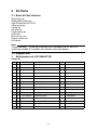
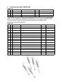
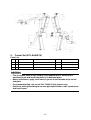
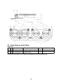
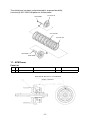
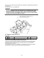
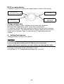
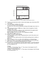
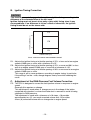
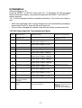
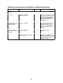
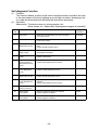
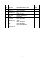
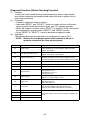
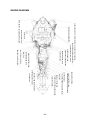
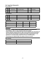
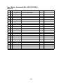
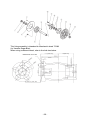
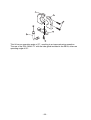
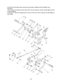
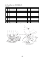
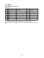
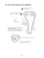
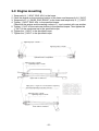
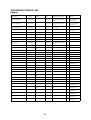
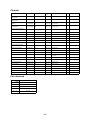
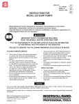
’04 YZF-R1
KIT MANUAL
The Performance Edge
for top-ranking riders
2004 YZF-R1 Kit Manual
Please note :
• It should be understood that these kit parts are not covered by warranty.
• The manufacturer does not assume any responsibility for problems caused by
these parts.
• These kit parts are intended for racing alone. They are not to be used in any
circumstances on public roads.
• The specifications and methods of use of these kit parts and the contents of the
present manual are subject to improvement changes without notice.
• This manual is intended for persons with knowledge and experience of
motorcycles. Please refer to the service manual for information on part assembly
and maintenance.
CONTENTS
1
2
Standard Specifications ...................................................................................1
Kit Parts .............................................................................................................2
2-1 Basic Kit Set Contents..............................................................................2
2-2 Engine Parts ..............................................................................................2
1.
Maintenance set (5VY-MAINT-70).......................................................2
2.
Spark Plugs ........................................................................................3
3.
AIS Plug Set (5VY-A4890-70) .............................................................3
4.
Gaskets...............................................................................................4
5.
High-lift Camshaft, Valve Spring ........................................................5
6.
Standard-lift Camshafts ....................................................................6
7.
Flat Valve Set (5VY-A2100-70)............................................................7
8.
Sub-radiator Set (5VY-A240A-70) ......................................................8
9.
Funnel Set (5VY-A4460-70) ...............................................................9
10. Clutch Spring, Clutch Boss .............................................................10
11. ACM Rotor .......................................................................................11
12. Engine Control Unit (ECU) ................................................................12
13. Wire Harness ...................................................................................23
14. Headlight Harness Set (5VY-F4350-70) ...........................................23
2-3 Chassis Parts ..........................................................................................25
15. Oil Catcher Tank Set (5VY-C1707-70) .............................................25
16. Chassis Protector Set (5VY-C117G-70) ...........................................26
17. Rear Suspension Spring...................................................................26
18. Front Fork Spring Set .......................................................................27
19. Front Disk Assembly (5VY-2581T-70) ..............................................28
20. Front Wheel Attachment Set ............................................................29
21. Rear Arm Attachment Set, Rear Wheel Attachment Set .................30
22. Sprocket, Sprocket Nut ....................................................................34
23. Throttle Set (5VY-C6300-70).............................................................34
24. Footrest Set (5VY-C7400-70)............................................................36
25. Front Stay Set (5VY-C8350-70) ........................................................38
2-4 Other.........................................................................................................39
26. Valve Seat Cutter Set........................................................................39
3
Installation Precautions ..................................................................................40
3-1 Checking the Valve Seats .......................................................................40
3-2 Selecting the crankshaft bearing...........................................................42
3-3 Selecting the connecting rod bearing ...................................................43
3-4 Installing the piston, piston ring and connecting rod ........................45
3-5 Crankcase installation ...........................................................................47
3-6 Cylinder head tightening (calibrated wrench tightening method)......48
3-7 Camshaft installation ..............................................................................49
3-8 Cam chain tensioner installation ...........................................................50
3-9 Engine mounting .....................................................................................51
3-10 Front axle installation .............................................................................52
Headlight cord wiring diagram .......................................................................56
2004 YZF-R1 Wiring Diagram..........................................................................57
1 Standard Specifications
Item
Standard
Displacement
998 cm3
Basic Kit
Bore/stroke
77,0 mm/53,6 mm
Primary reduction gear ratio 65/43 (1.512)
Compression ratio
Surface honing
12.4:1
-
13.3:1
0,45 mm
Squish height
0,75 mm
0,60 mm
Camshaft INT
Nominal
Major axis
5VY-00
292° – 7.6
32,9 mm
5VY-70
286 – 8.5
33,8 mm
Camshaft EXT
Nominal
Major axis
5VY-00
284° – 7.5
30,8 mm
5VY-70
288 – 8.5
31,8 mm
Valve timing (event angle)
INT
EXT
105°
105°
105°
105°
Valve clearance
INT
EXT
0,17 mm – 0,23 mm
0,27 mm – 0,33 mm
Throttle body
MIKUNI
Throttle valve passage diameter 45.0 mm
Exhaust system
4-2-1 type, #1-#2/#3-#4 connected
Transmission
1st
2nd
3rd
4th
5th
6th
Constant mesh 6-speed box
38/15 (2.533)
33/16 (2.063)
37/21 (1.762)
35/23 (1.522)
30/22 (1.364)
33/26 (1.269)
Clutch
Wet type, multiple disc
Ignition timing
DC-CDI
-1-
2
Kit Parts
2-1 Basic Kit Set Contents
Spark plug set
Head gasket (0.30 mm)
High lift camshaft (INT, EXT)
Valve spring set
Funnel set
AIS plug set
Clutch spring set
ACM rotor
Wire harness set
Engine control unit
Kit manual
Note:
The part marked [ * ] at the top of the parts list is included in the kit, but if it is
specifically needed, it is available from Yamaha authorized dealers.
2-2 Engine Parts
1. Maintenance set (5VY-MAINT-70)
Parts List
No.
PART No.
PART NAME
Q’TY
*
1
5VY-11181-00
GSKT., H/C
3
*
2
5VY-11351-00
GSKT, 1
3
*
3
5VY-11603-00
RING SET
12
*
4
5VY-1165A-01
BOLT, CON-ROD
12
*
5
90468-12069
CIRCLIP
12
*
6
4TV-12119-00
SEAL, STEM
36
INT
*
7
4SV-12119-00
SEAL, STEM
24
EXT
*
8
5VY-13414-00
GSKT, STRAINER
3
*
9
5VY-15451-00
GSKT COVER1
3
ACM
*
10
5VY-15461-00
GSKT COVER2
3
CLUTCH
*
11
5VY-15456-00
GSKT 1
3
PICK UP
*
12
5VY-15462-00
GSKT COVER3
3
BREATHER
*
13
90179-20007
NUT
3
CLUTCH BOSS
*
14
90215-30233
WASHER LOCK
3
SPROCKET
*
15
93102-40330
OIL SEAL
3
DRIVE AXLE
*
16
90110-06027
BOLT
9
MAIN AXLE
-2-
REMARKS
2.
Spark Plugs
Parts List
No.
PART No.
PART NAME
Q’TY
1
5 FL-94700-70
PLUG, SPARK
1
REMARKS
NGK R0045Q-10
Set No. : 5FL-R045Q-70 (R0045Q-10, 4 plugs)
CAUTION :
Since these spark plugs have a copper gasket, caution is needed during
installation on the following points.
1. The tightening torque is 1.0 – 1.2 kg·m.
2. When not checking the torque, tighten by rotating through only 30° after
manual tightening in the case of new plugs. When reusing plugs, tighten by
rotating through 15°.
Reused (15°)
New gasket
(30°)
3.
AIS Plug Set (5VY-A4890-70)
This plug set is used when the AIS (Air Induction System), an exhaust gas purifying
system, is removed.
Parts List
No.
PART No.
PART NAME
Q’TY
1
5SL-1482L-70
PLATE
2
*
2
93608-16M16
PIN
4
*
3
93306-10020
PLUG
1
REMARKS
Installation
1. Remove the hose attached to the cylinder head cover and the air cut-off valve
accompanying the hose.
2. Remove the cap fitted to the hose, remove the reed valve and plate from inside.
3. Install the plate (5SL-1482L-70) in replacement of the cap. Apply liquid gasket to
the plate.
4. Remove the cylinder head cover and the four collars fitted to the cover. Install the
PIN (93608-16M16).
5. After removing the hose connected to the air filter casing form the air cut-off
assembly, insert the PLUG (90336-10020) onto the side of the air filter casing to
close the opening.
-3-
REMOVE
4.
Gaskets
Parts List
No.
PART No.
PART NAME
Q’TY
REMARKS
1
5VY-11181-70
GASKET, HEADCYL.
1
t=0,30 mm
2
5VY-11181-80
GASKET, HEADCYL.
1
t=0,35 mm
3
5VY-11351-70
GASKET, CYL.
1
t=0,10 mm
4
5VY-11351-80
GASKET, CYL.
1
t=0,15 mm
These parts are used to adjust the squish height and compression ratio.
They should be installed in the direction, which enables the punched alpha-numeral
“5VY” to be visible.
The standard head cylinder gasket thickness is 0.40 mm and the cylinder gasket
thickness is 0.20 mm.
-4-
5.
High-lift Camshaft, Valve Spring
High-lift specification
No.
PART No.
PART NAME
Q’TY
1
5VY-12171-70
SHAFT, CAM 1
1
2
5VY-12181-70
SHAFT, CAM 2
1
REMARKS
90105-07003
5VY-12176-00
1
2
When using these camshafts, the valve springs should also be those in the kit.
Specification
Nominal
Working angle
Major Axis
286-8.5
286
33.8
288-8.5
288
31.8
Valve spring set (5VY-A2111-70)
No.
PART No.
PART NAME
Q’TY
REMARKS
1
5VY-12113-70
SPRG., 1
12
For 5VY-12171-70
2
5VY-12114-70
SPRG., 2
8
For 5VY-12181-70
The standard valve timing is 105° for both intake and exhaust valves.
-5-
To adjust the valve timing, use the oval holes of the standard cam sprocket.
USE THESE OVAL HOLES FOR TIMING ADJUSTMENT.
6.
Standard-lift Camshafts
Parts List
No.
PART No.
PART NAME
Q’TY
1
5VY-12171-80
SHAFT, CAM 1
1
2
5VY-12181-80
SHAFT, CAM 2
1
REMARKS
Specification
Nominal
Working angle
Major axis
288-7.9
288
32.9
288-7.8
288
30.8
The standard valve adjustment is 105° for both intake and exhaust valves.
For valve adjustment, use the oval holes in the standard cam sprocket.
USE THESE OVAL HOLES FOR TIMING ADJUSTMENT.
-6-
7.
Flat Valve Set (5VY-A2100-70)
Parts List
No.
PART No.
PART NAME
Q’TY
REMARKS
1
5VY-12111-70
VALVE, INTAKE
4
Centre of intake (L=87.16)
2
5VY-12112-70
VALVE, INTAKE 2
8
Side of intake (L=88.34)
3
5VY-12121-70
VALVE, EXT.
8
These valves are used to improve the compression ratio (about 0.2) by making their
shape on the compression chamber side flatter than in the case of standard valves.
They are made of steel and have the same weight as the standard ones.
Standard parts are the following:
Parts List
No.
PART No.
PART NAME
Q’TY
1
5VY-12111-00
VALVE, INTAKE
4
2
5VY-12112-00
VALVE, INTAKE
8
3
5VY-12121-00
VALVE, EXHAUST
8
4
5NL-12116-00
SEAT, VALVE SPRING
12
5
3GM-12126-00
SEAT, VALVE SPRING 2
8
6
5VY-12113-00
SPRING, VALVE INNER
12
7
5VY-12114-00
SPRING, VALVE OUTER
8
8
5VY-12117-00
RETAINER, VALVE SPRING
12
9
5VY-12127-00
RETAINER, VALVE SPRING
8
10
1HX-12118-00
COTTER, VALVE
24
11
1WG-12118-00
COTTER, VALVE
16
12
4TV-12119-00
SEAL, VALVE STEM
12
13
4SV-12119-00
SEAL, VALVE STEM
8
14
1HX-12168-
PAD, ADJUSTING 2
20
15
3LN-12153-
LIFTER, VALVE
12
16
3FV-12153-
LIFTER, VALVE
8
-7-
REMARKS
8.
Sub-radiator Set (5VY-A240A-70)
Parts List
No.
PART No.
1
5VY-1240A-70
RADIATOR ASS’Y
1
*
2
95817-06012
BOLT
1
*
3
90430-06014
GASKET
1
*
4
90480-15363
GROMMET
1
*
5
90387-0614M
COLLAR
1
*
6
95827-06030
BOLT
1
*
7
90201-06071
WASHER
1
8
5VY-12637-70
STAY
1
*
9
95807-06016
BOLT
2
*
10
5VY-12467-70
COVER, RADIATOR
1
11
90465-13275
CLAMP
3
12
5VY-12483-70
PIPE, 3
1
13
5VY-12579-70
HOSE, 4
1
14
90450-35001
HOSE CLAMP ASS’Y
6
15
5VY-1243F-70
HOSE, 3
1
16
5VY-12581-70
JOINT, HOSE 1
1
17
5VY-1244G-70
HOSE, 4
1
18
5VY-1244H-70
HOSE, 5
1
19
5VY-12589-70
HOSE, 6
1
20
90450-25037
HOSE CLAMP ASS’Y
1
*
*
PART NAME
Q’TY
REMARKS
CAUTION :
• This kit must not be installed on a muffler of competitive manufacture.
• The standard one should be used for the main radiator.
• Remove the cooling fan from the standard radiator.
• Do not fasten the hose clamp too tightly, otherwise the hose may become
distorted and start leaking.
• After installation, ensure that the radiator and the hose do not touch the
exhaust pipe.
• Air left in the water passage adversely affects cooling efficiency. To add
water, rock the motorcycle from side to side to remove air from the water
passages. After water has been added, let the engine idle, with the radiator
cap removed and add water to fill the space formed in the passage by the
escape of air. Lastly, tighten the cap.
-8-
9.
Funnel Set (5VY-A4460-70)
Parts List
No.
PART No.
PART NAME
Q’TY
REMARKS
5VY-14477-70
PLATE
2
5VY-14469-70
FUNNEL, 1
4
L=27 mm
5VY-14469-90
FUNNEL, 1
4
L=46 mm
CAUTION :
• The air cleaner case is kept fixed by the standard funnel. Remove this
standard funnel and install the plate in its destined place.
• Before installation, apply a thin coat of grease to the threads of the funnel
and plate.
• For standard setting, use funnel 5VY-14469-70 (the shorter one).
• Select the setting according to exhaust pipe specification, rider’s preference
and track layout.
-9-
INSTALL WITH THE MACHINED
SIDE DOWN.
10. Clutch Spring, Clutch Boss
Parts List
No.
PART No.
PART NAME
Q’TY
1
5VY-16334-70
SPRING, CLUTCH
6
2
5VY-16371-70
BOSS, CLUTCH
1
REMARKS
The clutch spring has a 10% better load capacity than the standard one.
- 10 -
The clutch boss has been surface-treated for improved durability.
Use nine (9) 5VY-16321-00 plates as friction plates.
5VY-16351-00
90159-06009
1
5VY-16325-00
5VY-16321-00
2
2
90179-20007
90208-20001
11. ACM Rotor
Parts List
No.
PART No.
1
5SL-81450-70
PART NAME
ROTOR
Q’TY
1
DIRECTION OF ONE-WAY CLUTCH ROTATION
INSTALL STD PARTS
- 11 -
REMARKS
This rotor is narrower than the standard rotor, aiming at a reduced inertia mass and
frictional load.
For the stator coil, use standard one.
CAUTION :
• The rotor and starter clutch are integrated. Use a standard starter clutch.
• After the installation of the starter clutch, check for direction of rotation.
• To install the stator coil-integrated cover, tighten the three (3) bolts (M8) to
22.0 Nm and the other bolts (M6) to 10.0 Nm.
AFTER TIGHTENING THE 3 M8 BOLTS TO 22 Nm,
TIGHTEN THE OTHER (M6) BOLTS.
12. Engine Control Unit (ECU)
Parts List
No.
PART No.
1
5VY-8591A-70
PART NAME
Q’TY
ECU
REMARKS
1
CAUTION concerning the basic motorcycle
The ECU kit cannot be used if the basic motorcycle conforms to the European
specification and if the part number of the main harness is 5VY-82590-00.
Use the harness from the kit.
A combination of harness “5VY-82590-10” intended for the USA and Australia
and the ECU kit can be used, but only for the ST (Stock Sports).
- 12 -
NOTE on meter display:
Connection of the ECU kit allows the standard meter to switch to the kit mode.
STD : Clock
Kit :
Max. Water Temp.
Retains Max. Temp. uring Run
STD : Water Temp.
Kit :
No Display
STD : ODO/TRIP Etc.
Kit :
Applicable Value
Adjusting Mode
STD : Speed
Kit :
Water Temp.
Air Temp. (Select)
Change of basic data
Use of the kit harness makes it possible for basic data to be selected for
SB (Super Bike) specification and ST (Stock Sports) specification.
For switching, use the white 2-pin connector located on the main switch connector
for the kit wire harness. The SB specification is available, when the connector with
a black lead is connected. When it is removed, the ST specification becomes
available.
A.
Setting Fuel Injection
Changes that may be made to fuel injection
CAUTION :
It is recommended that an A/F measuring instrument should be used
for this setting when checking the A/F figures on the instrument.
At high revolutions in particular, too lean a mixture may damage the engine.
The range of adjustment shown on the meter is ±25%.
As a guideline, a “1%” change effects a change of 0.1 in the A/F.
- 13 -
THE INJECTION VOLUME F5 TO F9 IS
ADJUSTED IN THE SAME WAY AS FOR F4.
F4 F5 F6 F7 F8 F9
THROTTLE OPENING (%)
90
F3
25
F2
F1
0
9000 10000 11000 12000 13000
3000
ENGINE SPEED (rpm)
RANGE OF ADJUSTMENT OF THE VOLUME OF INJECTION F1 TO F9
F0: Transfer to the adjustment mode is shown in the display area at the bottom RHS
of the meter.
F1: This mode helps to stabilize idle running.
Too rich an A/F may foul the spark plug.
Too lean an A/F may cause unstable idle running and the engine may come to a
stop.
F2: The engine speed range of 3000 rpm or higher can be changed at a throttle
opening of 25% or less.
A change in F2 produces an effect on “feel” experienced during engine brake
activation and at the start of throttle opening.
Make a change of 2 to 5% at a time, while checking any change.
The rough A/F target is 12 to 14.
F3: Range of 25 to 90% throttle opening.
This range affects the feel, which is experienced as a result of the initial to half
throttle opening.
Jump-out at the start and hesitation at half-throttle opening may be solved by a
leaner A/F.
Make a change of 2 to 5% at a time, while checking any resulting changes.
F4: Adjusts the volume of fuel injected at any engine speed at a throttle opening of
90% or more. This mode constitutes the basic F5 to F9 data.
F5 to F9: Adjust the volume injected at individual engine speeds, at a throttle opening
of 90% or more, but note that the adjusted values in these modes are based on
the value adjusted in F4.
Example
Let F5 be “+3” after letting F4 be “+3”. The volume of fuel injected in the F5
range will be represented by “+6”.
Let F8 be “–6” after letting F4 be “+2”. The volume of fuel injected in the F8 range
will be represented by “–4”.
- 14 -
B.
Ignition Timing Correction
CAUTION :
This function corrects the gaps for the optimum ignition timing according to the
difference of the characteristics of the fuel used.
Ignition timing must not be set at too early a (plus side) timing since it may
cause problems. If no difference is felt as a result of correction, the ignition
timing should be set on the slower side.
FC
THROTTLE OPENING (%)
90
FB
25
FA
0
3000
ENGINE SPEED (rpm)
FA-FC: IGNITION TIMING ADJUSTMENT RANGE
FA: Adjusts the ignition timing at a throttle opening of 25% or less and at an engine
speed of 3000 rpm or more, with a tolerance of ±15°.
FB: Adjusts the ignition timing at a throttle opening of 25% or more and 90% or less
and at an engine speed of 3000 rpm or more with a tolerance of ±10°.
FC: Adjusts the ignition timing at a throttle opening of 90% or more and at an engine
speed of 3000 rpm or more.
This range is apt to cause problems, according to engine tuning. In particular,
if the setting is on the + side, change degrees one by one while checking the
result.
C.
Adjustment of the RAM-Pressure Fuel Volume Correction
FD: This ECU is designed to correct the fuel injection volume in response to engine
speed.
Generally this requires no change.
This adjustment is made when a change occurs in the shape of the intake
compared with standard, or when the intake duct is removed to avoid its being
subjected to RAM pressure.
The adjustment is made with a tolerance of ±10 steps; +10 provides
approximately two (2) x as much corrected volume and –10 provides
a zero (0) corrected volume with no change due to engine speed.
- 15 -
Procedure (fuel adjustment, ignition timing correction, and
adjustment of RAM-pressure fuel correction volume)
1.
2.
3.
4.
5.
D.
Transfer to F0 mode
Keeping both the “SELECT” and “RESET” buttons pressed simultaneously, turn
on the main switch.
“F0 ” appears in the display area at the bottom RHS of the meter.
Transfer to the ECU applicable mode
Keeping both the SELECT and RESET buttons pressed simultaneously. “F1”
appears in the display.
Selecting and confirming the applicable mode
When the SELECT or RESET buttons are simultaneously pressed, the display
shows the next application or reverts to the previous mode.
Keeping them pressed down allows the display to go step by step to the next
mode or to revert to the previous mode.
F1⇔F2⇔F3⇔F4⇔F5⇔F6⇔F7⇔F8⇔F9⇔FA⇔FB⇔FC⇔FD⇔FE⇔F1
When the mode you want to change appears, simultaneously press the SELECT
and RESET buttons in order to conform the desired mode.
Changing and confirming the applicable value
When confirmation is made, “FX_YY” appears in the display.
YY indicates the applicable value and “ 0” the standard value.
For fuel volume correction, % is shown and for ignition timing correction, the
timing angle is shown.
To change the “YY” value, press the SELECT or RESET buttons and change the
numerical value.
To confirm the changed value and to transfer to another mode, simultaneously
press the SELECT and RESET buttons.
The value “YY” disappears from the display area in preparation for the
adjustment mode to be switched.
Finishing the adjustment mode
Turn off the main switch, and the adjustment mode will end.
Initialization of Value Changed
FE: Keeping the SELECT and RESET buttons simultaneously pressed, the transition
to this mode brings about initialisation.
“FE_YY” is shown in the meter screen. The numerical value “YY” represents the
value of each of the 13 modes from F1 to FD, but since it does not indicate which
mode has been changed, it is necessary to transfer to the adjustment mode in
order to check.
If “ 0” is displayed, it indicates an absence of changes and no initialisation is
needed. Turn off the main switch to end
- 16 -
Initialization
(Bring all settings to “0”.)
Press the “RESET” or “SELECT” button with “FE_YY” displayed. “FE_88” will appear.
While checking this display, simultaneously keep both the “RESET” and “SELECT”
buttons pressed.
“FE_ 0” will be displayed and this completes initialisation. Turn off the main switch to
end.
• While each applicable value is being changed, the value immediately preceding is
memorised in the ECU, even with the main switch off.
• The set values changed are retained, even after the battery has been removed.
<EFI Fuel Amount/Ignition Timing Adjustment Mode>
Select
code No. Adjustment item
Adjustment range
Adjustment range/Remarks
F0
Adjustment mode for kit
applicable value
Display at selection and transfer
to diagnostic mode
F1
Adjustment of fuel volume
Throttle opening of 25% or less
Engine speed of 3000 rpm or less
Adjustment range [±25%]
F2
Adjustment of fuel volume
Throttle opening of 25% or less
Engine speed of 3000 rpm or more
Adjustment range [±25%]
F3
Adjustment of fuel volume
Throttle opening of 25 to 90%
Adjustment range [±25%]
F4
Adjustment of fuel volume
Throttle opening of 90% or more
Adjustment range [±25%]
F5
Adjustment of fuel volume
Throttle opening of 90% or more
Engine speed of 9000 to 10000 rpm
Adjustment range [±25%]
F6
Adjustment of fuel amount Throttle opening of 90% or more
Engine speed of 10000 to 11000 rpm
Adjustment range [±25%]
F7
Adjustment of fuel amount Throttle opening of 90% or more
Engine speed of 11000 to 12000 rpm
Adjustment range [±25%]
F8
Adjustment of fuel amount Throttle opening of 90% or more
Engine speed of 12000 to 13000 rpm
Adjustment range [±25%]
F9
Adjustment of fuel amount Throttle opening of 90% or more
Engine speed of 13000 rpm or more
Adjustment range [±25%]
FA
Ignition timing correction
Throttle opening of 25% or less
Engine speed of 3000 rpm or more
Adjustment range [±15 deg.]
FB
Ignition timing correction
Throttle opening of 25 to 90%
Engine speed of 3000 rpm or more
Adjustment range [±10 deg.]
FC
Ignition timing correction
Throttle opening of 90% or more
Engine speed of 3000 rpm or more
Adjustment range [±5 deg.]
FD
Adjustment of RAM
pressure fuel volume
correction
Correct according to vehicle speed.
Adjustment range [±10 steps]
FE
Initialisation of adjustment
volume
Number of changes in adjustment value,
along with initialisation
For change, “total number of
changes in adjustment value” is
displayed.
Initialisation mode “88” for
compatible value is displayed.
- 17 -
<Operation Procedure for F1 to FD Fuel Amount/Ignition Timing
Adjustment>
Operation
Meter display Significance
a Mode
Transfer Keep "RESET" + "SELECT"
simultaneously pressed and turn on
"MAIN SWITCH".
[______]
➔
Item
[F0____]
c Check for ECU Applicable Keep "RESET" + "SELECT"
Mode
simultaneously pressed
[F1____]
d Select ECU Applicable
item
Each time "SELECT" is pressed, the
selection code is added
[F2____]
➔
“F1➔F2➔F3 • • • FD➔FE➔F1 • • •”
Sequential selection of F1 to FE
F1 follows FE and again from F1 to
FE
Each time "RESET" is pressed, the
selection code is subtracted.
[F1____]
“F1➔FE➔FD • • • F2➔F1➔FE • • •”
➔
b ECU Applicable Value
Adjustment/Diagnostic
Function
➔
f Change in Adjustment
Volume
Each time "SELECT" is pressed,
the adjustment value is increased.
[F1___1]
Each time "RESET" is pressed, the
adjustment value is decreased.
[F1___0]
➔
Turn off "MAIN SWITCH".
➔
h Finish Changing the
Applicable Value
➔
[F1___0]
Keep "RESET" + "SELECT"
simultaneously pressed.
Selective state of Code F1
(at Ne-3000 rpm or less/Th-25% or
less) * Always starts from F1.
➔
e Check for Applicable Item Keep "RESET" + "SELECT"
(F1 to FD)
simultaneously pressed.
g Select Other Items
"F0" indicates ECU applicable value
Adjustment mode.
[F1____]
Current injection correction (0%)
appears in the lower area of LC.
Adjustable state of Code F1
(at Ne-3000 rpm or less and
Th-25% or less)
“F1___1➔2➔3 • • •
(Max. + 25%)
* Refer to adjustment range.
“F1___0➔ –1➔ –2➔ –3 • • • –25”
(Max. -25%) * Refer to adjustment
range.
When "RESET" or "SELECT" is
pressed, the correction volume is
changed and at the same time it is
memorised in ECU.
Adjustment amount display goes out,
followed by the selective state for an
applicable item.
The rest of the procedure is the same
as above.
"MAIN SWITCH" can be turned off at
any timing above.
- 18 -
<Operation Procedure for Initialization of Adjustment Values>
Item
Operation
Meter display Significance
(Items and their operating procedures are the same as <Operating procedure for F1 to FD fuel volume/ignition timing
adjustment>
[FE___*]
Number of changes in adjustment
values for F1 to FD appears in lower
figure place in LC: Mode for checking
the number of adjustment values to
be operated. Holding "RESET" and
"SELECT" simultaneously pressed
allows transfer to Select ECU
applicable item.
j Check number of
adjustment values to be
operated/initialise
adjustment value.
Switch is possible by pressing
"SELECT" or "RESET".
[FE__88]
"88" appears in lower-figure place in
LC: Initialisation mode for adjustment
value Pressing "SELECT" or
"RESET" alternately changes the
mode either for checking the number
of values to be operated, or for
initialisation.
k Initialisation of Changed
Adjustment Values
(Initialisation mode being
selected)
Keep "RESET" and "SELECT"
simultaneously pressed.
(for 2 sec. or more)
[FE___0]
l Initialisation ends
After ceasing the simultaneous
pressing of "RESET" and "SELECT",
repeat the process
[FE____]
➔
- 19 -
➔
i Determine Applicable item After selecting FE in above, keep
(Code FE)
"RESET" and "SELECT"
simultaneously pressed.
The lower area of LC displays (0) to
indicate the completion of
initialisation.
Enter the state for selecting Code FE
(adjustment value management).
The rest of the procedure is the same
as the above, and the selection mode
for ECU applicable items starts with
"SELECT" or "RESET".
Self-diagnosis Function
(1)
Function
This function detects a failure in the sensor and the actuator and alerts the user
to the occurrence of failure by lighting up a pilot light on meter / displaying a failure code and simultaneously launching the evacuation procedure.
Operation
Abnormality: The alarm comes on (during engine run),
Alarm comes on + Abnormality code appears (engine at standstill)
(2)
Failure
code
Item
Major cause of failure
11
Cam sensor
• Break/short circuit between cam sensor and ECU
• Cam sensor failure
12
Crank sensor
• Interruption/short circuit between crank sensor and ECU Not possible
• Crank sensor failure
13
Intake sensor
(broken/short circuit)
• Break/short circuit between intake pressure sensor and
ECU
• Failure of intake pressure sensor
14
Intake sensor (failure of • Failure of intake pressure sensor piping system
piping system)
(misaligned, interrupted)
Possible
15
TPS (broken/short
circuit)
• Break/short circuit between TPS and ECU
• Failure of TPS sensor
Possible
20
Failure of intake
pressure sensor or
atmospheric pressure
sensor
• Intake pressure sensor failure
• Failure of atmospheric pressure sensor
Possible
21
Water temperature
sensor (break/short
circuit)
• Break/short circuit between water temp. sensor and ECU Possible
• Failure of water temperature sensor
22
Intake temp. sensor
(broken/short circuit)
• Break/short circuit between intake temp. sensor and ECU Possible
• Failure of intake temperature sensor
23
Atmospheric pressure
sensor (broken/short
circuit)
• Break/short circuit between atmospheric pressure sensor Possible
and ECU
• Failure of atmospheric pressure sensor
30
Overturn sensor
(check for overturn.)
• Overturn sensor detects state of overturn.
Not possible
33
Ignition failure
of #1 cylinder
• Broken line between ignition coil and ECU
• Failure in ignition coil interior
Possible
34
Ignition failure
of #2 cylinder
• Broken line between ignition coil and ECU
• Failure in ignition coil interior
Possible
- 20 -
Engine
operation
Not possible
Possible
Failure
code
Item
Major cause of failure
35
Ignition failure
of #3 cylinder
• Broken line between ignition coil and ECU
• Failure in ignition coil interior
Possible
36
Ignition failure
of #4 cylinder
• Broken line between ignition coil and ECU
• Failure in ignition coil interior
Possible
41
Overturn sensor
(broken/short circuit)
• Wire broken/short circuit between overturn sensor and
ECU
• Overturn sensor failure
Possible
43
Failure of fuel system
power (monitor
voltage)
• Wire broken/short circuit between main relay and ECU
• Broken ECU voltage monitor wire
• Main relay failure
Possible
46
Abnormal power for
vehicle system
• Failure of charging system
• Failure in ACM or regulator
Possible
47
Sub-throttle sensor
(broken/short circuit)
• Broken/short circuited line between sub-throttle sensor
and ECU
• Failure in sub-throttle sensor
Possible
48
Sub-throttle motor
(stuck)
• Broken/shorted line between sub-throttle motor and ECU Possible
• Failure of sub-throttle motor
• Failure of sub-throttle mechanism
50
ECU interior failure
(abnormal ROM data)
• ECU interior data error
- 21 -
Engine
operation
Impossible
Diagnosis Function (Status Checking Function)
(1)
(2)
(3)
Function
To help users with troubleshooting and maintenance, sensor output display
and actuator operation are made possible without the use of special tools or
measuring instruments.
Procedure
• Transfer to diagnostic mode as follows:
• Hold down "RESET" and "SELECT" buttons on meter and turn on the main
switch. Continue holding the buttons down, until "F0" appears on meter.
• When "F0" appears on meter, press "SELECT" to switch to "DIAG" and confirm
by simultaneously pressing down "SELECT" and "RESET" buttons.
• Using "RESET" or "SELECT", switch to destination diagnostic code.
Operation
The following describes the operation of each diagnostic code in ECU.
* NOTE: Remove the fuel pump coupler while codes 36 to 39 are in
operation to prevent fuel from being injected.
Code selected Item
Description
01
Throttle sensor
• Displays throttle sensor input value in angle.
• Fully closed throttle "15 to 18" degrees, fully open throttle
approx. "95" degrees.
02
Atmospheric pressure sensor
• Displays atmospheric pressure in Kpa.
• Approx. "101" Kpa at normal altitudes.
03
Intake pressure sensor
• Displays intake vacuum in Kpa.
• Displays atmospheric pressure when crankshaft is at rest.
• Less than atmospheric pressure during starting motor cranking.
05
Intake temp. sensor
• Displays sensor-detected temp. in °C.
06
Water temp. sensor
• Displays sensor-detected temp. in °C.
07
Vehicle speed sensor
• Displays integrating number of sensor detected pulses.
08
Overturn sensor
• Displays sensor output voltage.
Erected "0.4 to 1.4" V
Overturned "3.7 to 4.4" V
Line broken "5.0" V
09
Monitor voltage
• Displays battery voltage when engine switch is turned on.
• Approx. "12" V when engine is at rest.
20
Shifter switch
• Displays state of speed shift switch in ON/OFF.
ON: Shift switch is on.
OFF: Shift switch is off.
21
Select switch
• Displays state of select switch in ON/OFF.
ON: SB (selects MAP in Super Bike specification.)
OFF: ST (selects MAP in Stock Sports specification.)
30
Ignition coil #1
31
Ignition coil #2
32
Ignition coil #3
33
Ignition coil #4
• Turning the engine switch off and on activates the ignition coil 5
times.
- 22 -
Code selected Item
Description
36
Injector #1
37
Injector #2
38
Injector #3
39
Injector #4
50
Main relay
• Turning the engine switch off and on activates main relay 5 times.
53
EXUP
• Turning the engine switch off and on activates EXUP motor from
fully open to fully closed throttle.
56
Sub-throttle
• Turning the engine switch off and on activates the sub-throttle motor
from fully open to fully closed throttle.
60
No function
61
No function
62
No function
70
Management No.
• Turning the engine switch off and on activates the injector 5 times.
13. Wire Harness
Parts List
No.
PART No.
1
5VY-82590-70-0
2
5FL-83976-70
PART NAME
Q’TY
WIRE HARNESS ASSY.
1
SWITCH ASSY.
1
REMARKS
This harness is designed to be lighter than standard for sprint racing.
The switch accompanying the assembly, functions as the main switch.
Even if the main switch is "OFF", the meter backup power is "ON". Before storing the
motorcycle for 3 month or longer, remove the negative terminal from the battery.
For wiring, see the "WIRING DIAGRAM".
14. Headlight Harness Set (5VY-F4350-70)
Parts List
No.
PART No.
PART NAME
Q’TY
1
5VY-84350-70
CORD, HEAD LIGHT
1
*
2
5JJ-81950-20
RELAY
2
*
3
5GF-83976-00
SWITCH, HANDLE
REMARKS
This set is used in endurance races in combination with the kit harness for turning on
the STD headlights and taillights.
It assumes that the standard headlights and taillights are used.
The 2-system circuit is provided to allow the other bulb to light up when one is broken.
The headlight and taillight circuits are independent of one another. If the headlight is
broken, the taillight will not go out.
For wiring, see the "WIRING DIAGRAM".
- 23 -
WIRING DIAGRAM
ENGINE KILL SWITCH LEAD
OIL LEVEL GAUGE LEAD
ACM LEAD
STARTER MOTOR LEAD
NEGATIVE BATTERY LEAD
FUEL PUMP LEAD
ENGINE GROUND LEAD
CRANKSHAFT SENSOR LEAD
SPEED SENSOR LEAD
HANDLEBAR SWITCH (RIGHT)
HEADLIGHT HARNESS CONNECTOR
HANDLEBAR SWITCH (RIGHT), METER LEAD, HEADLIGHT HARNESS
IGNITION COIL CONNECTOR
ECU
EXUP LEAD
THROTTLE BODY LEAD
MAIN SWITCH, SELECTOR SWITCH LEAD
HEADLIGHT HARNESS
POSITIVE BATTERY LEAD
PASS ON INSIDE OF BATTERY BAND
FUSE BOX (REMOVE FLASHER RELAY)
STARTER RELAY
MAIN FUSE
ATMOSPHERIC PRESSURE SENSOR
ENGINE STOP SWITCH
HEADLIGHT CORD
EXTERNAL POWER CONNECTOR
STARTING SAFETY RELAY
TAILLIGHT UNIT
- 24 -
2-3 Chassis Parts
15. Oil Catcher Tank Set (5VY-C1707-70)
Parts List
Q’TY
REMARKS
CATCH TANK COMP.
1
Capacity: 630 cc
5EB-15373-70
HOSE
2
3
90450-25037
HOSE CLAMP ASS'Y
6
4
5SL-11166-70
PIPE, BREATHER 1
1
5
371-11167-01
PIPE, BREATHER 1
1
*
6
4XV-21376-00
BAND
2
*
7
90464-08002
CLAMP
1
*
No.
PART No.
1
5VY-21707-70
2
PART NAME
PASS UNDER TANK STAY
- 25 -
16. Chasis Protector Set (5VY-C117G-70)
Parts List
No.
PART No.
PART NAME
Q’TY
1
5VY-2117G-70
PROTECTOR
2
2
5SL-21472-70
COLLAR, PROTECTOR LH.
1
3
5SL-21477-70
COLLAR, PROTECTOR RH.
1
*
4
91317-10070
BOLT, HEX. SOCKET
2
*
5
90201-105R9
WASHER
2
REMARKS
FWD
FRAME
FRAME
ENGINE
RIGHT
LEFT
Remove the bolt holding the head and using the bolt supplied, install the chassis
protector and cut the cowling to fit the vehicle.
17. Rear Suspension Spring
Parts List
No.
PART No.
1
5VY-22212-70
PART NAME
Q’TY
SPRING, 1
REMARKS
K=9.0 kgf/mm
This spring is intended for use in the standard shock absorber.
Specification
KIT
STD
Free length
174 mm
174 mm
Spring rate
9,0 kgf/mm
8,5 kgf/mm
External colour
Yellow
Silver
- 26 -
18. Front Fork Spring Set
5VY-1244H-70
No.
PART No.
1
5VY-23141-70
*
2
*
3
PART NAME
Q’TY
REMARKS
FR. FORK SPRING
2
0,95 kgf/mm
5PW-23118-00
SPACER
2
4XV-23142-00
SEAT, SPRG UPPER
2
5VY-C3141-80
No.
PART No.
1
5VY-23141-80
*
2
*
3
PART NAME
Q’TY
REMARKS
FR. FORK SPRING
2
1,00 kgf/mm
5PW-23118-00
SPACER
2
4XV-23142-00
SEAT, SPRG UPPER
2
Specification
–70
–80
STD
Free length
255 mm
255 mm
236 mm
Spring rate
0,95 kgf/mm
1,00 kgf/mm
0,90 kgf/mm
No. of ID lines
1
2
Nil
CAUTION :
• The spring is longer overall than standard, because of its specification.
For setting up, use the collar supplied instead of standard.
• The pre-load is set to provide 0 mm with the fork assembly fully extended and
with the adjuster projecting 19 mm. When the front forks are free from load
other than their own weight, the apparent pre-load is approximately 7 mm,
because the rebound spring keeps the fork from rebounding fully.
• The spring rate is identified by the number of lines on its end.
Basic setting
Initial adjuster
14 mm (up to top end)
Oil level
76 mm (when compressed as far as possible)
Suspension oil
Yamaha Suspension Oil 01
- 27 -
5VY-23111-00
3XJ-23147-L0
3XC-23357-00
2
3
1
19. Front Disk Assembly (5VY-2581T-70)
Parts List
No.
PART No.
PART NAME
Q’TY
1
5VY-2582T-70
DISK, BRAKE Fr.
1
2
5VY-25832-70
BRACKET, DISK
1
3
5EB-2581M-70
PIN, FLOATING
10
4
5EB-2581N-70
WASHER
10
*
5
93430-09052
CIRCLIP
10
*
6
90109-064G6
BOLT
6
REMARKS
t=5,0
1
3
5
4
2
This assembly is of the fully floating type, with the outer rotor 5 mm thick for improved
durability when racing.
- 28 -
20. Front Wheel Attachment Set
This fixing assembly is intended for the TZ250 Marchesini wheel.
TZ250 MARCHESINI WHEEL
- 29 -
21. Rear Arm Attachment Set, Rear Wheel Attachment Set
Rear Arm Attachment Set (5VY-C2170-70)
Parts List
*
*
No.
PART No.
PART NAME
Q’TY
1
5VY-25388-70
PULLER 1
1
2
95317-20700
NUT
1
3
99009-32500
CIRCLIP
1
4
4FN-25322-70
INSERT, SHAFT
1
5
90110-06142
BOLT
1
6
4XV-25379-70
BOLT, PULLER
2
7
5VY-25389-70-0
PULLER 2
1
8
4XV-25381-70
AXLE, WHEEL Rr.
1
9
4XV-2580W-70
CALIPER ASSY.
1
10
4XV-25911-70
PAD LINNING COMP.
2
11
4XV-25379-70
BOLT, CHAIN PULLER
2
REMARKS
The rear arm attachment set includes a rear wheel fixing assembly to cover one
wheel.
No special rear sprocket is included in the rear arm fixing assembly or in the rear
wheel fixing assembly.
- 30 -
When using this set, it is necessary to reduce the length of the rear arm by 5 mm
since contact is made between the rear arm and puller 2.
SCRAPE AWAY
If a more competitive system is desired, with a rear arm for endurance racing, please
contact the following company:
MG Competition
ZAE LA FORET N° 108
74130 CONTAMINE/ARVE-FRANCE
TEL: +33 (0) 450 255 996
FAX: +33 (0) 450 255 998
E-mail : [email protected]
or
[email protected]
- 31 -
Rear Wheel Attachment Set (4XV-C5310-80)
Parts List
No.
PART No.
1
4XV-25767-70
COLLAR, DISK BRAKE
1
2
5FL-93307-70
BEARING
4
3
4XV-25317-80
SPACER, BEARING
1
4
4XV-2582V-80
DISK, BRAKE
1
5
91317-08025
BOLT
3
6
4XV-25832-80
BRACKET, DISK
1
*
7
90149-06286
SCREW
3
*
8
90185-06122
NUT
3
9
4XV-25683-80
SPACER
1
10
4FN-25366-70
CLUTCH, HUB
1
11
4XV-2539F-70
PLATE
1
*
12
91317-10025
BOLT
5
*
13
90185-10037
NUT
5
14
4XV-25376-80
COLLAR, SPROCKET
1
15
4FN-25441-70
Rr. SPROCKET 41T
16
5FL-93306-70
BEARING
4FN-25442-70
Rr. SPROCKET 42T
SIZE 520
4FN-25443-70
Rr. SPROCKET 43T
SIZE 520
4FN-25444-70
Rr. SPROCKET 44T
SIZE 520
4FN-25445-70
Rr. SPROCKET 45T
SIZE 520
4FN-25446-70
Rr. SPROCKET 46T
SIZE 520
*
PART NAME
Q’TY
REMARKS
SIZE 520
1
- 32 -
This fixing assembly is intended for Marchesini wheel 72186
(for Yamaha Super Bike).
When using a different wheel, refer to the hub size below.
(chain line)
DAMPER Marchesini 4031
- 33 -
(disk line)
22. Sprocket, Sprocket Nut
Parts List
No.
PART No.
1
4XV-17460-75
2
PART NAME
Q’TY
REMARKS
SPROCKET, DRIVE
1
15T, 520SIZE
4XV-17460-76
SPROCKET, DRIVE
1
16T, 520SIZE
3
4XV-17460-77
SPROCKET, DRIVE
1
17T, 520SIZE
4
4XV-17463-70
NUT, SPROCKET
1
FOR KIT SPROCKETS
5
4XV-25441-70
Rr. SPROCKET 41T
FOR STD WHEEL 520SIZE
6
4XV-25442-70
Rr. SPROCKET 42T
FOR STD WHEEL 520SIZE
7
4XV-25443-70
Rr. SPROCKET 43T
FOR STD WHEEL 520SIZE
8
4XV-25444-70
Rr. SPROCKET 44T
FOR STD WHEEL 520SIZE
9
4XV-25445-70
Rr. SPROCKET 45T
FOR STD WHEEL 520SIZE
10
4XV-25446-70
Rr. SPROCKET 46T
FOR STD WHEEL 520SIZE
11
4XV-25447-70
Rr. SPROCKET 47T
FOR STD WHEEL 520SIZE
When using the drive sprocket from the kit, use the sprocket nuts provided in that unit.
If standard nuts are used, use three (3) stacked spring washers.
23. Throttle Set (5VY-C6300-70)
Parts List
No.
PART No.
PART NAME
1
5EB-26281-81
CAP, GRIP UPPER
1
2
5EB-26282-81
CAP, GRIP LOWER
1
3
5FL-26391-80
CLIP, THROTTLE WIRE
1
4
5VY-26302-70
THROTTLE WIRE ASSY.
1
5
5FL-26243-71
TUBE, GUIDE
1
6
4YR-26242-00
GRIP 2
1
7
90201-261L1
WASHER
1
8
91317-05020
BOLT
2
9
91317-05014
BOLT
1
- 34 -
Q’TY
REMARKS
WHITE
1
2
5
3
4
6
This kit has an operation angle of 57°, resulting in an improved racing operation.
The use of the "5SL-26243-71" with the tube guide included in the R6 kit, allows an
operating angle of 52°.
- 35 -
24. Footrest Set (5VY-C7400-70)
Parts List
No.
PART No.
1
5SL-27412-70
BRKT., 1
1
2
5VY-27452-70
BRKT., FOOTREST 1
1
*
3
90151-08022
SCREW
4
*
4
90109-085G6
BOLT
4
*
5
4JT-27411-20
FOOTREST 1
2
*
6
97007-06020
BOLT
2
*
7
92907-06600
WASHER, PLATE
2
*
8
5FL-27445-00
PLATE 1
1
*
9
92017-06012
BOLT, BUTTON HEAD
2
10
5PW-18111-71
PEDAL, SHIFT
1
11
5EB-18162-70
PEDAL, FRONT
2
12
98707-06020
SCREW, FLAT HEAD
2
13
5VY-18112-70
ARM, SHIFT
1
*
14
95824-06020
BOLT, FLANGE
1
*
15
92017-06020
BOLT, BUTTON HEAD
5
16
5VY-18115-70
ROD, SHIFT
1
*
17
3TC-18116-00
JT., ROD 1
1
*
18
95304-06700
NUT
1
*
19
3TC-18117-00
JT., ROD 2
1
*
20
90170-06228
NUT
1
*
21
92017-06025
BOLT, BUTTON HEAD
1
*
22
95607-06100
NUT, U
2
23
5VY-27422-70
BRKT., 2
1
24
5VY-27462-70
BRKT., FOOTREST 2
1
25
5SL-27446-00
PLATE 2
1
26
5SL-2745A-71
COLLAR
4
27
5VY-2741L-70
BRKT., 4
1
28
5EB-27211-70
PEDAL, BRAKE
1
*
29
5SL-27853-71
SHAFT, PEDAL 1
1
*
30
95307-08700
NUT
1
*
31
92907-06200
WASHER, PLAIN
1
32
91401-16012
PIN, SPRIT
1
*
33
5EB-27456-70
SPRING, RETURN
1
*
34
92017-08030
BOLT, BUTTON HEAD
2
*
35
95307-08700
NUT
2
*
*
PART NAME
- 36 -
Q’TY
REMARKS
Install the rear brake return spring to the master cylinder with the rubber boot
removed.
This footrest is located on the lower side 5 mm to the rear, at the same height as that
of the standard.
A change of 10 mm in height and of 5 mm to the rear of this location can be made for
each step.
- 37 -
25. Front Stay Set (5VY-C8350-70)
Parts List
No.
PART No.
PART NAME
Q’TY
1
5VY-28356-70
STAY, 1
1
*
2
5VY-83519-70
BRACKET, METER
1
*
3
90149-06298
SCREW
2
*
4
95707-06500
NUT
4
*
5
4XV-83513-00
DAMPER
7
*
6
5VY-28321-70
STAY 1
1
*
7
5VY-28322-70
STAY 2
1
8
95807-06040
BOLT
2
*
9
5PW-28386-00
HEAD
2
*
10
5PW-2177L-00
PLATE, SPRING
2
11
90201-08008
WASHER
2
Use standard parts except for those supplied.
USE STD PARTS
- 38 -
REMARKS
2-4 Other
26. Valve Seat Cutter Set
Parts List
No.
PART No.
PART NAME
Q’TY
REMARKS
1
5SL-92110-70
CUTTER, INT 1
1
27.0 × 60°
2
5SL-92110-80
CUTTER, INT 2
1
27.0 × 90°
3
5SL-92110-90
CUTTER, INT 3
1
27.0 × 120°
4
5SL-92120-70
CUTTER, EXT 1
1
25.0 × 60°
5
5SL-92120-80
CUTTER, EXT 2
1
25.0 × 90°
6
5SL-92120-90
CUTTER, EXT 3
1
25.0 × 120°
7
5SL-92101-70
SPINDLE
1
4,0 mm
8
5VY-92101-70
SPINDLE
1
4,5 mm
This cutter set includes the same parts as for the 03 R6, but when using them for the
R1, reverse the respective names and locations for intake and exhaust.
The set includes an addition type of spindle in contrast with the assembly for the 03
R6.
- 39 -
3
Installation
Precautions
NOTE:
Please check next point for setting up
your motorcycle.
3-1 Checking the Valve
Seats
The following procedure applies to all
valves and valve seats.
1. Eliminate :
• lcarbon deposits (from the valve face
and valve seat)
2. Check :
• lvalve seat
Pitting/wear ➔ replace cylinder
head.
3. Measure :
• lMeasure the width of the valve seat (a)
Non-compliance with specification ➔
replace cylinder head.
Valve seat width
0,9 – 1,1 mm
(0.0354 - 0.0433 in)
<Limit>: 1.6 mm (0.06 in)
a.
b.
c.
d.
Apply mechanic's blue (Dykem) (b)
on the valve face.
Install the valve in the cylinder head.
Push the valve through the valve
guide and on the valve seat, to make
a clear impression.
Measure the width of the valve seat.
NOTE:
Where the valve seat and valve face
were in contact with one another, the
blue deposit will have been removed.
- 40 -
4. Lap :
• lvalve face
• lvalve seat
NOTE:
After replacing the cylinder head or
the valve and the valve guide, the
valve seat and valve face should be
lapped.
a. Apply a coarse lapping compound (a)
to the valve face.
CAUTION :
Do not let the lapping compound enter
the gap between the valve stem and
the valve guide.
b. Apply molybdenum disulfide oil on the
valve stem.
c. Install the valve in the cylinder head.
d. Rotate the valve, until the valve face
and valve seat are evenly polished,
then clean off all lapping compound.
NOTE:
For best lapping results, lightly tap the
valve seat while rotating the valve
back and forth between your hands.
e. Apply a fine lapping compound to the
valve face and repeat the above steps.
f. After every lapping cycle, clean off all
lapping compound from the valve face
and valve seat.
g. Apply mechanic's blue (Dykem) (b) on
the valve face.
h. Install the valve in the cylinder head.
i. Push the valve through the valve guide
and on the valve seat, to make a clear
impression.
j. Measure the width (c) of the valve seat
again. If the width is off specification,
reface and lap the valve seat.
- 41 -
3-2 Selecting the crankshaft bearing
1. Read the crank journal size.
2. Read the crankcase journal size.
(Read the size number on the rear wall of the engine mount boss on the lower casing)
3. (Casing size number) - (Crank journal size number) - 1
= (Bearing size number)
5 (Yellow) 5VY-11416-40
4 (Green) 5VY-11416-30
3 (Brown) 5VY-11415-20
2 (Black)
5VY-11416-10
1 (Blue)
5VY-11416-00
0 (White)
5VY-11416-A0
CAUTION :
Before installing the bearing, apply oil to its surface.
- 42 -
3-3 Selecting the connecting rod bearing
1. Read the crank pin size. (Look at web 1 of the crankshaft.)
2. Read the big end size of the connecting rod (stamped on the connecting rod cap).
3. Selecting the connecting rod bearing
(Big end size number) - (Crank pin size number) = (Bearing size number)
4 (Green) 5VY-11656-30
3 (Brown) 5VY-11656-20
2 (Black)
5VY-11656-10
1 (Blue)
5VY-11656-00
CAUTION :
Use the same weight management symbol (alphabetical letter) for all four
connecting rods.
Install with mark Y on the left
Apply oil.
Sign for selection of big end hole diameter
Weight management sign
- 43 -
Connecting rod installation precautions
1. Install the connecting rod bearing onto the connecting rod with the projection in
alignment.
Apply oil generously to the bearing surface.
2. For installation, the word "YAMAHA" or the letter "Y" facing leftward.
3. Apply a generous amount of oil or oil-diluted molybdenum grease to the threads
and seating surfaces of the connecting bolts and to the connecting rod seating
surface; then, install the connecting rods with aligning marks on the rods and caps
in alignment with the individual crank pins. Using the nut rotation method, tighten
the caps with an F-type torque wrench to 19.6±1.96 Nm (2.0±0.2 kgf•m), and then
retighten them in a rotation angle of 150°±5°.
4. If the extension method is used, adjust the bolt extension to 300±50 µm.
5. For installation, take care to allow no steps forming on the connecting rod contact
surfaces.
6. Provide protection for the connecting rod contact surfaces.
- 44 -
3-4 Installing the piston, piston ring, and connecting rod
Mating positions of the second ring (installed with
the T mark upward) and the side rail (downward)
Mating position of
side rail (upward)
Side rail (upward)
Spacer
Side rail (downward)
Install the oil ring
Secure
a clear
a
more (
in the c nce of 3 mm
or
lip mati
ng pos
ition)
Mating position of the
top ring and spacer
CAUTION :
Follow the procedure below to install the piston for the purpose of overhaul.
1. Sub-assemble the piston and connecting rod.
2. Assemble the cylinder to the upper case.
(Use the collars and nuts to secure the cylinder.)
3. Start installing the piston on the skirt side.
4. Install the connecting rod on the crank.
- 45 -
When replacing a piston without dismantling the crankcase, insert the
oil ring carefully.
A larger cylinder inclination may let the side rail come off and become
wedged between the cylinders.
Take care not to damage the cylinder contact surface.
- 46 -
3-5 Crankcase installation
Tightening the bolt a.
1. Follow the tightening sequence from 1 to 10 and tighten to a torque of 196 Nm
(2.0 kg•m)
2. Following the sequence, tighten the bolts one by one and then retighten to a
torque of 19.6 Nm
3. Following the tightening sequence, retighten the bolts to an angle of 56° to 61°.
Reference tightening torque: 35.0 Nm (3.5 kg•m)
Bolt b:24.0 Nm (2,4 kg•m)
Bolt c:12 Nm (1,2 kg•m)
This number signifies the tightening order
- 47 -
3-6 Cylinder head tightening
(calibrated wrench tightening method).
1. Temporarily tighten to 19.0 Nm (1.9 kgf•m) before tightening fully.
2. Following the tightening sequence, tighten to 67.0 Nm (6.8 kgf•m).
3. After tightening the nuts, tighten the M6 bolts to 12 Nm (1.2 kgf•m).
CAUTION :
The figures 1 to 10 indicate the tightening sequence.
Apply engine oil to the threads, seating surfaces, and washers.
- 48 -
3-7 Camshaft installation
Timing matching
Timing matching mark
Timing matching mark
- 49 -
3-8 Cam chain tension device installation
To match the valve timing, use the oval
holes in the standard sprocket.
Install the tension device with its installation
direction mark pointing upward.
Up Side
For installation, push back the rod, which actuates the guide
and set the stopper as shown.
After installation, slightly rotate the crank in the opposite
direction, to make the cam chain a little tight. Push the
tension device in this condition and the stopper will come off.
Rotation direction
Ensure that the installed cam chain is not slack.
Align the top mark stamp on the pickup rotor
with the casing contact surface line.
- 50 -
3-9 Engine mounting
Temporarily fit g BOLT, ENG. ADJ. to the frame.
Place the engine on the mounting location of the frame and temporarily fit e BOLT.
Temporarily fit cd BOSS, ENG. MOUNT on the frame and temporarily fit ab BOLT.
Tighten g BOLT, ENG. ADJ. to the specified torque.
Check that the engine and the seating surface of g are in contact with one another.
5. Tighten f NUT on the crankcase bottom to the specified torque. Then tighten the
f NUT on the crankcase top to the specified torque.
6. Tighten the a BOLT to the specified torque.
7. Tighten the b BOLT to the specified torque.
1.
2.
3.
4.
Tightening torque of 45 Nm
Tightening torque of 45 Nm
Cylinder head as suspended
Tightening torque of 50 Nm
Tightening torque of 7.0 Nm
Upper side of crankcase
Apply grease or engine oil to the thread before tightening
and ensure tightening on the side of the nut.
Tightening torque of 50 Nm
Tightening torque of 7.0 Nm
Lower side of crankcase
- 51 -
3-10 Front axle installation
1. Insert the front wheel axle on the right side and tighten b BOLT, FLG to 85 Nm on
the left side.
2. Without preliminary tightening, fully tighten the bolts in the sequence pinch bolt 2,
pinch bolt 1 and pinch bolt 2 to 10 Nm.
3. Check that the axle head end is flush with the fork side end (at D), and if it is not,
make them flush applying external force by hand or a plastic headed hammer.
4. Without preliminary tightening, fully tighten the bolts in the sequence pinch bolt 4,
pinch bolt 3 and pinch bolt 4 to 20 Nm.
CAUTION :
Pay attention to the direction of installation of the wheel assembly.
Apply grease to the
seating surface
Pinch bolt 1
Pinch bolt 2
Pinch bolt 3
Pinch bolt 4
- 52 -
TIGHTENING TORQUE LIST
Engine
Tightening Point
Part No.
Part Name
Thread dia. ×
pitch
Tightening torque Nm (kgf•m)
Q'ty Remarks
Cylinder head tightening
90176-10075
Nut
M10 × 1,25
Turn-of-nut method: Retighten to
135±5 degrees after tightening to
42 (4.2).
2
Apply oil to thread and
seating surface.
Cylinder head tightening
90179-10006
Nut
M10 × 1,25
Turn-of-nut method: Retighten to
135±5 degrees after tightening to
33 (3.3).
8
Apply oil to thread and
seating surface.
Cylinder head tightening
91317-06060
Bolt, hexagon socket
head
M6 × 1,0
12±2 (1,2±0,2)
2
Cap & cylinder head
90105-06026
Bolt, flange
M6 × 1,0
10±2 (1,0±0,2)
28
Cylinder head cover tightening
90109-066F0
Bolt
M6 × 1,0
12±2 (1,2±0,2)
6
AI cap
90110-06020
Bolt, hexagonal socket
head
M6 × 1,0
10±2 (1,0±0,2)
4
Sprocket & camshaft
90105-07342
Bolt, flange
M7 × 1,0
24±2 (2,4±0,2)
4
Head & throttle body
90450-62001
Hose, clamp
M5 × 0,8
3±0,5 (0,3±0,05)
4
8
Connecting rod
5VY-11654-00
Bolt, connecting rod big
end
M8 × 0,75
Turn-of-nut method: Retighten to
135±5 degrees after tightening to
20 (2.0).
Crank sprocket
90105-10290
Bolt, flange
M10 × 1,25
60±5 (6,0±0,5)
1
Cam chain tensioner
91314-06020
Bolt, hexagonal socket
head
M6 × 1,0
10±2 (1,0±0,2)
2
Hose tightening
90450-38040
Hose, clamp assembly
(Ref. 1.5 to 2.5 (0.15 to 0.25))
Hose tightening
90450-35001
Hose, clamp assembly
(Ref. 1.5 to 2.5 (0.15 to 0.25))
Hose tightening
90450-25037
Hose, clamp assembly
Pump driving sprocket installation
90105-06154
Bolt, flange
M6 × 1,0
15±2 (1,5±0,2)
1
Pump installation
90110-06026
Bolt, flange
M6 × 1,0
12±2 (1,2±0,2)
2
Thermostat assembly
90176-06065
Cap, nut
M6 × 1,0
10±2 (1,0±0,2)
2
Oil cooler installation
5EB-12822-00
Bolt, union
M20 × 1,5
63±3 (6,3±0,3)
1
Drain bolt installation
90340-14132
Plug
M14 × 1,5
43±4 (4,3±0,4)
1
Installation of bolt union for cleaner
Oil cleaner assembly installation
90401-20145
5GH-13440-00
Apply oil to thread and
seating surface.
Apply oil to thread.
(Ref. 1.5 to 2.5 (0.15 to 0.25))
Bolt, union
M20 × 1,5
70±5 (7,0±0,5)
1
Oil cleaner assembly
M20 × 1,5
17±2 (1,7±0,2)
1
Strainer cover installation
91317-06025
Bolt, hexagonal socket
head
M6 × 1,0
12±2 (1,2±0,2)
14
Strainer cover installation
90110-06020
Bolt, hexagonal socket
head
M6 × 1,0
12±2 (1,2±0,2)
1
Carburetor joint & throttle body
90450-62001
Hose, clamp
M5 × 0,8
3±0,5 (0,3±0,05)
4
Degrease thread.
Apply oil to thread and
seating surface.
Apply grease to O-ring.
Throttle body & funnel 1
90109-05005-1
Bolt
M5 × 0,8
3,4 – 5,0 (0,34 – 0,5)
6
Ring nut & cylinder head
90179-08410
Nut
M8 × 1,25
20±2 (2,0±0,2)
8
Studded into crankcase
90116-1002*
Bolt, stud
M10 × 1,25
8±1 (0,8±0,1)
10
Apply oil to thread and
seating surface.
Crankcase 1 & crankcase 2
90119-09003
Bolt, hexagonal with
washer
M9 × 1,25
Refer to "Crankcase installation"
section.
10
Apply oil to thread and
seating surface.
Crankcase 1 & crankcase 2
90109-06063
Bolt
M6 × 1,0
12±2 (1,2±0,2)
2
Apply oil to thread and
seating surface.
Bolt, flange
M6 × 1,0
12±2 (1,2±0,2)
8
Apply oil to thread and
seating surface.
Crankcase 1 & crankcase 2
95817-06
Crankcase 1 & crankcase 2
90105-08015
Bolt
M8 × 1,25
24±2 (2,4±0,2)
1
Apply oil to thread and
seating surface.
Crankcase 1 & crankcase 2
95817-080 0
Bolt, flange
M8 × 1,25
24±2 (2,4±0,2)
5
Apply oil to thread and
seating surface.
- 53 -
Engine
Tightening Point
Part No.
Part Name
Thread dia. ×
pitch
Tightening torque Nm (kgf•m)
Bolt
M6 × 1,0
12±2 (1,2±0,2)
4
ACM cover
Q'ty
Remarks
Crankcase cover 1 installation
90109-06031
Crankcase cover 1 installation
92014-08035
Bolt, button head
M8 × 1,25
20±2 (2,0±0,2)
3
ACM cover
Crankcase cover 1 installation
90110-06020
Bolt, hexagonal socket
head
M6 × 1,0
10±2 (1,0±0,2)
2
Drive sprocket cover
Crankcase cover 2 installation
90110-06047
Bolt, hexagonal socket
head
M6 × 1,0
10±2 (1,0±0,2)
1
Drive sprocket cover
Crank cover 3 installation
90151-06014
Screw, cross-recessed
counter sack
M6 × 1,0
10±2 (1,0±0,2)
3
Crank left cover
Crankcase cover 2 installation
90109-06016
Bolt
M6 × 1,0
12±2 (1,2±0,2)
7
Clutch cover
Crankcase cover 2 installation
90110-06112
Bolt
M6 × 1,0
12±2 (1,2±0,2)
1
Clutch cover
Installation de couvercle 1
90109-06014
Bolt
M6 × 1,0
12±2 (1,2±0,2)
6
Cam chain cover
Installation de couvercle 1
90109-06015
Bolt
M6 × 1,0
12±2 (1,2±0,2)
4
Breather cover
Breather plate installation
90110-06018
Bolt, hexagonal socket
head
M6 × 1,0
10±2 (1,0±0,2)
3
Plate installation
90110-06004
Bolt, hexagonal socket
head
M6 × 1,0
12±2 (1,2±0,2)
2
Installation of plug to cover 1
92014-08016
Bolt, button head
M8 × 1,25
15±2 (1,5±0,2)
1
Check timing.
Installation of plug to cover 1
90340-32004
Plug, straight screw
M32 × 1,5
Close contact with seating
surface
1
For crank turning
Installation of plug to crankcase
cover 1
5PX-15189-00
Plug
M20 × 1,5
8±2 (0,8±0,2)
1
Oil return plug for main gallery 1
36Y-15189-00
Plug
M16 × 1,5
8±2 (0,8±0,2)
3
Main gallery 2
4H7-15189-00
Plug
M20 × 1,5
8±2 (0,8±0,2)
1
Oil return pipe
90110-06041
Bolt, hexagonal socket
head
M6 × 1,0
10±2 (1,0±0,2)
2
Oil return plug
90340-12112
Plug, straight screw
M12 × 1,0
24±3 (2,4±0,3)
2
Apply Loctite.
Stator installation
90149-06035
Screw
M6 × 1,0
14±2 (1,4±0,2)
3
Torx
Housing bearing 2 installation
90149-06020
Screw
M6 × 1,0
10±2 (1,0±0,2)
3
Installation of protector to
crankcase cover 2
92014-06014
Bolt, button head
M6 × 1,0
10±2 (1,0±0,2)
2
Thermo stay installation
91380-06014
Bolt, hexagonal socket
head
M6 × 1,0
10±2 (1,0±0,2)
2
Idler gear installation
90110-06063
Bolt, hexagonal socket
head
M5 × 0,8
10±2 (1,0±0,2)
1
Clutch boss installation
90179-20007-0
Nut
M20 × 1,0
95±5 (9,5±0,5)
1
Cramp nut.
Clutch spring installation
90159-06009-0
Bolt, flange
M6 × 1,0
10±2 (1,0±0,2)
6
Apply oil to thread.
Drive sprocket installation
90179-22003
Nut
M22 × 1,5
85±10 (8,5±1,0)
1
Bend at one point.
Installation of stopper, shift bar,
plate, & stopper 2
90110-06226
Bolt, hexagonal socket
head
M6 × 1,0
10±2 (1,0±0,2)
2
Screw stopper installation
5VY-18127-00
Stopper, screw
M8 × 1,25
22±2 (2,2±0,2)
1
Neutral switch installation
3GB-82540-01
Neutral switch
M10 × 1,25
20±2 (2,0±0,2)
1
Installation of thermo sensor (for
water temperature)
8CC-85790-01
Thermo sensor
assembly
M12 × 1,5
18±2 (1,8±0,2)
1
- 54 -
Degrease thread.
Chassis
Tightening Point
Part No.
Part Name
Thread dia. ×
pitch
Tightening torque Nm (kgf•m)
Q'ty
Engine mounting: Cylinder head
(left) tightening
95024-10045
Bolt
M10 × 1,25
45±2 (4,5±0,2)
1
Engine mounting: Cylinder head
(right) tightening
95024-10040
Bolt
M10 × 1,25
45±2 (4,5±0,2)
1
Engine mounting: Crankcase top
tightening
90179-10696
Nut
M10 × 1,25
50±2 (5,0±0,2)
1
Engine mounting: Crankcase
bottom tightening
90179-10696
Nut
M10 × 1,25
50±2 (5,0±0,2)
1
Engine mounting: Tightening of
adjustment bolt on crankcase side
5EB-21495-00
Bolt, adjusting
M16 × 1,0
7.0±2 (0,7±0,2)
2
Frame & rear frame
90149-10004
Bolt
M10 × 1,25
40±2 (4,0±0,2)
4
Frame & rear arm pivot shaft
90185-18167
Nut
M18 × 1,5
90±2 (9,0±0,2)
1
Frame & arm 1
95607-10200
Nut
M10 × 1,25
45±2 (4,5±0,2)
1
Relay arm & arm 1
95607-10200
Nut
M10 × 1,25
45±2 (4,5±0,2)
1
Rear arm & relay arm
95607-10200
Nut
M10 × 1,25
45±2 (4,5±0,2)
1
Rear shock absorber & relay arm
95607-10200
Nut
M10 × 1,25
45±2 (4,5±0,2)
1
Rear shock absorber & upper
bracket
95607-14200
Nut
M14 × 1,5
85±2 (8,5±0,2)
1
Handle crown & outer tube
91314-08030
Bolt
M8 × 1,25
22±2 (2,2±0,2)
2
Handlebar & outer tube
91314-08030
Bolt
M8 × 1,25
22±2 (2,2±0,2)
4
Handle crown & steering shaft
90170-28419
Nut
M28 × 1,0
110±2 (10,0±0,2)
1
Steering shaft & ring nut (lower)
70179-30691
Nut
M30 × 1,0
18 N•m after tightening
to 50 N•m
1
Handle crown & damper stay
90110-06181
Bolt
M6 × 1,0
16±2 (1,6±0,2)
1
Front axle & flange bolt
90105-14002
Bolt
M14 × 1,5
85±2 (8,5±0,2)
1
Front calliper & front fork
90401-10012
Bolt
M10 × 1,25
35±2 (3,5±0,2)
1
Front stay & wheel
90149-06043
Bolt
M6 × 1,0
18±2 (1,8±0,2)
10
Rear disk & rear wheel
90149-08009
Bolt
M8 × 1,25
30±2 (3,0±0,2)
5
Rear axle & nut
90185-24165
Nut
M24 × 1,5
150±2 (15,0±0,2)
1
Rear sprocket & hub
90185-10009
Nut
M10 × 1,25
100±2 (10,0±0,2)
6
Fuel tank & fuel pump
90110-05014
Bolt
M5 × 0,8
4±1 (0,4±0,1)
6
For reference
Tightening torque
M5 × 0,8
4,5 – 7,0
M6 × 1,0
7,5 – 12
M8 × 1,25
18 – 28
M10 × 1,25
37 – 58
M10 × 1,25
68 – 108
- 55 -
Remarks
Not loose, but smooth
- 56 -
Headlight cord wiring diagram
2004 YZF-R1 Wiring Diagram
- 57 -
YEC CO.,LTD.
3622-8 Nishikaizuka. Iwata.
Shizuoka. 438-0026 Japan
Tel.: +81 – (0538)37–4488 Fax: +81 – (0538)37–6186