1
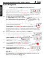
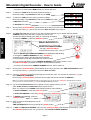
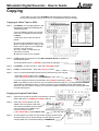
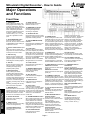
DIGITAL RECORDER
HOW TO USE GUIDE
MODELS
DX-TL2500E
DX-TL950E250
DX-TL800E120
THIS HOW TO GUIDE IS IMPORTANT TO YOU. PLEASE READ IT BEFORE USING YOUR DIGITAL RECORDER.
Note that this guide is based on the DX-TL2500E Digital Recorder.
Mitsubishi Digital Recorder - How to Guide
PLAYBACK
Basic Playback
Note: While you are in the PLAYBACK mode the DVR will continue to record.
Step 1.
To enter the PLAYBACK mode.
Open the front panel, and on the far right you will see four buttons:
STOP, PAUSE, REV.PLAY(-) and PLAY.
To playback a recorded time period - press the [ REV. PLAY(-) ] button.
Playback will begin from the earliest recorded memory, and will appear in reverse mode. Depending on
how the recorder is set up, some camera images may not appear at first.
Step 2.
You will now need to select the desired LAYOUT VIEW.
For a SINGLE CAMERA press an individual camera button (1.)
For MULTIPLE CAMERAS press the [ SPLIT/SEQUENCE ]
button until the desired camera view combination appears.
Step 3.
Once you have selected your desired layout view, you can now REWIND or FFWD from the recorded
time shown.
To rewind - turn the [ SHUTTLE RING ] anticlockwise (to the left) and hold.
Note the further the dial is turned, the faster the rewind speed.
An increase in speed is acknowledged by a short beep.
To FAST-FORWARD - turn the [ SHUTTLE RING ] clockwise (to the right) and hold.
Note the further the dial is turned, the faster the forward speed. An increase in speed is acknowledged by a short beep.
Depending on the way the recorder is set up, some images will appear on playback, but will not appear
when searching in FFWD or REW mode. To find a specific time and date, refer to the Advanced Search
instructions.
Step 4.
Once the [ SHUTTLE RING ] is released - the recorder will go into PAUSE mode.
Step 5.
Now that you have found the period of recorded time that you wish to view, you
can either PLAY Forward or Backwards from that point in time.
Note: You must be in the PAUSE mode first before either of the following.
To PLAY FORWARD - press the [ PLAY(+) ] button.
To PLAY BACKWARDS - press the [ PAUSE ] then the [ REV. PLAY(-) ] button.
Step 6.
To PAUSE your viewing - press the
[ PAUSE ] button.
Step 7.
If you need to MOVE FRAME BY FRAME - press the [ PAUSE ] button, then
To FRAME ADVANCE - turn the [ JOG DIAL ] clockwise (to the right).
To FRAME REWIND - turn the [ JOG DIAL ] anticlockwise (to the left).
Step 8.
Once you have finished playback you can return to the
LIVE RECORDING SCREEN by pressing the [ STOP ] button.
Step 9.
To RESUME PLAYBACK after the [ STOP ] button has been pressed - press the [ REV. PLAY(-) ] button
as per (Step 1.).
Note: Playback will resume from the last playback time period. If you need to Fast-forward or Rewind to a
new time then follow (Step 3.). To go to the start or end of any recorded time you will need to use the
SEARCH function, please refer to the “Searching” Guide.
Page 1
Mitsubishi Digital Recorder - How to Guide
Advanced Searching
Note: While you are in the SEARCH mode the DVR will continue to record.
The recorder will beep to let you know you’ve completed each task successfully.
Step 1.
To enter the SEARCH mode.
Open the front panel, and to the right of the middle you
will see a group of 9 buttons.
To search for a recorded time
period – press the [ SEARCH ] button.
If TIME DATE SEARCH appears on screen, move to Step 2.
Else depending on the last type of search method used, various search menus may appear.
Using the [ JOG DIAL ], select SEARCH TYPE, and then turn the [ SHUTTLE RING ] clockwise. The
SEARCH TYPE will flash.
Using the [ JOG DIAL ], select TIME DATE, and then turn the [ SHUTTLE RING
] clockwise. Now turn the [ SHUTTLE RING ] anticlockwise, to go back to the
TIME DATE SEARCH menu. Now move to Step 2.
Step 2.
The TIME DATE SEARCH menu will now appear on your display monitor.
You will notice [ >> ] next to the start of the Date and Time.
The [ >> ] arrows represent what line of the menu you are about to
edit. At the moment this will be the Date / Time that you wish to find.
Below this there is:
[ START ] - this is the start point of all recorded time.
[ END ] - this is the end point of all recorded time.
Note that you can only search between the START and
END Date / Times shown.
Step 3.
To SEARCH you now need to enter a Date / Time.
Do this by turning the [ SHUTTLE RING ] clockwise (to the right) once.
~ Now the DAY will be highlighted.
To edit the DAY turn the [ SHUTTLE RING ] clockwise (to the right) once again.
~ Now the DAY will be flashing.
To change the value of the DAY turn the [ JOG DIAL ] clockwise (to the right) to
increase the day or anticlockwise (to the left) to decrease the day.
Once you have selected the correct DAY that you wish to search, turn
the [ SHUTTLE RING ] clockwise once again, and the flashing will stop and the day
will be highlighted once again.
~ You have now selected the DAY that you want to search in.
Step 4.
Next you will need to select the MONTH. At present the DAY is highlighted.
To select the MONTH you need to turn the [ JOG DIAL ] clockwise (to the right) once.
~ Now the MONTH will now be highlighted.
To edit the MONTH turn the [ SHUTTLE RING ] clockwise (to the right) once again.
~ Now the MONTH will be flashing.
To change the value of the MONTH turn the [ JOG DIAL ] clockwise (to the right) to increase the month
or anticlockwise (to the left) to decrease the month.
Once you have selected the correct MONTH that you wish to search in, turn the [ SHUTTLE RING ]
clockwise once again, and the flashing will stop and will be highlighted once again.
Page 2
SEARCH
Press [ SEARCH ] a second time to enter the SEARCH SELECTION menu.
Mitsubishi Digital Recorder - How to Guide
~ You have now selected the MONTH that you want to search in.
Step 5.
To select the YEAR follow the same procedure of Step 4.
Note where Step 4 says MONTH this will now be YEAR.
Step 6.
To select the TIME follow the same procedure of Step 4.
Note where Step 4 says MONTH this will now be HOUR of the Day.
Or MINUTE of the Hour.
Or SECOND of the Minute.
Step 7.
Now turn the [ SHUTTLE RING ] anticlockwise (to the left) to go back to the TIME DATE SEARCH menu.
You will now notice [ >> ] next to the start of the Date and Time as per Step 2.
Step 8.
The Date and Time that you wish to view has now been selected. If you need to select a specific
CAMERA please follow this step, or else if you wish to view
all camera’s (default setting) go to Step 10 - Executing the Search.
To select a CAMERA - press the [ SEARCH ] button.
SEARCH
Now you will be viewing the
SEARCH SELECTION menu.
You will notice [ >> ] next to the
SELECTION CAMERA NUMBER
- turn the [ SHUTTLE RING ]
clockwise (to the right) once.
~ Now the SELECTION CAMERA NUMBER will be highlighted and flashing.
To change the CAMERA NUMBER turn the [ JOG DIAL ]
clockwise (to the right) to increase the camera number
or anticlockwise (to the left) to decrease the camera number.
Once you have selected the correct CAMERA NUMBER that you wish to search in, turn
the [ SHUTTLE RING ] clockwise once again, and the flashing will stop.
~ You have now selected the CAMERA NUMBER that you want to search in.
Step 9.
Now turn the [ SHUTTLE RING ] anticlockwise (to the left) to go back to the TIME DATE SEARCH menu.
You will now notice [ >> ] next to the start of the Date and Time.
Step 10. Turn the [ JOG DIAL ] clockwise (to the right) to move down a line. You should now have the [ >> ] next
to the EXECUTE (FORWARD).
Now turn the [ SHUTTLE RING ] clockwise (to the right) and this will execute the SEARCH.
Note: If you need to change the SEARCH Date and Time again, then you can turn the [ JOG DIAL ] anticlockwise (to the left) to
move up a line. You will now have the [ >> ] next to the Date and Time as per Step 2.
Step 10. The searched Date and Time will now appear on your display monitor, you can
either PLAY Forward or Backwards from this point in time.
Note: You most be in the PAUSE mode first before either of the following.
To PLAY FORWARD - press the [ PLAY(+) ] button.
To PLAY BACKWARDS - press the [ PAUSE ] then the [ REV. PLAY(-) ] button.
Step 11. To PAUSE your viewing - press the
[ PAUSE ] button.
Step 12. Once you have finished playback you can
return to the
TIME DATE SEARCH menu by pressing the [ STOP ] button.
Step 13. To EXIT the TIME DATE SEARCH menu turn the [ SHUTTLE RING ] anticlockwise (to the left) or - press
the [ SEARCH ] button twice, now you will be in the LIVE RECORDING SCREEN.
Page 3
Mitsubishi Digital Recorder - How to Guide
Copying
Note: While you are in the COPYING mode the DVR will continue to record.
The recorder will beep to let you know you’ve completed each task successfully.
Copying to Video Tape or DVD:
Step 1.
[ VCR/DVD ] For recording operations, see
the instruction manual accompanying the
VCR/DVD recorder
If your VCR/DVD recorder is connected
inline with your display monitor then go
to Step 2.
**Otherwise connect the recorder as
follows:
A. Connect RCA leads from the Front or
Rear AV output (OUTPUT A only) on the
DVR to the AV input on your VCR/DVD
recorder. The connectors
are colour coded, so make sure you
match them correctly.
Rear AV output (OUTPUT A only)
B. Select AV input on your recorder.
Step 2.
[ DVR ] Follow the instructions of the Basic Playback Guide to playback a
recorded time period.
Step 3.
[ VCR/DVD ] To start recording - press the [ RECORD ] button.
Step 4.
[ DVR ] To start playback - press the [ PLAY(+) ] button.
Step 5.
Once you have finished playing back the time period that you are copying.
- Press the [ STOP ] button on the [ DVR ].
- Press the [ STOP ] button on the [ VCR/DVD ].
If you are copying several time periods then use [ PAUSE ] instead of [ STOP ] .
Note: Your display monitor will show you the recording from the DVR only. To verify you have recorded
successfully to videotape or DVD, connect a monitor to your VCR/DVD recorder and playback the
sequence. On some DVD recorders, you will need to finalize the DVD Disk so that it can be played back
on other DVD players.
Copying to Compact Flash Card:
Step 1.
Open the front panel of the DVR, and insert the Compact
Flash Card into the [ COMPACT FLASH ] card slot.
Step 2.
Press the [ COPY ] button near the
middle of the front panel of the DVR.
The monitor will display a menu. Make
sure the DVR is set to HDD to CFC.
If not set correctly; use the
[ JOG / SHUTTLE ] to select HDD to CFC.
Step 3.
Choose whether you want to overwrite the existing contents of the
Compact Flash card or start recording from the last entry on the
compact flash card. The default setting is OVERWRITE.
Page 4
COPYING
The DVR should now be in [ PAUSE ] mode ready for playback.
Mitsubishi Digital Recorder - How to Guide
Step 4.
Select the desired TRANSFER PERIOD using the [ JOG / SHUTTLE ].
START-END - selects the recording start and end time/date. The recorder will copy all data from the HDD
between these times/dates.
START - selects the recording start time/date only. The recorder will copy all data from the HDD from this
start time/date.
LATEST DATA - refers to copying to an external device such as CD-Writer. Do not select
for copying to compact flash card.
Step 5.
Select the desired START or START/END time using the [ JOG / SHUTTLE ].
Step 6.
Select EXECUTE using the [ JOG / SHUTTLE ], then turn the [ SHUTTLE
RING ] clockwise to start copying.
If the copy operation does not start, turn the [ SHUTTLE RING ] anticlockwise
or press the [ COPY ] button on the DVR.
If a compact flash card is not inserted, COPY/NO MEDIA will be displayed
onscreen.
If the capacity of the compact flash card does not match the amount of data being copied,
COPY/SIZE/DATA ERROR will be displayed onscreen. In this case, restart using a narrower copy range,
or use a higher capacity card.
If data with no date is included in the copy range, COPY/SIZE/DATA ERROR will be displayed onscreen.
If you copy to compact flash card whilst still recording to HDD, some images may not be recorded to HDD
at the start and end times of the copy range.
Step 7.
[ Compact Flash Card continuous recording time (for 64MB) ]
COPYING
Displays the estimated recordable time (when recording on a 64MB Compact Flash Card).
• With Audio recording <Audio recording using 12.8KHz PCM sampling is possible.
: Since audio recording cannot be made during recording interval of 0.25P and 0.125P, even when
the recording with audio recording is set to ON, the recordable time is the same for when setting audio
recording to OFF.
: Recalculate the values on the recording times chart according to the capacity of the CFC you are
using. For example, for a 128MB CFC, multiply all the values by two.
: For usable Compact Flash Card, check with your dealer of purchase.
Page 5
Mitsubishi Digital Recorder - How to Guide
Copying to CD-WRITER:
Step 1.
Please make sure a CD-Writer is connected properly to the SCSI port on
the rear of the DVR.
If not, please contact your installer.
Step 2.
Press the [ COPY ] button on the front of the DVR.
A menu will appear on screen. Make sure the
DVR DIRECTION is set to HDD to COPY.
If not; use the [ SHUTTLE RING ] ring to set correctly.
Step 3.
Choose the MODE - whether you want to overwrite or start recording
from the last entry on the CD media. The default setting is OVERWRITE.
OVERWRITE: Overwrites current data on CD Media.
NO OVERWRITE: Writes following last entry on CD Media.
Step 4.
Select the desired TRANSFER PERIOD using the [ JOG / SHUTTLE ]
START-END - selects the recording start and end time/date. The recorder
will copy all data from the HDD between these times/dates.
START - selects the recording start time/date only. The recorder will copy
all data from the HDD from this start time/date
Step 5.
Select the desired START or START/END time using the
[ JOG / SHUTTLE ].
Step 6.
Select EXECUTE using the [ JOG DIAL ] then turn
the [ SHUTTLE RING ] clockwise to start copying.
If the copy operation does not start, turn the [ SHUTTLE RING ]
anticlockwise or press the COPY button on the DVR.
Page 6
COPYING
LATEST DATA - starts copying from the end of the last recording on the
CD-ROM, if sufficient memory is available.
Mitsubishi Digital Recorder - How to Guide
Major Operations
and Functions
Front View
FUNCTIONS
1. ZOOM button
When pressing this button once
during single screen display, the
screen is magnified by 100%. In
the same way, pressing the button
twice magnifies the screen by
200% and pressing the button
three times magnifies the screen
by 400%. Pressing a camera
number button (1, 2, 3, or 4) will
move the magnification center
point.
11. M-DET indicator
Illuminates when the motion
detection function is on.
12. EMERGENCY indicator
Flashes during emergency
recording and lights when
recording is completed.
13. ACCESS indicator
Illuminates during access to hard
disk drive, Compact Flash Card or 23. POWER button
peripheral recording devices.
When pressing this button while
2. SPLIT/SEQUENCE button
the MAIN switch on the rear of this
Press the button to display
14. COM (COMMUNICATION)
unit is set to ON, the power turns
SPLIT16, SPLIT9, SPLIT4 screen indicator
on and the button lights. When the
or SEQUENCE screen setting on Illuminates when establishing the button is pressed again, the unit
multiplexer functions.
communication with personal
will be in stand-by and the light will
computer.
turn off. When the unit is in
3. Camera number buttons (1 to
operational transition such as
16)
15. LOCK button
booting, the button will flash and
Press the button to display the
Pressing it with a pointed object
other operations are not accepted.
image from the camera connected (such as a ballpoint pen) while the
to this input on to the monitor.
MAIN switch (main power) on the 24. TIMER button
rear of the unit is on, will activate
When pressing this button, the unit
4. SHUTTLE ring
the simple lock or password lock. is set to timer recording/stand-by
Used to set various menus and
Moreover, the PASSWORD can be and the TIMER indicator lights.
search functions, adjusting the
set on the <PASSWORD
When pressing this button for more
playback speed, and rewinding or SETTING> screen. The indicator
than 1 second, timer
forwarding the recording images.
will light while the lock is active.
recording/stand-by is cancelled
and the TIMER indicator turns off.
5. JOG dial
16. LOCK indicator
Used to set various menus and
Illuminates when simple lock or
25. ANALOGUE OUT connectors
search functions, forwarding or
password lock is on.
VIDEO OUT connector
rewinding the image during
Output connector for video signal
playback (field-by-field).
17. WARNING RESET button
(RCA pin).
This button is used to clear onAUDIO OUT connector
6. REC/STOP button
screen warning display
Output connector for audio signal
When pressing this button,
and clear data.
(RCA pin).
recording starts and the button
lights. When pressing the button
18. SET UP button
26. COMPACT FLASH slot
for more than 1 second, the
Press this button to display the
Compact Flash Card can be used
recording stops and the light turns <SETTINGS> menu.
for saving/loading data and menus.
off. When pressing this button for
When not using the slot, attach the
more than 1 second during alarm 19. SEARCH button
COMPACT FLASH slot cover to
recording, recording stops. During Press this button to display the
prevent dust from entering within
timer
<SEARCH > menu.
the unit. * Compact FlashTM is a
recording, recording will not stop
trademark of SanDisk Corporation.
even if the button is pressed.
20. COPY button
Press this button to display
27. CFC (Compact Flash Card)
7. ARCHIVE button
<COPY> menu. This button lights
indicator
Press the button to archive. When when performing copy operation.
Illuminates only when the CFC is
pressing the button for more than 1 Copies cannot be made when the
selected by pressing the PLAY
second, archive stops. The unit will copy device is not connected or a
DEVICE button.
not start to archive if an archive
card is not in the COMPACT
device is not connected to the unit. FLASH slot.
28. MULTIPLEXER buttons
OUTPUT A button
8. OUTPUT B indicator
21. ALARM INTERRUPT button
When this button is pressed
Illuminates when pressing the
When pressing this button, the unit
operation of the camera number
OUTPUT B button.
will not accept alarm signals or
buttons and the
motion detection for 5 minutes.
SPLIT/SEQUENCE button
9. TIMER indicator
During this time, the button will
switches image output to the
Illuminates during timer recording flash. This allows device set-up
OUTPUT A connector and
or timer recording stand-by.
changes to be made without being
ANALOGUE OUT connectors.
disturbed by ALARMS. Press this
OUTPUT B button
10. PRE ALARM indicator
button once again to cancel.
When this button is pressed
Illuminates during pre-alarm
operation of the camera number
recording mode.
22. PLAY DEVICE button
buttons and the
Press this button to select
SPLIT/SEQUENCE button
PLAYBACK device.
Page 7
switches image output to the
OUTPUT B connector. Please note
that with this function, playback
display of an already recorded
image is not possible. A playback
image can not be output to the
OUTPUT B connector. To display
image of the monitor connected to
OUTPUT B, set to “ON” in the
setting of the “OUTPUT B
ON/OFF” of the <MPX DISPLAY
SETTINGS> screen.
29. EJECT button
Use this button to remove media
from externally connected devices.
30. PLAY DEVICE indicator
Lights the indicator corresponding
to the device selected with the
PLAY DEVICE button.
31. OPERATION buttons
STOP button
Press to stop playback.
PAUSE / SHUTTLE HOLD button
When pressing this button during
playback, the unit switches to still
frame playback and the button
lights. When pressing this button
again, the unit resumes playback
and the button turns off. When
pressing this button during shuttle
playback, the set playback speed
is maintained even when letting go
of the SHUTTLE ring.
REV. PLAY (REVERSE PLAY)
button
When pressing this button, the unit
switches to reverse playback and
the button lights.
PLAY button
When pressing this button, the unit
starts playback and the button
lights.
PLAY MODE buttons
The playback interval can be
changed during normal and
reverse playback by pressing
PLAY(+) or REV. PLAY( - ).
Mitsubishi Digital Recorder - How to Guide
Back View
1. MAIN switch
This is the main power switch.
When using this unit, set this
switch to ON. Otherwise, the power
cannot be turned on/off using the
POWER button on the front of the
unit.
2. CAMERA OUT connectors
Camera video output connectors
for use of BNC connectors. If the
MAIN switch is ON, the loop
through output is possible for the
camera image inputted into each
CAMERA IN connector.
3. CAMERA IN connectors
Input connector for signal of
camera (BNC connector).
4. GND terminals
It is the common GND terminal.
5. AUDIO connectors
AUDIO IN connector
Input connector for audio signal
(RCA pin).
AUDIO OUT connector
Output connector for audio signal
(RCA pin).
6. MIC jack
Input connector for microphone
(600 ohm impedance). Use of MIC
for audio recording has priority to
use of the AUDIO IN connector.
7. AC power socket
This socket connects to the power
cord. Earth terminal is for safety.
Use the 100 ~ 240V plug with earth
for the power of this unit.
! Please use the AC power cord
accessory.
8. VIDEO OUT connectors
OUTPUT A VIDEO connector
Output connector for video signal
to monitor (BNC connector).
OUTPUT A S(Y/C) connector
This is output connector for video
signals that separate brightness
signals and color signals for higher
picture quality. Simultaneous
output along with OUTPUT A
VIDEO is also possible.
OUTPUT B connector
Output connector for video signal
to monitor only for live image (BNC
connector).
9. RS-485/RS-422 connectors
Connectors for operations of pan,
tilt and zoom when these
connectors are connected to dome
camera.
10. REMOTE jack
Input connector for wired remote
control.
11. RESET button
Pressing this button resets the unit
and the power turns off. In this
! This unit must be earthed at all
case, video data, menu settings
times. Never connect this unit to a and the current time are kept.
power outlet which does not have
an earth terminal.
12. ALARM IN terminals
Input terminal for alarm signal.
13. I/O terminals
CLOCK ADJ terminal
Input terminal to set the present
time. Time display is adjusted to
the nearest hour (00 minutes 00
seconds) when this terminal
receives the CLOCK ADJ signal.
INFORMATION
The on-screen clock can be reset
to the nearest hour, by applying a
signal to the CLOCK ADJ terminal.
For example, if the current time is
11:29:59, it will be reset to
11:00:00, and if the current time is
11:30:00, it will be reset to
12:00:00.
REC terminal
Input terminal to start recording.
Not available during timer
recording.
EMERGENCY terminal
Input terminal initiating immediate
shift to EMERGENCY recording
mode compulsorily.
MODE OUT 1 ~ MODE OUT 5
terminals
Output terminal to indicate the
unit’s current mode. Select the
unit’s condition by MODE OUT 1 ~
MODE
OUT 5 setting in the <REAR
TERMINAL SETTINGS> menu.
CALL OUT terminal / CALL OUT
GND terminals
This is the ISOLATION output
terminal. Information that can be
transmitted externally consists of
CALL OUT settings made on the
<REAR TERMINAL SETTINGS>
menu screen as well as fixed
output settings.
DC 5V OUT terminal
Will only output when both the
MAIN switch and POWER button
are ON. The maximum electric
current is 30mA.
14. RS-232C connector
This connector is used to connect
to host device with RS-232C
connector. This unit can be
controlled by another device
through this connector.
15. ETHERNET connector
Use a 10BASE-T cable to connect
to the Ethernet terminal. Please
use the cable adapted to 10BASET. DUPLEX MODE is HALF
DUPLEX.
RECEIVE indicator
Illuminates when the unit is
receiving a signal.
SEND indicator
Illuminates when the unit is
transmitting a signal.
16. SCSI connector
This connector is used to connect
to peripheral recording device.
Inserting/Ejecting Compact Flash Card
Before using the Card, read the cautionary notes described in the manual included with Compact Flash Card.
2. Please turn down the side which contains notch in right and left,
securely insert the Card until the CFC EJECT button pops out.
a) Do not eject the Card when copying/restoring, copying/ loading
menus, or immediately after inserting the Card. The Card or the
contained data may become damaged.
b) Securely insert the Compact Flash Card. Otherwise, the unit may not
work properly.
c) Please use the Compact Flash Card which we recommend. When a
non recommended Card is used, there is a possibility that reading and
writing of data may not operate correctly.
d) For usable Compact Flash Card check with your dealer of purchase.
e) When using a new Card, be sure to execute CFC DATA CLEAR in the
<INFORMATION/SERVICE> screen.
<Ejecting Card>
1. Press the CFC EJECT button and eject the Card.
2. Attach the COMPACT FLASH slot cover.
Page 8
FUNCTIONS
<Inserting Card>
1. Remove the COMPACT FLASH slot cover attached to the unit.
Mitsubishi Digital Recorder - How to Guide
Options
Listed below are some of the devices that can be connected to your Mitsubishi Electric Digital Recorder…
Video
Printers
WAN / LAN
External
SCSI Disk
Drives
IDE Disk
Drives via
SCSI Bridge
VCR
SCSI
CD-Writers
[CFC]
Compact
Flash
DVD
Recorders
For more information on what devices you can use, and where to buy these devices please contact your Security
Specialist or BDT.
Black Diamond Technologies Limited
Head Office
Auckland
Christchurch
1 Parliament Street, Lower Hutt
PO Box 30-772
Phone: (04) 560 9100
Fax:
(04) 560 9130
Unit 1, 4 Walls Road,
Penrose
Phone: (09) 526 9340
Fax:
(09) 526 9369
Suite 2, Level 1,
37 Mandeville Street
Phone: (03) 341 7052
Fax:
(03) 341 7054
Web: www.bdt.co.nz
© 2004 BDT Limited
Version 1.0
26-04-2004
Page 9