1
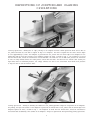
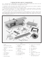
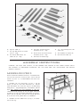
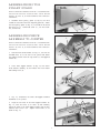
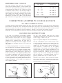
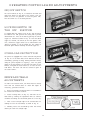
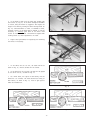
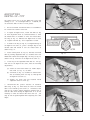
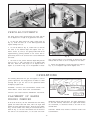
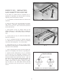
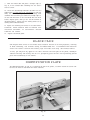
(Model 37-285)
Record this information for future
reference.
SERIAL NO._____________________
D ATE O F P U R C H A S E ____________
See Table of Contents for location of
Serial No.
D ATED 1-20-99
PA RT NO. 1347169
'Delta International Machinery Corp. 1999
INSTRUCTION M A N U A L
6 Motorized Jointer
TA B L E O F C O N T E N T S
SAFETY RULES ...............................................................................................................................................................3
ADDITIONAL SAFETY RULES F O R JOINTERS.............................................................................................................4
DEFINITIONS O F JOINTING & PLANING O P E R ATIONS...............................................................................................5
U N PACKING A N D CLEANING.........................................................................................................................................6
A S S E M B LY INSTRUCTIONS ...........................................................................................................................................7
Assembling Stand...................................................................................................................................................7
Assembling Stand And Dust Chute To Jointer ....................................................................................................8
Assembling Belt And Pulley Guard.......................................................................................................................8
Assembling Motor Pulley Guard ...........................................................................................................................9
Assembling Fence Assembly To Jointer ..............................................................................................................9
Assembling Cutterhead Guard ............................................................................................................................10
EXTENSION C O R D S ......................................................................................................................................................11
CONNECTING JOINTER TO P O W E R S O U R C E ...........................................................................................................11
Power Connections...............................................................................................................................................11
Grounding Instructions ........................................................................................................................................11
O P E R ATING C O N T R O L S A N D ADJUSTMENTS
On/Off Switch ........................................................................................................................................................12
Locking Switch In The OFF Position...............................................................................................................12
Overload Protection..............................................................................................................................................12
Knife And Table Adjustments ..............................................................................................................................12
Adjusting Depth-Of-Cut ........................................................................................................................................14
Fence Adjustments ...............................................................................................................................................14
O P E R ATIONS
Placement of Hands During Feeding ..................................................................................................................15
Jointing An Edge...................................................................................................................................................16
Planing Or Surfacing ............................................................................................................................................16
Beveling .................................................................................................................................................................17
Taper Cuts..............................................................................................................................................................17
Cutting A Rabbet...................................................................................................................................................17
Planing Warped Pieces.........................................................................................................................................18
Planing Short Or Thin Work.................................................................................................................................18
Direction Of Grain .................................................................................................................................................18
MAINTENANCE A N D R E PAIRS
Whetting Knives ....................................................................................................................................................18
Removing, Replacing, And Resetting Knives ....................................................................................................19
Blade Care .............................................................................................................................................................20
IDENTIFICATION PLATE................................................................................................................................................20
CONSTRUCTING A P U S H STICK .................................................................................................................................21
W A R R A N T Y ....................................................................................................................................................................22
2
SAFETY RULES
W oodworking can be dangerous if safe and proper operating procedures are not followed. As with all machinery, there are certain
hazards involved with the operation of the product. Using the machine with respect and caution will considerably lessen the possibility of personal injury. However, if normal safety precautions are overlooked or ignored, personal injury to the operator may result.
Safety equipment such as guards, push sticks, hold-downs, featherboards, goggles, dust masks and hearing protection can reduce
your potential for injury.But even the best guard won t make up for poor judgment, carelessness or inattention. Always use common
sense and exercise caution in the workshop. If a procedure feels dangerous, don t try it. Figure out an alternative procedure that feels
safer. REMEMBER: Your personal safety is your responsibility.
This machine was designed for certain applications only. Delta Machinery strongly recommends that this machine not be modified
and/or used for any application other than that for which it was designed. If you have any questions relative to a particular application, DO N O T use the machine until you have first contacted Delta to determine if it can or should be performed on the product.
D E LTA INTERNATIONAL MACHINERY C O R P.
M A N A G E R O F TECHNICAL S E RVICES
246 A L P H A DRIVE
PITTSBURGH, PENNSYLVANIA 15238
(IN CANADA: 644 IMPERIAL ROAD, GUELPH, ONTARIO
N1H 6M7)
W ARNING: FAILURE TO F O L L O W THESE RULES
M AY RESULT IN SERIOUS P E R S O N A L INJURY
15. MAINTAIN TO O L S IN TO P CONDITION. Keep tools
sharp and clean for best and safest performance. Follow
instructions for lubricating and changing accessories.
1. F O R Y O U R O W N S A F E T Y, READ INSTRUCTION
M A N U A L B E F O R E O P E R ATING T H E TO O L. Learn the
tool s application and limitations as well as the specific
hazards peculiar to it.
16. DISCONNECT TO O L S before servicing and when
changing accessories such as blades, bits, cutters, etc.
2. K E E P G U A R D S IN PLACE and in working order.
17. U S E R E C O M M E N D E D ACCESSORIES. The use of
accessories and attachments not recommended by Delta
may cause hazards or risk of injury to persons.
3. A LW AY S W E A R E Y E PROTECTION.
4. R E M O V E ADJUSTING KEYS A N D W R E N C H E S. Form
habit of checking to see that keys and adjusting wrenches are
removed from tool before turning it on.
18. R E D U C E T H E RISK O F UNINTENTIONAL S TA R TING. Make sure switch is in OFF position before plugging
in power cord.
5. K E E P W O R K A R E A C L E A N. Cluttered areas and
benches invite accidents.
19. N E V E R STA N D O N TO O L. Serious injury could occur
if the tool is tipped or if the cutting tool is accidentally
contacted.
6. DON T U S E IN D A N G E R O U S ENVIRONMENT. Don t
use power tools in damp or wet locations, or expose them
to rain. Keep work area well-lighted.
9. DON T FORCE TO O L. It will do the job better and be
safer at the rate for which it was designed.
20. C H E C K D A M A G E D PA R T S. Before further use of the
tool, a guard or other part that is damaged should be carefully checked to ensure that it will operate properly and
perform its intended function check for alignment of moving
parts, binding of moving parts, breakage of parts, mounting,
and any other conditions that may affect its operation. A
guard or other part that is damaged should be properly
repaired or replaced.
10. U S E RIGHT TO O L. Don t force tool or attachment to do
a job for which it was not designed.
21. DIRECTION O F FEED.Feed work into a blade or cutter
against the direction of rotation of the blade or cutter only.
11. W E A R P R O P E R A P PA R E L. No loose clothing, gloves,
neckties, rings, bracelets, or other jewelry to get caught in
moving parts. Nonslip footwear is recommended. Wear
protective hair covering to contain long hair.
22. N E V E R L E AV E TO O L RUNNING UNATTENDED. TURN
P O W E R O F F. Don t leave tool until it comes to a complete
stop.
7. K E E P CHILDREN A N D VISITO R S AW AY. All children
and visitors should be kept a safe distance from work area.
8. M A K E W O R K S H O P CHILDPROOF
with padlocks,
master switches, or by removing starter keys.
23. DRUGS, ALCOHOL, MEDICATION. Do not operate
tool while under the influence of drugs, alcohol or any
medication.
12. A LW AY S U S E SAFETY GLASSES.W ear safety glasses.
Everyday eyeglasses only have impact resistant lenses;
they are not safety glasses. Also use face or dust mask if
cutting operation is dusty.
24. M A K E S U R E TO O L IS DISCONNECTED FROM POWER
SUPPLY while motor is being mounted, connected or reconnected.
13. S E C U R E W O R K. Use clamps or a vise to hold work
when practical. It s safer than using your hand and frees
both hands to operate tool.
25. W ARNING: The dust generated by certain woods and
wood products can be injurious to your health. Always operate machinery in well ventilated areas and provide for proper
dust removal. Use wood dust collection systems whenever
possible.
14. DON T O V E R R E A C H. Keep proper footing and balance
at all times.
3
ADDITIONAL SAFETY RULES FOR
JOINTERS
1. W ARNING: Do not operate the jointer until it is
completely assembled and installed according to the
instructions.
15. N E V E R make jointing or planing cuts deeper than
1/8 inch. On cuts more than 1-1/2 inches wide, adjust
depth of cut to 1/16 inch or less to avoid overloading
machine and to minimize chance of kick-back (work
thrown back toward you).
2. IF YOU ARE NOT thoroughly familiar with the operation of jointers, obtain advice from your supervisor,
instructor or other qualified person.
16. MAINTAIN the proper relationship of infeed and outfeed table surfaces and cutterhead knife path.
3. K E E P cutterhead sharp and free of all rust and pitch.
17. S U P P O R T the workpiece adequately at all times
during operation; maintain control of the work at all times.
4. B E F O R E starting machine, check cutterhead guard
to make sure it is not damaged and operates freely.
18. DO NOT back the workpiece toward the infeed table.
5. A LW AY S make sure exposed cutterhead behind the
fence is guarded, especially when jointing near the edge.
19. DO NOT attempt to perform an abnormal or littleused operation without study and the use of adequate
hold-down/push blocks, jigs, fixtures, stops, push blocks,
etc.
6. N E V E R perform jointing or planing operations with
the cutterhead guard removed.
20. SHUT OFF power before servicing or adjusting jointer.
7. MAKE CERTAIN the infeed and outfeed tables are
tightened before starting the machine.
21. DISCONNECT jointer from power source and clean
the machine before leaving it.
8. N E V E R start the jointer with the workpiece contacting the cutterhead.
22. MAKE SURE the work area is clean before leaving
the machine.
9. A LW AY S hold the workpiece firmly against the
tables and fence.
23. S H O U L D any part of your jointer be missing, damaged, or fail in any way, or any electrical component fail
to perform properly, shut off switch and remove plug from
power supply outlet. Replace missing, damaged or failed
parts before resuming operation.
10. N E V E R perform any operation Free-hand which
means using your hands to support or guide the workpiece. A LW AYS use the fence to position and guide the
work.
24. THE USE of attachments and accessories not recommended by Delta may result in the risk of injuiries.
11. AVOID awkward operations and hand positions
where a sudden slip could cause your hand to move into
the cutterhead.
25. ADDITIONAL INFORMATION regarding the safe
and proper operation of this product is available from the
National Safety Council, 1121 Spring Lake Drive, Itasca,
IL 60143-3201 in the Accident Prevention Manual for
Industrial Operation and also in the Safety Data Sheets
provided by the NSC. Please also refer to the American
National Standatd Institute ANSI 01.1 Safety
Requirements for Woodworking Machinery and the U.S.
Department of Labor OSHA 1910.213 Regulations.
12. A LW AY S use hold-down/push blocks for jointing
material less than 3 inches in height or planing material
thinner than 3 inches.
13. DO NOT perform jointing operations on material
shorter than 10 inches, narrower than 3/4 inch or less
than 1/2 inch thick.
14. DO NOT perform planing operations on material
shorter than 10 inches, narrower than 3/4 inch, wider
than 6 inches or less than 1/2 inch thick.
26. S AVE THESE INSTRUCTIONS. Refer to them often
and use them to instruct others.
4
DEFINITIONS O F JOINTING AND PLANING
O P E R ATIONS
Fig. 2
Jointing Operations - Jointing cuts or edge jointing is the simplest and most common operation which can be done on
the jointer and these cuts are made to square an edge of a workpiece. The fence is square with the table and the depth
of cut is approximately 1/8 inch. The workpiece is positioned on the jointer with the narrow edge of the workpiece on the
infeed table and the major flat surface of the workpiece against the fence, as shown in Fig. 2. The workpiece is moved
from the infeed table, across the cutterhead to the outfeed table. The hand over the outfeed table presses the work down
so that the newly-formed surface will make perfect contact with the table. The hand over the infeed table (usually the
right hand) exerts no downward pressure, but simply advances the work to the cutterhead. Both hands exert pressure
to keep the work in contact with the fence.
Fig. 3
Planing Operations - Planing or surfacing are identical to the jointing operation except for the position of the workpiece.
For planing, the major flat surface of the workpiece is placed on the infeed table of the jointer with the narrow edge of the
workpiece against the fence, as shown in Fig. 3. The workpiece is moved from the infeed table, across the cutterhead to
the outfeed table establishing a flat surface on the workpiece. Always use push blocks when performing planing operations.
5
U N PACKING A N D CLEANING
The 6 Motorized Jointer is shipped complete in one container. Carefully unpack the jointer,stand, and all loose items
from the container. Figs. 4 and 5 illustrate the items supplied with the jointer.
1. W ARNING: For your own safety, DO NOT connect the jointer to a power source until the machine is completely
assembled and you have read and understood the entire owner s manual.
2. IMPORTA N T:When removing the jointer from the shipping container,D O N O T place the jointer on a flat surface.
Support the jointer at both ends with 4 x 4 lumber or similar material, as shown in Fig. 4. This will prevent any damage to the motor assembly, which is located on the base of the jointer.
3. CAUTION: Carefully remove the protective coating from the machined surfaces of the jointer. D O N O T let your
hands or fingers come in contact with the cutterhead knives as they are extremely sharp. D O N O T use acetone, gasoline or lacquer thinner to clean the jointer; use a soft cloth moistened with kerosene. After cleaning, cover the table surface with a good quality paste wax.
1
2
3
4
11
14
20
18
8
5
12
6
7
13
16
19
10
15
9
17
23
24
21
22
25
Fig. 4
1. Jointer
2. Belt and Pulley Guard
3. 1/4-20 x 1/2
Screw (2)
Truss Head
4. Guard
5. #8-32 x 1/4
Screw
Round Head
10. Fence Mounting Bracket
Assembly
18. 5/16-18 x 1-1/4
Screws (3)
11. Locking Lever
19. Flat Washers (6)
12. Flat Washer
20. 5/16
13. 1/4-20 x 3/4
Screws (2)
Flat Head
Hex Head
Hex Nuts (3)
21. Push Blocks (2)
22. Fence
14. Flat Washers (2)
23. Flat Washers (2)
6. Flat Washers (2)
15. 1-1/4-20 Hex Nuts (2)
7. #8-32 Hex Nut
16. Fence Support Bracket
24. 1/4-20 x 3/4
Screws
8. Dust Chute
17. Cap Screws (2)
9. Cutterhead Guard
6
Square Head
25. W renches (4): 2.5, 5, 6mm
and 8/10mm Open-end
27
26
28
29
34
33
32
30
31
Fig. 5
26. Legs for Stand (4)
27. Two Top End Braces for Stand
(10-1/2 long)
28. Two Bottom End Braces for
Stand (15-1/2 long)
29. Top Front and Rear Braces
for Stand (25-1/2 long)
32. 1/2 Long Carriage Bolts for
Stand (32)
30. Bottom Front and Rear Braces
for Stand (30-1/2 long)
33. Flat Washers for Stand (32)
34. Hex Nuts for Stand (32)
31. Four Feet for Stand Legs
A S S E M B LY INSTRUCTIONS
W ARNING: FOR YOUR OWN SAFETY, DO NOT CONNECT THE JOINTER TO THE POWER SOURCE UNTIL
THE JOINTER IS COMPLETELY ASSEMBLED AND YOU HAVE READ AND UNDERSTOOD THE ENTIRE
OWNERS MANUAL.
ASSEMBLING STA N D
B
M A K E C E R TAIN T H E MACHINE IS DISCONNECTED
F R O M T H E P O W E R S O U R C E A N D T H AT KNIFE
G U A R D (A) FIG. 13, IS POSITIONED O V E R THE CUTT E R H E A D.
C
A
A
D
1. Assemble two top end braces (A) Fig. 6, two top
braces (B) and (C), two lower end braces (D), and two
lower side braces (E) to the four legs (F) as shown using
thirty-two 1/2 long carriage bolts, flat washers, and hex
nuts. Only tighten hex nuts fingertight at this time.
IMPORTA N T:The top lips of the two upper end braces
(A) must fit on top of two upper side braces (B) and (C).
NOTE: The one top brace (B) with the slotted edge will
be at the rear of the jointer when it is assembled.
F
D
G
E
2. Assemble the four rubber feet (G) Fig. 6, to the bottom of each leg.
Fig. 6
7
ASSEMBLING STA N D A N D
D U S T C H U T E TO JOINTER
M A K E C E R TAIN T H E MACHINE IS DISCONNECTED
F R O M T H E P O W E R S O U R C E A N D T H AT KNIFE
G U A R D (A) FIG. 13, IS POSITIONED O V E R THE C U TTERHEAD.
1. Carefully turn the jointer (A) Fig. 7, upside-down so
the table is resting on a supporting surface similar to the
two pieces of 4 x 4 lumber as shown. This will facilitate the assembly of the dust chute (B) Fig. 8, and stand
(C) to the jointer.
A
2. Align the three mounting holes (D) Fig. 8, in the stand
with three mounting holes in the base of the jointer as
shown in Fig. 8.
Fig. 7
A
4. Assemble the dust chute (B) and stand (C) Fig. 9, at
each hole (D) with a 5/16-18 x 1-1/4 long hex head
screw (E), two flat washers (F), and hex nut (G). NOTE:
Screws are to be installed upward from the base of the
jointer.
D
5. Carefully turn the jointer with stand and dust chute
attached so the jointer is resting on the stand. IMPORTA N T:W e strongly suggest that two people perform this
operation.
D
D
6. Apply downward pressure on the jointer so the legs
of the stand are adjusted to the floor surface and tighten
allstand mounting hardware.
D
C
B
3. Position dust chute (B) Fig. 9, as shown, over two of
the holes (D) that were aligned in STEP 2.
Fig. 8
C
B
D
A
G
F
D
E
Fig. 9
Fig. 10
ASSEMBLING BELT
AND PULLEY G U A R D
A
M A K E C E R TAIN T H E MACHINE IS DISCONNECTED
F R O M T H E P O W E R S O U R C E A N D T H AT KNIFE
G U A R D (A) FIG. 13, IS POSITIONED O V E R THE C U TT E R H E A D.
B
1. Loosely thread two 1-1/4-20 x 1/2 truss head
screws (A) Fig. 10, into the two tapped holes at the rear
of the jointer table.
2. Insert slots in guard (B) under heads of screws (A)
as shown in Fig. 11, and tighten screws to hold guard in
position.
Fig. 11
8
ASSEMBLING M O TO R
PULLEY G U A R D
B
M A K E C E R TAIN T H E MACHINE IS DISCONNECTED
F R O M T H E P O W E R S O U R C E A N D T H AT KNIFE
G U A R D (A) FIG. 13, IS POSITIONED O V E R THE C U TT E R H E A D.
C
1. Assemble motor pulley guard (C) Fig. 12, so it fits
around the outside of the belt and pulley guard (B). Fasten
the motor pulley guard (C) Fig. 12, to the side of the stand
with #8-32 x 1/4 round head screw (D), two flat washers, and hex nut.
D
Fig. 12
ASSEMBLING FENCE
A S S E M B LY TO JOINTER
E
M A K E C E R TAIN T H E MACHINE IS DISCONNECTED
F R O M T H E P O W E R S O U R C E A N D T H AT KNIFE
G U A R D (A) FIG. 13, IS POSITIONED O V E R THE C U TT E R H E A D.
1. Position fence slide bracket (B) Fig. 13, over the two
threaded holes (C) at the rear of the jointer and fasten
the support bracket with two cap screws (D) and supplied
wrench (E).
A
D
C
B
Fig. 13
2. Place fence support bracket (F) Fig. 14, over rod in
slide bracket assembly (B) and fasten with flat washer
and locking lever (G).
F
G
B
Fig. 14
3. Fig. 15, illustrates the slide and support brackets
assembled to the jointer.
J
H
K
4. Align the two holes in the fence support bracket (H)
Fig. 15, with two holes (J) in fence (K) and carefully
fasten the fence to the fence support bracket with two flat
washers and 1/4-20 x 3/4 square head screws (L) as
shown in Fig. 16.
L
G
Fig. 15
9
5. Assemble the free end of spring (M) Fig. 16, onto the
rear edge of bracket (F). NOTE: The tension on spring
(M) Fig. 16, automatically allows safety guard (N) to move
forward with the fence (K) and over the rear of the cutterhead for operator safety.
K
6. I M P O R TA N T: R E M O V E KNIFE G U A R D F R O M
CUTTERHEAD A S S E M B LY.
M
N
F
Fig. 16
ASSEMBLING
CUTTERHEAD G U A R D
B
A
M A K E C E R TAIN T H E MACHINE IS DISCONNECTED
F R O M T H E P O W E R S O U R C E A N D T H AT KNIFE
G U A R D IS POSITIONED O V E R THE CUTTERHEAD.
C
1. Remove set screw (A) Fig. 17, from the post of the
cutterhead guard (B) with supplied wrench (C).
Fig. 17
2. Insert the post of cutterhead guard (B) Fig. 18, down
through hole (D) in the infeed table. NOTE: A spring is
supplied inside knob assembly (E) Fig. 18, that returns
guard (B) over the cutterhead after the cut has been
made. Turn knob (E) Fig. 18, to provide tension on the
spring before inserting the post. Make certain the
spring inside knob (E) engages slot in cutterhead
post and that the guard (B) is positioned over pin (F).
If spring tension is too much or too little, adjust the
tension spring accordingly by removing the guard and
rotating knob (E).
B
F
D
E
Fig. 18
3. Thread set screw (A) Fig. 19, which was removed in
STEP 1, back into post to keep cutterhead guard (B) in
position during jointer operation.
B
4. Fig. 19, illustrates the cutterhead guard (B) assembled to the infeed table. NOTE: When installed correctly,
the guard should spring back over the cutterhead after
the cut.
A
Fig. 19
10
EXTENSION C O R D S
TO TA L LENGTH O F
C O R D IN FEET
Use proper extension cords. Make sure your extension
cord is in good condition and is a 3-wire extension cord
which has a 3-prong grounding type plug and a 3-pole
receptacle which will accept the tool s plug. When using
an extension cord, be sure to use one heavy enough to
carry the current of the jointer. An undersized cord will
cause a drop in line voltage, resulting in loss of power
and overheating. Fig. 20 shows the correct gage to use
depending on cord length. If in doubt, use the next heavier
gage. The smaller the gage number, the heavier the cord.
G A G E O F EXTENSION
C O R D TO U S E
0 - 25
26 - 50
51 - 100
101 - 150
16
16
14
12
AW
AW
AW
AW
G
G
G
G
Fig. 20
CONNECTING JOINTER TO P O W E R S O U R C E
P O W E R CONNECTIONS
A separate electrical circuit should be used for your tools. This circuit should not be less than #12 wire and should be
protected with a 20 Amp fuse. Have a certified electrician replace or repair a worn cord immediately.Before connecting
the motor to a power line, make sure the switch is in the OFF position and be sure that the electric current is of the
same characteristics as stamped on the motor nameplate. Running on low voltage will damage the motor.
W ARNING: D O N O T E X P O S E T H E TO O L TO RAIN O R O P E R ATE THE TO O L IN D A M P L O C ATIONS.
G R O U N D I N G INSTRUCTIONS
In the event of a malfunction or breakdown, grounding
provides a path of least resistance for electric current to
reduce the risk of electric shock. The motor is equipped
with an electric cord having an equipment-grounding
conductor and a grounding plug. The plug must be
plugged into a matching outlet that is properly installed
and grounded in accordance with all local codes and
ordinances.
Use only 3-wire extension cords that have 3-prong
grounding type plugs and 3-hole receptacles that accept
the tool s plug, as shown in Fig. 21.
Repair or replace damaged or worn cord immediately.
This tool is intended for use on a circuit that has an outlet and a plug that looks like the one shown in Fig. 21.
A temporary adapter, which looks like the adapter illustrated in Fig. 22, may be used to connect this plug to a
2-pole receptacle, as shown in Fig. 22, if a properly
grounded outlet is not available. The temporary adapter
should be used only until a propery grounded outlet can
installed by a qualified electrician. THIS A D A P T E R IS
N O T APPLICABLE IN CANADA. The green-colored
rigid ear, lug, and the like, extending from the adapter,
must be connected to a permanent ground, such as a
properly grounded outlet box, as shown in Fig. 22.
Do not modify the plug provided - if it will not fit the outlet,
have the proper outlet installed by a qualified electrician.
Improper connection of the equipment-grounding conductor can result in risk of electric shock. The conductor with
insulation having an outer surface that is green with or
without yellow stripes is the equipment-grounding conductor. If repair or replacement of the electric cord or plug is
necessary, do not connect the equipment grounding conductor to a live terminal.Check with a qualified electrician
or service personnel if the grounding instructions are not
completely understood, or if in doubt as to whether the
tool is properly grounded.
CAUTION: IN ALL CASES, MAKE CERTAIN THE RECEPTA C L E IN Q U E S T I O N IS P R O P E R LY G R O U N D E D .
IF Y O U ARE NOT SURE, HAV E A CERTIFIED ELECTRICIAN C H E C K THE RECEPTACLE.
GROUNDED OUTLET B O X
GROUNDED OUTLET B O X
CURRENT
C A R RYING
PRONGS
GROUNDING M E A N S
ADAPTER
GROUNDING BLADE IS
LONGEST O F THE THREE BLADES
Fig. 21
Fig. 22
11
O P E R ATING C O N T R O L S A N D ADJUSTMENTS
ON/OFF SWITCH
The on/off switch (A) Fig. 23, is located at the front left
side of the jointer.To give power to the jointer, move the
switch (A) to the UP position. To turn the power OFF,
move the switch (A) to the down position.
A
LOCKING SWITCH IN
T HE OFF POSITION
W e suggest when the jointer is not in use, that the switch
be locked in the OFF position for safety and to prevent
unwarranted use. This can be done by pulling the switch
toggle (B) outward as shown in Fig. 24. With the switch
toggle (B) removed, the switch (A) will not operate. However, should the toggle switch (B) be removed while the
jointer is running, it can be turned off, but cannot be
restarted again without inserting the switch toggle (B).
Fig. 23
A
B
O V E R L O A D PROTECTION
The jointer is equipped with a reset overload relay button
(C) Fig. 24. If the motor shuts off or fails to start due to
overloading (jointing too deep; working with dull knives;
using the jointer beyond its capacity), move the power
switch to the off position. Let the motor cool three to five
minutes, then push the reset button (C) to reset the overload device. The motor can then be turned on again in
the usual manner.
C
Fig. 24
B
A
KNIFE A N D TABLE
ADJUSTMENTS
In order to do accurate work, the knives must be exactly
level with the outfeed table. To check and adjust if
necessary, proceed as follows:
1. M A K E C E R TAIN THE MACHINE IS DISCONNECTE D F R O M THE P O W E R SOURCE.
Fig. 25
2. Loosen locking knob (B) Fig. 25, and lower the infeed table by turning the adjustment knob (A) counterclockwise and swing the cutterhead guard out of the way.
3. Place a steel straight edge on the outfeed table extending out over the cutterhead, as shown in Fig. 26.
4. Carefully rotate the cutterhead by hand. The knives
should just touch the straight edge.
Fig. 26
12
C
D
5. If the knife is high or low at either end, slightly turn
four screws (C) Fig. 27, in the knife locking bar clockwise
to loosen, using the wrench (D) supplied. Then adjust the
height of the knife by turning the knife raising screws (E)
Fig. 28, counterclockwise to lower, or clockwise to raise,
the knife. NOTE: If the knife must be lowered, it will be
necessary to carefully push down on the knife after
screws (E) have been turned. IMPORTA N T:Tighten knife
locking screws (C) after adjustments are made.
C
Fig. 27
6. Repeat these procedures for adjusting the remaining
two knives if necessary.
E
E
C
C
Fig. 28
7. If the knives are set too low, the result will be as
shown in Fig. 29, and the surface will be curved.
8. If the knives are set too high, the work will be gouged
at the end of the cut, as shown in Fig. 30.
9. As a final check, run a piece of work slowly over the
knives for 6 to 8 inches. The wood should rest firmly on
both tables, as shown in Fig. 31, with no open spaces
under the finished cut.
Fig. 29
Fig. 30
Fig. 31
13
B
ADJUSTING
DEPTH-OF-CUT
C
The jointer can be set to cut any depth from a very thin
shaving to 3/8 . If a cut deeper than 3/8 is desired, the
cut should be made in three or more passes.
D
A
1. M A K E C E R TAIN THE MACHINE IS DISCONNECTE D F R O M THE P O W E R S O U R C E.
Fig. 32
2. To adjust the depth-of-cut, loosen lock knob (B) Fig.
32. Turn adjustment knob (A) counterclockwise to lower
the infeed table or clockwise to raise the infeed table.
The ring (C) Fig. 32, indicates the depth-of-cut on scale
(D). Tighten lock knob (B), after adjustment is made.
3. To check if the ring (C) Fig. 32, is aligned correctly to
the depth-of-cut scale (D), place a straight edge on the
outfeed table and extend it over the infeed table as
shown in Fig. 33.
4. Loosen locking knob (B) Fig. 34, and raise the infeed
table by turning adjustment knob (A) clockwise until the
infeed table touches the straight edge. The ring (C) Fig. 34,
should line up with zero on the depth-of-cut scale (D).
Fig. 33
5. If the ring on the adjustment knob does not line up
with zero on the depth-of-cut scale, make the following
adjustments:
B
C
[a] Loosen set screw with wrench (E) inside adjustment knob (A) Fig. 34, as shown.
D
[b] Turn knob (A) Fig. 34, clockwise or counterclockwise as necessary until the ring (C) lines up with
the depth-of-cut scale (D).
E
[c] Tighten set screw that was loosened inside
adjustment knob in STEP [a].
A
Fig. 34
6. IMPORTA N T:The jointer features an automatic
table stop (F) Fig. 35, which does not allow the infeed
table to be lowered by more than 1/8 increments. This
also acts as a safety feature should the operator fail to
lock the table after setting the depth-of-cut. If it is ever
necessary to lower the infeed table more than 1/8 , the
stop (F) must be pushed upward while adjusting the table
height.
F
Fig. 35
14
B
C
B
D
D
A
G
E
Fig. 36
Fig. 37
FENCE ADJUSTMENTS
The fence can be easily moved across the table and can
tilt 45 degrees left or right at any position on the table.
D
1. To move the fence across the table, loosen lever (A)
Fig. 36, slide the fence (B) to the desired position and
tighten locking lever (A).
F
2. To tilt the fence (B) Fig. 36, loosen lever (C) and tilt
the fence to the desired angle and tighten lever (C).
NOTE: Levers (A) and (C) are spring-loaded and can be
repositioned by pulling outward on the levers and repositioning them on the serrated nut located underneath
the levers.
E
Fig. 38
sary, turn set screw (D) in or out until it contacts the stop
link (E) when the fence is set at 90 degrees to the table.
3. The fence on the jointer features adjustable positive
stops (D) Fig. 37, and a stop link (E) at 90 degrees right
and left. Check the fence angle at 90 degrees with a
square (F) as shown in Fig. 38. If an adjustment is neces-
4. Repeat this procedure to check the positive stops (D)
Fig. 37, at 45 degrees right and 45 degrees left
.
O P E R ATIONS
The following directions will give the beginner a start on
jointer operations. Use scrap pieces of lumber to check
settings and to get the feel of the operations before
attempting regular work.
W ARNING: A LW AYS USE CUTTERHEAD GUARD A N D
K E E P HANDS AW AY FROM THE CUTTERHEAD.
A LW AYS USE PUSH BLOCKS WHENEVER POSSIBLE.
PLACEMENT OF HANDS
DURING FEEDING
Fig. 39
taining flat contact with the fence. The right hand presses the work forward, and before the right hand reaches
the cutterhead, it should be moved to the work on the
outfeed table.
At the start of the cut, the left hand holds the work firmly
against the infeed table and fence, while the right hand
pushes the work toward the knives. After the cut is underway, the new surface rests firmly on the outfeed table as
shown in Fig. 39. The left hand should then be moved to
the work on the outfeed table, at the same time main-
CAUTION: NEVER PASS HANDS DIRECTLY OVER THE
CUTTERHEAD.
15
JOINTING AN EDGE
This is the most common operation for the jointer. Set the
guide fence square with the table. Depth of cut should be
the minimum required to obtain a straight edge. Hold the
best face of the piece firmly against the fence throughout
the feed as shown in Fig. 40.
Fig. 40
DO NOT PERFORM JOINTING OPERATIONS ON
M ATERIAL SHORTER THAN 10 INCHES, NARROWER THAN 3/4 INCH, OR LESS THAN 1/2 INCH THICK
(REFER TO FIG. 41).
Fig. 41
PLANING OR SURFACING
Planing or surfacing is identical to the jointing operation
except for the position of the workpiece. For planing, the
major flat surface of the workpiece is placed on the
infeed table of the jointer with the narrow edge of the
workpiece against the fence, as shown in Fig. 42. The
workpiece is moved from the infeed table, across the cutterhead to the outfeed table establishing a flat surface on
the workpiece Always use push blocks when performing
planing operations and never pass your hands directly
over the cutterhead.
Fig. 42
16
BEVELING
To cut a bevel, lock the fence at the required angle and
run the work across the knives while keeping the work
firmly against the fence and tables. Several passes may
be necessary to arrive at the desired result. When the
angle is small, there is little difference whether the fence
is tilted to the right or left. However, at greater angles
approaching 45 degrees, it is increasingly difficult to hold
the work properly when the fence is tilted to the right. The
advantage of the double-tilting fence is appreciated
under such conditions.
When tilted to the left, the fence forms a V-shape with the
tables, and the work is easily pressed into the pocket
while passing it across the knives. If the bevel is laid out
on the piece in such direction that this involves cutting
against the grain, it will be better to tilt the fence to the
right.
Fig. 43, illustrates a slight bevel being cut onto the edge
of a workpiece.
Fig. 43
TAPER CUTS
One of the most useful jointer operations is cutting an edge to a taper.The method can be used on a wide variety of
work. Tapered legs of furniture are a common example.
Instead of laying the piece on the infeed table, lower the forward end of the work onto the outfeed table. Do this very
carefully, as the piece will span the knives, and they will take a bite from the work with a tendency to kick back unless
the piece is firmly held. Now push the work forward as in ordinary jointing. The effect is to plane off all the stock in front
of the knives, to increasing depth, leaving a tapered surface.
The ridge left by the knives when starting the taper may be removed by taking a very light cut according to the regular
method for jointing, with the infeed table raised to its usual position.
Practice is required in this operation, and the beginner is advised to make trial cuts on waste material. Taper cuts over
part of the length and a number of other special operations can easily be done by the experienced craftsman.
CUTTING A R A B B E T
IMPORTA N T:D O N O T R E M O V E T H E C U T T E R H E A D
G U A R D W H E N P E R F O R M I N G RABBETING O P E R ATIONS.
Rabbeting is similar to a jointing operation except that
only a partial cut is made in the edge of the work surface,
as shown in Fig. 44.
Make certain the machine is disconnected from the
power source when adjusting the fence for rabbeting!
Adjust the fence to the desired width of the rabbet cut.
W ARNING:T H E U N C U T PORTION O F T H E R A B B E T
C A N N O T B E G R E ATER THAN 3/4 .
Hold the work firmly against the fence while making the
rabbet cut. NOTE: D O N O T M A K E C U T S G R E AT E R
T H A N 1/8 IN E A C H PASS. IF A D E E P E R C U T IS REQUIRED, MAKE SEVERAL C U T S TO A M A X I M U M O F
3/8 F O R THIS JOINTER.
Fig. 44
17
PLANING WARPED PIECES
If the wood to be planed is dished or warped, take light
cuts until the surface is flat. Avoid forcing such material
down against the table; excessive pressure will spring it
while passing the knives, and it will spring back and
remain curved after the cut is completed.
PLANING SHORT
OR THIN WORK
When planing short or thin pieces, always use push
blocks to minimize all danger to the hands. Fig. 45, illustrates using the Delta 37-108 Push Blocks properly.
Fig. 45
DO NOT PERFORM PLANING OPERATIONS ON
M ATERIAL SHORTER THAN 10 INCHES, NARROWER
THAN 3/4 INCH, WIDER THAN 6 INCHES, OR LESS
THAN 1/2 INCH THICK (REFER TO FIG. 46).
DIRECTION OF GRAIN
Avoid feeding work into the jointer against the grain as
shown in Fig. 47. The result will be chipped and splintered edges. Feed with the grain as shown in Fig. 48, to
obtain a smooth surface.
Fig. 46
Fig. 47
Fig. 48
MAINTENANCE A N D R E PAIRS
After considerable use, the knives will become dull and it will not be possible to do accurate work. Unless
badly damaged by running into metal or other hard material, the knives may be sharpened as follows:
WHETTING KNIVES
DISCONNECT THE MACHINE FROM THE POWER
S O U R C E. Use a fine carborundum stone, cover it partly
with paper as indicated in Fig. 49 to avoid marking the
table. Lay the stone on the infeed table, lower the table
and turn the cutterhead forward until the stone lies flat on
the bevel of the knife as shown. Hold the cutterhead from
turning, and whet the bevelled edge of the knife, stroking
lengthwise by sliding the stone back and forth across the
table. Do the same amount of whetting on each of the
three knives.
Fig. 49
18
REMOVING, REPLACING,
A N D RESETTING KNIVES
B
A
If the knives are removed from the cutterhead for replacement or regrinding, care must be used in removing,
replacing, and resetting them as follows:
B
1. DISCONNECT THE MACHINE F R O M THE P O W E R
S O U R C E.
Fig. 50
2. Move the fence to the rear and remove the cutterhead guard. W ARNING: B E E X T R E M E LY C A R E F U L
T H AT Y O U R H A N D S D O N O T C O M E IN C O N TA C T
WITH THE KNIVES.
3. Using wrench (A) Fig. 50, slightly loosen the four
locking screws (B) in each knife slot by turning the
screws (B) clockwise. This relieves stress in the cutterhead.
E
F
4. Loosen screws (B) Fig. 50, further and remove knife
and knife locking bar.
5. Fig. 51, illustrates the knife (C) and knife locking bar
(D) removed from the cutterhead. Remove the remaining
two knives and locking bars, in the same manner.
C
D
6. Using wrench (E) Fig. 51, lower the two knife adjustment blocks by turning screws (F) counterclockwise in all
three slots of the cutterhead.
Fig. 51
7. Before replacing knives make certain the knife lockign bars are thoroughly clean and free of gum and pitch.
8. Replace the knife locking bars (D) Fig. 51, and knives
(C) into each slot in the cutterhead. W ARNING: C A R E
M U S T B E TA K E N W H E N INSERTING THE KNIVES A S
TH E CUTTING E D G E S A R E V E RY S H A R P. Push the
knife down as far as possible and snug up the screws (B)
Fig. 50, by turning each screw counterclockwise just
enough to hold the knife in position. Replace the remaining two knives in the same manner. NOTE: KNIVES
M U S T B E INSTA L L E D C O R R E C T LY A S S H O W N IN
FIG. 52.
Fig. 52
19
9. Lower the infeed table and place a straight edge (J)
Fig. 53, on the outfeed table extending over the cutterhead as shown.
10. Rotate the cutterhead by hand until the knife is at its
highest point at each end of the cutterhead.To raise the
knife, use wrench (E) Fig. 53, and turn raising screw
clockwise until the knife just touches the straight edge (J)
on each end and center of the cutterhead when the knife
is at its highest point. When you are certain the knife is
adjusted properly, tighten the four locking screws (B) by
turning them counterclockwise.
E
B
J
11. Adjust the remaining two knives in the same manner.
W ARNING: MAKE CERTAIN THAT ALL KNIVES A R E
SECURELY FASTENED IN CUTTERHEAD BEFORE
TURNING ON POWER.
B
Fig. 53
12. Replace cutterhead guard.
BLADE C A R E
Gum and pitch which collect on the blades causes excessive friction as the work progresses, resulting
in blade overheating, less efficient cutting, and reduced blade life. DISCONNECT THE MACHINE
FROM THE P O W E R S O U R C E and carefully wipe the blades clean using Gum and Rust Remover.
In time, gum and pitch may appear on the table and fence and other parts of the jointer, resulting in
reduced efficiency and accuracy.The use of a good quality paste wax will aid in preventing gum and
pitch from accumulating on the machine.
IDENTIFICATION PLATE
The identification plate (A) Fig. 54, is located at the rear of the jointer, as shown. Record the serial number onto the front of this manual for future reference.
A
Fig. 54
20
21
1/2
SQUARES
C U T OFF H E R E TO
PUSH 1/2 W O O D
C U T OFF H E R E TO
PUSH 1/4 W O O D
Fig. 55
N O T C H TO HELP
PREVENT H A N D
F R O M SLIPPING
M A K E FROM 1/2 O R
3/4
W O O D O R THICKNESS
LESS T H A N WIDTH O F
PUSH STICK
CONSTRUCTING A PUSH STICK
Narrow pieces of stock that are close to 10 inch minimum length should be handled with a push stick and push block.
Fig. 55, is a pattern for a push stick.
Delta Building Trades and Home Shop Machinery
Two Year Limited Warranty
Delta will repair or replace, at its expense and at its option, any Delta machine, machine part, or
machine accessory which in normal use has proven to be defective in workmanship or material,
provided that the customer returns the product prepaid to a Delta factory service center or authorized service station with proof of purchase of the product within two years and provides Delta with
reasonable opportunity to verify the alleged defect by inspection. Delta may require that electric
motors be returned prepaid to a motor manufacturer s authorized station for inspection and repair
or replacement. Delta will not be responsible for any asserted defect which has resulted from normal wear, misuse, abuse or repair or alteration made or specifically authorized by anyone other
than an authorized Delta Service facility or representative. Under no circumstances will Delta be
liable for incidental or consequential damages resulting from defective products. This warranty is
Delta s sole warranty and sets forth the customer s exclusive remedy, with respect to defective
products; all other warranties, express or implied, whether of merchantability, fitness for purpose,
or otherwise, are expressly disclaimed by Delta.
Printed in U.S.A.
22
PORTER-CABLE • DELTA SERVICE CENTERS
(CENTROS DE SERVICIO DE PORTER-CABLE • DELTA)
Parts and Repair Service for Porter-Cable • Delta Machinery are Available at These Locations
(Obtenga Refaccion de Partes o Servicio para su Herramienta en los Siguientes Centros de Porter-Cable • Delta)
ARIZONA
Tempe 85282 (Phoenix)
2400 West Southern Avenue
Suite 105
Phone: (602) 437-1200
Fax: (602) 437-2200
CALIFORNIA
Ontario 91761 (Los Angeles)
3949A East Guasti Road
Phone: (909) 390-5555
Fax: (909) 390-5554
San Leandro 94577 (Oakland)
3039 Teagarden Street
Phone: (510) 357-9762
Fax: (510) 357-7939
COLORADO
Arvada 80003 (Denver)
8175 Sheridan Blvd., Unit S
Phone: (303) 487-1809
Fax: (303) 487-1868
FLORIDA
Davie 33314 (Miami)
4343 South State Rd. 7 (441)
Unit #107
Phone: (954) 321-6635
Fax: (954) 321-6638
Tampa 33609
4538 W. Kennedy Boulevard
Phone: (813) 877-9585
Fax: (813) 289-7948
GEORGIA
Forest Park 30297 (Atlanta)
5442 Frontage Road,
Suite 112
Phone: (404) 608-0006
Fax: (404) 608-1123
ILLINOIS
Addison 60101 (Chicago)
400 South Rohlwing Rd.
Phone: (630) 424-8805
Fax: (630) 424-8895
Woodridge 60517 (Chicago)
2033 West 75th Street
Phone: (630) 910-9200
Fax: (630) 910-0360
MARYLAND
Elkridge 21075 (Baltimore)
7397-102 Washington Blvd.
Phone: (410) 799-9394
Fax: (410) 799-9398
MASSACHUSETTS
Braintree 02185 (Boston)
719 Granite Street
Phone: (781) 848-9810
Fax: (781) 848-6759
Franklin 02038 (Boston)
Franklin Industrial Park
101E Constitution Blvd.
Phone: (508) 520-8802
Fax: (508) 528-8089
MICHIGAN
Madison Heights 48071 (Detroit)
30475 Stephenson Highway
Phone: (248) 597-5000
Fax: (248) 597-5004
MINNESOTA
Minneapolis 55429
5522 Lakeland Avenue North
Phone: (763) 561-9080
Fax: (763) 561-0653
Cleveland 44125
8001 Sweet Valley Drive
Unit #19
Phone: (216) 447-9030
Fax: (216) 447-3097
MISSOURI
North Kansas City 64116
1141 Swift Avenue
Phone: (816) 221-2070
Fax: (816) 221-2897
OREGON
Portland 97230
4916 NE 122 nd Ave.
Phone: (503) 252-0107
Fax: (503) 252-2123
St. Louis 63119
7574 Watson Road
Phone: (314) 968-8950
Fax: (314) 968-2790
NEW YORK
Flushing 11365-1595 (N.Y.C.)
175-25 Horace Harding Expwy.
Phone: (718) 225-2040
Fax: (718) 423-9619
NORTH CAROLINA
Charlotte 28270
9129 Monroe Road, Suite 115
Phone: (704) 841-1176
Fax: (704) 708-4625
OHIO
Columbus 43214
4560 Indianola Avenue
Phone: (614) 263-0929
Fax: (614) 263-1238
PENNSYLVANIA
Willow Grove 19090
520 North York Road
Phone: (215) 658-1430
Fax: (215) 658-1433
TEXAS
Carrollton 75006 (Dallas)
1300 Interstate 35 N, Suite 112
Phone: (972) 446-2996
Fax: (972) 446-8157
Houston 77038
4321 Sam Houston Parkway,
West
Suite 180
Phone: (281) 260-8887
Fax: (281) 260-9989
WASHINGTON
Auburn 98001(Seattle)
3320 West Valley HWY, North
Building D, Suite 111
Phone: (253) 333-8353
Fax: (253) 333-9613
Authorized Service Stations are located in many large cities. Telephone 800-438-2486 or 731-541-6042 for assistance locating one.
Parts and accessories for Porter-Cable·Delta products should be obtained by contacting any Porter-Cable·Delta Distributor, Authorized
Service Center, or Porter-Cable·Delta Factory Service Center. If you do not have access to any of these, call 800-223-7278 and you will
be directed to the nearest Porter-Cable·Delta Factory Service Center. Las Estaciones de Servicio Autorizadas están ubicadas en muchas
grandes ciudades. Llame al 800-438-2486 ó al 731-541-6042 para obtener asistencia a fin de localizar una. Las piezas y los accesorios
para los productos Porter-Cable·Delta deben obtenerse poniéndose en contacto con cualquier distribuidor Porter-Cable·Delta, Centro
de Servicio Autorizado o Centro de Servicio de Fábrica Porter-Cable·Delta. Si no tiene acceso a ninguna de estas opciones, llame al
800-223-7278 y le dirigirán al Centro de Servicio de Fábrica Porter-Cable·Delta más cercano.
CANADIAN PORTER-CABLE • DELTA SERVICE CENTERS
ALBERTA
Bay 6, 2520-23rd St. N.E.
Calgary, Alberta
T2E 8L2
Phone: (403) 735-6166
Fax: (403) 735-6144
BRITISH COLUMBIA
8520 Baxter Place
Burnaby, B.C.
V5A 4T8
Phone: (604) 420-0102
Fax: (604) 420-3522
MANITOBA
1699 Dublin Avenue
Winnipeg, Manitoba
R3H 0H2
Phone: (204) 633-9259
Fax: (204) 632-1976
ONTARIO
505 Southgate Drive
Guelph, Ontario
N1H 6M7
Phone: (519) 767-4132
Fax: (519) 767-4131
QUÉBEC
1515 ave.
St-Jean Baptiste, Suite 160
Québec, Québec
G2E 5E2
Phone: (418) 877-7112
Fax: (418) 877-7123
1447, Begin
St-Laurent, (Montréal),
Québec
H4R 1V8
Phone: (514) 336-8772
Fax: (514) 336-3505
The following are trademarks of PORTER-CABLE·DELTA (Las siguientes son marcas registradas de PORTER-CABLE S.A.): Auto-Set®,
BAMMER®, B.O.S.S.®, Builder’s Saw®, Contractor’s Saw®, Contractor’s Saw II™, Delta®, DELTACRAFT®, DELTAGRAM™, Delta Series
2000™, DURATRONIC™, Emc²™, FLEX ®, Flying Chips™, FRAME SAW ®, Homecraft ®, INNOVATION THAT WORKS ®, Jet-Lock ®,
JETSTREAM®, ‘kickstand®, LASERLOC®, MICRO-SET®, Micro-Set®, MIDI LATHE®, MORTEN™, NETWORK™, OMNIJIG®, POCKET
CUTTER®, PORTA-BAND®, PORTA-PLANE®, PORTER-CABLE®&(design), PORTER-CABLE®PROFESSIONAL POWER TOOLS, Posi-Matic®,
Q-3®&(design), QUICKSAND®&(design), QUICKSET™, QUICKSET II®, QUICKSET PLUS™, RIPTIDE™&(design), SAFE GUARD II®, SAFELOC®, Sanding Center®, SANDTRAP®&(design), SAW BOSS®, Sawbuck™, Sidekick®, SPEED-BLOC®, SPEEDMATIC®, SPEEDTRONIC®,
STAIR EASE®, The American Woodshop®&(design), The Lumber Company®&(design), THE PROFESSIONAL EDGE®, THE PROFESSIONAL
SELECT ®, THIN-LINE™, TIGER ®, TIGER CUB ®, TIGER SAW ®, TORQBUSTER ®, TORQ-BUSTER ®, TRU-MATCH™, TWIN-LITE ®,
UNIGUARD®, Unifence®, UNIFEEDER™, Unihead®, Uniplane™, Unirip®, Unisaw®, Univise®, Versa-Feeder®, VERSA-PLANE® , WHISPER
SERIES®, WOODWORKER’S CHOICE™.
Trademarks noted with ™ and ® are registered in the United States Patent and Trademark Office and may also be registered in other
countries. Las Marcas Registradas con el signo de ™ y ® son registradas por la Oficina de Registros y Patentes de los Estados Unidos y
también pueden estar registradas en otros países.