1
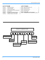
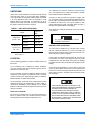
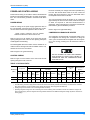
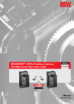
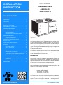
INSTALLATION
INSTRUCTION
SPLIT-SYSTEM
CONDENSING UNITS
AIR COOLED
MODELS: H3CE180 & 240
TABLE OF CONTENTS
GENERAL . . . . . . . . . . . . . . . . . . . . . . . . . . . . . . . . . . 1
REFERENCE . . . . . . . . . . . . . . . . . . . . . . . . . . . . . . . . 1
LIMITATION . . . . . . . . . . . . . . . . . . . . . . . . . . . . . . . . . 3
LOCATION . . . . . . . . . . . . . . . . . . . . . . . . . . . . . . . . . . 3
O
ROOF-TOP LOCATIONS . . . . . . . . . . . . . . . . . . . . . . . 3
O
GROUND LEVEL LOCATIONS . . . . . . . . . . . . . . . . . . 3
O
RIGGING AND HANDLING . . . . . . . . . . . . . . . . . . . . . 4
POWER AND CONTROL WIRING . . . . . . . . . . . . . . . . 5
CONTROL WIRING . . . . . . . . . . . . . . . . . . . . . . . . 5
COMPRESSOR CRANKCASE HEATER . . . . . . . 5
REFRIGERANT PIPING . . . . . . . . . . . . . . . . . . . . . . . . 8
GENERAL GUIDELINES . . . . . . . . . . . . . . . . . . . 8
GENERAL
EXTENDING THE SERVICE PORTS . . . . . . . . . . . . 11
INSTALLATION . . . . . . . . . . . . . . . . . . . . . . . . . . . . . 11
EVACUATION AND CHARGING . . . . . . . . . . . . . . . . 12
STARTUP . . . . . . . . . . . . . . . . . . . . . . . . . . . . . . . . . . 15
PRE-START CHECK . . . . . . . . . . . . . . . . . . . . . . 15
INITIAL STRART-UP . . . . . . . . . . . . . . . . . . . . . . 15
These condensing units are designed for outdoor installation on a roof
or at ground level. Every unit is completely piped and wired at the factory and is shipped ready for immediate installation. Only the liquid and
suction lines to the evaporator coil, the filter drier, the control wiring and
the main power wiring are required to complete the installation. Each
unit is dehydrated, evacuated, leak tested and pressure tested at 450
psig before being pressurized with a holding charge of refrigerant-22
for shipment and/or storage.
OPERATION . . . . . . . . . . . . . . . . . . . . . . . . . . . . . . . . 15
FIRST STAGE OF COOLING . . . . . . . . . . . . . . . 15
ANTI-SHORT CYCLE TIME DELAY RELAYS . . 15
COMPRESSOR CONTROL MODULE . . . . . . . . 16
LOW OR HIGH PRESSURE LOCK OUT
OPERATION . . . . . . . . . . . . . . . . . . . . . . . . . . . . 16
RESETTING THE LOCK OUT . . . . . . . . . . . . . . 16
All controls are located in the front of the unit and are readily accessible
for maintenance, adjustment and service. All wiring (power and control)
can be made through the front of the unit.
REFERENCE
This instruction covers the installation and operation of the basic condensing unit. For information on the installation and operation of the
evaporator blower units, refer to instruction Form No. 035-16603-000.
MAINTENANCE . . . . . . . . . . . . . . . . . . . . . . . . . . . . . 17
All accessories come with a separate Installation Manual.
Refer to Parts Manual for complete listing of replacement parts on this
equipment. All forms may be ordered from:
Standard Register
Norman, Oklahoma 73069
Toll Free Tel.: 877-318-9675
Toll Free Fax: 877-379-7920
INSPECTION
As soon as a unit is received, it should be inspected for possible damage during transit. If damage is evident, the extent of the damage
should be noted on the carrier’s freight bill. A separate request for
inspection by the carrier’s agent should be made in wiriting.
CAUTION: SAVE THIS MANUAL
035-15470-000 Rev A (1000)
035-15470-000 Rev A (1000)
LIST OF FIGURES
LIST OF TABLES
FIGURE 1 :
FIGURE 2 :
FIGURE 3 :
FIGURE 4 :
FIGURE 5 :
FIGURE 6 :
FIGURE 7 :
FIGURE 8 :
TABLE 1: UNIT APPLICATION DATA . . . . . . . . . . . . . . . . 3
TABLE 2: PHYSICAL DATA . . . . . . . . . . . . . . . . . . . . . . . . 5
TABLE 3: ELECTRICAL DATA . . . . . . . . . . . . . . . . . . . . . . 6
TABLE 4: SUCTION LINES . . . . . . . . . . . . . . . . . . . . . . . . . 9
TABLE 5: LIQUID LINES . . . . . . . . . . . . . . . . . . . . . . . . . . 10
TABLE 6: REFRIGERANT-22 LINE CHARGE. . . . . . . . . . 10
TABLE 7: CONDENSING UNIT COOLING CAPACITIES . 10
CENTER OF GRAVITY . . . . . . . . . . . . . . . 4
TYPICAL RIGGING . . . . . . . . . . . . . . . . . . 4
TYPICAL FIELD WIRING . . . . . . . . . . . . . . 6
UNIT DIMENSIONS AND CLEARANCES . 7
POINT LOADS. . . . . . . . . . . . . . . . . . . . . . 8
EXTENDING THE SERVICE PORTS . . . . 13
CHARGING CURVE FOR HCE180. . . . . 14
CHARGING CURVE FOR HCE240. . . . . 14
PRODUCT NOMENCLATURE
H
3
C
E
1
8
0
PRODUCT CATEGORY
A
2
5
VOLTAGE CODE
H = Split-System Condensing Unit
25 = 208/230-3-60
46 = 460-3-60
58 = 575-3-60
PRODUCT
GENERATION
3 = 3rd Generation
NOMINAL COOLING
CAPACITY
180 = 15 Tons
240 = 20 Tons
FACTORY INSTALLED HEAT
A = Not Applicable
PRODUCT IDENTIFIER
CE = Section
2
Unitary Products Group
035-15470-000 Rev A (1000)
LIMITATIONS
These units must be installed in accordance with all national
and local safety codes. If no local codes apply, installation
must conform with the appropriate national codes. See Table
1 for Unit Application Data. Units are designed to meet
National Safety Code Standards. If components are to be
added to unit to meet local codes, they are to be installed at
the dealer’s and/or the customer’s expense.
TABLE 1: UNIT APPLICATION DATA
MODEL
Voltage Variation*Min. / Max
Ambient Air on
Condenser Coil
Min. / Max
*.
180 & 240
MBH
208/230-3-60
187 / 252
460-3-60
432 / 504
575-3-60
540 / 630
Standard
35°F / 115°F
with Head Pressure Control
0°F / 115°F
Rated in accordance with ARI Standard 110, utilization range “A”.
LOCATION
Use the following guidelines to select a suitable location for
these units.
1.The condensing unit is designed for outdoor installation
only. The condenser fans are the propeller type and are not
suitable for use with duct work.
2.The condensing unit and the evaporator blower should be
installed as close together as possible and with a minimum
number of bends in the refrigerant piping. Refer to “REFRIGERANT PIPING” for additional information.
3.The condensing unit should not be installed where normal
operating sounds may be objectionable. On either rooftop or
ground level installations, rubber padding can be applied
between the base rails and their supports to lessen any transmission of vibration.
ROOF-TOP LOCATIONS
Be careful not to damage the roof. Consult the building contractor or architect if the roof is bonded. Choose a location
with adequate structural strength to support the unit.
Unitary Products Group
The condensing unit must be mounted on solid level supports. The supports can be channel iron beams or wooden
beams treated to reduce deterioration.
A minimum of two (2) beams are required to support each
unit. The beams should: (1) Be positioned perpendicular to
the roof joists. (2) Extend beyond the dimensions of the unit
to distribute the load on the roof. (3) Be capable of adequately supporting the entire unit weight. Refer to Figure 1
and Table 2 for load distribution and weights.
These beams can usually be set directly on the roof. Flashing
is not required.
On bonded roofs, check for special
installation requirements.
GROUND LEVEL LOCATIONS
The units must be installed on a one-piece level concrete
slab with a minimum thickness of 4 inches. The length and
width should be at least 6 inches greater than the units overall base dimensions. Refer to Figure 4.
Footers under the slab that extend below the frost line are
recommended. Any strain on the refrigerant lines may cause
a refrigerant leak. The slab should not be tied to the building
foundation because noise and vibration will telegraph into the
building.
A unit can also be supported by concrete piers. These piers
should (1) extend below the frost line, (2) be located under
the unit’s four corners, and (3) be sized to carry the entire unit
weight. Refer to Figure 1 and Table 2 for the center of gravity
and unit weight
CARE SHOULD BE TAKEN TO PROTECT THE
UNIT FROM TAMPERING AND UNAUTHORIZED
PERSONS FROM INJURY.SCREWS ON
ACCESS PANELS WILL PREVENT CASUAL
TAMPERING. ADDITIONAL SAFETY PRECAUTIONS SUCH AS FENCES AROUND THE UNIT
OR LOCKING DEVICES ON THE PANELS MAY
BE ADVISABLE. CHECK LOCAL AUTHORITIES
FOR SAFETY REGULATIONS.
3
035-15470-000 Rev A (1000)
.
Unit
Rig the unit by attaching chain or cable slings with hooks to
the round lifting holes provided in the base rails.
Dim. (in.)
A
B
180 Mbh
16
32
240 Mbh
16
32
SPREADERS, LONGER THAN THE LARGEST
DIMENSION ACROSS THE UNIT, MUST BE
USED ACROSS THE TOP OF THE UNIT.
BEFORE LIFTING A UNIT, MAKE SURE THAT
ITS WEIGHT IS DISTRIBUTED EQUALLY ON
THE CABLES SO THAT IT WILL LIFT EVENLY.
Units may also be moved or lifted with a fork-lift from the
front, rear or the compressor end only through the slotted
openings provided in the base rails.
FIGURE 1 : CENTER OF GRAVITY
S P R E A D E R
B A R
W A R N IN G
B e fo r e liftin
m a k e s u re
is d is tr ib u te
th e c a b le s
lift e v e n ly .
g th e u
th a t its
d e q u a
s o th a t
n it,
w e ig h t
lly o n
it w ill
LENGTH OF FORKS MUST BE A MINIMUM OF
54” WHEN LIFTING FORM THE COMPRESSOR
END OF THE UNIT AND A MINIMUM OF 42”
WHEN LIFTING FROM THE FRONT OR REAR
OF THE UNIT.
Remove the nesting brackets from the four corners on top of
the unit. All screws that are removed to take these brackets
off must be replaced on the unit.
CLEARANCES
All units require certain minimum clearances for proper operation and service. Refer to Figure 4 for these clearances.
L IF T IN G
H O L E S
FIGURE 2 : TYPICAL RIGGING
DO NOT PERMIT OVERHANGING STRUCTURES OR SHRUBS TO OBSTRUCT CONDENSER AIR DISCHARGE.
RIGGING AND HANDLING
Exercise care when moving the unit. Do not remove any
packaging until the unit is near the place of installation.
4
Additional height may be required for snow clearance if winter operation is expected.
Unitary Products Group
035-15470-000 Rev A (1000)
POWER AND CONTROL WIRING
Install electrical wiring in accordance with the latest National
Electrical Code (NFPA Standard No. 70) and/or local regulations. The unit should be grounded in accordance with these
codes.
POWER WIRING
Check the voltage of the power supply against the data on
the unit nameplate. Check the size of the power wire, the disconnect switch and the fuses against the data on Table 3.
Route the necessary low voltage control wires (18 AWG min.)
from the TB1 terminal block inside of the unit control box
through this access opening to the room thermostat and to
the evaporator blower motor controller.
The room thermostat should be located on an inside wall
approximately 56" above the floor where it will not be subject
to drafts, sun exposure or heat from electrical fixtures or
appliances. Follow manufacturer’s instructions enclosed with
thermostat for general installation procedure.
Refer to Figure 3 for typical field wiring.
COMPRESSOR CRANKCASE HEATER
NOTE: Copper conductors must be installed
between the disconnect switch and the unit.
Refer to Figure 4 for the location of the power wire access
opening through the front of the unit. This opening will require
a field-supplied conduit fitting.
The compressor is equipped with a crankcase heater to prevent refrigerant from mixing with crankcase oil during the
“OFF” cycle. The heater will be energized when the compressor is not running providing the unit disconnect switch is
closed.
The field-supplied disconnect switch must be suitable for an
outdoor location. Although it should be installed near the unit,
do NOT secure it to the unit cabinet.
Refer to Figure 3 for typical field wiring.
DO NOT ATTEMPT TO START THE COMPRESSOR WITHOUT AT LEAST EIGHT HOURS OF
CRANKCASE HEAT OR COMPRESSOR DAMAGE CAN OCCUR.
CONTROL WIRING
Refer to Figure 4 for the location of the control wire access
opening through the front of the unit.
TABLE 2: PHYSICAL DATA
Condenser
Compressor*
Model Size
(Mbh)
Rating
(Tons)
24” Fan (Propeller)
Unit Weight
(lbs.)
Coil
†
Fan Motor
Cap.
(Stg’s.)
Qty.
Blades/
Pitch
(Deg.)
Nom.
CFM
Qty.
HP
RPM
Rotation
Fins
per
inch
Rows
Deep
Ship.
Oper.
Charge
(Refrigerant-22 lbs.oz.)
Holding‡
Oper**
180
15
2
2
3/32
10,800
2
1
1100
CCWLE
20
2
920
930
1-0
24-12
240
20
2
2
3/32
11,300
2
1
1100
CCWLE
20
2
970
990
1-0
32-13
*.
Compressor set consists of two Copeland Scroll compressors manifolded into a single refrigerant circuit.
†.
The ball bearing, 48 frame, single phase condenser fan motor have internal protection that is directly connected to the condenser
fans. Motor rotation is counter-clockwise when viewing the lead end, which is opposite the shaft end.
‡.
Holding charge is the amount in the unit as shipped from the factory.
**.
Operating refrigerant charge is for the condensing unit and the matching York air handler, but does not include the charge in the
interconnecting piping. See the refrigerant line charge table to determine the additional refrigerant charge required for the interconnecting piping.
Unitary Products Group
5
035-15470-000 Rev A (1000)
FIGURE 3 : TYPICAL FIELD WIRING
H 3 C E 1 8 0 /K 4 E U 1 8 0
3 -P H A S E
L IN E V O L T A G E
P O W E R S U P P L Y
3 -P H A S E
L IN E V O L T A G E
P O W E R S U P P L Y
D IS C O N N E C T S W IT C H E S
A N D F U S IN G B Y F IE L D
G R O U N D L U G (F O R
G R O U N D W IR E
IF R E Q U IR E D )
L 1
L 2
L 3
T B 1
C O N D .
S E C T IO N
T B 4
R
Y 1
X
Y 2
B
E V A P O R A T O R
B L O W E R M O T O R
C O N T A C T O R
2 4 V
L
C O M P R E S S O R 2 4 V
L O C K O U T S IG N A L
2 V A M A X .
R C
Y 2
Y 1
G
T H E R M O S T A T
2 T H 0 4 7 0 1 2 2 4
H 3 C E 2 4 0 /L 4 E U 2 4 0
3 -P H A S E
L IN E V O L T A G E
P O W E R S U P P L Y
L IQ U ID
S O L E N O ID
G R O U N D L U G (F O R
G R O U N D W IR E
IF R E Q U IR E D )
L 1
L 2
C
C O N D .
S E C T IO N
1
1
2
T B 4
X
L IN E
V A L V E S
L 3
T B 1
R
3 -P H A S E
L IN E V O L T A G E
P O W E R S U P P L Y
D IS C O N N E C T S W IT C H E S
A N D F U S IN G B Y F IE L D
Y 1
B
2
Y 2
E V A P O R A T O R
B L O W E R M O T O R
C O N T A C T O R
2 4 V
L
C O M P R E S S O R 2 4 V
L O C K O U T S IG N A L
2 V A M A X .
W
IR E IN A C C O R D A N C E W IT H A L L L O C A L
A N D N A T IO N A L E L E C T R IC A L C O D E S .
R C
Y 2
Y 1
G
L O W
L IN E
T H E R M O S T A T
2 T H 0 4 7 0 1 2 2 4
F IE L D
V O L T A G E
V O L T A G E
W
IR IN G :
C L A S S 2
C L A S S 1
W
W
N O T E :
2 S O L E N O ID M A Y N O T
P R E S E N T O N N E W E R
A IR H A N D L E R S .
B E
IR IN G
IR IN G
TABLE 3: ELECTRICAL DATA
COMPRESSOR* CONDENSER FAN MOTOR
MODEL
6
UNIT
POWER
SUPPLY
QTY
RLA
LRA
QTY
HP
UNIT
FLA
MINIMUM
CIRCUIT
AMPACITY
(AMPS)
MAXIMUM
FUSE
SIZE†
(AMPS)
MINIMUM
DISCONNECT SIZE‡
(AMPS)
HCE180A25
208/230/3/60
2
26.4
189
2
1
5.0
69.4
90
100
HCE180A46
460/3/60
2
13.9
94
2
1
2.6
36.5
50
60
HCE180A58
575/3/60
2
10.1
74
2
1
2.0
26.7
35
30
HCE240A25
208/230/3/60
2
37.4
278
2
1
5.0
94.2
125
100
HCE240A46
460/3/6/60
2
18.4
127
2
1
2.6
46.6
60
60
HCE240A58
575/3/60
2
15.2
100
2
1
2.0
38.6
50
60
Unitary Products Group
035-15470-000 Rev A (1000)
*.
The 208-230 V compressors and motors use a single tap for the entire range of voltages. The 208/230 V to 24 V transformers have different taps for 208 and 230 V.
†.
Dual element, time delay type.
‡.
Refer to article NEC/NFPA No. 70, articles 440-11,12 for information on minimum disconnect sizing.
FIGURE 4 : UNIT DIMENSIONS AND CLEARANCES
C O M P R E S S O R A N D
F A N M O T O R A C C E S S
E X T E R N A L P R E S S U R E
G A U G E F IT T IN G S
F A N M O T O R
A C C E S S
A IR
O U T
A IR
O U T
F
A IR
IN
F
O
E
E
O
A
F
C O N T R O L B O X
A C C E S S
O
4 4 -9 /3 2
5 -3 /4
C
B
D
2 4 -1 /2
1 2 -1 /8
3 9 - 7 /8
1 3 -1 /4
3 0 -3 /4
7 -1 /3 2
7 6 -7 /8
9 -1 /3 2
A P P R O X IM A T E
C E N T E R O F G R A V IT Y
B A C K
(C O IL E N D )
3 2
7 6 - 7 /8
1 6
3 9 - 7 /8
F R O N T
CONNECTION ENTRY
CONNECTION SIZE
15 Ton
20 Ton
Suction Line*
A
1/5/8 ID
2-1/8 ID
Liquid Line
B
5/8 OD
5/8 OD
Power Wiring
C
2-1/8 KO
2-1/8 KO
control Wiring
D
7/8 KO
7/8 KO
Accessory Wiring
E
7/8 KO
7/8 KO
Accessory Wiring
F
1-3/8KO
1-3/8 KO
*.
Suction line is a belled fitting
NOTE: All dimensions are in inches. They are subject to change
without notice. Certified dimensions will be provided upon
request.
Unitary Products Group
Overhead (Top)*
120”
Front (Piping and Access Panels
30”
Left Side
24”
Right Side
24”
Rear
24”
Bottom†
0”
*.
Units must be installed outdoors. Overhanging
structures or shrubs should not obstruct condenser air discharge.
†.
Adequate snow clearance must be provided
during winter operation.
7
035-15470-000 Rev A (1000)
UNIT
4-POINT LOAD (lbs)
TOTAL
A
B
C
D
180
930
325
218
155
232
240
990
346
232
165
247
*
)
+
,
FIGURE 5 : POINT LOADS
REFRIGERANT PIPING
GENERAL GUIDELINES
Many service problems can be avoided by taking adequate
precautions to provide an internally clean and dry system and
by using procedures and materials that conform with established standards.
Use hard drawn copper tubing where no appreciable amount
of bending around pipes or other obstructions is necessary.
Use long radius ells wherever possible with one exception—
short radius ells for the traps in all suction risers. If soft copper is used, care should be taken to avoid sharp bends which
may cause a restriction.
Pack fiberglass insulation and a sealing material such as permagum around refrigerant lines where they penetrate a wall
to reduce vibrations and to retain some flexibility.
Support all refrigerant lines at minimum intervals with suitable
hangers, brackets or clamps.
Braze all copper to copper joints with Silfos-5 or equivalent
brazing material. Do not use soft solder.
Insulate all suction lines with a minimum of 1/2" ARMAFLEX
or equal. Liquid lines exposed to direct sunlight and/or high
temperatures must also be insulated.
8
Never solder suction and liquid lines together. They can be
taped together for convenience and support purposes, but
they must be completely insulated from each other.
A filter-drier MUST be installed in the liquid line of every system to prevent dirt and moisture from damaging the system.
A properly-sized filter-drier is shipped with each condensing
unit for field installation near the evaporator coil. The filterdrier is shipped inside the unit control box.
INSTALLING A FILTER-DRIER DOES NOT ELIMINATE THE NEED FOR THE PROPER EVACUATION OF A SYSTEM BEFORE IT IS CHARGED.
A moisture indicating sight-glass may be field installed in liquid line(s) between the filter-drier and the evaporator coil.
The moisture indicating sight-glass can be used to check for
excess moisture in the system or used as visual means to
verify refrigerant charge.
Line sizing
When sizing refrigerant lines for a split-system air conditioner,
check the following: 1. Suction line pressure drop due to friction at full capacity, 2. Liquid line pressure drop due to friction
Unitary Products Group
035-15470-000 Rev A (1000)
at full capacity, 3. Suction line velocity for oil return at part
capacity, and 4. Liquid line pressure drop due to static head.
NEVER BASE REFRIGERANT LINE SIZES ON
THE OD OF THE SUCTION AND LIQUID CONNECTIONS ON THE UNIT.
Tables 4 and 5 list friction losses for both the suction and liquid lines on the system. Table 6 shows the amount of refrigerant charge required per foot of refrigerant line.
When the evaporator coil is below the condensing unit, the
suction line must be sized for both pressure drop and for oil
return. For certain piping arrangements, different suction line
sizes may have to be used. The velocity of the suction gas
must always be great enough to carry oil back to the compressor.
When the condensing unit is below the evaporator coil, the
liquid line must be designed for the pressure drop due to both
friction loss and vertical rise. If the total pressure drop
exceeds 40 psi, some refrigerant may flash before it reaches
the thermal expansion valve. This flashing will not only cause
erratic valve operation and poor system performance, but
could also damage the expansion valve.
Service Valves
These condensing units have service valves on the compressor suction line and on the liquid line leaving the condenser
coil.
The liquid and suction line service valves are shipped from
the factory front-seated and closed with the valve stem in the
maximum clockwise position.
The liquid and suction line service valves have a 1/4" male
flare access port for evacuating, charging and pressure
checking the system.
NEVER REMOVE A CAP FROM AN ACCESS
PORT UNLESS THE VALVE IS FULLY BACKSEATED WITH ITS VALVE STEM IN THE MAXIMUM COUNTER-CLOCKWISE POSITION
BECAUSE THE REFRIGERANT CHARGE WILL
BE LOST. ALWAYS USE A REFRIGERATION
VALVE WRENCH TO OPEN AND CLOSE THESE
SERVICE VALVES.
TABLE 4: SUCTION LINES*
MODEL DESIGNATION
Full Capacity
NOMINAL
CAPACITY
(TONS)
REFRIGERANT
FLOW RATE
15
45
†
(LBS./MIN.)
180 Mbh
Part Capacity
Full Capacity
8-1/2
20
25.5
60
240 Mbh
Part Capacity
10
30
TYPE L COPPER TUBING
(INCHES O.D.)
REFRIGERANT
GAS VELOCITY
(FT./MIN.)
FRICTION LOSS‡ (PSI/
100 FT.)
1-5/8
2300
2.5
2-1/8
1360
0.6
1-5/8
1150
0.7
2-1/8
770**
0.2
1-5/8
3120
4.3
2-1/8
1800
1.2
2-1/8
1200
0.4
1-5/8
1560
1.2
2-1/8
900**
0.3
2-5/8
600**
0.1
*.
All horizontal suction lines should be pitched at least 1 inch every 20 ft. in the direction of the refrigerant flow to aid the
return of oil to the compressor. Every vertical riser greater than 25 ft. in height should have a “P” trap at the bottom to facilitate the return of oil to the compressor. Use short radius fittings for these traps.
†.
Based on Refrigerant-22 at the nominal capacity of the condensing unit, a suction temperature of 40°F and a liquid temperature of 105°F.
‡.
Although suction lines should be sized for a friction loss equivalent to a 2°F change in saturation temperature (or approximately 3 PSI), sizing the lines for the proper return of oil is more important. These friction losses do not include any allowances for valves or fittings.
**.
Since the refrigerant gas velocity may be too low to maintain good oil return up a vertical riser, use the next smaller size.
The larger size may be used for horizontal runs for a smaller pressure drop.
Unitary Products Group
9
035-15470-000 Rev A (1000)
TABLE 5: LIQUID LINES
*.
MODEL DESIGNATION
NOMINAL
CAPACITY
(TONS)
REFRIGERANT
FLOW RATE
180 Mbh
15
45
240 Mbh
20
60
PRESSURE DROP*
TYPE L COPPER TUBING
(INCHES O.D.)
FRICTION
(PSI/100 FT.)
3/4
4.7
7/8
2.2
3/4
8.0
7/8
3.5
VERTICAL RISE
(PSI/FT.)
0.5
0.5
The total pressure drop of the liquid line for both friction and vertical rise must not exceed 40 PSI. If the pressure drop exceeds 40
PSI, the liquid refrigerant could flash before it reaches the expansion valve. This flashing will only cause erratic valve operation
and poor system performance, but could also damage the expansion valve.
TABLE 6: REFRIGERANT-22 LINE CHARGE*
Liquid Line Inches, O.D.†
Suction Line Inches, O.D.†
5/8
0.113 lb./ft.
7/8
0.237 lb./ft.
1-5/8
0.018lb./ft.
2-1/8
0.031 lb./ft.
2-5/8
0.047 lb./ft.
*.
Charges are based on 40°F suction temperature and a 105°F liquid
temperature
†.
Type “L” copper tubing
Note: Add the operating charge of the condensing unit, the evaporator
coil and the refrigerant lines to determine the total refrigerant charge
of the system.
TABLE 7: CONDENSING UNIT COOLING CAPACITIES AND POWER REQUIREMENTS
Model
180
240
10
Compressor Suction
Pressure
(psig)
Saturated
Temp
(°F)
54.9
Ambient Temperature Entering Condenser Coil (°F)
65
75
85
95
105
115
MB*
kW†
MBH
kW
MBH
kW
MBH
kW
MBH
kW
MBH
kW
30
165
12.3
157
13.4
150
14.8
142
16.3
134
18.1
126
19.9
61.6
35
181
12.5
172
13.6
164
15.0
156
16.5
147
18.3
138
20.2
68.5
40
196
12.7
188
13.9
179
15.3
170
16.7
160
18.6
151
20.4
76.0
45
212
12.9
204
14.1
194
15.5
184
17.0
174
18.9
164
20.8
84.0
50
231
13.2
220
14.3
210
15.8
199
17.3
188
19.1
177
21.0
54.9
30
228
17.3
217
19.2
206
21.1
195
23.4
183
25.9
172
28.5
61.6
35
248
17.7
237
19.6
225
21.5
213
23.8
200
26.4
188
29.0
68.5
40
269
18.1
257
20
244
21.9
231
24.3
218
26.9
204
29.6
76.0
45
291
18.5
277
20.5
264
22.4
250
24.8
236
27.5
222
30.3
84.0
50
313
19.0
299
21
284
23.0
269
25.3
254
28.1
239
30.9
*.
Capacities are gross ratings
†.
Power is for the condensing unit only
Unitary Products Group
035-15470-000 Rev A (1000)
EXTENDING THE SERVICE PORT
1.
Loosen the screws that secure the service ports in shipping position.
2.
Push the service ports through the corner post.
3.
Tighten the screws to secure the service ports for installation.
INSTALLATION
Since the condensing units are shipped with a holding charge
of Refrigerant-22, they can be checked for a refrigerant leak
by depressing the stem on either of the service ports that
extend through the cabinet. As soon as some internal pressure is relieved release the stem. DO NOT release the entire
holding charge.
5.
Carefully clean the internal surfaces of the above. Any
particles left on these surfaces may lead to a future system malfunction.
NOTE: Use only copper tubing that has been especially cleaned and dehydrated for refrigerant use. If
the tubing has been open for an extended period of
time, it should be cleaned before being used.
The liquid line connections can now be brazed while maintaining a minimum flow of dry nitrogen through the piping as
follows:
1.
Remove the cap from the 1/4" access port on the liquid
line service valve.
2.
Connect a supply of dry nitrogen to this access port
NOTE: The filter-drier should be installed in the liquid line as close to the evaporator coil as possible.
If the unit has already lost its holding charge, it should be leak
tested and the necessary repairs should be made. If the unit
has maintained its holding charge, you can assume that it
has no leaks and proceed with the installation.
Do not allow the filter-drier to be exposed to the
atmosphere for an extended period of time. Once it
absorbs moisture from the atmosphere, it loses its
effectiveness.
The matched air handlers are shipped with a small
R-22 charge and the should be checked for leaks
before installation.
DRY NITROGEN SHOULD ALWAYS BE SUPPLIED THROUGH A CONNECTION WHILE IT IS
BEING BRAZED OR UNBRASED BECAUSE THE
TEMPERATURE REQUIRED TO MAKE OR
BREAK A BRAZED JOINT IS SUFFICIENTLY
HIGH TO CAUSE OXIDATION OF THE COPPER
UNLESS AN INERT ATMOSPHERE IS PROVIDED. THE FLOW OF NITROGEN SHOULD BE
CONTINUED UNTIL THE JOINT HAS COOLED.
When making a braze connection, wrap a wet rag around all
tubing inside the unit to help prevent damage to other components.
1.
Drill a small hole through the sealing cap or disc in both
the liquid and suction connection. If there is a pressure
release, the evaporator has no leaks and you can proceed with installation. If the charge has been lost, the
coils should be leak tested and the necessary repairs
made.
2.
Move the dry nitrogen supply from the access port on the
liquid line service valve of the condensing unit to the hole
through the suction disc on the evaporator coil.
3.
Unbraze the coil’s liquid line disc while maintaining a flow
of dry nitrogen across the connection and through the
hole in the liquid line disc.
NOTE: If the liquid line has a solenoid valve, the
valve should be opened manually to permit the nitrogen to flow freely.
THE DRY NITROGEN SHOULD ALWAYS BE
SUPPLIED THROUGH A PRESSURE REGULATING VALVE.
4.
Burnish the external surfaces of the liquid connection on
the condensing unit and the end of the field-supplied piping for the liquid line.
NOTE: Clean surfaces are essential for a wellbrazed connection.
Unitary Products Group
4.
After the disc has been removed, burnish the external
surfaces and clean the internal surfaces as outlined
above.
5.
Move the dry nitrogen supply back to the access port on
the liquid line service valve.
6.
Braze the liquid line to the liquid connection on the evaporator coil while maintaining a minimum flow of dry nitrogen through the liquid line, the evaporator coil and the
hole in the suction disc.
11
035-15470-000 Rev A (1000)
7.
Unbraze the disc on the suction connection of the evaporator coil while maintaining the flow of dry nitrogen.
8.
After the disc has been removed, burnish the external
surfaces and clean the internal surfaces as outlined
above.
The suction piping can now be brazed to the suction connection on the evaporator coil while maintaining a minimum flow
of dry nitrogen.
DO NOT ATTEMPT TO START THE COMPRESSOR WITHOUT AT LEAST 8 HOURS OF
CRANKCASE HEAT OR COMPRESSOR DAMAGE WILL OCCUR.
Before brazing the suction line to the condensing unit:
1.
Move the dry nitrogen supply to the access port on the
suction service valve of the condensing unit.
2.
Burnish the external surfaces and clean the internal surfaces of both the suction connection and the suction piping.
To continue charging refrigerant, open the liquid and the suction line service valves fully. Turn the stem of the liquid service valve clockwise 1/4 turn to open its access port for
reading pressure.
The suction line can now be brazed to the suction connection
on the condensing unit while maintaining the flow of dry nitrogen.
Start the compressor (after 8 hours of crankcase heat), turn
the stem of the suction line service valve clockwise 1/4 turn to
open its service port and continue to charge refrigerant gas
through this suction access port until you meet the conditions
shown on the charging curve, Fig. 8.
After the liquid and suction lines have been installed, the system should be evacuated and charged.
Open the liquid and vapor line service valves fully to close
their access ports after the system has been charged.
EVACUATION AND CHARGING
Alternate Charging Methods
With the liquid and suction line service valves closed, connect a vacuum pump through a charging manifold to the
access ports on both the liquid and suction line service
valves.
NOTE: The vacuum pump connection should be
short and no smaller than 3/8" O.D.
The refrigerant lines and the evaporator coil can now be
evacuated to 500 microns without disturbing the charge in the
condenser coil or the compressor.
After proper evacuation and dehydration, charge refrigerant
through the access port on the liquid line service valve allowing the vacuum to draw in as much refrigerant as possible.
DO NOT CHARGE LIQUID REFRIGERANT
THROUGH THE COMPRESSOR SUCTION
CONNECTION.
12
If you are starting a unit when the ambient temperature is
higher or lower than those shown in Fig. 8, either of the following methods may be used.
Method 1: Determine the total weight of the refrigerant for the
total system by adding the required charge for the outdoor
unit, the indoor unit and the refrigerant lines using information
in Tables 2 (Physical Data) and 6 (Refrigerant Line Charge).
Using the charging procedures outlined above, weigh the
required amount of refrigerant charge into the unit.
Method 2: Install a field supplied moisture indicating sight
glass in the liquid line between the filter-drier and the evaporator coil.
Using the charging procedure outlined above, charge refrigerant until the moisture indicating sight glass is clear. Add
approximately 2 extra pounds of refrigerant to assure a liquid
refrigerant seal at the expansion valve under all operating
conditions. Block the flow of the condenser air, if necessary,
to assure a head pressure of 280 psig during the charging
procedure.
Note: The installer should return to the job to verify
the operating charge when the ambient temperature
is within the conditions shown in Fig. 8.
Unitary Products Group
035-15470-000 Rev A (1000)
SERVICE PORTS IN SHIPPING POSITION
COPPER
UNIT WALL
2 SCREWS
COPPER
TUBE
CORNER
POST
UNIT
WALL
SIDE VIEW
SERVICE PORTS IN INSTALLED POSITION
LOOSEN
SCREWS
COPPER
2 SCREWS
CORNER
SIDE VIEW
(AS SHIPPED)
POST
PUSH SERVICE
PORTS THROUGH
UNIT
WALL
TOP VIEW
CORNER POST
TIGHTEN SCREWS
(
SERVICE PORTS
EXTENDED
)
SIDE VIEW
(
SERVICE PORTS
EXTENDED
)
FIGURE 6 : EXTENDING THE SERVICE PORTS
Unitary Products Group
13
035-15470-000 Rev A (1000)
Charging Curve
H*CE180
400
115°F Ambient
Discharge Pressure
350
105°F Ambient
300
95°F Ambient
85°F Ambient
250
75°F Ambient
200
57
62
67
72
77
82
87
92
97
87
92
97
Suction Pressure
FIGURE 7 : CHARGING CURVE FOR HCE180
Charging Curve
H*CE240
400
115°F Ambient
Discharge Pressure
350
105°F Ambient
300
95°F Ambient
85°F Ambient
250
75°F Ambient
200
57
62
67
72
77
82
Suction Pressure
FIGURE 8 : CHARGING CURVE FOR HCE240
14
Unitary Products Group
035-15470-000 Rev A (1000)
STARTUP
2.
Move the system switch on the thermostat to the AUTO
or COOL position.
CRANKCASE HEATER
3.
Reduce the setting of the room thermostat to energize
the compressor.
4.
Check the operation of the evaporator unit per the manufacturer’s recommendations.
5.
With an ammeter, check the compressor amps against
the unit data plate.
6.
Check for refrigerant leaks.
7.
Check for any abnormal noises and/or vibrations, and
make the necessary adjustments to correct (e.g. fan
blade(s) touching shroud, refrigerant lines hitting on
sheet metal, etc.)
8.
After the unit has been operating for several minutes,
shut off the main power supply at the disconnect switch
and inspect all factory wiring connections and bolted surfaces for tightness.
The crankcase heater must be energized at least 8 hours
before starting the compressor. To energize the crankcase
heater, the main disconnect switch must be closed. During
this 8 hour period, the system switch on the room thermostat
must be “OFF” to prevent the compressor from starting.Make
DO NOT ATTEMPT TO START THE COMPRESSOR WITHOUT AT LEAST 8 HOURS OF
CRANKCASE HEAT OR COMPRESSOR DAMAGE CAN OCCUR
sure that the bottom of the compressor is warm to the touch
to prove crankcase heater operation.
PRE-START CHECK
Before starting the unit, complete the following check list:
1.
Have sufficient clearances been provided?
2.
Has all foreign matter been removed from the interior of
the unit (tools, construction or shipping materials, etc.)?
3.
Have the condenser fans been rotated manually to
check for free rotation?
4.
Are all wiring connections tight?
5.
Does the available power supply agree with the nameplate data on the unit?
6.
Is the control circuit transformer set for the proper voltage?
7.
Have the fuses, disconnect switch and power wire been
sized properly?
8.
Are all compressor hold-down nuts properly secured?
9.
Are any refrigerant lines touching each other or any
sheet metal surface? Rubbing due to vibration could
cause a refrigerant leak.
10. Are there any visible signs of a refrigerant leak, such as
oil residue?
11. Is any electrical wire laying against a hot refrigerant line?
INITIAL START-UP
1.
OPERATION
First stage of cooling
A call for cooling at terminal Y1 energizes relay RY1. Relay
RY1 closes contacts RY1-1, energizing time delay relay 3TR.
If time delay relay 3TR is satisfied as described below, it will
energize its output terminal Y2, which is connected to compressor 1 control module terminal M1.
If the compressor 1 control module is satisfied as described
below, it will apply power to terminal 7 of low or high pressure
lock out relay (LOR) contacts. See a description of the LOR
operation below. If the LOR coil is not energized (not locked
out), the LOR contacts will be closed, energizing contactor
1M, which powers compressor 1 and condenser fan motor 1.
When 1M is energized on H3CE240 units, auxiliary contact
1M-AC2 is closed, powering terminal 1 for opening the stage
1 solenoid in air handlers which feature a stage 1 solenoid.
If the low ambient temperature switch TLA is closed, it will
allow condenser fan 2 contactor 3M to energize. TLA opens
as the temperature falls below 50 F and closes as the ambient rises above 60 F. TLA is used on the H3CE180, not the
H3CE240.
Anti-short Cycle Time Delay Relays 3TR and 4TR
Relay 3TR, which serves compressor 1 control, has an
adjustable low voltage lock out which is set at 20V in the factory. The voltage applied to 3TR must be above its lock out
setting and 5 minutes must elapse since the relay was last
energized before it will energize its output terminal Y2. Relay
4TR is identical but it serves compressor 2 control.
Supply power to the unit through the disconnect switch
at least 8 hours prior to starting the compressor.
Unitary Products Group
15
035-15470-000 Rev A (1000)
Compressor Control Module
If the compressor control module terminals L1 (or T1) and L2
(or T2) have 24 V applied and the internal compressor temperature lock out is inactive, the internal switch connecting
M1 and M2 will be closed. M1 to M2 will open if one of the
compressor’s internal temperature sensors exceeds its limit.
M1 to M2 stays open for 30 minutes after a internal temperature limit is exceeded. The 30 minute lock out may be reset
prior to the 30 minutes expiring by removing power to the
control module terminals L1 and L2. During normal operation,
each compressor control module should always be powered
at the L1 and L2 terminals, whether there is a call for cooling
or not.
If the unit does not resume operation after the anti-short cycle
timer expires or if it continues to lock out after resuming operation, call a service technician to diagnose and repair the
unit.
REPEATEDLY RESETTING THE LOCK OUT
MAY CAUSE DAMAGE TO THE UNITS
Second Stage of Cooling
Low or High Pressure Lock Out Operation
If the lock out circuit path is opened during a call for cooling,
the lock out relay (LOR) coil will energize, opening LOR-1
contacts and disabling all compressor operation. The lock out
circuit path is open if:
• the lock out relay contacts LOR-1 are open, OR
• the low pressure switch LP is open AND the low
pressure switch bypass timer contacts 1TR-1 are
open, OR
• the high pressure switch HP is open
Once the LOR coil has been energized, it remains energized,
locking out cooling operation until the call for cooling has
been removed. When Y1 is returned to 0 volts, the LOR coil
is no longer energized, closing the LOR-1 contacts and
removing the lock out.
The low pressure bypass timer 1TR leaves the 1TR-1 contacts closed upon the start of a call for cooling until its 90 second (nominal) timer has expired. This bypasses the low
pressure switch during start up. After the time delay has
elapsed, 1TR-1 contacts are opened, once again allowing low
pressure to trigger the lock out circuit if the low pressure
switch opens.
The second stage of cooling will only be enabled if the first
stage of cooling is on, closing auxiliary contact 1M-AC1. A
call for cooling at terminal Y2 energizes Relay RY2, closing
contact RY2-1, and energizing time delay relay 4TR if contact
1M-AC1 is closed. If time delay relay 4TR is satisfied, it will
energize its output terminal Y2, which is connected to compressor 2 control module terminal M1.
If the compressor 2 control module is satisfied, it will energize
time delay relay TDR. After 4 seconds, TDR energizes compressor 2 contactor 2M. When 2M is energized on H3CE240
units, auxiliary contact 2M-AC1 is closed, powering terminal 2
for opening the stage 2 solenoid in air handlers which feature
a Stage 2 solenoid.
Low Ambient Cooling
The following accessories are available to provide low ambient operation to 0°F:
2LA04704225
208/230 VOLTS
2LA04704346
460 VOLTS
2LA04704458
575 VOLTS
SAFETY FEATURES
1.
The compressor is protected against over current and
excessive temperature as described in the Sequence of
Operation.
During a lock out, the LOR-2 contacts are closed, energizing
the X terminal on the terminal board for lighting a lock out
warning light.
2.
The compressor is equipped with a crankcase heater to
discourage refrigerant migration into the compressor
sump during the “OFF” cycle.
Resetting the Lock Out
3.
The condenser fan motors have auto-reset internal protection.
4.
The secondary of every transformer is grounded.
5.
Every unit is protected by high and low-pressure controls.
The lock out may be reset by:
•Turning the thermostat switch to OFF, or
• Momentarily adjusting the cooling set point to its maximum allowed value.
16
Unitary Products Group
035-15470-000 Rev A (1000)
DO NOT ATTEMPT TO START THE COMPRESSOR WITHOUt AT LEAST EIGHT HOURS OF
CRANKCASE HEAT OR COMPRESSOR DAMAGE WILL OCCUR.
SECURE OWNER’S APPROVAL
When the system is functioning properly, secure the owner’s
approval. Show him the location of all disconnect switches
and thermostat. Teach him how to start and stop the unit and
how to adjust temperature settings within the limitations of
the system.
MAINTENANCE
CLEANING CONDENSER SURFACE
Dirt should not be allowed to accumulate on the condenser
coils or other parts in the condenser air circuit. Clean as often
as necessary with a brush, vacuum cleaner attachment or
other suitable means.
LUBRICATION
The fan motors for these condensing units are equipped with
factory lubricated and sealed ball bearings. They do not
require any maintenance.
COMPRESSOR REPLACEMENT
Contact the local UPG Distribution Center for compressor or
parts.
Unitary Products Group
17
035-15470-000 Rev A (1000)
NOTES:
18
Unitary Products Group
035-15470-000 Rev A (1000)
Unitary Products Group
19
Subject to change without notice. Printed in U.S.A.
Copyright © by Unitary Products Group 2000. All rights reserved.
Unitary
Product
Group
035-15470-000 Rev A (1000)
Supersedes: 550.23-N6Y
5005
York
Drive
Norman
OK
73069