1
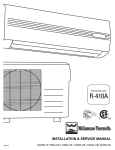
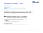
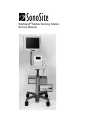
SiteStand® Mobile Docking Station
Service Manual
Manufactured for
SonoSite, Inc.
21919 30th Drive SE
Bothell, WA 98021-3904
USA
Telephone: 1-888-482-9449 or +1-425-951-1200
Fax: +1-425-951-1201
SonoSite European Headquarters
Baystrait House, Station Road
Biggleswade SG18 8AL
UK
Telephone: +44-1767-313-117
Fax: +44-1767-312-400
CAUTION:
` United States federal law restricts this device to sale by or on the order of a physician.
“SiteCharge,” “SitePack,” “SiteStand,” and “SonoHeart,” are trademarks of SonoSite, Inc.
VELCRO is a registered trademark of Velcro Industries B.V.
Non-SonoSite product names may be trademarks or registered trademarks of their respective owners.
SonoSite products may be covered by one or more of the following U.S. patents: 4454884, 4462408, 4469106, 4474184,
4475376, 4515017, 4534357, 4542653, 4543960, 4552607, 4561807, 4566035, 4567895, 4581636, 4591355, 4603702,
(4607642), 4644795, 4670339, 4773140, 4817618, 4883059, 4887306, 5016641, 5050610, 5095910, 5099847, 5123415,
5158088, 5197477, 5207225, 5215094, 5226420, 5226422, 5233994, 5255682, (5275167), 5287753, 5305756, 5353354,
5365929, 5381795, 5386830, 5390674, 5402793, (5,423,220), 5438994, 5450851, 5456257, 5471989, 5471990, 5474073,
5476097, 5479930, 5482045, 5482047, 5485842, 5492134, 5517994, 5529070, 5546946, 5555887, 5603323, 5606972,
5617863, (5634465), 5634466, 5636631, 5645066, 5648942, 5669385, (5706819), 5715823, 5718229, 5720291, 5722412,
5752517, 5762067, 5782769, 5800356, 5817024, 5833613, 5846200, 5860924, 5893363, 5916168, 5951478, 6036643,
6102863, 6104126, 6113547, 6117085, 6142946, 6203498 B1, D0280762, D0285484, D0286325, D0300241, D0306343,
D0328095, D0369307, D0379231. Other patents pending.
P02733-01
03/02
Copyright © 2002 by SonoSite, Inc.
All rights reserved. Printed in the USA.
iii
iv
Table of Contents
1
Introduction
1
1.1
SiteStand mobile docking station..............................................1
1.2
SiteStand System Display .........................................................1
1.3
Setup and Operation..................................................................2
1.4 Specifications............................................................................3
1.4.1 SiteStand mobile docking station .......................................3
1.4.2 SiteStand mobile docking station Display..........................3
1.4.2.1 Display Type ..................................................................3
2
3
Safety
5
2.1
Electrical Safety ........................................................................5
2.2
Equipment Protection................................................................6
2.3
Electrical Safety Testing ...........................................................6
2.4
Biological Safety.......................................................................7
Servicing the SiteStand
9
3.1 Introduction...............................................................................9
3.1.1 Contacting SonoSite Technical Support.............................9
3.2
Troubleshooting the SiteStand mobile docking station ............9
3.3 Disassembling the SiteStand mobile docking station .............11
3.3.1 Required Materials and Equipment..................................11
3.3.2 Replacing the Sleeve Assembly and the Docking PCBA 11
3.3.3 Replacing the Foot Pedal..................................................11
3.3.4 Repairing or Replacing the Front Panel Connectors
and the Power Supply12
3.3.5 Replacing the SiteStand station Fuse ...............................13
3.4 SiteStand Mobile Docking Station Performance Tests...........14
3.4.1 Setup.................................................................................14
3.4.2 AC Power Verification .....................................................14
3.4.3 Docking Video .................................................................14
3.4.4 RS-232..............................................................................14
3.4.5 Printer Interface................................................................14
3.4.6 Audio Tone.......................................................................14
SiteStand Mobile Docking Station Service Manual
v
A
Schematic and Parts List
15
A.1 Schematic and Wiring Diagram..............................................15
A.2 Replacement Parts List ...........................................................15
A.3 Ordering Replacement Parts ...................................................15
A.4 Cabling Diagram.....................................................................16
A.5 Schematic Diagram, Docking Stand PCB ..............................20
A.6 SiteStand Station Assembly....................................................21
A.7 SiteStand Station Sleeve Assembly ........................................24
B
vi
Service Event Report
25
SiteStand Mobile Docking Station Service Manual
CHAPTER
1
Introduction
Before servicing the SiteStand® mobile docking station (SiteStand), read and be
familiar with the information in this manual.
1.1
SiteStand mobile docking station
The SiteStand station (Figure 1.1) does the following:
The SiteStand® mobile docking station (SiteStand) does the following:
• Provides a mobile, ergonomic work surface with height and angle adjustment
• Holds the SonoSite system, two transducers, a printer, and certain accessories
• Charges the system battery and consolidates the following peripheral
connections: two video out, an audio out, an RS-232C, a printer control, and
two AC mains IEC power
• Offers a connection to the PC to download images
• Provides a locking feature to secure system against theft
1.2
SiteStand System Display
The SiteStand may include an optional flat panel display with the following
features:
• A high resolution display
• An additional video display for patients, students, consulting professionals or
others who require shared images
• Compatibility with all SiteStands
• Convenient display positioning with an articulating arm
• Worldwide power and video
SiteStand Mobile Docking Station Service Manual
1
1.3
Setup and Operation
For setup and operation of the SiteStand mobile docking station, refer to the
SiteStand Mobile Docking Station User Guide (P01542-06).
15 Inch Display
SonoSite system
Sleeve
SiteStand mobile
docking station
Printer bracket and printer
Basket
VCR bracket
and VCR
Height adjustment
pedal
Locking levers
Figure 1.1
2
SiteStand mobile docking station
SiteStand Mobile Docking Station Service Manual
1.4
Specifications
1.4.1
SiteStand mobile docking station
The SiteStand mobile docking station operates on either 50 or 60-Hertz alternating
current (AC) power (Table 1.1).
Table 1.1 SiteStand station AC Electrical Power Specifications
INPUT
VOLTAGE
NOMINAL
CURRENTS
(AMPS)
OUTPUT
VOLTAGE
NOMINAL
CURRENTS
(AMPS)
AC 100 -240
1.0 - 0.50
+ 16 Vdc
AC 100 -240
50/60 Hz
2.8
2.0 (2x)
1.0 - 0.50
+ 16 Vdc
2.8
DEVICE
SiteStand
50/60 Hz
AC power
adapter
AC 100 -240
50/60 Hz
1.4.2
SiteStand mobile docking station Display
The SiteStand station display operates on either 50 or 60-Hertz alternating current
(AC) power (Table 1.2).
1.4.2.1
Display Type
TFT LCD 640 x 480 pixels
Table 1.2 SiteStand station Display AC Electrical Power Specifications
INPUT
VOLTAGE
NOMINAL
CURRENTS
(AMPS)
OUTPUT
VOLTAGE
SiteStand
display
+ 12 Vdc
2.75
N/A
AC power
adapter
AC 100 -240
0.85 max
+ 12 Vdc
DEVICE
NOMINAL
CURRENTS
(AMPS)
2.75
50/60 Hz
SiteStand Mobile Docking Station Service Manual
3
4
SiteStand Mobile Docking Station Service Manual
CHAPTER
2
Safety
Please read this information before using this ultrasound system. It applies to the
ultrasound system, transducers, peripherals, and accessories.
A WARNING describes precautions necessary to prevent injury or loss of life.
A CAUTION describes precautions necessary to protect the products.
2.1
Electrical Safety
WARNINGS:
` To avoid the risk of electrical shock, use commercial grade peripherals
recommended by SonoSite on battery power only. Do not connect these
products to the AC mains IEC power connectors on the SiteStand mobile
docking station when using the system to scan or diagnose a patient/subject.
Contact SonoSite or your local representative for a listing of the commercial
grade peripherals available from or recommended by SonoSite.
` To avoid the risk of electrical shock, use only properly grounded equipment.
Shock hazards exist if the AC power adapter is not properly grounded.
Grounding reliability can only be achieved when equipment is connected to a
connector marked “Hospital Only” or “Hospital Grade” or the equivalent. The
grounding wire must not be removed or defeated.
` To avoid the risk of electrical shock and fire hazard, inspect the AC power
adapter cord and plug on a regular basis. Ensure they are not damaged.
` To avoid the risk of electrical shock, use only accessories and peripherals
recommended by SonoSite. Connection of accessories and peripherals not
recommended by SonoSite could result in electrical shock. Contact SonoSite
or your local representative for a list of accessories and peripherals available
from or recommended by SonoSite.
SiteStand Mobile Docking Station Service Manual
5
CAUTIONS:
` Electrostatic discharge (ESD), or static shock, is a naturally occurring
phenomenon. ESD is common in conditions of low humidity, which can be
caused by heating or air conditioning. Static shock is a discharge of the
electrical energy from a charged body to a lesser or non-charged body. The
degree of discharge can be significant enough to cause damage to a transducer
or an ultrasound system. The following precautions can help reduce ESD: antistatic spray on carpets, anti-static spray on linoleum, and anti-static mats.
` Excessive bending or twisting of cables can cause a failure or intermittent
operation.
2.2
Equipment Protection
To protect your ultrasound system, transducer, and accessories, follow these
precautions.
CAUTIONS:
` Excessive bending or twisting of cables can cause a failure or intermittent
operation.
` Improper cleaning or disinfecting of any part of the system can cause
permanent damage.
` Do not handle PCBs without proper static protection. Damage to components
may result from improper handling.
` Do not use any of the ultrasound system connectors to operate accessories or
peripherals, when the ultrasound system is in the SiteStand mobile docking
station.This may cause damage to the equipment. This does not apply to the
ECG cable. The ECG cable must always use the dedicated I/O connector on
the ultrasound system.
2.3
Electrical Safety Testing
*Note: 300uA is the limit only for 120V stands.
Table 2.1 Acceptable Earth Leakage Current Values
AC VOLTAGE
100 - 240
6
LEAKAGE CURRENT (UA)
NC
SFC
0 < I < 300 / 500 (*)
0 < I < 1000
SiteStand Mobile Docking Station Service Manual
2.4
Biological Safety
Observe the following precautions related to biological safety.
WARNING:
` To avoid injury to user, patient, or bystander, lower the stand height prior to
transporting and pull the stand over thresholds. Failure to lower the stand
before pulling over thresholds when the 15 inch display is attached could
result in the stand becoming unstable, tipping, or falling over.
Symbol
The following symbol is found on the 15 inch display.
Symbol
Definition
Stand may tip during transportation when pushed
over a threshold.
Lower stand height and pull over thresholds when
transporting.
For labeling symbols used with the SiteStand, please refer to the SonoSite
Ultrasound System User Guide.
SiteStand Mobile Docking Station Service Manual
7
8
SiteStand Mobile Docking Station Service Manual
CHAPTER
3
3.1
Servicing the SiteStand
Introduction
Before servicing the SiteStand mobile docking station, read and be familiar with the
information in this manual. The SiteStand assembly drawings and part lists are
located in Appendix A, Schematic and Parts List on page 15.
3.1.1
Contacting SonoSite Technical Support
For technical support or to order spare parts, do one of the following:
•
•
•
•
•
3.2
For U.S.& Canadian customers, call 1-877-657-8118.
For all Worldwide customers, call +425-951-1330.
Connect to SonoSite on the World Wide Web at www.sonosite.com. Select
Products, then choose Technical Support.
E-mail [email protected]
Facsimile to Technical Support, +425-951-6700
Troubleshooting the SiteStand mobile
docking station
The intent of this section is to help isolate potential problems associated with the
SiteStand station. Table 3.1 provides an observation of the problem, the possible
cause, and the corrective action for the SiteStand station.
SiteStand Mobile Docking Station Service Manual
9
Table 3.1
SiteStand Station Troubleshooting
OBSERVATION
The system battery doesn’t
charge in the SiteStand
station.
POSSIBLE CAUSE
If the charge function of the
system is acceptable, the
possible causes are:
•
the power supply has
failed or become
disconnected
•
the dock PCBA located
in the sleeve assembly
has failed
•
the docking connectors
on the sleeve assembly
are broken or bent.
CORRECTIVE ACTION
Verify the SiteStand station
is at fault by attempting to
charge the battery with the
power supply connected
directly to the system. If it
does not charge, refer to the
SonoSite Ultrasound System
Service Manual for
troubleshooting.
There is no video from the
SiteStand station video out
connection.
The SiteStand station
docking PCBA has failed.
There is no AC power from
the SiteStand station power
connection.
The SiteStand station fuse
has failed.
See Replacing the SiteStand
station Fuse on page 13.
There is no remote printer
control to the printer on the
SiteStand station.
The printer remote control
cable has failed or is not
attached correctly.
Replace the printer remote
cable (P00762).
There is no output from the
RS-232 communication
connector.
The SiteStand station
docking PCBA has failed.
The sleeve assembly does
not raise or lower.
The foot pedal is damaged.
The docking connections or
the sleeve assembly have
been broken.
See Replacing the Sleeve
Assembly and the Docking
PCBA on page 11.
See Replacing the Sleeve
Assembly and the Docking
The docking connections on PCBA on page 11.
the sleeve assembly are
broken or bent.
The gas spring is loose or
damaged.
See Replacing the Foot
Pedal on page 11.
The foot pedal has fallen off.
The SiteStand station does A castor is broken or bent.
Replace the failed part.
not roll easily or in a straight The SiteStand station base is
line.
damaged.
10
SiteStand Mobile Docking Station Service Manual
3.3
Disassembling the SiteStand mobile
docking station
Disassembly of the SiteStand station is dependent on the repairs required. The
following order of disassembly is recommended in order to prevent damage to the
SiteStand station and facilitate efficient repairs. The service provider uses
professional judgement in altering this order to provide repairs to various parts of the
SiteStand station.
3.3.1
Required Materials and Equipment
•
•
•
•
3.3.2
#1 Phillips screwdriver
Allen wrench (5/32 inch and 1/8 inch)
Slotted screwdriver
Socket (11/16 inch or 17 mm)
Replacing the Sleeve Assembly and the Docking
PCBA
1. Tilt the sleeve assembly to its most upright position.
2. Use a #1 Philips screwdriver to remove the six screws from the metal base of the
sleeve assembly.
3. Turn the sleeve assembly over and remove the two philips screws holding the
cable connector to the sleeve assembly.
4. Unplug the connector and set the sleeve assembly aside.
5. Remove the five Phillips screws attaching the PCBA to the sleeve assembly.
6. To replace the sleeve assembly, follow steps 1 through 5 in reverse order.
3.3.3
Replacing the Foot Pedal
1. Using the 1/8 inch allen wrench remove the shoulder bolt holding the foot pedal
in place.
2. Remove the foot pedal.
3. Reinstall the foot pedal and insert the shoulder bolt.
4. Tighten the shoulder bolt so it is secure and the foot pedal moves freely.
SiteStand Mobile Docking Station Service Manual
11
3.3.4
Repairing or Replacing the Front Panel Connectors
and the Power Supply
1. To access the connectors and the power supply use a #1 philips screwdriver to
remove the six connector cover philips screws. Pull the connector cover off and
set it aside.
2. Extend the gas spring to its maximum height by pressing the foot pedal.
3. Remove the blade cap by gently prying it up from the sides with a flat blade
prying tool. There are no screws holding it in place. The blade cap can also be
removed by removing the SiteStand station base assembly and using a long
blunt tool pushing up from the bottom of the blade assembly. This method will
prevent possible damage caused by prying the blade cap off.
4. Lift the blade cap to the top of the shaft and secure it in place out of the way.
5. Remove the two flat head 1/8 allen screws from the subplate at the end of the
blade assembly nearest the connector panel. Remove the two 5/32 allen screws
located closest to the sides of the blade assembly at the end of the blade
assembly with the shaft.
6. Gently lift the subplate up and rotate it on the shaft to gain access to the
connector panel.
7. Gently pull the connector assembly out the top of the blade assembly. Note the
attaching tabs at the top and bottom. This is important for successful reassembly.
8. Any of the connectors and/or the power supply can now be repaired or replaced.
9. To reassemble the SiteStand station perform the preceding steps 1 through 8 in
reverse order.
12
SiteStand Mobile Docking Station Service Manual
3.3.5
Replacing the SiteStand station Fuse
RS-232C communication
connector
Video output connector
Audio output connector
Power output connectors
Printer and VCR
control connector
Video output connector
AC power input
connector
Fuse drawer
To replace the electrical fuse:
1. Disconnect the AC line cord from the hospital-grade electrical outlet.
2. Disconnect the AC line cord from the bottom of the SiteStand mobile docking
station.
3. Use a small, slotted screwdriver to remove the fuse drawer (located directly
below the input AC connector on the SiteStand mobile docking station).
CAUTION:
` You should identify the cause of the blown fuse prior to plugging the docking
station back into AC power.
4. Carefully replace the blown fuse with a 250 volt, 6.3 amp, 5.0 x 20 mm SloBlo®-type fuse.
5. Install the fuse drawer.
6. Connect the AC power to the SiteStand mobile docking station.
SiteStand Mobile Docking Station Service Manual
13
3.4
SiteStand Mobile Docking Station
Performance Tests
3.4.1
Setup
1. Install any SonoSite ultrasound system (without a battery) into the SiteStand
mobile docking station.
2. Apply AC power, 120V 60Hz to SiteStand station “AC in” connector.
3.4.2
AC Power Verification
Use an AC Tester to verify both IEC output connectors are wired correctly.
3.4.3
Docking Video
1. Turn on the system.
2. Connect a Test Monitor to each of the video outputs on the docking stand.
3. Verify the same video pattern exists on the Test Monitor as is present on the
System LCD Display.
3.4.4
RS-232
The RS-232 interface can only be field tested using the SiteLink Image Management
software. If that software is installed, verify the information on the PC according to
the SiteLink Image Management User Guide on the SiteLink CD-ROM.
3.4.5
Printer Interface
1. Connect the black and white video printer to the SiteStand station. Ensure that
the control and AC power cables are attached, but not the video cable.
2. Verify that the printer produces an audible beep and that the user interface
replies with its own tone.
3. Repeat steps 1 and 2 (above) at least one more time to verify that the status line
is connected.
3.4.6
Audio Tone
1. Connect an amplified speaker to the audio output connection on the stand.
2. Set the system to Doppler function and perform a scan on a live model or a
Doppler phantom.
3. Verify that the audio output to the amplified speaker is comparable to that
produced by the system speakers.
14
SiteStand Mobile Docking Station Service Manual
APPENDIX
A
Schematic and Parts List
This section contains a list of field-replaceable parts.
A.1
Schematic and Wiring Diagram
This appendix provides a schematic diagram, a wiring diagram, and a cable diagram
for the SiteStand station and the docking stand PCB.
A.2
Replacement Parts List
This appendix also provides tables that contain all the replaceable parts for the
SiteStand station. All quantities are one unless otherwise noted.
A.3
Ordering Replacement Parts
To order parts, contact SonoSite technical support at 1-877-657-8118 (U.S. and
Canada) or +425-951-1330 (worldwide).
SiteStand Mobile Docking Station Service Manual
15
A.4
Cabling Diagram
B/W Printer Power
Output - IEC
IEC Input AC Receptacle (male) Receptacle (female)
Auxiliary Power
Output - IEC
Receptacle (female)
Power Supply
Input Fuses:
Hot & Neutral
6.3A
16VDC
+ -
9 DSUB
Docking Stand Sleeve Assembly
IBM Compatible
P7
Mixed Coax PCB
Connector
1: V+
2: V3: Video
4: GND
5: Print Control
6: Print Status
7: GND
8: Rx
9: Tx
10: GND
11: Rts
12: Cts
P2
P1
1 Power In
2 Power Return
6 Rxd
7 Txd
8 Serial Return
9 Rts
10 Cts
15 Composite Video
14,16 Video Return
18 Audio Output
17,19 Audio Return
9 DSUB
Video In
Audio Left In
P4
Audio Right In
3 Printer Control Line
4 Printer Status Line
5 Printer Return
Video Printer
P6
13: Sense
Video Input
14: Audio
P3
Docking Stand PCB
(P00409-X)
NOTE:
Docking Stand is disabled with
no voltages at 14 output
contacts until SonoSite 180 is
placed in Stand connecting V- to
Ground.
16
VCR
P5
Remote Input
Docking Stand Cable
Assembly
Printer Control Cable
(Stereo Plugs)
SiteStand Mobile Docking Station Service Manual
Docking Station Fingers
Table A-1 shows the 14 interface docking fingers that engage when the UI unit is put
in place in the docking station. These signals are then routed to sub circuits or pass
through the Docking Station PCB to the mixed signal coax connector described in
table A-1. From the connector the signals are routed through a cable to their
appropriate interfaces in the base of the Docking Station.
Table A.1
Docking Fingers to UI Specifications
PINS
FROM/
TO
LEVEL
DESCRIPTION
+16V
P501-1
P2-1
+16.0V
Output from Dock via AC/DC Adapter
+16V Return
P501-2
P2-2,
+.2V to0.2V
Power Return - isolated from ground
Video
P501-3
P2-15
+1Vpp
Composite Video / Luminance
Video Return
P501-4
GND,
P2-14, P216
0V
Signal Return - tied to ground
Control_Line
P501-5
P2-3
0V to 3.3V
Print Control/ API_Line
Stat_Frame
P501-6
P2-4
0V to 5V
Print Satus/ API_frame
PrnRet
P501-7
GNFD, P25
0V
Print Satus/ Return - tied to ground
RXD
P501-8
P2-6
0V to 3.3V
-12V to 12V
Receive data from Dock to C1 Main
through RS232 tranceiver
TXD
P501-9
P2-7
0V to 3.3V
-5 to 5V
Transmit data from C1 Main to Dock
through RS232 tranceiver
DGND
P501-10
P2-8
0V
Data Ground - tied to ground
RTS
P501-11
P2-9
0V to 3.3V
-5V to 5V
Request to Send from C1 Main to Dock
through RS232 tranceiver
CTS
P501-12
P2-10
0V to 3.3V
-12V to 12V
Clear to Send from C1 Main to Dock
through RS232 tranceiver
Dock_Sense
P501-13
GND
33uA
Dock_Sense -tied to ground to activate
Audio
P501-14
P2-18
0.7v p-p
Mono Audio Output signal (C1.99 only)
SIGNAL
SiteStand Mobile Docking Station Service Manual
17
External Video Connector
The video supplied to the External Video Connectors on the Docking station is
identical to the video generated from the UI Module. This video is routed out to the
appropriate output jack, refer to Table 6-1 for signal conditions
Table A.2
SIGNAL
External Video
PIN(S)
I/O
LEVEL
Ext_Video
O
1 Vpp
GND
-
0V
DESCRIPTION
Composite Video Output
Signal Return
External RS-232 Com Connector
The connection to the 9 pin D-Sub connector for the RS-232 is shown in Table A.3.
Table A.3
SIGNAL
18
RS-232 Com Connector
PIN(S)
I/O
LEVEL
DESCRIPTION
RXD
2
I
±12V
Receive Data
TDX
3
O
±5V
Transmitted Data
DGND
5
-
0V
Data Ground
RTS
7
O
±12V
Request To Send
CT
8
I
±5V
Clear To Send
SiteStand Mobile Docking Station Service Manual
Video Printer Control
This is a stereo jack that provides print control and status (Busy) for the video printer
Refer to Table A.4 for details.
Table A.4
Video Printer/ VCR Control
SIGNAL
PIN(S)
I/O
LEVEL
DESCRIPTION
Control_line
Tip(2)
O
+5V
Printer Control
Stat_Frame
Center
Ring(3)
O
+5V
Printer Status
GND
Outer
Ring(1)
-
0V
Printer Return
AC Adapter Interface
The AC Adapter Interface consists of a module mounted on the bottom of the
docking station. The module provides +16V DCV, which is routed to the Docking
Station PCB. The specifications for the input connector and the circuit wiring will
meet the Power Supply requirements in the FRS. Refer to Table A.5 for pin outs.
Table A.5
SIGNAL
AC/DC Adapter
PIN(S)
I/O
LEVEL
DESCRIPTION
+16v
striped
I
16 V
power supply input
gnd
plain
-
0V
power return
Audio Connector
Mono Audio is supported for C1.99 only.
Table A.6
SIGNAL
External Video
PIN(S)
I/O
LEVEL
DESCRIPTION
Audio
O
0.7 Vpp
Mono Audio Output
Signal (C1.99 only)
GND
-
0V
Signal Return
SiteStand Mobile Docking Station Service Manual
19
A.5
20
Schematic Diagram, Docking Stand PCB
SiteStand Mobile Docking Station Service Manual
A.6
SiteStand Station Assembly
SiteStand Mobile Docking Station Service Manual
21
TThe parts list below is for the SiteStand Station Assembly shown on page 21.
Table A.7
22
SiteStand station Assembly Parts List
FIND
NUMBER
ITEM
NUMBER
1
P01607
assembly, blade
2
P01619
subplate, body, top
3
P00589
blade cap
4
P02547
assembly, sitestand bearing and housing
6
P01622
tube, lift
7
P01623
bushing, clocking
8
P01624
base, machined
9
P00994
pedal, actuator
10
P00693
caster
11
P00694
caster, nonlocking
12
P01501
screw, shcs,10-32 x .50lg, stl alloy
13
P01602
screw, shoulder, .250 dia x .75 long alloy
14
P01532
washer, lock, 1/2,split,sstl
15
P01055
.25 dia x .500 roll pin, stainless
16
P01627
nut, m10 x 1 x 5 jam, zinc-chromate
17
P00678
gas spring
18
P01618
plug, float
19
P00991
collar, tilt
20
P01653
bushing, flanged, 1/4x.375x .12lg, nylon
21
P00989
bracket, tilt
22
P00974
plunger, indexing,3/8-24,m5,sstl
23
P01497
knob, ball, blk, m5, 20mm
24
P01658
nut, jam, 3/8-24, stl/zinc
25
P00978
bolt, shoulder,.25 x2.25lg, modified
26
P00596
plate, sleeve mounting
27
P00657
assembly, sleeve, stand with audio
28
P00787
screw, k35x8, type 1, recess panhead, tf
29
P02538
assembly, bracket and wiring with audio
PART DESCRIPTION
SiteStand Mobile Docking Station Service Manual
Table A.7
SiteStand station Assembly Parts List, Continued
FIND
NUMBER
ITEM
NUMBER
30
P00590
cover, connector, with audio
31
P01566
screw, phpls, 6-32x.50lg, zinc-chromate
32
P00976
bumper, elastomeric
33
P00908
sitestand support bracket
34
P01788
rivet, 3/16 x .50 open end, stl
36
P01500
nut, sleeve, non-locking
37
P01625
screw, shcs,10-32 x .25 lg, alloy
38
P01788
washer, lock, internal tooth, 3/8, zinc
39
P02022
screw, flat head, 10-32 x .50 , alloy
42
P02093
screw, shcs, 10-32 x .63 lg, stl alloy with
IFI 124 patch
SiteStand Mobile Docking Station Service Manual
PART DESCRIPTION
23
A.7
SiteStand Station Sleeve Assembly
Table A.8
24
SiteStand station Sleeve Assembly Parts List
FIND
NUMBER
ITEM
NUMBER
1
P01969
assembly sleeve, stand, less PCB
2
P00409
assembly, PCB, docking stand
3
P00787
screw, K35 x 8, type 1 recess panhead, TF
PART DESCRIPTION
SiteStand Mobile Docking Station Service Manual
APPENDIX
B
Service Event Report
The Service Event Report provides information about product failures to the
manufacturer and to authorized service facilities, which provide approved warranty
services for SonoSite products. For all repairs completed, complete the form and
return a copy of it to the following address:
SonoSite, Inc.
Technical Support
21919 30th Drive SE
Bothell, Washington 98021-3904
telephone:
1-877-657-8118 (U.S.& Canada)
+425-951-1330 (Worldwide)
facsimile:
+425-951-6700
e-mail:
[email protected]
website:
www.sonosite.com
Select Products, then Technical Support.
SiteStand Mobile Docking Station Service Manual
25
Service Event Report
Service Provider
Name:
Date:
Company:
Address:
Phone Number:
Fax Number:
E-mail address:
Device Description
Name:
Serial Number:
Part Number:
Lot Number:
Software Version:
Other Identifiers:
Revision:
Event Description
Diagnosis
Service Performed
Performed By:
Actions:
Date:
Parts Removed
Part Name
Part Number
Serial Number
Lot Number
Rev Replaced By
Parts Installed
Part Name
Part Number
Serial Number
Lot Number
Rev Replaced By
Tests Performed (attach test data)
Test:
Test:
Performed By:
Performed By:
Result:
Pass
Fail
Result:
Pass
Fail
Attach additional sheets as required
Page ____ of ____
F00019 Rev B