1
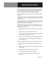
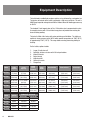
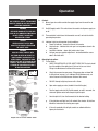
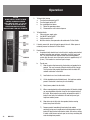
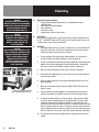
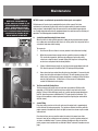
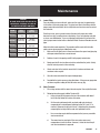
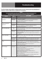
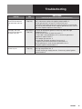
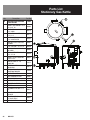
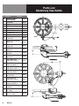
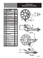
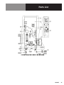
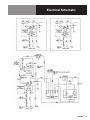
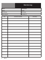
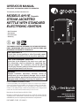
OPERATOR MANUAL IMPORTANT INFORMATION, KEEP FOR OPERATOR This manual provides information for: MODELS AH/1E Domestic STEAM JACKETED KETTLE WITH STANDARD ELECTRONIC IGNITION · Self-Contained · Gas Heated · Floor Mounted · Stationary THIS MANUAL MUST BE RETAINED FOR FUTURE REFERENCE. READ, UNDERSTAND AND FOLLOW THE INSTRUCTIONS AND WARNINGS CONTAINED IN THIS MANUAL. FOR YOUR SAFETY Do not store or use gasoline or other flammable vapors and liquids in the vicinity of this or any other appliance. POST IN A PROMINENT LOCATION Instructions to be followed in the event user smells gas. This information shall be obtained by consulting your local gas supplier. As a minimum, turn off the gas and call your gas company and your authorized service agent. Evacuate all personnel from the area. WARNING Improper installation, adjustment, alteration, service or maintenance can cause property damage, injury or death. Read the installation, operating and maintenance instructions thoroughly before installing or servicing this equipment. NOTIFY CARRIER OF DAMAGE AT ONCE It is the responsibility of the consignee to inspect the container upon receipt of same and to determine the possibility of any damage, including concealed damage. Unified Brands suggests that if you are suspicious of damage to make a notation on the delivery receipt. It will be the responsibility of the consignee to file a claim with the carrier. We recommend that you do so at once. Manufacture Service/Questions 888-994-7636. Information contained in this document is known to be current and accurate at the time of printing/creation. Unified Brands recommends referencing our product line websites, unifiedbrands.net, for the most updated product information and specifications. PART NUMBER 121051, REV. H (08/12) 1055 Mendell Davis Drive Jackson, MS 39272 888-994-7636, fax 888-864-7636 unifiedbrands.net IMPORTANT - READ FIRST - IMPORTANT WARNING: IMPROPER INSTALLATION, ADJUSTMENT, ALTERATION, SERVICE OR MAINTENANCE CAN CAUSE PROPERTY DAMAGE, INJURY OR DEATH. READ THE INSTALLATION, OPERATING AND MAINTENANCE INSTRUCTIONS THOROUGHLY BEFORE INSTALLING OR SERVICING THIS EQUIPMENT. WARNING: THE UNIT MUST BE INSTALLED BY PERSONNEL QUALIFIED TO WORK WITH GAS AND ELECTRICITY. WARNING: UNIT MUST BE INSTALLED IN ACCORDANCE WITH ALL APPLICABLE CODES. CAUTION: TO AVOID DAMAGING PARTS OF THE BURNER SYSTEM UNDERNEATH THE KETTLE, LIFT THE UNIT ONLY BY THE RING BENEATH THE OUTER PORTION OF THE BODY. WARNING: DO NOT ATTACH THE UNIT TO A TYPE “B” VENT. IT COULD CAUSE FIRE OR PROPERTY DAMAGE. WARNING: DO NOT CONNECT ANY PIPING TO THE SAFETY VALVE. IT MUST BE FREE TO VENT STEAM AS NEEDED. TO AVOID BURNS FROM THE VENTED STEAM THE VALVE DISCHARGE SHOULD POINT DOWN. IMPROPER INSTALLATION WILL VOID WARRANTY. WARNING: FAILURE TO PERIODICALLY CHECK SAFETY VALVE OPERATION COULD RESULT IN PERSONAL INJURY AND/OR DAMAGE TO EQUIPMENT. WARNING: WHEN TESTING, AVOID EXPOSURE TO THE STEAM BLOWING OUT OF THE SAFETY VALVE. DIRECT CONTACT COULD RESULT IN SEVERE BURNS. DANGER: ELECTRICALLY GROUND THE UNIT AT THE TERMINAL PROVIDED. FAILURE TO GROUND THE UNIT COULD RESULT IN ELECTROCUTION AND DEATH. CAUTION: BE SURE ALL OPERATORS READ, UNDERSTAND AND FOLLOW THE OPERATING INSTRUCTIONS, CAUTIONS AND SAFETY INSTRUCTIONS CONTAINED IN THIS MANUAL. CAUTION: DO NOT OVER FILL THE KETTLE WHEN COOKING, HOLDING OR CLEANING. KEEP LIQUIDS A MINIMUM OF 2-3” (5-8 CM) BELOW THE KETTLE BODY RIM TO ALLOW CLEARANCE FOR STIRRING, BOILING AND SAFE PRODUCT TRANSFER. CAUTION: KEEP FLOORS IN FRONT OF KETTLE WORK AREA CLEAN AND DRY. IF SPILLS OCCUR, CLEAN IMMEDIATELY TO AVOID SLIPS OR FALLS. WARNING: KEEP WATER AND SOLUTIONS OUT OF CONTROLS AND BURNERS. NEVER SPRAY OR HOSE DOWN THE CONTROL CONSOLE, ELECTRICAL CONNECTIONS, ETC. CAUTION: MOST CLEANERS ARE HARMFUL TO THE SKIN, EYES, MUCOUS MEMBRANES AND CLOTHING. TAKE PRECAUTIONS: WEAR RUBBER GLOVES, GOGGLES OR FACE SHIELD AND PROTECTIVE CLOTHING. CAREFULLY READ WARNINGS AND FOLLOW DIRECTIONS ON CLEANER LABELS. NOTICE: NEVER LEAVE A SANITIZER IN CONTACT WITH STAINLESS STEEL SURFACES LONGER THAN 10 MINUTES. LONGER CONTACT CAN CAUSE CORROSION AND PITTING. WARNING: TO AVOID INJURY, READ AND FOLLOW ALL PRECAUTIONS STATED ON THE LABEL OF THE WATER TREATMENT COMPOUND. WARNING: BEFORE REPLACING ANY PARTS, DISCONNECT THE UNIT FROM THE ELECTRIC POWER SUPPLY AND CLOSE THE MAIN GAS VALVE. ALLOW FIVE MINUTES FOR GAS TO VENT. CAUTION: 2 USE OF ANY REPLACEMENT PARTS OTHER THAN THOSE SUPPLIED BY AUTHORIZED DISTRIBUTORS CAN CAUSE OPERATOR INJURY AND DAMAGE TO THE EQUIPMENT, AND WILL VOID ALL WARRANTIES. OM-AH/1 IMPORTANT - READ FIRST - IMPORTANT WARNING: KEEP AREA AROUND KETTLE FREE AND CLEAR OF ALL COMBUSTIBLE MATERIALS. FAILURE TO DO SO COULD RESULT IN FIRE OR PROPERTY DAMAGE. CAUTION: HEATING AN EMPTY KETTLE MAY CAUSE THE RELEASE OF STEAM FROM THE SAFETY VALVE. CAUTION: UNIT WEIGHS 470 TO 1120 LB (212 TO 509 KG). FOR SAFE HANDLING, INSTALLER SHOULD OBTAIN HELP AS NEEDED, OR EMPLOY APPROPRIATE MATERIALS HANDLING EQUIPMENT (SUCH AS A FORKLIFT, DOLLY, OR PALLET JACK) TO REMOVE THE UNIT FROM THE SKID AND MOVE IT TO THE PLACE OF INSTALLATION. WARNING: THIS UNIT IS DESIGNED FOR COMMERCIAL USE. NEVER USE HOME OR RESIDENTIAL GRADE GAS CONNECTIONS. THEY DO NOT MEET COMMERCIAL GAS CODES AND COULD BE HAZARDOUS. IMPORTANT:SERVICE PERFORMED BY OTHER THAN FACTORY AUTHORIZED PERSONNEL WILL VOID WARRANTIES. OM-AH/1 3 Table of Contents Important Operator Warnings .....................................................page 2-3 References ................................................................................... page 4 Equipment Description ............................................................... page 5-6 Inspection and Unpacking ........................................................... page 7 Installation .................................................................................. page 8-9 Initial Start-Up .............................................................................. page 10 Operation ............................................................................... page 11-12 Sequence of Operation .............................................................. page 13 Cleaning .................................................................................. page 14-15 Maintenance ........................................................................... page 16-17 Troubleshooting ...................................................................... page 18-19 Parts List ................................................................................. page 20-26 Electrical Schematic .................................................................... page 27 Service Log ................................................................................. page 28 References CSA AMERICA INC 8501 East Pleasant Valley Road Cleveland, Ohio 44131 ANSI Z83.11 NSF INTERNATIONAL 798 N. Dixboro Rd. P.O. Box 130140 Ann Arbor, Michigan 48113-0140 NSF/ANSI 4 NATIONAL FIRE PROTECTION ASSOCIATION 60 Battery March Park Quincy, Massachusetts 02269 NFPA/70 The National Electrical Code NFPA/54 Installation Gas Appliances & Piping AMERICAN NATIONAL STANDARDS INST., INC 1430 Broadway New York, New York 10018 Z223.1-1984 National Fuel Gas Code Z21.30 Installation of Gas Appliances & Piping 4 OM-AH/1 Equipment Description AH/1 steam kettles are stainless steel, floor mounted kettles with a self-contained steam source heated by gas. A closed steam jacket covers the lower portion of the kettle. Heat from the gas burner boils water in the jacket to produce steam under pressure. To ignite the burners, the kettle uses electronic spark ignition. The kettles are stationary (non-tilting). Liquids can be removed through the tangent draw-off valve. Exposed surfaces are stainless steel. Insulated sheathing protects the kettle body, and a housing encloses the controls. Three tubular legs support the unit. Bullet feet adjust to level the kettle. A one piece dome cover is hinged to the kettle on the 20-gallon model. Covers for 40, 60, 80, and 100-gallon kettles are supplied with counterbalancing spring actuators to hold the covers in the fully open or closed position. Controls provided include the ON/OFF switch, to control electric power for the unit, and the thermostat, to set the cooking temperature. The automatic controls and a brief description of each are as follows. 1. Gas pressure regulator: Protects the unit from high pressure in the gas supply line. 2. Automatic gas valves: Allow gas into the burners as needed. 3. Pressure limit switch: Turns off the burner when jacket pressure reaches 27 PSI. Lights the burner when pressure drops to 22 PSI. 4. Safety valve: Lets steam out of the jacket if the steam pressure exceeds 30 PSI. 5. Low-water cutoff: Turns off the burner if the water level in the jacket gets too low for safe operation. Instruments also are provided to show what is happening inside the unit. These are: 1. Water level sight glass: Indicates whether there is enough water in the steam jacket. 2. Pressure/vacuum gauge: Shows steam pressure, and whether too much air has entered the jacket. 3. Heating indicator light: Indicates that the kettle is being heated. 4. Power on indicator light: Glows when the unit is turned on. 5. Low water indicator light: Lights to show that jacket water needs to be replenished. OM-AH/1 5 Equipment Description The kettle body is welded into one piece and has a rim reinforced by a rectangular bar. The interior and exterior of the kettle is polished to a 180 emery grit finish. The unit is ASME shop inspected and registered with the National Board for working pressures up to 30 PSI. The standard 2 inch tangent draw-off is a 316 stainless steel, compression disc valve. A removable strainer with 1/4 inch holes keeps pieces of product from entering the draw-off during cooking. The jacket is filled at the factory with water containing rust inhibitors. The kettle can operate at steam pressures up to 30 PSI, which provide temperatures of 150°F (65°C) to approximately 270°F (135°C). This range allows warming, simmering, boiling, or braising. For the kettles, options include: 1. 2. 3. 4. 5. 6. 7. Larger (3 inch) draw-off Solid disc strainer or strainer with 1/8 inch perforations Water fill faucets Basket inserts Kettle brush kit Gallon etch marks Flanged feet Model Kettle Capacity Jacket Capacity Kettle Inside Diameter Kettle Depth Overall Width Front-to-Back Rim Height AH/1E-20 20 Gallon (75 liter) 4-1/2 Gallon (17 liter) 20 inches (508 mm) 18 inches (457 mm) 36-3/4 inches (934 mm) 39 inches (991 mm) 40 inches (1016 mm) AH/1E-40 40 Gallon (150 liter) 7 Gallon (26.5 liter) 26 inches (660 mm) 22 inches (559 mm) 38-1/4 inches (972 mm) 45 inches (1143 mm) 42 inches (1067 mm) AH/1E-60 60 Gallon (225 liter) 9-1.2 Gallon (36 liter) 30 inches (762 mm) 25 inches (635 mm) 41 inches (1041 mm) 49 inches (1245 mm) 49 inches (1245 mm) AH/1E-80 80 Gallon (300 liter) 11-1/2 Gallon (43.5 liter) 32 inches (813 mm) 29 inches (737 mm) 42-1/2 inches (1080 mm) 51 inches (1295 mm) 55-1/2 inches (1410 mm) AH/1E-100 100 Gallon 11-1/2 Gallon (375 liter) (43.5 liter) 32 inches (813 mm) 35 inches (889 mm) 42-1/2 inches (1080 mm) 51 inches (1295 mm) 61-1/2 inches (1562 mm) Model Ignition AH/1E-20 FIRING RATE, BTU/HOUR Natural Gas Propane Gas Spark 85,000 85,000 AH/1E-40 Spark 100,000 85,000 AH/1E-60 Spark 145,000 145,000 AH/1E-80 Spark 145,000 145,000 AH/1E-100 Spark 145,000 145,000 6 OM-AH/1 Inspection & Unpacking WARNING INSTALLATION OF THE KETTLE MUST BE DONE BY A CERTIFIED ELECTRICIAN OR AUTHORIZED REPRESENTATIVE QUALIFIED TO WORK WITH ELECTRICITY. IMPROPER INSTALLATION CAN RESULT IN INJURY TO PERSONNEL AND/OR DAMAGE TO EQUIPMENT. CAUTION SHIPPING STRAPS ARE UNDER TENSION AND CAN SNAP BACK WHEN CUT. TAKE CARE TO AVOID PERSONAL INJURY OR DAMAGE TO THE UNIT BY STAPLES LEFT IN THE WALLS OF THE CARTON. CAUTION UNIT WEIGHS FROM 468 LBS (212 KG) TO 1120 LBS (508 KG). FOR SAFE HANDLING, INSTALLER SHOULD OBTAIN HELP AS NEEDED AND USE MATERIAL HANDLING EQUIPMENT TO REMOVE THE UNIT FROM THE SKID AND MOVE IT TO ITS PLACE OF INSTALLATION. The unit arrives completely assembled, except for the TDO valve and flue gas converter, which are usually packed separately and shipped inside the kettle.. The unit is strapped on a skid in a heavy box. Inspect the box carefully for damage. Open the container and check the unit for hidden damage. Report shipping damage or shipment errors to the delivery agent. Write down the model number, serial number, and installation date for your unit at the top of the Maintenance and Service Log at the back of this manual. Keep the manual with the unit. To remove the kettle from the box, cut any straps from around the box. Detach the box sides from the skid. Pull the box up off the unit, taking care to avoid damage or injury from any staples left in the box walls. When installation is to begin, cut the straps holding the kettle to the skid, and lift the kettle straight up off the skid. Examine the packing materials to make sure no loose parts are discarded with the materials. Once the kettle is unpacked, the tangent draw-off valve is easily attached, as shown below. The large nut which attaches the valve to the kettle should be hand tightened only. Assemble and attach the tangent draw-off valve after the kettle is unpacked. OM-AH/1 7 Installation WARNING THIS PRODUCT MUST BE INSTALLED BY A LICENSED PLUMBER OR GAS FITTER WHEN INSTALLED WITHIN THE COMMON WEALTH OF MASSACHUSETTS. IMPROPER INSTALLATION CAN CAUSE INJURY TO PERSONNEL AND/OR DAMAGE TO THE EQUIPMENT. THIS UNIT IS FOR COMMERCIAL USE. NEVER USE HOME OR RESIDENTIAL GRADE GAS CONNECTIONS. THEY DO NOT MEET GAS CODES AND COULD BE HAZARDOUS. NOTICE TO AVOID DAMAGING PARTS OF THE BURNER SYSTEM UNDERNEATH THE KETTLE, LIFT THE UNIT ONLY BY THE RING BENEATH THE OUTER PORTION OF THE BODY. CAUTION DO NOT CONNECT ANY PIPING TO THE PRESSURE RELIEF SAFETY VALVE. IT MUST BE FREE TO VENT STEAM AS NEEDED. ELBOW SHOULD POINT DOWN TOWARD FLOOR. IMPROPER INSTALLATION WILL VOID WARRANTY! DANGER ELECTRICALLY GROUND THE UNIT AT THE TERMINAL PROVIDED. FAILURE TO GROUND UNIT COULD RESULT IN ELECTROCUTION AND DEATH. The unit should be installed in a ventilated room for efficient performance. Items which may obstruct or restrict the flow of air for combustion and ventilation must be removed. The area directly around the appliance must be cleared of all combustible materials. 1. Installation requires connection with gas and electrical services. See items 8 to 14 for details. 2. To protect the unit from damage, leave it on the shipping pallet until the time of installation. When installation is to begin, cut the straps holding the kettle, and hoist the kettle straight up off the skid. 3. Install the unit with a minimum clearance to combustible and non-combustible construction of six inches at the sides and six inches between the draft diverter and the wall. Also leave enough room for cleaning, maintenance, and service. 4. The draft diverter shipped with the kettle is the correct height and shape to give maximum performance. Install the draft diverter as shown on the figures at left. Securely fasten the screw to attach draft directly. Do not change the diverter in any way. Install the unit under a ventilation hood, or vent the flue directly to a masonry chimney. Put a hood at least several inches above the upper end of the draft diverter. Do not rest hood supports on the diverter. Installation of a ventilating hood should comply with local codes and/or ANSI/NFPA-96 Latest Edition. Also, local codes may require that the kettle be electrically interlocked to shut off the gas supply and prevent the operation of the unit if the exhaust fan is not operating or if the fire suppression system is activated. Failure to follow these instructions can cause bodily injury and/or property damage. 5. To level the unit, adjust leg length by turning the bullet feet. 6. Make sure the water level is correct in the jacket, by confirming that the level is between the marks on the gauge glass. If the water level is low, follow the instructions under “Jacket Filling” in the “Maintenance” Section of this manual. 7. To protect personnel from steam coming out of the safety valve, the open end of the elbow at the outlet must be directed down. If it is not, turn the elbow to the correct position. 8. Provide 115 VAC, 60 HZ, 1 PH, 15 AMP electrical service for standard unit. Unit may be equipped for alternate electrical service of 208 VAC or 240 VAC, as ordered. Use 1/2 inch waterproof conduit and waterproof connections. Observe local codes and/or The National Electrical Code in accordance with ANSI/NFPA 70 - latest edition. AN ELECTRICAL GROUND IS REQUIRED. The electrical schematic is located on the inside of the service panel. In Canada, provide electrical service in accordance with the Canadian Electrical Code, CSA C22.1 Part 1 and/or local codes. 9. The internal gas lines of the unit were cleaned and closed off with a gas cock before the unit was shipped from the factory. Free all external gas lines of lint, dirt, metal chips, sealant, grease, oil, and other contaminants, before you connect the lines to the kettle. 10. Connect the gas cock of the kettle to the gas service main with 3/4 inch IPS line or approved equivalent. 8 OM-AH/1 Installation 11. Installation must conform with local codes, or in the absence of local codes, with the National Fuel Gas Code, ANSI Z 223.1-1988 (or latest edition). The unit should be installed in an adequately ventilated room with a provision for adequate air supply. The best ventilation will utilize a vent hood and exhaust fan with no direct connection between the vent duct and the flue. Do NOT obstruct the flue or vent duct after installation. In Canada, the installation must conform to the CAN/CGA B149 Installation Codes for Gas Burning Appliances and Equipment and/or local codes. 12. Adequate space for proper service and operation is required. No NOT block any air intake spacings to the combustion chamber or obstruct the air flow by piling or stacking anything near the kettle. 13. After the kettle has been connected to the gas supply, all gas line joints must be checked for leaks. DO NOT USE A FLAME TO CHECK FOR LEAKS. A thick soap solution or other suitable leak detector should be employed. 14. For a unit on casters, complete connection to the gas supply with connectors that comply with the standard for connectors for moveable gas appliances, ANSI Z21.69 - latest edition. Restrain movement of the unit by attaching a cable or chain to the eyelet (provided at the back of the frame) and anchoring the cable or chain to the wall or floor. Make the length and location of the cable such that the unit cannot pull on the gas connection while the cable is connected. 15. The appliance and its individual shutoff valve must be disconnected from the gas supply piping system during any pressure testing of that system at test pressures in excess of 1/2 PSIG (3.48 kPa). The appliance must be isolated from the gas supply piping system by closing its individual manual shutoff valve during any pressure testing of the gas supply piping system at test pressures equal to or less than 1/2 PSIG (3.48 kPa). 16. Check the following points to confirm that your kettle has been installed properly. Any mechanical, electrical, or gas type change must be approved by the Food Service Engineering Department. a. Enough room between the kettle and nearby objects for cleaning and service. b. Minimum clearance of 6 inches from sides and 6 inches from draft diverter. c. Unit vented to a hood or chimney (not attached to a vent). d. Kettle level. e. Correct amount of water in the jacket. f. Pressure relief safety valve outlet pointed down. g. Connected with a waterproof, 115 volt, 15 AMP supply of electric power in accordance with electrical codes. h. Gas lines cleaned before connection. i. Gas connected with 3/4 inch pipe or equivalent. j. Gas line joints checked for leaks. k. No obstruction to air supply or venting. OM-AH/1 9 Initial Start-Up IMPORTANT BE SURE ALL OPERATORS READ, UNDERSTAND AND FOLLOW THE OPERATING INSTRUCTIONS, CAUTIONS AND SAFETY INSTRUCTIONS CONTAINED IN THIS MANUAL. WARNING AVOID ALL DIRECT CONTACT WITH HOT SURFACES. DIRECT SKIN CONTACT COULD RESULT IN SEVERE BURNS. AVOID ALL DIRECT CONTACT WITH HOT FOOD OR WATER IN THE KETTLE. DIRECT CONTACT COULD RESULT IN SEVERE BURNS. After kettle has been installed, the installer should test to ensure that it is operating correctly. . DIRECT SKIN CONTACT 1. Remove all literature and packing materials from inside and outside of the unit. 2. Install the TDO valve. 3. Put a small amount of water into the kettle. 4. Verify that kettle water level is normal and that kettle is holding vacuum in jacket. Correct if not. 5. Make sure the supplies of gas and electric power are on. 6. Follow the “Start Kettle Heating” instructions in the Operation section of this manual. Begin heating the water at the highest thermostat setting. The indicator light should come on and heating should continue until the water boils. 7. To turn off the unit, follow “To Stop Kettle Heating” in the Operation section. If the kettle functions as described, if is read for use. If the unit does not operate as designed, contact authorized Service Agent. 10 OM-AH/1 Operation WARNING ANY POTENTIAL USER OF THE EQUIPMENT MUST BE TRAINED IN SAFE AND CORRECT OPERATING PROCEDURES. A. 2. On-Off (toggle) switch. This switch turns the control circuit power supply on or off. WARNING KEEP AREA AROUND KETTLE FREE AND CLEAR OF ALL COMBUSTIBLE MATERIALS. DO NOT ATTEMPT TO LIGHT ANY BURNER WITH A FLAME. 3. Thermostat dial, which turns the thermostat on or off, and sets the kettle operating temperature. CAUTION HEATING AN EMPTY KETTLE MAY CAUSE THE RELEASE OF STEAM FROM THE SAFETY VALVE. WARNING AVOID ALL DIRECT CONTACT WITH HOT FOOD OR WATER IN THE KETTLE. DIRECT CONTACT COULD RESULT IN SEVERE BURNS. TAKE CARE TO AVOID CONTACT WITH HOT KETTLE BODY OR HOT PRODUCT. WHEN ADDING INGREDIENTS, STIRRING OR TRANSFERRING PRODUCT TO ANOTHER CONTAINER. Controls 1. Manual gas valve which controls the supply of gas from the main line to the unit. 4. Indicator Lights to alert operator of unit conditions: a. Power On Indicator - shows that the unit is turned on b. Heat Indicator - indicates that main gas is on to produce steam in the kettle jacket. c. Low Water indicator - shows that jacket water is low d. Unit gas pressure regulator adjustment - located behind the access door in the kettle skirt. B. Operating Instructions 1. To Start Kettle a. CHECK THE WATER LEVEL IN THE JACKET EVERY DAY. The level should be at the middle of the sight glass. If the level is low, see Jacket Filling in the Maintenance section of this manual b. Check the pressure/vacuum gauge. If the gauge does not show 20 to 30 inches of vacuum (i.e. a reading of 20 to 30 below zero), see Jacket Vacuum in the Maintenance section of this manual. c. DO NOT attempt to light any burner with a flame. d. Open main supply gas valve (handle in line with the pipe). e. Turn the toggle switch to ON. For 90 seconds, or until it succeeds, the electronic ignition control will attempt to light the pilot. f. Once the pilot is lit, turn the thermostat to the desired setting. g. If the pilot does not light, turn it off and wait five minutes. At that time follow the instructions for starting once again. h. If the unit repeatedly fails to light, contact an authorized Service Agency for assistance. Hinged cover for smaller models shown. OM-AH/1 11 Operation CAUTION DO NOT OVERFILL THE KETTLE WHEN COOKING, HOLDING OR CLEANING. KEEP LIQUIDS AT LEAST 2-3” (5-8 cm) BELOW THE KETTLE BODY RIM TO ALLOW CLEARANCE FOR STIRRING, BOILING PRODUCT AND SAFE TRANSFER. 2. To Stop Kettle Heating a. Turn the thermostat dial to OFF. b. Turn the toggle switch OFF. c. For a prolonged shut-down: 1) Follow the procedure above. 2) Disconnect the unit’s electrical power. 3. To Relight Kettle a. Close main gas supply valve. b. Set ON/OFF switch to OFF. c. Set thermostat to OFF. d. Wait five minutes, then proceed as directed under To Start Kettle. 4. If electric power fails, do not attempt to operate the unit. When power is restored, proceed as directed in To Start Kettle. 5. Basket Insert a. An optional kettle basket insert set will assist in cooking water-boiled products including eggs, potatoes, vegetables, shell fish, pasta and rice. The nylon mesh liners must be used when cooking product smaller than the mesh size of the basket, which is approximately 1/4” (6 mm). This incudes rice and small pasta shapes. b. Tips for use: 1) Allow for water displacement by the baskets and product to be cooked. This may mean only filling the kettle half full of water. Test the basket and product displacement with the kettle OFF, and with cold water in the kettle. 2) Load baskets on a level, stable work surface. 3) Lift the loaded baskets with both hands. Get help from another person if the basket is too heavy for safe handling. 4) Slowly lower product into the kettle. 5) When removing baskets with cooked product, lift basket straight up, ensuring bottom of basket clears the rim and pouring lip of the kettle. Wear protective oven mitts and protective apron. If basket is too heavy for individual to lift and safely move, get help from another person. 6) Allow hot water to fully drain from product, before moving basket away from the kettle. 7) Remove product immediately from basket into another container, being sure to avoid contact with hot product and hot basket OR place basket with food on stable, flat surface, setting it inside a solid steamer or bake pan, to catch any remaining hot water draining from product. 12 OM-AH/1 Sequence of Operation The following “action-reaction” outline is provided to help understand how the kettle works. 1. When the power switch is turned on, it starts the spark igniter and opens the automatic valve for the pilot burner. The spark ignites a pilot flame, which heats the sensor. The sensor then sends a signal to turn off the spark. The flame thereafter acts as a standing pilot until the power is turned off. 2. If the pilot flame is not sensed within 90 seconds after spark begins, a timer shuts down the entire operation. To attempt a second trial for ignition, turn off the power switch. Check the gas supply valves and wait five minutes before trying again by switching power on. If you cannot establish a pilot flame in four tries, close all valves, turn off the power, and contact an authorized Service Agency. 3. When the operator sets a temperature on the thermostat, it causes the automatic valve to admit gas to the main burner, where it is ignited by the pilot flame. When the kettle reaches the set temperature, the thermostat switch opens. This stops the signal to the gas control valve and shuts off gas to the main burner. The pilot flame stays lit. 4. When the kettle cools below the set temperature, the thermostat switch closes and start another cycle. On and off cycling continues and maintains the kettle at the desired temperature. This action is indicated by the Heat Indicator light. The kettle has the following safety features in addition to the 90-second ignition timer: 1. Low water cutoff relay that will shut off gas supplies to all burners until the jacket water level is corrected. 2. High limit pressure switch, set to open at about 26 PSI and to shut down the burners until jacket pressure is decreased. 3. Pressure relief safety valve, which will release steam if jacket pressure exceeds 30 PSI. 4. Gas pressure regulator built into the gas control valve. OM-AH/1 13 Cleaning WARNING KEEP WATER AND SOLUTIONS OUT OF CONTROLS AND ELECTRICAL EQUIPMENT. DO NOT USE A HIGH PRESSURE HOSE TO CLEAN THE CONTROL CONSOLE, ELECTRICAL CONNECTIONS, ETC. CAUTION NEVER LEAVE A CHLORINE SANITIZER IN CONTACT WITH STAINLESS STEEL SURFACES FOR LONGER THAN 30 MINUTES. LONGER CONTACT CAN CAUSE CORROSION. CAUTION MOST CLEANERS ARE HARMFUL TO THE SKIN, EYES, MUCOUS MEMBRANES AND CLOTHING. PRECAUTIONS SHOULD BE TAKEN TO WEAR RUBBER GLOVES, GOGGLES OR FACE SHIELD AND PROTECTIVE CLOTHING. CAREFULLY READ THE WARNINGS AND FOLLOW LABEL DIRECTIONS. When attaching the draw-off valve, just hand-tighten the nut. A. Suggested Cleaning Supplies 1. A high quality detergent and sanitizer, or a combination cleaning sanitizing agent. 2. Kettle brushes in good condition. 3. Spray Degreaser. 4. De-limer/De-scaler. 5. A high quality stainless steel cleaner. B. Precautions Before any cleaning operation, shut off the kettle by turning the thermostat dial to “OFF”, the ON/OFF switch to OFF, and shut off all electric power to the unit at a remote switch, such as the circuit breaker. C. Procedure 1. Clean food contact surfaces as soon as possible after use, preferably while the kettle is still warm. If the unit is in continuous use, clean and sanitize inside and outside at least once every 24 hours. 2. Scrape and flush out large amounts of food residues. Be careful not to scratch the kettle with metal implements. Close the draw-off. 3. Prepare a solution of the detergent/cleaning compound as instructed by the supplier. Clean the unit thoroughly. A cloth moistened with cleaning solution can be used to clean controls, housing, electrical conduit, etc. 4. Rinse the kettle thoroughly with hot water. Then drain completely. 5. Disassemble the tangent draw-off valve. Clean the draw-off port and each valve part with a brush. 6. Rinse the kettle and draw-off valve parts thoroughly with hot water, then drain completely. 7. When you reassemble the draw-off valve, HAND-TIGHTEN the nut which holds it in place. 8. As part of the daily cleaning program, clean soiled external and internal surfaces. Remember to check the sides of the unit and control housing. 9. To remove burned-on foods, use a brush, sponge, cloth, plastic or rubber scraper, or plastic wool along with the cleaning solution. To reduce effort required in washing, let the detergent solution sit in the kettle for a few minutes and soak into the residue. Do NOT use abrasive materials or metal tools that might scratch the surface. Scratches make the surface harder to clean and provide places for bacteria to grow. Do not use steel wool, which will leave particles in the surface and cause eventual corrosion and pitting. 10. The outside of the unit may be polished with a recognized stainless steel cleaner. 14 OM-AH/1 Cleaning CAUTION NEVER LEAVE A CHLORINE SANITIZER IN CONTACT WITH STAINLESS STEEL SURFACES FOR LONGER THAN 30 MINUTES. LONGER CONTACT CAN CAUSE CORROSION. 11. When the equipment needs to be sanitized, use a sanitizing solution equivalent to one that supplies 200 parts per million chlorine. Obtain advice on the best sanitizing agent from your supplier of sanitizing products. Following the suppliers instructions, apply the sanitizing agent after the unit has been cleaned and drained. Rinse off the sanitizer thoroughly. 12. It is recommended that each piece of equipment be sanitized just before use. Use a brush, sponge, cloth, plastic or rubber scraper, or plastic wool to clean. 13. If there is difficulty removing mineral deposits or a film left by hard water or food residues, clean the kettle thoroughly and then use a deliming agent, in accordance with the manufacturer’s directions. Rinse and drain the unit before further use. 14. If cleaning problems persist, contact your cleaning product supplier for assistance. The supplier has a trained technical staff with laboratory facilities to serve you. Don’t use metal implements or steel wool when cleaning. OM-AH/1 15 Maintenance WARNING WHEN USING THE EQUIPMENT OR TESTING, AVOID ANY EXPOSURE TO THE STEAM BLOWING OUT OF THE SAFETY VALVE. SEVERE BURNS CAN RESULT ON EXPOSED SKIN. FAILURE TO CHECK SAFETY VALVE OPERATION PERIODICALLY COULD RESULT IN PERSONAL INJURY AND/OR DAMAGE TO EQUIPMENT. NOTICE: Contact an authorized representative when repairs are required. A Maintenance & Service Log is provided at the back of this manual. Each time maintenance is performed on your kettle, enter the date on which the work was done, what was done, and who did it. Keep this manual on file and available for operators to use. Periodic inspection will minimize equipment down time and increase the efficiency of operation. The following points should be checked: A. Jacket Vacuum/Removing Air from Jacket When the kettle is cold, a positive pressure reading on the pressure/vacuum gauge or a reading near zero indicates that there is air in the jacket. Air in the jacket acts as an insulator, and slows kettle heating. To remove air: 1. Start the unit. (Be sure there is water or product in the kettle when heating). 16 OM-AH/1 2. When the pressure/vacuum gauge reaches a positive pressure reading of 5 PSI, release the trapped air and steam by pulling up or out on the safety valve lever or ring for about 1 second. Repeat this step, then let the pull ring or valve lever snap back into the closed position. 3. If there is little discharge (mostly air), and the pressure gauge drops back to 0 PSI, allow the pressure to build back to 5 PSI and repeat the procedure. 4. Once steam has been vented from the jacket as described in 2, remove the hot water from the kettle and replace it with cold. This will condense steam in the kettle jacket, and the pressure gauge should show a reading of 20 to 30 inches mercury (Hg) below zero. If it does not, or if the vacuum is leaking down, contact an authorized service agency. B. Test Pressure Relief Safety Valve Test the pressure relief safety valve at least twice each month. With the kettle operating at 5 PSI (105 kPa), pull the test lever and let it snap back to its closed position. If there is little discharge (mostly air), and the pressure gauge drops back to 0 PSI, allow the pressure to build back to 5 PSI and repeat the procedure. (Tip: Using a will screwdriver or other implement to pull the ring help you avoid contact with the steam.) C. Jacket Filling Every day, before you turn on the unit, make sure the water level is approximately in the center of the water gauge glass. The jacket was filled at the factory with the proper amount of treated water, and is air-tight, but over time steam may be vented and water lost. From time to time, you may need to restore the water to its proper lever either because it was lost as venting steam or by draining. If you are replacing water lost as steam, use distilled water. If you are replacing treated water that ran out of the jacket, prepare more treated water as directed in Water Treatment Procedure on next page. Maintenance WARNING TO AVOID INJURY, READ AND FOLLOW ALL PRECAUTIONS STATED ON THE LABEL OF THE WATER TREATMENT COMPOUND. Model Kettle Capacity Jacket Capacity AH/1E-20 20 Gallon (75 liter) 4-1/2 Gallon (17 liter) AH/1E-40 40 Gallon (150 liter) 7 Gallon (26.5 liter) AH/1E-60 60 Gallon (225 liter) 9-1.2 Gallon (36 liter) AH/1E-80 80 Gallon (300 liter) 11-1/2 Gallon (43.5 liter) AH/1E-100 100 Gallon 11-1/2 Gallon (375 liter) (43.5 liter) C. Jacket Filling Every day, before you turn on the unit, make sure the water level is approximately in the center of the water gauge glass. The jacket was filled at the factory with the proper amount of treated water, and is air-tight, but over time steam may be vented and water lost. From time to time, you may need to restore the water to its proper lever either because it was lost as venting steam or by draining. If you are replacing water lost as steam, use distilled water. If you are replacing treated water that ran out of the jacket, prepare more treated water as directed in Water Treatment Procedure on next page. Allow the kettle to cool completely. The procedure will be easier with the kettle under vacuum (pressure gauge reading below zero). 1. Make sure the fill (gate) valve is closed, and remove the square head pipe plug with open-ended wrench or crescent wrench. D. 2. Position a funnel in the opening and fill it with properly treated water. 3. Slowly open the fill valve to allow water to be sucked into the jacket. Quickly close the valve to prevent air from entering. 4. Check water level in the jacket to ensure that it is between minimum and maximum marks on glass. 5. Close the valve and reinstall the square-head pipe plug. 6. Reestablish the jacket vacuum as described above. If the pressure gauge does not show a negative reading of 20 to 30 inches mercury (Hg). Water Treatment 1. Fill a mixing container with the amount of water required. Use only distilled water. 2. Following instructions apply to Water Treatment Kit. a. Hang a strip of pH test paper on the rim of the container, with about 1 inch of the strip below the surface of the water. b. Stir the water continuously while you slowly add water treatment compound until a color between indicating a pH of 10.5 and 11.5 is reached. (Shown on the pH test kit chart.) Judge the pH by frequently comparing the test strip with the color chart provided in the kit. c. Use a measuring cup to add the compound so that you may record the exact amount used. d. The amount may be used again if the same water sources and compound are used in the future. However, it is best to check the pH each time treated water is prepared. OM-AH/1 17 Troubleshooting Your kettle is designed to operate smoothly and efficiently if properly maintained. However, the following is a list of checks to make in the event of a problem. Wiring diagrams are furnished inside the service panel and in this manual. If an item on the list is followed by x, the work should be done by a qualified service representative. WARNING USE OF ANY REPLACEMENT PARTS OTHER THAN THOSE SUPPLIED BY AN AUTHORIZED SUPPLIER/DISTRIBUTOR WILL VOID ALL WARRANTIES AND COULD INJURE THE OPERATOR OR DAMAGE THE EQUIPMENT. SYMPTOM WHO Kettle continues heating after it reaches the desired temperature. User Kettle stops heating before it reaches the desired temperature. Safety valve pops open. Auth Service Rep Only User Auth Service Rep Only User Auth Service Rep Only Burners will not light. User WHAT TO CHECK X indicates items which must be performed by an authorized technician. a. Thermostat dial setting. b. Thermostat calibration. c. Thermostat operation. The thermostat should click when the dial is rotated above and below the setting for the temperature of the kettle. X a. Thermostat dial setting. b. Thermostat calibration. X c. Thermostat operation. Thermostat should click when the dial is rotated above and below the setting for the temperature of the kettle. X a. For air in the jacket. See “Jacket Vacuum” in the Maintenance section. b. Thermostat dial setting. c. For defective thermostat. The thermostat should click when the dial is rotated to settings above and below the temperature of the kettle. If defective, replace. X d. For defective safety valve. If the valve pops at pressures below 29 PSI, replace. X a. That the main gas supply valve is open. (handle is in line with the gas pipe). b. Gas supply to the building. Auth Service Rep Only c. Thermostat operation. The thermostat should click when the dial is rotated to settings above and below the temperature of the kettle. X System does not produce a spark. Auth Service Rep Only a. AC voltage between terminals on secondary side of transformer with unit power turned on. If it is not 24 Volt, replace the transformer. X b. That the high tension cable is firmly attached and in good condition. If cracked or brittle, replace. X c. Pilot burner ceramic insulator for crack or break. X d. Pilot spark gap. Regap. X Spark is present but the pilot will not light. Auth Service Rep Only a. That the pilot valve is securely connected to terminals. X b. For 24 VAC at terminals PV and PV/MV. If 24V is not present, replace the ignition control module. X b. That gas pressure is at least 3.5” W.C.(8.7818 b). c. For gas at the pilot. If it is not flowing: (1) Check the pilot gas line for kinks and obstructions. X (2) Clean orifice, if necessary. X (3) Check magnetic operator for pilot valve on gas valve. Repair or replace as necessary. X d. That the pilot spark gap is located in the pilot gas stream. If not, adjust or replace the pilot burner. X e. For drafts. Shield the pilot burner, if necessary. X 18 OM-AH/1 Troubleshooting SYMPTOM WHO WHAT TO CHECK X indicates items which must be performed by an authorized technician. Pilot lights, but main burner will not come on and spark does not stay on. Auth Service Rep Only a. For 24 V between terminals MV and PV/MV while pilot is burning. If 24V is not present, replace the ignition control module. X b. That gas pressure is at least 3.5” W.C.(8.7818 b). X c. Electrical connections of the main valve to terminals, to assure that they are securely attached. Check magnetic operator for main valve on gas valve. Repair or replace as necessary. X Pilot lights, but main burner will not come on, the spark stays on. Auth Service Rep Only a. Check for bad burner ground. If necessary, repair with high temperature wire. X b. Pilot burner ceramic insulator for cracks. X c. That cable is not grounded out. If it is, correct the ground-out condition or replace cable. X d. For proper gas pressure. X e. Clean pilot assembly, or replace if necessary. X f. Tighten all mechanical and electrical connections. X g. If the pilot flame is weak, increase pilot orifice size. X h. Replace ignition control module. X Main burner comes on but will not stay on. Auth Service Rep Only a. Check burner ground for bad wire or connection. Replace if necessary with high temperature wire. X b. Check for low gas supply pressure. If necessary, replace ignition control module. X OM-AH/1 19 Parts List Stationary Gas Kettle Key Description Part No. HARDWARE ASM 40-GALLON SPARK IGNITION 117095 BRACKET, GAS MANIFOLD 1/8 X 1 X 15-3/4” LG 002006 NAMEPLATE CLASS II 1” X 4-1/2” LONG 003479 HINGE, SPRING LOADED 18 GA X 1 X 1-1/4” 004114 CLAMP BAR PIPE 1/4” X 1 X 4-1/2” LG WITH STUD 004568 DOOR INSULATED PILOT LIGHT ASSEMBLY 008201 PLATE, CAUTION 1-3/8 X 2-1/4” 008350 CHAIN SINGLE, JACK LINK #16 600” LONG 009009 SCREW, SHEET METAL PAN HD #12 X 1/2” LG 008769 BRACKET, FAUCET MOUNTING 16 GA X 4-3/4” 009054 DIVERTER, DRAFT 6”, 20, 40-GALLON 012474 DIVERTER, DRAFT 7”, 60, 80, 100-GALLON 000576 NUT HEX KEPS 1/4”-20 W/ SHAKEPROOF WASHER 012940 NAMEPLATE, LARGE 055450 LABEL, WARRANTIES VOID 059201 LABEL, WARNING 093614 B COVER POWER AID ASSEMBLY 047693 C POT INNER ASSEMBLY - D TDO KIT - A 20 NUT, WING #10-24 FOR 1-1/2” & 2” 009028 HANDLE, 3” DIA SANITARY & TDO VALVE 127452 STRAINER ASSEMBLY 9” DIA, 1/4” HOLES FOR 2” 009044 HANDLE, SANITARY 170061 OM-AH/1 Parts List Stationary Gas Kettle Key Description Part No. SAFETY VALVE AND WATER FILL ASSEMBLY 097010 SAFETY VALVE 30 PSI 1/2” NPT 156047 ELBOW 90 DEG STREET 1/2” NPT BLACK 096905 PLUG PIPE 1/2” NPT 011146 ELBOW 90 DEG STREET 1/2” NPT 004185 TEE, 1/2” NPT 008772 VALVE SWING CHECK 1/2” NPT 004187 NIPPLE, 1/2” NPT X CLOSE 008877 VALVE, GATE 1/2” NPT 004180 LABEL, WARNING 098171 WIRING DIAGRAM LABEL 123863 HARNESS WIRING 123864 NUT HEX 3/8”-16 005619 WASHER, LOCK #10 005619 WASHER, LOCK 3/8” 005618 E SHELL OUTER/INNER ASSEMBLY 127445 F BURNER AND SENSOR ASSEMBLY - G GAS VALVE, PIPE & ELEC ASSEMBLY 127335 IGNITION MODULE BOX ASSEMBLY 127334 ELECTRICAL PANEL ASSEMBLY 123823 OM-AH/1 21 Parts List Stationary Gas Kettle Key Description Part No. F BURNER ASSEMBLY 20 & 40-GALLON 127331 1 BURNER HEAD 000286 2 90º ELBOW, 2-1/2” NPT 000289 3 VENTURI 000287 4 AIR SHUTTER 000288 5 SPUD ORIFICE 000279 6 RETAINING RING, E TYPE 000460 7 LOCK NUT, 3/8” NPT 000294 8 ORIFICE, N.G., 20-GALLON, 0’-1500’ ELEV 000489 8 ORIFICE, PROP, 20-GALLON, HIGHER ELEV 000281 8 ORIFICE, N.G., 40-GALLON, 0’-1500’ ELEV 000280 8 ORIFICE, PROP, 40-GALLON, HIGHER ELEV 000281 9 BRACKET, PILOT BURNER MOUNTING 123824 10 SCREW #10-24 X 3/8” LG. ROUND HEAD 006009 11 PILOT BURNER ASSY 20-GALLON, 0’-1500’ EL 096705 11 PILOT BURNER ASSY 20-GALLON, HIGHER EL 096706 11 PILOT BURNER ASSY 40-GALLON, 0’-1500’ EL 096705 11 PILOT BURNER ASSY 40-GALLON, HIGHER EL 096706 12 SCREW #10-32 X 1/4 FILLISTER HEAD 090797 13 PILOT ORIFICE SPUD 40-GALLON, 0-1500’ EL 098647 13 PILOT ORIFICE SPUD 40-GALLON, HIGHER EL 098647 14 PILOT TUBING, 1/4” OD ALUMINUM 006796 15 90º MALE ELBOW 1/8” NPT X 1/4” TUBING 097195 16 HI VOLT SPARK IGNITION CABLE 36” LONG 096728 22 OM-AH/1 Parts List Stationary Gas Kettle Key Description Part No. F BURNER ASSEMBLY 60, 80 & 100-GALLON 127349 1 BURNER HEAD 008246 2 90º ELBOW, 2-1/2” NPT 000289 3 REDUCING BUSHING, 2-1/2” X 2” NPT 08774 4 NIPPLE, CLOSE 2” NPT 008731 5 VENTURI 010542 6 MIXER HEAD 000395 7 AIR SHUTTER 000396 8 LOCK NUT, 3/4” NPT 000397 9 END CAP 000398 10 ORIFICE, N.G., 0’-1500’ ELEV 000399 10 ORIFICE, PROP, HIGHER ELEV 000403 11 BRACKET, PILOT BURNER MOUNTING 123824 12 SCREW #10-24 X 3/8” LG. ROUND HEAD 006009 13 PILOT BURNER ASSY, 0’-1500’ ELEV 096705 13 PILOT BURNER ASSY, HIGHER ELEV 096705 14 SCREW #10-32 X 1/4 FILLISTER HEAD 090797 15 PLUG, PIPE, SQUARE HEAD 1” NPT 008507 16 PILOT TUBING, 1/4” OD ALUMINUM 006796 17 90º MALE ELBOW 1/8” NPT X 1/4” TUBING 097195 18 HI VOLT SPARK IGNITION CABLE 36” LONG 096728 19 PILOT ORIFICE SPUD 098647 20 NIPPLE, 3/8” X 2-1/2” LG 005676 OM-AH/1 23 Parts List 24 OM-AH/1 Parts List OM-AH/1 25 Parts List Key Description Part No. Key Description ELECTRICAL PANEL ASSEMBLY Part No. G GAS VALVE, PIPING & ELEC. CTRL PAN ASSY 127335 123823 3 WATER LEVEL ELECTRODE 074665 1 WATER LEVEL CONTROL - 24V 122192 4 ELECTRICAL COMPONENTS ASSEMBLY 123823 2 TRANSFORMER 75A 24V SEC. 120V PRI. 121715 5 IGNITION MODULE BOX ASSEMBLY 127334 2 TRANSFMR 75A 24V SEC. 208-240V PRI. 106234 6 ELBOW, 90º UNION, 1/2” NPT 005495 3 SCREW, PAN HEAD 8-32 X 3/8” LONG 005764 7 NIPPLE, 1/2” NPT X 8” LONG 005557 4 TERMINAL BLOCK, 2 POLE #4-#18 AWG 003887 8 VALVE, GAS, MANUAL SHUT-OFF 1/2” NPT 098458 5 LABEL, “3 AMP FAST BLOW ONLY” 102251 9 FITTING 90º 1/8” NPT MALE X 1/4” TUBE 097195 6 FUSE HOLDER 077854 10 FRONT PANEL COMPONENTS ASSY 123805 7 SCREW, ROUND HEAD 6-32 X 1/4” LONG 018384 LUG, GROUND 14-6 AWG 119829 11 PRESSURE GAUGE 2” DIAMETER 156047 8 12 SIGHT TUBE, 5/8” DIA X 4-3/4” LONG 008742 9 SCREW ROUND HEAD 8-32 X 1-1/4” LONG 005056 13 FITTINGS, SIGHT GLASS ASSEMBLY 002845 15 FUSE, 3.0 AMP TYPE 3 AG 077853 14 GUARD ROD FOR GAUGE GLASS 002981 16 ELECTRICAL PANEL 123852 15 NUT, HEX #10-24 005470 17 NUT, KEPS 10-32 W/SHAKEPROOF WASHER 071256 16 COUPLING, FULL 1/2” NPT 005722 18 HARNESS, WIRING 123864 17 NIPPLE, 1/2” NPT X 2-1/2” LG. 005552 18 SWITCH PRESSURE 1/4” NPT 24 PSIG ± 1 108559 1 SPARK IGNITION MODULE ENCLOSURE 123775 19 NIPPLE, 1/4” NPT X 2-1/2” LG 127330 2 COVER IGNITION MODULE ENCLOSURE 104948 20 ELBOW, 90º 1/4” NPT 005682 3 GASKET, COVER 104941 21 VALVE, GAS 123815 4 SCREW 8-32 X 3/8” LONG 005764 22 NIPPLE, 1/2” NPT X 2” LONG 005551 5 IGNITION MODULE 085153 23 ELBOW 1/2” NPT 008747 6 NUT, KEPS 6-32 071289 24 NIPPLE, 1/2” NPT X 4” LONG 005554 7 CONDUIT, PLASTIC MALE ADAPTER 1/2” NPT 123733 25 CLAMP, RIGID CONDUIT 3/4” NFPC 127345 8 CONDUIT NUT, 1/2” 005487 26 NUT, HES KEPS 1/4-20 095695 9 SCREW 10-32 X 3/8” LONG 069773 FRONT PANEL COMPONENTS ASSEMBLY 123805 IGNITION MODULE BOX 127334 27 PLUG, PIPE SQUARE HEAD 3/8” NPT 008504 28 NIPPLE, 1/2” NPT X 1-1/2” LONG 004184 1 LABEL INDICATOR LIGHTS & INSTRUCTIONS 123803 29 TEE REDUCING 1/2 NPT X 3/8 NPT X 3/8 123865 2 INDICATOR LIGHT AMBER W/BEZEL 116384 30 NIPPLE, 3/8” NPT X CLOSE 007439 3 INDICATOR LIGHT RED W/BEZEL 116383 31A ELBOW, 90º STREET 009853 4 THERMOSTAT 012313 31B UNION 3/8 NPT 005686 5 THERMOSTAT ADAPTER (SHAFT BUSHING) 107172 32 BOLT, HH, 1/4-20 X 3/4” LONG 005698 6 SCREW ROUND HEAD 6-32 X 3/8” LONG 009697 35 BOOT, LOW WATER PROBE 101143 7 KNOB, THERMOSTAT 012314 37 NUT, KEPS 10-32 W/SHAKEPROOF WASHER 071256 8 TOGGLE SWITCH, SPST, ON-OFF 006904 26 OM-AH/1 Electrical Schematic OM-AH/1 27 Service Log Model No: Purchased From: Serial No: Location: Date Purchased: Date Installed: Purchase Order No: For Service Call: Date 28 OM-AH/1 Maintenance Performed Performed By Service Log Model No: Purchased From: Serial No: Location: Date Purchased: Date Installed: Purchase Order No: For Service Call: Date Maintenance Performed Performed By OM-AH/1 29 30 OM-AH/1 OM-AH/1 31 1055 Mendell Davis Drive • Jackson MS 39272 888-994-7636 • 601-372-3903 • Fax 888-864-7636 unifiedbrands.net © 2012 Unified Brands. All Rights Reserved. Unified Brands is a wholly-owned subsidiary of Dover Corporation. PART NUMBER 121051, REV. H (08/12)