1
Operator's
Manual
COPY CRAFTER
Model No.
351.249510
351.249520
• Safety
• Assembly
• Operation
• Maintenance
• Parts List
CAUTION:
Read and follow all Safety
Rules and Operating
Instructions before First
Use of this Product.
• EspaRol
Sears, Roebuck
and Co., Hoffman
www.seaPs.co_c_+,_man
18234,01 Draft (09/03/03)
Estates,
IL 60179 U.S.A.
Warranty .........................................
Safety Rules ....................................
Unpacking .......................................
Assembly ......................................
Operation ......................................
Maintenance .....................................
Troubleshooting ...................................
Parts Illustration and List ........................
Espariol ......................................
2
2-3
3
4-6
6-7
7
8
'10-13
14-23
•
Keep visitors at a safe distance from work area.
•
Keep children out of workplace. Make workshop childproof.
Use padlocks, master switches or remove switch keys to
prevent any unintentional use of power tools.
TOOL SHOULD
FULL ONE YEAR WARRANTY
Always unplug lathe prior to inspection.
Consult manual for specific maintaining and adjusting procedures.
•
•
Keep tool lubricated and clean for safest operation.
Keep all parts in working order. Check to determine that
the guard or other parts will operate properly and perform
their intended function.
•
Check for damaged parts. Check for alignment of moving
parts, binding, breakage, mounting and any other condition
that may affect a tool's operation.
A guard or other part that is damaged should be properly
repaired or replaced. Do not perform makeshift repairs.
(Use parts list provided to order replacement parts.)
Never adjust copy crafter while lathe is running. Disconnect
power to avoid accidental start-up.
Keep cutting tools sharp for efficient and safest operation.
•
If this product fails due to a defect in material or workmanship
within one year from the date of purchase, Sears will at its
option repair or replace it free of charge. Contact your nearest
Sears Service Center (1-80O-4-MY-HOME) to arrange for
product repair, or return this product to place of purchase for
replacement.
•
KNOW HOWTO
If this product is used for commercial or rental purposes, this
warranty will apply for 90 days from the date of purchase.
This warranty applies only while this product is used in the
United States.
Sears, Roebuck and Co., Dept. 817WA, Hoffman
Estates, IL 60179
CAUTION: Always follow proper operating procedures as
defined in this manual -- even if you are familiar with use of
this or similar tools. Remember that being careless for even a
fraction of a second can result in severe personal injury.
Handle workpiece correctly. Mount firmly in holding
devices. Protect hands from possible injury.
Turn machine off if workplace splits or becomes loose.
Use cutting tools as recommended in "Operation."
WARNING: For yourown safety,do not operate yourcopy
crafteruntil it is completelyassembledand installedaccordingto
instructions.
BE PREPARED FOR JOB
Wear proper apparel. Do not wear loose clothing,gloves,
neckties, rings, bracelets or other jewelry which may get
caught in moving parts of machine.
•
Wear protective hair covering to contain long hair.
•
Wear safety shoes with non-slip soles.
•
Wear safety glasses complying with United States ANSI
Z87.1. Everyday glasses have only impact resistant lenses.
They are NOT safety glasses.
PROTECTION:
EYES, HANDS,
FACE, BODY, EARS
If any part of your copy crafter is missing, malfunctioning,
or has been damaged or broken, cease operating immediately until the particular part is properly repaired or
replaced.
• Wear face mask or dust mask if operation is dusty.
• Be alert and think clearly Never operate power tools when
tired, intoxicated or when taking medications that cause
drowsiness.
PREPARE WORK
USE TOOL
Use right tool for job. Do not force tool or attachment to do
a job for which it was not designed.
Avoid accidental start-up. Make sure that the tool is in the
"off" position before plugging in, turning on safety disconnect or activating breakers.
Do not force tool. It will work most efficientlyat the rate for
which it was designed.
Keep handsaway from chuck,centersand other movingparts.
Never leave tool running unattended. Turn the power off
and do not leave tool until it comes to a complete stop.
Do not overreach. Keep properfooting and balance.
Never stand on tool. Serious injury could occur if tool is
tipped or if centers are unintentionallycontacted.
Know your tool. Learn the tool's operation, application and
specific limitations.
This warranty gives you specific legal rights and you may also
have other rights which vary from state to state.
•
BE MAINTAINED
•
•
•
AREA FOR JOB
Keep work area clean, Cluttered work areas inviteaccidents,
Wear safety gogglesthat comply with United StatesANSI
Z87.1 and a face shieldor dust mask if operationis dusty.
Wear ear plugsor muffsduringextended pedodsof operation.
Small loose pieces of wood or other objects that contact a
spinningworkpieca can be propelled at very high speed.
This can be avoided by keeping the work area clean.
Do not use power tools in dangerous environments, Do not
use power tools in damp or wet locations,Do not expose
power tools to rain,
•
Work area should be properly lighted.
Clean copycrafter and la_e of all tools,wood scraps,etc.,
exceptworkpieca and necessary tools beforestartingoperatJon.
Never place your face or body in line with the chuck or
faceplate.
© Seam,Roebuckand Co.
2
•
•
•
•
Never place your fingers or hands in path of cutting tools.
Never reach in back of the workpiece with either hand to
support the piece, remove wood scraps, or for any other
reason. Avoid awkward operations and hand positions
where a sudden slip could cause fingers or hand to move
into a spinning workpiece.
If the workplace splits or is damaged in any way, turn lathe
OFF and remove the workplace from the holders. Discard
damaged workpiece and start with a new piece of wood.
Use extra care when turning wood with twisted grain or
wood that is twisted or bowed -- it may cut unevenly or
wobble excessively.
KNOWYOUR CUTrlNG TOOLS
•
Dull, gummy, improperly sharpened or set cutting tools can
cause vibration and chatter during cutting operations.
Minimize potential injury by proper care of tools and regular machine maintenance.
THINK SAFETY
Safety is a combination of operator common sense and alertness at all times when the lathe is being used.
•
For your own safety, read all rules and precautions in the
operator's manual before using this tool.
For eye protection,wear safety glasses complying with
United States ANSI Z87.1.
Do not wear loose clothing, gloves, neckties, rings,
bracelets or other jewelry that could get caught in moving
parts of machine or workpiece. Wear protective hair covering to contain long hair.
•
Tighten all clamps, fixtures and tailstock before applying
power. Check to make sure that all tools and wrenches
have been removed.
With switch off, rotate workplace by hand to make sure
that there is adequate clearance. Start the machine on
lowest speed settingto verify that the workplace is secure.
Do not mount any workpieces that have splits or knots.
Never attempt to remount a between-centersturning if the
originalcenters on the turning have been altered or removed.
•
•
•
•
When remounting a between-centers turning that has nonaltered original centers, make sure that the speed is at the
lowest settingfor start-up.
Use extra caution when mounting a between-cantere turning to the faceplate, or a faceplate turning to between-centers, for secondary operations. Make sure that the speed is
at the lowest setting for start-up.
Never perform any operation with this tool where the workpiece is hand-held. Do not mount a reamer, milling cutter,
drill bit, wire wheel or buffing wheel to the headstock spindle.
Never run the spindle in the wrong direction. The cutting
tool could be pulled from your hands. The workplace
should always turn towards the operator.
For spindleturning, ALWAYS positionthe tool rest above the
centedine of the workpiece and spindle (approximately_k").
Refer to Figure 1.
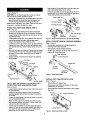
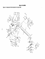
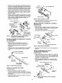
Check for shipping damage. If damage has occurred, a claim
must be filed with carrier. Check for completeness.
immediately report missing parts to dealer.
Your copy crafter is shippedcomplete in one carton.Separate all
parts from packingmaterials and check each one with the
unpackinglistto make certain all items are accountedfor before
discardingany packingmaterial,
if any parts are missing, do not attempt to assemble copy
crafter until the missing parts are obtained and properly
installed.
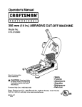
A
Carriage
B
Bracket (2)
C Support Bar with Rack
D Support Bar
E Fine Adjustment Screw
F
Cutting Tool
G Safety Shield
H Guide with Set Screw (Model 24951 only)
I
Follower Assembly
J
Locking Handle (model 24951, qty 1: Model 24952, qty. 2)
K Handle (4)
L
Lever with Grip
M Pattern Support (2)
N Tool Rest Base Assembly (Model 24951 only)
O Carriage Support (Model 24951 only)
P Carriage Support (Model 24952 only)
Q Tool Rest Base Assembly (Model 24952 only)
A
B
D
E
I
Figure1 - Unpacking
Model 24951 Hardware bag (Part No. 18987.00) includes
guide pin, two bracket nuts, four bushings, two pattern bolts,
six spacers, one 5-0.8 x 10mm socket head bolt, one 6-1.0 x
12mm pan head screw, two 8-1.25 x 60ram socket head bolts,
two 8-1.25 x 40mm socket head bolts, four 8-1.25 x 25ram
socket head bolts, four 8-1,25 x 20mm socket head bolts, one
8-1.25 x 10ram set screw, four 8mm fiat washers, one 10ram
fiat washer, two 8-1.25mm hex nuts, two 10-1.5mm hex nuts,
4 and 6ram hex wrenches and 13/14mm open end wrench.
Model 24952 Hardware bag (PN 19078.00) includes guide
pin, two bracket nuts, four bushings, two pattern bolts, six
spacers, one 5-0.8 x 12ram socket head bolt, one 6-1.0 x
12mm pan head screw, two 8-1.25 x 60mm socket head bolts,
two 8-1.25 x 40ram socket head bolts, one 8-1.25 x 30mm
socket head bolt, two 8-1.25 x 25mm socket head bolts, two
8-1.25 x 20mm socket head bolts, four narrow 8ram fiat
washers, two regular 8mm flat washers, two 8ram lock
washers, one 10mm fiat washer, two 8-1.25mm hex nuts, one
10-1.5mm hex nuts, spacer, four 8-1.25 x 8ram set screws,
one 8-1.25 x 10mm set screw, brass pin, 4 and 6ram hex
wrenches and 13/14mm open end wrench.
Insert brasspin intothreaded hole at toolrest supportand
then thread locking handle into the support.
Place tool rest holderontotool rest supportand secure in
positionusingone 8 x 30ram sockethead boltand spacer.
Thread lockinghandle intotool rest holder.
Refer
toFigures
1-9.
CAUTION:
Donotattempt
assembly
ifpartsaremissing.
Usethismanual
toorderreplacement
parts.
• Remove
allcomponents
fromtheshipping
carton
andverify
against
thepartslistabove.
Clean
eachcomponent
and
remove
shipping
preservatives
(coatings)
asrequired.
Socket H::dac::J_.
Tool Rest Holder _
NOTE: Before assembling copy crafter, make sure that lathe
is secured to a suitable workbench or stand.
ATTACH TOOL REST BASE {MODEL
_'_
24951)
t,
Refer to Figure 2.
•
•
•
•
•
•
•
\Pin
Loosentool rest base lockingbar and slidetool rest base
(suppliedwith the lathe)to as near the headstockas possible,
Loosen locking handle of lathe tool rest and remove tool rest
(suppliedwith lathe).
Loosentailstookhandle and remove tailstookfrom lathe bed.
Tool Rest Bracket
Loc_k
Washer
Head Bolt
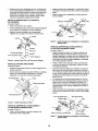
Figure 3 - AttachTool RestBase to Lathe Bed (Model 24952)
Insert guide between bed ways. Slide carnage support
through slotof guideand secure with set screw.
Loosen hex nut from the bottom of tool rest base assembly
supplied with copy crafter so that the clamping plate can
slide between bed ways, Attach locking handle to tool rest
base.
Slide tool rest base onto lathe bed, Positiontool rest bases
approximately 30" apart, Tool rest base will later be adjusted closer or further apart, depending upon the length of
the workpieca.
Replace tsilstock onto lathe bed and secure it by tightening
lockinghandle.
_/TOOl
INSTALL SUPPORT
BARS IN CARRIAGE
Refer to Figure 4,
•
Remove gear assembly from carriage assembly by
removingthree sockethead bolts.
•
•
Slide supportbars into carriage assembly.
Replace gear assembly into the carriage and secure in
positionwith socket head bolts,
_L.f Gear Assembly
'_'_Socket
Heed Belt
sT.
Bar
Screw
J
ASSEMBLY
Rest
_Carriage
:"
Looki ng
Handle
Guide
Tailstock
Assembly
Lockin,
Bar
/J
Support Bar
with Rack
_to_H_a
Ta
Figure 4 - Install Support Bars
ndle
Tool Rest
INSTALL
Locking Handle
Figure 2 - AttachTool Rest Base to Lathe Bed (Model 24951)
ATTACH TOOL REST BASE (MODEL
Refer to Figure 3.
COPY CRAFTER
ONTO LATHE
Refer to Figure 5,
24952)
Loosentailstocklockinghandle and slide it towardthe rear of
the lathe bed tube.
Loosentool rest lockinghandle and slidetool rest base
assembly(suppliedwith the lathe)to as near the headstock
as possible.
Loosenthe lockinghandle of the tool rest holder and remove
toolrest (suppliedwith lathe).
Place tool rest support and bracket onto lathe bed tube
and assemble together using two 8 x 25mm socket head
bolts and two 8ram lock washers.
•
•
Slide brackets onto support bars,
Place spacers over bottom of bracketsand then insert
brackets into tool rest bases,
•
Secure bracketsto supportsbars with 8 x 40ram socket
head bolts,
BsmpCkce_
r_!_
Position tool rest bracket and support assembly approximately 30" from the tool rest base supplied with lathe. Tool
rest bases will later be adjusted closer or further apart,
depending upon the length of the workpiece.
Figure 5 - Install Copy Crafterto Lathe
4
d Bolt
•
,Secure brackets into tool rest bases using lockinghandles.
INSTALL LEVER, HANDLES
ADJUSTMENT
SCREW
AND FINE
Refer to Figure 6.
•
•
Insert bushingsinto lever. Slide 8 x 20mm sockethead bolts
through bushings.Thread bolts into carriage and block.
Thread the four handles with knob intothe hub.
C_
_
Yoke
Follower Assembly
Hex Nut
Socket Head Bolt _
",_
Fine Adj
Screw
INSTALL
i
L
,-<_Socket
Figure6 - Install Leverand Handles
•
Head Bolt
Thread fine adjustment screw with hex nut into block.
INSTALL
CUTTING
"_,_--
Hex Nut
PATTERN
SUPPORT
Refer to Figure 9.
•
Grip
"_'N3uide Pin
_,,_
.L "_-Washer
_'_r-_
Figure 8 - Install Guide Pin and FollowerAssembly
Carriage
Leverwitch
Scre_
TOOL AND SAFETY
Thread pattern bolt and hex nut into pattern support.
Insert 8 x 60mm socket head bolt and fiat washer into slotof
pattern support and bracket and secure in position with
bracket nut.
Bracket Nut
_Bracket
SHIELD
Refer to Figure 7.
Support
Insert cuttingtool into tool holder and use 8 x 10mm set
screw to secure in position.Cutting tool shouldextend out
approximately1W' from holder.
Slide safety shield onto tool holder.Secure in positionwith
pan head screw.
Check height of cuttingtool Cuffing toot shouldbe approximately ',_" above the spindle centedine. Insert canters into
headstock and tailstockspindlesand check tool at each
spindle.If necessary,adjust height by removing spacers
beneath brackets.
Figure 9 - Install Pattern Support
ATTACH
Pan Head Screw--->T
Safety i
CARRIAGE
SUPPORT
TO CARRIAGE
(MODEL 24951)
Refer to Figure 10.
•
Loosen set screw and position carriage support against
carriage.
•
Secure carriage supportto carriage with 8 x 25mm socket
head bolts and fiat washers.
•
Secure carriage supportto guide with set screw.
ToSoo:t
HSo_rd';_'-_ hield "_k _
Washer
'_r'_"Cutting Tool
Carriage Support_
Socket Head Bolt
_,_
Figure 7 - Install CuttingTool and Safety Shield
INSTALL GUIDE
Refer to Figure 8.
PIN AND FOLLOWER
ASSEMBLY
Remove protectivepaper from cover.
Insert guide pin into slot of yoke. Secure in positionwith
washer and hex nut.
•
Bed
Slide follower assembly onto guide pin.Secure in position
with socket head bolt.
Figure 10 - Attach Carriage Support to Carriage (Model 24951)
5
, ATTACH CARRIAGE
(MODEL 24952)
Refer to Figure 11.
SUPPORT
TO CARRIAGE
WARNING: Operation of any power tool can result in foreign
objects being thrown into the eyes, which can result in severe
eye damage. Always wear safety goggles complying with
United States ANSI Z87.1 (shown on package) before commencing power tool operation. Safety goggles are available at
Sears retail stores or catalog.
Insert upper guide rod into carriage support bar until end is
flush with opposite face, Make sure fiat on guide rod faces
down, so that flat will ride on the top surfaceof the bed tube,
Secure in positionwith 8ram set screw,
CAUTION:
Insert end of lower guide rod completely into carriage support bar. Note that this guide rod is eccentric.
SAFETY
Place guide roller under key on bed tube. Slide lower guide
rod throughguide roller,with upper guide rod over the top of
the bed tube. Race plate over both guide rods. Secure the
upper guide rod only usingan 8mm set screw.
• Recheckall lockinghandles.They must be tightened secarely
•
Using a 13mm open end wrench on the fiats of the lower
guide red, adjust rod so that the carriage supportslides firmly withoutbinding on the bed tube. Secure the lower guide
rod in position with two 8mm set screws.
•
Always observe the following safety precautions:
Secure carriage support to carriage using8 x 25ram socket
head bolts and flat washers.
Socket Head
Fiat Washer
Upper Guide Rod
Plate
Carriage Support Bar
Make sure all moving parts are free and clear of any
interference.
•
Make sure all fasteners are tightand have not vibrated loose.
•
With power disconnected, test operation by hand for clearance and adjust if necessary.
•
Always wear eye protection or face shield.
•
After turning switch on, always allow the spindle to come
up to full speed before turning.
•
Be sure spindle runs counterclockwisewhen viewing
spindle from the tailstock end.
•
Keep hands clear of spindle, centers, faceplatas and other
moving parts of machine.
•
For optimum performance, do not stall motor or reduce
speed. Do not force the tool into the work.
ADJUSTMENT
Roller
•
Lower Guide Rod
Figure 11 - Attach Caniage Supportto Carriage (Model 24952)
Before starting,the cuffingtool must be set approximately
%" above the spindle.Check tool heightat both the headstock and the tailstock.
Vertical adjustment can be made by looseninghandles
which secure the vertical brackets and adding or removing
spacers.The tool rest bases can also be moved horizontally
across or along the lathe bed, towardsor away from the
spindle.
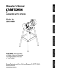
Refar to Figures 12, 13 and 14 (pages 7, 10 and 12).
DESCRIPTION
In orderfor the copy crafter to function properly,the distance
from the cuttingtool to the lathe spindle centadine must be
equal to the distancefrom the follower assembly to pattern
bolt centedine.This can be accomplishedby mountingidentical sized stock in the lathe and on the pattern bolts.Adjust
the copy crafter so that the cuffingtool touches the stock
mounted in the lathe and the follower assemblytouches the
stock mounted in the pattern bolts.The copycrafter can be
adjusted by moving the pattern supports,movingthe tool
rest bases across the lathe bed or adjustingthe yoke on the
tool holder.
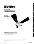
Craftsman Copy Crefters provide the Craftsman Wood Lathes
with the capability to reproduce spindles and posts up to 38"
long. Model 24951 is designed for use on lathes 21715 end
21717. Model 24952 is designed for use on lathe 21712. It will
produce duplicate workpieces from either an original spindle
or a template. It can also copy shallow faceplate turnings up
to 4" in diameter. The copy crafter features a cast aluminum
carriage that rides on parallel steel rails, a steel guide pin with
follower that maintains pattern contact to reproduce detailed
shapes, cutting depth that can be set with fine adjustment
screw or turret which has preset depth adjustments at V_"
increments up to 1", four-spoke handwheel with reck and
pinion drive, mounts to two tool rests (1 is included), and
includes a resharpenable, replaceable high speed steel chisel
bit.
DUPLICATE TURNING
SPECIFICATIONS
Turning length (max.) .............................
Bowl diameter (max.) ..............................
Overall length ...................................
Overall height ...................................
Width .........................................
Original spindle diameter (max.) .....................
Template width (max.) ............................
Weight ......................................
Whenever adjusting or replacing any parts on the tool, turn
switch OFF and remove the plug from power source.
•
Screw
Key
PRECAUTIONS
38"
4"
42"
19"
22"
5"
2W'
45 Ibs
•
Mount the original in the pattern bolts.The tool rest bases
will need to be adjusted along the lathe bed to the required
length.
•
When starting with a square piece of stock, that will be
reduced to a cylinder, use the turret stop and take light cuts
until the cylinderhas been formed.
NOTE: Do not start out on the end of the workpiece, as the
tool may become caught and damage the workpiece.
6
•
Turn the workpieca to a cylinder slightlylarger than final
size. At this time adjust the follower assembly against the
odginal.
•
Glide the tool holder along the support bars to duplicate the
odginal piece.
NOTE: Sharp corners and small grooves will only be partially
duplicated by the copy crafter. The follower assembly will
need to be removed. Using calipers, transfer measurements
from original to duplicate, and clean up grooves and corners
using fine adjustment screw on carriage.
WARNING:
MISCELLANEOUS OPERATIONS
•
Make certain that the lathe is disconnectedfrom
power source before attempting to service or remove any
component.
CLEANING
The copy crafter can also be used to taper workpieces.To
do this, offset the tool rest bases.
•
The copy crafter can be mounted across the bed for copying
of bowls, cups, etc. by repositioningtool rest bases.
•
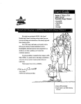
The copy crafter can trace a template as well as an original
spindle.
•
The template represents the profileof the post measured
from its centedine.
•
The measurements of the post are transferredto a suitable
material such as '/," plywood laid out and cut on a band,saw
or scrollsaw.
Keep machine and workshop clean. Do not allow sawdust to
accumulate on the tool.
Use soap and water to clean painted parts, rubber parts and
plastic guards.
LUBRICATION
The shielded ball bearings in this tool are permanently lubricated at the factory. They require no further lubrication.
KEEP TOOL IN REPAIR
Replace any damaged or missing parts. Use parts list to
order parts.
•
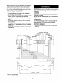
The template is then bolted to the pattern supports,parellel
to the lathe bed.
•
Figure 12 on page 7 shows an example br usinga template.
¢34
'925
'a40005
_32.004
=19.05
[07'5]
_4L628
¢,11112
[1373
[0441
C157]
,_292]
[115]
,_29.2_
[1.26]
¢I6
724
COGG]
_2794
,1,27
[063]
_ 16064
94
It
1_3
m254
[1.641
[1¸101
c]oo]
37.8_4
_110_
=190_
C149_
[0751
\
/[020]
28
8134
[1 3]
43778
[172]
64991
[2.561
132
678
[5_2]
156.078
[(= 22]
] 75.26
[6903
182_8
[720]
199¸689
[786_
2197t
[865]
Z268_t
t2.7
[0.50_
224
[869J
79
[8853
127
_8.5
I
.19.05 [0.75]
W
250.19
Figure 12 - Using a Template
7
[9,85]
19.05 C0.7
C0503
[0.335]
[.,_
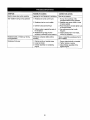
SYMPTOM
POSSIBLE CAUSE(S)
CORRECTIVE ACTION
Machine slows down while operating
Applying too much pressure to workpiece
Ease up on pressure
Tool =chatters" during turning operation
1. Workpiece is too far out-of-round
1 True up the roundness of the
workpiece before turning operation
2. Establish new center marks on ends
to reduce wobble
2. Workpiece has too much wobble
3. Operator using bad technique
3. Read instructionsand take lightercut.,
to minimize chatter
4. Cutting motion is against the grain of
the workpiece
5. Workpiece is too long and thin work-pieceis deflected bytool pressure
4. Use cutting motion that is with
the grain
5. Install a steady rest in the middle,
behind the workpiece
Workpiece splits or "breaks up"during
turning operation
Workpiece contained defects before
mounting
Select or assemble a workpiece that is
free of defects
Workpiece finish poor
1. Original spindle or template loose
2. Loose tool holder
1. Secure original spindle or template
2. Tighten tension on spring
3. Adjust follower assembly firmly
against original
3. Follower assembly not contacting
original
8
Service Record
Craftsman Copy Crafter
DATE
MAINTENANCE PERFORMED
REPLACEMENT PARTS REQUIRED
9
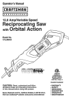
1
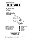
Model
351.249510
Figure 13 - Replacement Parts Illustration for Copy Crafter
11
6
12
7
2
63
4
KEY
NO.
1
2
3
4
5
6
7
8
9
10
11
12
13
14
15
16
17
18
19
20
21
22
23
24
25
26
27
28
29
30
31
32
33
34
35
36
37
PART NO.
18195.00
18196.00
18197.00
18198.00
02025.00
18199.00
STD840812
20047.00
18201.00
STD851008
18202.00
18203.00
00519.00
18104.00
06974.00
06976.00
_05358.00
18103.00
18102.00
18101.00
00179.00
00964.00
18204.00
18205.00
18206.00
18207.00
BTD841015
18208.00
18209.00
01822.00
03855.00
09732.00
18211.00
06182.00
STD840610
STD833030
18212.00
DESCRIPTION
Carriage
Bushing
Support Bar
Support Bar with Rack
8-1.25 x 40mm Socket Head Bolt
Bracket
8-1.25mm Hex Nut*
Spacer
Pattern Support
8ram Flat Washer*
8-1.25 x 60mm Socket Head Bolt
Pattern Bolt
3AM I-12 Retaining Ring
Locking Handle
12-1.75 x 30ram Eye Bolt
Clamping Plate
12-1.75mm Fiber Hex Nut
Tool Rest Holder
Bushing
Locking Bar
6-1.0 x 20mm Socket Head Bolt
6-1.0 x 6mm Set Screw
Bushing
Shaft
Yoke
Guide Pin
10-1.5mm Hex Nut*
Bushing
Leverwith Grip
8-1.25 x 20mm Socket Head Bolt
5-0.8 x 10mm Socket Head Bolt
8-1.25 x 35mm Socket Head Bolt
Fine Adjustment Screw
6-1.0 x 3Omm Socket Head Bolt
6-1.0ram Hex Nut*
6-I.0 x 30mm Hex Head Bolt*
Spring
Standard hardware item available locally.
Z_ Not Shown
QTY.
1
4
1
1
2
2
2
6
2
4
2
2
2
1
1
1
1
1
1
1
2
1
2
1
1
1
2
4
1
2
1
1
1
1
2
2
1
KEY
NO.
38
39
40
41
42
43
44
45
46
47
48
49
50
51
52
153
: 54
55
56
57
58
59
60
61
62
63
64
65
66
67
68
69
70
71
A
&
PART NO.
05331.00
18213.00
18214.00
18215.00
18216.00
16217.00
18218.00
07202.00
18219.00
18220.00
18221.00
01596.00
20048.00
18222.00
)0781.00
18223.00
18224.00
01465.00
01282.00
18226.00
18227.00
18228.00
STD851010
18230.00
00348.00
20051.00
06396.00
18233.00
18235.00
00483.00
00351.00
20050.00
20049.00
20052.00
18987.00
18234.01
DESCRIPTION
5-0.8 x 12mm Socket Head Bolt
Bushing
Cam Plate
Plunger
Spring
Block
Tool Holder
8-1.25 x 10mm Set Screw
Rod
Cutting Tool
Bushing
6 x 20mm Spring Pin
Follower Arm
Cover
4-0.7 x 8mm Pan Head Screw
Gear
Collar
3AMI-30 Retaining Ring
8-1.25 x 6ram Set Screw
Knob
Handle
Hub
10mm Flat Washer*
Safety Shield
6-1.0 x 12ram Pan Head Screw
Carriage Support
3 x 12ram Spring Pin
Guide
Bracket Nut
8-1.25 x 25ram Socket Head Bolt
6-1.0 x 10mm Set Screw
Spring
Follower Bearing
Follower Assembly (Includes Key Nos. 50, 64 and 70)
Hardware Bag
Operator's Manual
QTY.
4
1
1
1
1
1
1
2
1
1
2
1
1
1
4
1
1
1
1
4
4
1
1
1
1
1
1
1
2
2
1
1
1
1
1
1
Model
351.249520
Figure 14 - Replacement Parts Illustration for Copy Crafter
62_
!
lO
/
24
/
23
8
9
10
KEY
NO.
KEY
PART NO.
DESCRIPTION
1
18195.00
Carriage
QTY.
1
NO.
PART NO.
DESCRIPTION
38
18212.00
4
39
05331.00
Spring
5-0.8 x 12ram Socket Head Bolt
2
18196.00
Bushing
3
18197.00
Support Bar
1
40
18213.00
4
5
18198,00
02025,00
1
41
2
18199,00
Support Bar with Rack
8-1.25 x 40ram Socket Head Bolt
Bracket
6
2
7
18235.00
Bracket Nut
5
18201.00
9
QTY.
1
5
1
18214,00
Bushing
Cam Plate
42
18215,00
Plunger
1
18216,00
Spring
Block
1
2
43
44
STD851008
Pattern Support
8ram Flat Washer*
2
4
45
46
Tool Holder
8-1.25 x 10rnm Set Screw
1
1
10
18202.00
8-1.25 x 60mm Socket Head Bolt
2
47
18218.00
07202.00
118219.00
Rod
1
11
12
18203.00
STD840812
Pattern Bolt
2
48
;18220.00
Cutting Tool
1
8-1.25mm Hex Nut*
2
49
18221,00
Bushing
2
13
00732.00
1
1
5O
51
15
18163.00
1
52
STD833030
18222.00
6 x 20ram Spring Pin
6-1.0 x 30turn Hex Head Bolt*
1
18164.00
5-1.25 x 30ram Socket Head Bolt
Tool Rest Holder
01596,00
14
1
4
18217.00
1
1
1
16
18160.00
Tool Rest Support
Tool Rest Bracket
1
53
00781.00
Cover
4-0.7 x 8ram Pan Head Screw
17
STD552008
8ram LockWasher*
2
54
18223.00
Gear
1
18
19
00483.00
18161.00
8-1.25 x 25mm Socket Head Bolt
Pin
4
55
18224.00
Collar
1
1
56
01465.00
1
20
18162.00
21
00179.00
Locking Handle
6-1.g x 20ram Socket Head Bolt
2
2
57
58
18225,00
18226,00
3AMI-30 Retaining Ring
8-1,0 x 6ram Set Screw
Knob
22
00964.00
6-I.0 x 6turn Set Screw
1
59
18227.00
Handle
4
23
24
18204.00
18205.00
Bushing
Shaft
2
60
18228.00
Hub
1
1
61
18230.00
1
25
18206.00
Yoke
26
18207.00
Guide Pin
1
1
62
63
03812,00
18237.00
Safety Shield
6-1,0 x 10ram Pan Head Screw
27
STD851010
10mm Flat Washer*
1
64
18238.00
28
29
STD841015
18208.00
10-1.5mm Hex Nut*
2
65
Bushing
4
30
31
18209.00
01822.00
Lever with Grip
8-1.25 x 20ram Socket Head Bolt
1
32
20048.00
Follower Arm
2
1
68
( 69
33
34
09732.00
18211.00
8-1.25 x 35ram Socket Head Bolt
1
7O
Fine Adjustment Screw
1
71
35
36
06152.00
STD840610
6-1.0 x 30turn Socket Head Bolt
6-1.0mm Hex Nut*
1
2
37
16348,00
6-1.0 x 35mm Hex Head Bolt
A
Standard hardware item available locally.
Not Shown
1
4
Carriage Support Bar
1
1
00958.00
Upper Guide Rod
8-1.25 x 8ram Set Screw
4
66
18240.00
Lower Guide Rod
1
67
18241.00
18242.00
Guide Roller
1
Plate
20052.00
1
1
20047.00
Follower Assembly (includes Key Nos. 32. 72 and 73)
Spacer
6
20089.00
Spacer
1
72
06396,00
3 x 12rnm Spring Pin
1
73
20049,00
19078.00
Follower Bearing
1
1
Hardware Bag
1
TRAZADOR
•
Modelo No.
351.249510
351.249520
PRECAUClON:
Lea y siga todas las Reglas
de Seguridad y las Instrucciones de Operaci6n
antes de usar este producto por primera vez.
Ingles .........................................
•
Use una m_scara para la cara o una m=_scara contra el polvo,
sial utilizar la sierra se produce mucho polvo.
•
Est_ alerta y piense claramente. Nunca opere herramientas
mecdnicas cuando este cansado, intoxicado o bajo la infiuencia de medicacibn que produzca somnolencia.
PREPARACION DEL AREA PARA EJECUTAR
EL TRABAJO
•
Mantenga el &rea de trabajo limpia. Las _reas de trabajo
desordenadas atraen accidantes.
•
No use harramientas mecdnicas en ambientes peligrosos. No
use herramientas mec&nicas en lugares hemedos o mojados.
No exponga Las herramientas mecdnicas a la Iluvia.
•
El drea de trabajo debe estar iluminada adecuadamente.
•
Mantenga a los visitantes a una distancia prudente del drea
de trabajo,
•
Mantenga
taller sea
maestros
cualquier
2-8
Ilustracibny Lista de Partes ......................
10-13
Garantia ........................................
14
Reglas de Seguridad ...........................
14-15
Desempaque
15-16
.................................
Montaje ......................................
16-18
Operaci6n ....................................
19-20
Mantenimiento ...................................
Identiflcaci6n de Problemas .........................
20
21
SE DEBE
GARANTIA COMPLETA DE UN Al_lO
Si fallara este preducto por causa de defectos en el matedal
o en la mano de obra en un lapso de un aSo a partlr de la
feeha de compra, Sears Io repamrd o reemplazar_, a su
eleccibn, sin costo adicionaL Solicite a[ Centro de servicio
a los niSos fuera del lugar de trabajo. Haga que su
a prueba de nifios. Use candados, interruptores
y remueva las Ilaves del arraneador para impedir
uso involuntado de las herramientas mecdnicas.
DAR MANTENIMIENTO
A LA HERRAMIENTA
•
Desenchufe siempre el torno antes de inspeccionarlo.
•
Consulte el manual para informarse sobra los procedimientos
de mantenimiento y ajuste especiflcos.
•
Mantenga la herrsmienta lubricada y limpia de modo que funcione de la manara m_s segura.
•
Mantenga todas las partes listas para funcionar. Revise el
protector u otras piezas para determinar si funcionan correctarnente y hacen el trabajo que deben hacer.
Sears (1-8OO-4-MY-HOME) mds cercano la reparaci6n del
producto o devu_lvalo al establecimiento donde Io adquiri6.
•
Revise que no haya partes dafiadas.Verifique el alineamiento
de las partes m6viles, si hay atascamiento, roturas y rnontaje
o cualquier otra condici6n que pudiera afectar el funcionamiento de la herramienta.
•
Si hay una protecci6n o cualquier otra parte daSada, _stas
Si este producto se usa para fines comerciales o de alquiler, esta
garanfia es v&lida por 90 dfas a partir de la fecha de compra.
Esta garanfia aplica 0nicamente
Estados Unidos.
Use gafas de seguridad que cumplan con la norma ANSI
Z87.1 de los Estados Unidos, Los anteojos comunes tienen
lentes que s61o son resistentes al impacto. NO son anteojos
de seguridad.
si el producto se utillza en los
deberdn repararse correctamente o ser reemplazadas. No
haga reparaciones provisionales (v_lgase de la lista de partes
incluida para solicitar piezas de repuesto).
Esta garant{a le otorga derechos legales especiflcos y tambi6n
puede usted tener otros derechos que varien de estado a estado.
•
Nunca ajuste el trazador cuando el torno se encuentre funcionando. Desconecte la potencia para evitar que la herramienta
se encienda por accidenta.
•
Mantenga las herramientas de corte afiladas para obtener un
funcionamiento seguro y eficiente.
Sears, Roebuck and Co., Dept. 817WA, Hoffman Estates,
IL 60179
EL OPERADOR DEBE SABER COMO USAR
LA HERRAMIENTA
PRECAUCION:
Siempra siga los procedimientos de operacibn
correctos, tal como se definen en este manual, aun cuando est6
familiarizado con el uso de esta o de otras herramientas simi-
•
Use la herramienta
correcta para cada trabajo. No fuerce la
herramienta o el accesorio ni los use para una tarea para Is
que no fueron diseSados.
lares. Recuerde que descuidarse aunque s61o sea por una fracci6n de segundo puede ocasionarle graves lesiones.
•
Use ropa apropiada. No use ropa holgada, guantes, corbatas,
anillos, pulseras ni otras joyas que puedan atascarse en las
piezas m6viles de la mdquina.
Evite que la harramienta se encienda pot accidante.
AsegSrese de que el interrupter de la hermmien_ est_ en la
posici6n OFF (apagado) antes de enchufarla y encienda ]a
desconexi6n de seguridad o active los interruptores.
•
No fuerce la herramienta, Funcionard en La forma rods eft*
•
Use una cubierta protectora para el cabello, para sujetar el
cabello largo.
•
Mantenga las manos alejadas del portaherramientas, los cantros y de otras partes m6vilas,
•
Use zapatos de seguridad con suelas antideslizantes.
•
Nunca deje desatendida una herramienta en funcionamiento.
EL OPERADOR DEBE ESTAR PREPARADO
PARA EL TRABAJO
•
ciente a la velocidad para la cudl se dise56,
Descondctela y no abandone el lugar hasta que se haya
detenido por completo,
14
•
No trate de alcanzar demasiado lejos. Mant6ngase flrrne y
equilibrado.
•
Nunca se pare sobre la herramienta. Se pueden producir
lesiones graves si la herramienta se vuelca o si entra en contacto con los centros sin intencibn.
Pare su propia seguridad, lea todas les reglas y precauciones
incluides en el manual del operador antes de utilizer la herrarnienta.
Pera proteger sus ojos, pbngase galas de seguridad que
cumplan con la norma ANSI Z87.1 de los Estados Unidos.
Conozca su herTamienta. Aprenda a rnanejar la herramienta,
su aplicaci6n y limitaciones especificas.
No use ropa holgada, guantes, corbates, anillos, pulseras ni
otras joyes que puedan atascarse en las piezas m6viles de la
m_quina o en la pieze de trabajo. Use una cubierta protectore
para el cabello, para sujeter el cabello largo.
Maneje la pieza de trabajo en forrna corTecta. Inst_lela firmemente en los dispositivos de sujeci6n. Prot6jase las manos de
posibles lesiones.
•
Apdete todas las abrazaderas, accesorios y el cabezal rnbvil
antes de eplicar le potencia. Revise pare asegurarse que se
heyan retirado todas las herramientas y Ileves.
de corte como se recorniende en la
•
ADVERTENCIA:
Pare su propia seguddad, no opere el trazadot sino haste que este completamente montado e instelado
seg0n las instrucciones.
Con el interruptor apagado, gire la pieza de trebajo con la
meco pera asegurarse que haya suficiente espacio nbre.
Arranque la mdquina en el ajuste de velocided m_s bejo pare
verificar que la pieza de trabajo se encuentre esegurada.
•
No monte piezas de trabajo que tengan hendiduras o nudos.
•
Apague le herramienta si la pieza de trabejo se parte o se
suelta.
•
Utilice las herramientas
seccibn "Operacibn".
•
PROTECCION:
OJOS,
MANOS,
CARA,
CUERPOY
OIDOS
Si falla o falta elguna pieza del trazador, o si se ha quebrado
o dafiado, suspende inmediatamente el funcionamiento de la
herramienta hasta que la pieza en cuestion sea reparada o
reemplazada correctamente.
Use galas de seguridad que cumplen con la norma ANSI
•
Cuendo vuelva a montar un torneado entre centros cuyos
centros origineles no hen sido alternedos, asegt_rese que la
velocidad de arranque se encuentre en el ajuste mds bajo.
•
Sea sumarnente cuidadoso al montar un tomeado entre centres en la place de sujecion, o un tomeado de place de sujeci6n a entre eentros, para operaciones secundarias. Aseg0rese
que la velocidad de arranque se encuentre en el ejuste rods
bajo.
Z87,1 de los Estados Unidos y una rndscara para la cara o
una mdscara contra el polvo, sial utilizer la herramiente se
produce mucho polvo. Use audffonos u orejeras al utilizar la
herramienta durente periodos prolongedos.
Las piezas pequefias de rnadere u otros objetos que entren
en contacto con una pieza de trabajo en g!ro pueden ser
pmyectadas a una velocidad sumamente alta. Esto puede
evitarse rnanteniendo el drea de trabejo lirnpie,
•
Nunca intente volver a montar un torneado entre centros si los
centros odginales en el mismo hen sido alterados o retirados.
•
Nunca reelice une operaci6n con esta herramienta si la pieza
de trabajo se sujeta con la mano. No monte un escadador,
fresa, broca, ruedes de cables o ruedas pulimentadoras en el
husillo del cabezal fijo.
•
Nunca haga girar el husillo en la direcci6n incorrecta. La
Antes de comenzer el funcionarniento, retire del trezador y del
torno toda herramiente, restos de rnadera, etc., salvo le pieza
de trabajo y les herramientas neceserias.
herramienta de corte podda zafdrsele de las manos. La pieza
de trabajo deberd siempre girar en direcci6n de operador.
•
Nunca ponga la cara o el cuerpo en linea con el portaherramientas o laplaca de sujeci6n.
Cuendo haga girar el husfllo, SIEMPRE coloque el soporte de
la herramienta por encima de la linea central de la pieza de
trabajo y del husillo (aproximadamente Vs").
Nunca coloque sus dedos o manos en la trayectoria de herramientas de corte,
•
Nunce elcence hecie la perte posterior de le pieze
con cualquiera de las manos pare apoyar la pieza
remover los restos de madere o por cualquier otra
Evite operaciones dificiles y no coloque las rnenos
de trabejo
de trabajo,
raz6n.
en sitios
Consulte
donde pudieran resbalarse ocasionando que los dedos o toda
la rnano se rnuevan hacia una pieza de trabajo en gire.
Si la pieze de trabajo se parte o dafia de alguna manera,
APAGUE el torno y retire la pieze de trebajo de los fladores.
Descar_e la pieze de trebajo dafiada y comience con una
nueva pieze de medera.
•
Su trazador se env[a completo en una caja. Separe todas las
partes de los rnateriales de empaque e inspeccione la liste de
partes para asegurar que se hayan incluido todas las pertes
antes de descartar el material de empeque.
Tenga especial cuidado cuando tomee madera con veta torcida o madera que est6 toreida o cornbada - podrie cortarse
de manera dispereja y tambalearse de forme excesiva.
Si faltan pertes, no intente montar el trezador haste que se
obtengen e instelen correctamente les partes faltantes.
A
CONOZCA
SUS HERRAMIENTAS
la Figure 1 en la pdgina 16.
Verifique que no hayan ocurrido dafios durante el envio. Si hay
dafios, se deberd presenter un reclamo a la cornpafiie de transporte. Verifique que estd completa. Avise inmediatamente el distribuidor si feltan partes.
DE CORTE
Deslizadera
B Puntal (2)
Les herrarnientas de corte desafiladas, gomosas o que no se
hen afilado o preparado correc_amente pueden ocasionar
vibraci6n y tintineo durante les operaciones de corte. Reduzca
a un minimo la posibilidad de lesiones teniendo el cuidado
C Barra de soporte con cremallere
D Barra de soporte
adecuedo y dando el mantenimiento regular correcto ala
m_quina.
E
Torniffo de ajuste fino
F
Herramienta de corte
G Resguardo de seguddad
PIENSE EN LA SEGURIDAD
H Guia con tornillo de fijecibn (modelo 24951 solemente)
La seguridad es el resultado de una eombinaci6n entre el sentido
cornL'mdel operedor y el mentenerse alerta en todo momento
mientras se estd utilizendo el toreo.
15
I
Conjunto del palpador
J
Menija de fijaci6n (modelo 24951, cantidad 1: modelo 24952,
cantJdad 2)
K
Mar_ija (4)
INSTALE
L
Palanca con agarre
(MODELO
LA BASE DEL SOPORTE
DE LA HERRAMIENTA
24951)
M Soporte pars patr6n (2)
Consuite la Figure 2,
N Conjunto de la base del soporte de Is herramienta
(modelo 24951 solamente)
•
Afloje la barfs de fijaci6n de la base del seporte de la herramienta y deslice la base del soporte de la hermmienta (suministrada con el torno) tan cerca del cabezal fijo corno sea
posible.
•
Afloje la manija de fijaci6n del soporte de la herramienta del
torno y retire el seporte de la herramienta (surninistrado con
el tome),
•
Afloje la msnija del cabezal mbvil y retire el cabezal rnbvil de
la base del tomo.
•
Inserte la gu[a entre las viss de la base. Deslice el soporte de
la deslizadera a tmv6s de la ranura en la guia y asegL_relo
con el tornillo de fijacibn.
•
Afloje la tuerca hexagonal de la parte inferior del conjunto de
la base del soporte de la herramienta suministrada con el
trazador de manera que laplaca de sujecibn pueda
deslizarse entre las vies de la base. Acople la manija de
fijecibn ala base del soporte de la herramienta.
•
Deslice la base del seporte de la herramienta en la base del
torno. Coloque las bases del soporte de la herramienta a una
distancia aproximada de separacibn de 30". Luego, la base
O
Soporte de la deslizadera (modelo 24951 solamente)
P
Soporte de la desiizadera (modelo 24952 solamente)
Q Conjunto de la base del soporte de la herramienta
(modelo 24952 solamente)
A
B
G
I
Figure 1 - Desempaque
del soporte de la herramienta se podr_ acercar o separar
m&s, dependiendo del largo de Is pieza de trabajo.
Modelo 24951 La bolsa de artfculos de ferreter{a (No. de Parte
18987.00) incluye pasador guia, dos tuercas pars puntal, cuatro
bujes, dos pernos pars patrones, seis espaeiadores, un perno de
cabeza hueca de 5-0.8 x 10ram, un perno de cabeza de placa de
6-1.0 x 12ram, dos pernos de cabeza hueca de 8-1.25 x 60mm,
dos pernos de cabeza hueca de 8-1.25 x 40mm, cuatro pernos
de cabeza hueea de 8-1.25 x 25mm, cuatro pernos de cabeza
hueca de 8-1.25 x 20turn, un tornillo de fijaci6n de 8-1.25 x
1Omrn, cuab'o arandelss planes de 8rnm, una ar_ndela plana de
1Ornrn, dos tuercas hexagonales de 8-1.25rnrn, dos tuercas
hexagonales de 10-1.5mm, Ilaves hexagonales de 4 y 6 mm y
una Uave de extremo abierta de 13/14mm.
•
Vuelvs a colocar el cabezal mSvil en la base del torno y
aseg0relo apretando la manija de fijacibn.
_/,Soporte
_J
de la herramienta
.
Tornillo de fijaci6n
Soporte
de la
desfiza_
Gu{a
Cabezal m6vil
/
Modelo 24952 La boise de artfculos de ferreter[a (No. de Parte
19078.00) incluye pasador gala, dos tuercas pars puntal, cuatro
bujes, dos pernos pars petrones, seis espaciadores, un perno de
Barrad
M
fijaci6n
cabeza hueca de 5-0.8 x 12turn, un perno de cabeza de placa de
6-1.0 x 12turn, dos pernos de cabezs hueca de 5-1.25 x 60mm,
dos pernos de cabeza hueca de 8-1.25 x 40ram, un perno de
cabeza de hueca de 8-1.25 x 30mm, dos pernos de cabeza
/"
bezal mdvil
Base del :
de la herramienta
Manija de fljacibn
hueca de 8-1.25 x 25turn, dos pernos de cabeza hueca de 8-1.25
x 20mm, cuatro arandelas planes delgadas de 8rnm, dos arandelas planes regulates de 8rnm, dos arandelas de seguridad de
8ram, una arandela plans de 10mm, dos tuercas hexagonales
de 8-1.25mm, una tuerca hexagonal de 10-1.5turn, espaciador,
Figura 2 - Acople la Base del Soporte de la Herramienta a la
Base del Tomo (Modelo 24951)
INSTALE
(MODELO
cuatro tornillos de fijacibn de 8-1.25 x 8mm, un tornillo de fijaci6n
de 8-1.25 x 10mrn, pssador de latbn, Ilaves hexagonales de 4 y
6 mm y una Ilave de extremo abierto de 13/14mm.
LA BASE DEL SOPORTE
DE LA HERRAMIENTA
24952)
Consulte la Figura 3.
•
Afioje la manija de fljacibn del cabezal mbvil y deslicelo hacia
la parte posterior del tubo de la base del torno.
•
Afloje la manija de fljacibn de la base del seporte de la heiTernienta y deslice el conjunto de la base del seporte de la herramienta (surninistrado con el torno) tan eerca del cabezal
fijo como sea posible.
•
Afloje la manija de fljacibn de[ fiador del soporte de la herrarnienta y retire el soporte de la herramienta (suministrado con
el torno).
•
Coloque el apoyo del soporte de la herramienta y el puntal en
el tubo de la base del torno e instdlelos juntos utilizsndo dos
pernos de cabeza hueca de 8 x 25rnm y dos arandelas de
seguridad de 8ram.
Consulte las Figures 1-9.
PRECAUCION:
No intente hacer el montaje si hay partes que
faltan. Vdlgase de este manual pars solicitar piezse de repuesto.
Retire todos los componentes de la eaja de envio e inspeccione la lists de partes para vedfiear que se hayan incluido
todas las partes. Limpie cads uno de los componentes y retire
todo agente de conservacibn (recubrimientos) seg0n sea
necesario.
AVISO: Antes de rnontar el trazadar, eseg0rese que el torno este
afisnzado aun banco de trabajo o soporte adecuado.
16
•
_oloque el conjunto del apoyo y puntal del soporte de la herramienta a una distancia aproximada de 30" de la base del
Puntal_
Espaciador
soporte de la herrarnienta suministrada con el tomo. Luego,
las bases del soporte de la herramienta se p_:lr_n acorcar o
separar m_s, dependiendo del Largode La pieze de trabajo.
Inserte el pasador de latSn en el oriflcio roscado del apoyo
del soporte de la herTamienta y luego enrosque la manija de
fljacibn en el apoyo.
•
Coloque el fiador del soporte de la herramienta en el apoyo
del soporte de la herramienta y asegOrelo en su posici6n utilizando un perno de cabeza hueca de 8 x 3Omm y un espaciador. Enrosque la manija de fijaci6n en el fiador del
soporte de Is herrarnienta.
Figura 5 - Instale el Trazador an el Tomo
•
Pemo de cabeza hueca
Espaciador _,
INSTALE LA PALANCA,
DE AJUSTE FINO
Fiador del soporte de
la herramienta
Apoyo del soporte
de la herramienta _
Asegure los puntales en les bases del soporte de la herramienta utilizando las manijas de fijaci6n.
LAS MANIJASY
ELTORNILLO
Consulte la Figura 6.
I
•
Inserte los bujes en la palanca. Deslice los pernos de cabeza
hueca de 8 x 20mm a trav6s de los bujes. Enrosque los pernos en la deslizadera y el bloque.
•
Enrosque las cuatro manijas con perilla en el cobo.
Manija de
de la herramienta
cabeza hueca
Arandela de seguridad
Tuerca hexagonal
Figure 3 - Acople la Base del Soporte de la Herramienta
a la Bass delTomo (Modelo 24952)
Tornillo de a
rico
_-->-
Deslizadera
INSTALE LAS BARRAS DE SOPORTE EN EL CONJUNTO
DE LA DESLIZADERA
Consulte la Figura 4.
Retire el conjunto de engranejes del conjunto de la
deslizadera extrayendo tres pernos de cabeza hueca.
con agarre
<E_°emo
Deslice las barras de soporte en el conjunto de la
deslizadera.
•
Vuelva a colocar el conjunto de engranajes en la deslizadera
y asegL'Jreloen su posicibn utilizando pernos de cabeza
hueca.
•
Consulte la Figura 7.
Perno de cabeza hueca
•
/
•
Deslice el resguardo de seguridad en el fiedor de la herramienta. Asegtirelo en su posici6n con un tornillo de cabeza
de place.
Tornillo de cabeza de place -_--_
Resguardo
•
.
de seguridad
!
Tornlllo de fijaci(Sn-._...._
"_/_.
Barra de soporte
con cremallera
Figure 4- Instale las Bar'as de Soporte
EL TRAZADOR
Inserte la herramlenta de eorte en el fiador de la herramienta
y utilice el tornillo de fijacibn de 8 x 10mm para asegurarla en
su posicibn. La herramienta de corte debe extenderse aproximadamente 1V2"m_ls alld del fiador.
Barra de soporte
INSTALE
Enrosque el tornillo de ajuste fino con la tuerca hexagonal en
el bloque.
INSTALE LA HERRAMIENTA DE CORTEY
EL RESGUARDO DE SEGURIDAD
Conjunto de engranajes
Conjunto de
la deslizadera
de cabeza hueca
Figure 6 - Instale la Palanca y las Manijas
EN EL TORNO
Fiador de la he _rramien_.
--T
Consufte la Figure 5.
•
Deslice los puntales pot las bah'as de soporte.
•
Coloque los espaciadores sobre la parte inferior de los puntales y luego inserte los puntales en les bases del soporte de
[a herramienta.
•
Asegure los puntales alas barras de soporte con pernos de
cabeza hueca de 8 x 40mm.
Figura 7 - Ins-tale la Herramienta de Corte y el Resguardo
de Seguridad
17
•
VeriRque la altura de la herTamienta de corte. La herramienta
de corte debe quedar aproximadamente V_" por encirna de Is
linea central de1 husillo. Inserte los centros en los husillos del
•
cabezal fijo y del cabezal m6vil, y revise la herramienta en
cada uno de los husillos. De ser necesado, ajuste la altura
retirando los espaciadores debajo de los puntales.
•
INSTALE EL PASADOR
DEL PALPADOR
GUIAY
Asegure el soporte de la deslizadera
ala deslizadera utilizan-
do los pernos de cabeza hueca de 8 x 25mm y las arandelas
planas.
Asegure el soporte de la deslizadera ata guia mediante el
tornillo de fljacibn.
Arandela
EL CON JUNTO
Pemo de
Consulte la Figura 8.
Retire el recubrimiento de la cubierta.
Inserte el pesador guia en le ranura de la horquilla. AsegOrelo
en su posici6n con la arandela y la tuerca hexagonal.
Desiice el conjunto del palpador en el pasador guia.
AsegOrelo en su posici6n con el pemo de cabeza hueca.
Figura 10 - Acople el Soporte de la Deslixadera ala Deslizadera
(Modelo 24951)
Cubie_
ACOPLE
_.Pemo
Conjunto del palpador
•
A
24952)
InseYce la varilla guia superior en la barm de soporte de la
deslizadera haste que el extremo quede a ras con la care
opuesta. Aseg_rese que la parte plana de le varilla guia estd
odentade hacia abajo, de manepa que quede mon_,da en la
"_"'_ Tuerca hexagonal
parte superior del tubo de la base. AsegL_rela en su posici6n
con el tornillo de fijacibn de 8ram.
Figura 8 - Instale el Pemo Gu|a y el Conjunto del Palpador
INSTALE EL SOPORTE PARA PATRON
•
Inserte el extremo de la varilla gu[a inferior completamente
en la barra de soporte de la deslizadera. Observe que esta
varilla guia es exc6ntrica.
•
Coloque el rodillo guia debajo de la chaveta en el tubo de la
Consulte le Figura 9.
•
DE LA DESLIZADERA
(MODELO
Consulte la Figupa 11.
gufa
'__"'-Aran d ela
Perno de cabeza hueca_
EL SOPORTE
LA DESLIZADERA
Horquilla
Enrosque el perno pare patrones y la tuerca hexagonal en el
soporte papa patr6n.
base. Deslice la varilla gu[a inferior a tmvds del rodillo gu[a,
con la varilla gu[a superior sobre la parte superior del tubo de
Inserte el perno de cabeza hueca de 8 x 60ram y la arandela
plane en [a ranura del soporte pare patrbn y el puntal y
aseg_relos en su posici6n con la tuerca para puntal.
la base. Coloque laplaca sobre ambas wrillas guia. Asegure
la varilla gu[a superior utilizando _nicamente un tomillo de
fljaci6n de 8mm.
•
Con la ayuda de una Ilave de extremo abierto de 13ram en
las partes plana de la varilla guia inferior, ajuste la varina de
manera que el soporte de la abrazadera se deslice firmemenfe sin que se atasque en el tubo de la base. Asegure la
varilla gula inferior en su posicibn utilizando dos tornillos de
fljaci6n de 8mm.
•
Asegure el soporte de la deslizadera a la deslizadera utilizando los pernos de cabeza hueca de 8 x 25ram y las arandelas
planas,
Perno
Perno de cabeza hueca
Arandela plane
Varilla gula superior
Place
Figura g - Instale el Soporte pare Patrbn
ACOPLE
EL SOPORTE
LA DESLIZADERA
DE LA DESLIZADERA
(MODELO
A
de fijacidn
24951)
Consulte la Figure 10.
J
Afloje el tornillo de fijacibn y coloque el soporte de la
deslizadera contra la deslizadera.
Barra de soporte de la deslizadera
Chaveta gu[a
guia inferior
Figure 11 - Acoplb el Soporte de la Deslizadera ala Deslizadera
(Modelo 24952)
18
•
Mantenga las rnanos alejadas del husillo, los centros, las placas de sujeci6n y otras partes rn6viles de la rndquina.
•
Consulta 1as Figures 12, 13 y 14 (p_ginas 29, 19 y 12).
DESCRIPClON
AJUSTE
Los Trazadores Craftsman les brindan a los Tomos para Madera
Craftsman la capacidad de reproducir husUlos y soportes de
haste 38" de largo. El Modelo 24951 ha sido disefiado pare uso
con los tornos 21715 y 21717. El Modelo 24952 ha sido dise_ado
para uso con el torno 21712. El mismo producir_ un duplicado de
las piezas de trabajo a partir de un husillo original o de una plantilla. Puede copier adem_s torneados supen']ciales de places de
eujeci6n de hasta 4" de didmetro. El trazador cuenta con una
deslizadera de alurninio fundido rnontada en rieles paralelos de
acero, un pasador gu[a de acero con palpador que rnantiene el
contacto con el patr6n para reproducir conformaciones detanadas, profundidad de corLe qua puede ajustarse con el tornillo de
ajuste flno o una torrata, la cual tiene ajustes de profundidad
preestablecidos en incrementos de %" haste 1", rueda de mano
de cuatra cabillas con traceibn pot pi_6n y cremallera, se monta
sobre dos soportes de la herramienta (se suministra 1), e incluye
una broca para forrn6n de acero de alta velocidad reafilable y
reemplazable.
ESPEClFICAClON
Se pueden realizar ajustes verticales aflojando las rnanijas
qua aseguran los puntales verticales y eSadiendo o rernoviendo espaciadores. Las bases del soporte de la herramienta
pueden adern_s moverse horizontalraente a Io ancho o a Io
largo de la base del torno, en direcci6n hacia o contrada al
husillo.
Pare que el trazador
do en el torno y el conjunto del palpador entre en contacto
con el material rnontado en los pernos pare patrones. El
trazador puede ajustarse moviendo los soportes para patr6n,
moviendo las bases del soporte de la herramienta a Io largo
de la base del torno o ajustando la horquilla en el fiador de la
herramienta.
4"
Largo total ........................................
42"
Altura total ........................................
19"
Ancho ............................................
22"
Di_rnetro de configuraciones cbncavas (rn_,x.) .............
TORN EADO DUPLICADO
5"
Ancho de la plantilla (m&x.) ..........................
PRECAUCIONES
Monte la pieza original en los pernos papa patrones. Las
bases del soporte de le herrarnienta necesitardn ajustarse a
Io largo de la base de[ torno ala Iongitud requerida.
•
Cuando cornience a trabajar en un pedazo de material
cuadrado, que serd reducido ala forrna de un cilindro, utilice
el tope de ]a torreta y raalice cortes laves hasta que quede
formado el cilindro.
45 Ibs
El funcionamiento de todas las herrarnientas
mecdnicas puede hacer que sean lanzados a los ojos cuerpos
extra_os, Io cual puede lesionarlos gravemente. Siernpre use
galas de seguridad qua cumplan con los requisitos de la norrna
estadounidense ANSI Z87.1 (se indica en el paquete) antes de
comenzar a usar la herramienta mecbnica. Las galas de seguridad se encuentran disponibles a tray,s de las tiendas oet catalogo de Sears.
PRECAUClON:
precauciones:
•
2Vz"
Peso ...........................................
funcione correctamente, la distancia
entre la herramienta de corte y la linea central del husillo del
torno debeser igual ala distancia entre el conjunto del palpador y la linea central del pemo papa patrones. Esto puede
Iograrse montando rnatedal de igual tamaSo en el torno yen
los pernos para patrones. Ajuste el trazador de manera que la
herramienta de corte entre en contacto con el material monta-
38"
Di_lmetro de configuraciones cbncavas (rn_x.) .............
ADVERTENClA:
Antes de comenzar, la herramienta de corte debe ester ajustada a aproxirnadamente Vs" por encima del husillo, Verifique
la altura de la herramienta tanto en el cabezal fljo corno en el
cabezal rn6vil,
ES
Largo del torneado (m_x.) ............................
A fin de Iograr un 6ptirno randimiento, no derange el motor ni
reduzca su velocidad. No fuerce la herrarnienta en la pieza de
trabajo.
AVISO: No comience en el extremo de la pieza de trabajo, pues
la herrarnienta podria atascarse y daSar la pieza de trabajo.
•
Tornee la pieza de trabajo en un cilindro ligerarnente mds
grande que el tarnaSo deseado. En este rnomento, ajuste el
conjunto del palpador contra la pieza original.
•
Deslice el fiador de la herrarnienta a Io largo de las ban'as de
soporte pare duplicar la pieza original.
Tenga siempra en cuenta tas siguientes
DE SEGURIDAD
AVISO: El trazador duplicara paraciatraente las esquinas anguIosas y las ranuras pequefias. Se necesitara extraer el conjunto
del palpador. Con el uso de calibradoras, transflera las medidas
•
Cuando ajuste o carnbie partes de la herramienta, siernpre
APAGUE le unidad y desconecte el enchufe de la torna de
corriente.
•
Verifique nuevarnente las manijas de fijaci6n.
apretadas en forma segura.
•
AsegL_rase qua nada obstaculice ninguna parte rnovible.
OPERACIONES VARIAS
•
AsegLirese qua todos los sujetadores se encuentren apratados y no se hayan aflojado debido ale vibraci6n.
•
•
Desconectando la potencia, revise la operaci6n con la rnano
El trazador puede utilizarse adernds para ahusar piezas de
trabajo. Para Ilevarlo a cabo, descentre las bases del soporte
de la herramienta.
•
El trazador puede montarse a Io largo de la base para copier
configuraciones cbncavas, acopadas, etc. reposicionando las
bases del soporte de la herramienta.
de la pieza original al duplicado, y limpie las ranuras y tas
esquinas mediante el tornillo de ajuste fino en la deslizadera.
Deben ester
pare verificar el espaeio libra y ajustado de set necesario.
•
Siernpra use proteccibn para los ojos opara la care.
•
Despuds de encender el interruptor, perrnita siempre que el
husillo alcance toda la velocidad antes de girar.
•
Aseg_rese que el husino gira hacia la izquierda cuando se Io
ve desde el extremo del cabezal m6vil.
El trazador puede trazar una plantilla al igual qua un husillo
original.
•
La plantilla representa el peril del soporte medido desde su
I[nea central.
•
19
Las medidas del soporte se transfleren a un material adecuado ta[ como madera laminada de ¼" dispuasta y cortada en
una sierra de banda o una sierra de calar para contornear.
LIMPIEZA
•
Luego, la plantilla se aperna a los soportes para patr6n, paralela a la base del torno.
Utilice jab6n y agua para limpiar partes pintadas, partes de goma
y protectores pl_sticos.
•
La Figura 12 en la p=_gina20 muestra un ejemplo de cbmo
utilizar una plantilla,
LUBRICAClON
••
Mantenga la m=_quina y el taller limpios. No permita que el aserr[n se acumule en la herramienta.
Los rodamientos de bola blindados de esta harramienta vienen
permanente_nente lubricados de fabrica. No ser_ necesario
ninguna lubricaci6n adicional.
ADVERTENClA:
Aseg0resa que el tome est_ dasconectado
MANTENGA
LA HERRAMIENTA
CONDIClONES
de la fuente de energfa antes de darle servicio o refirar alg0n
componente.
m1905
Reemplace cualquier parte daSada o que falte.Vdlgase de la
list_ de partes para solicitar partes.
[075_
3e_
21_04
•
s_
CI
3]
•=3 77S
[172]_
64.991
_2.56
]
132670
[5221
I_S.O
78
[6.221
175_6
[6
182
BB
199
903
C? 20]
Ge9
_786]
21971
2Co
L27
EN BUENAS
_0.50_
[B6_]
821
[S.693
_2479
C885J
t27
(_85
_
I
_--7
P_
i905 c0.751
./_
[0.335]
_ _r
_
i9.05Eo,75!
250.19
Figura 12 - U$o de una Plantilla
20
[9.85]
C0503
SINTOMA
CAUSA(S)
La mdquina disminuye ta velocidad durante
la operaci6n
Se aplica demasiada presibn ala pieza de
trabajo
Alivie la presi6n
La herramienta "tintinea" durante la
1. La pieza de trabajo est_ demasiado
deformada
1. Rectifique la redondez de la pieza de
trabajo antes de realizer la operaci6n
de torneado
2. La pieza de trabajo se tambalea
demasiado
2. Haga nuevas marcas centrales en los
extremos pare reducir el tambeleo
3. Operador utilize una tecnica inadecuada
3. Lea las instrucciones y realice cortes
mds leves papa minimizer el tintineo
4. La acci6n de corte se realize contra la
4. Realice un corte siguiendo la veta
operaei6n
POSIBLE(S)
MEDIDA
CORRECTIVA
veta de la pieza de trabajo
5. La pieza de trabajo es demasiado large
y delgada - la presi6n ocasionada por
la herramienta ha curvado la pieza de
trabajo
5. Coloque un soporte firme en el centro,
detrds de le pieze de trabajo
Le pieza de trabajo se parte o "quiebra"
durante la operaci6n de torneado
Antes del montaje,
tenfe defectos
Seleccione o monte una pieza de trabajo
libre de defectos
El acabado de le pieza de trabajo es pobre
I. Plantilla o husillo original sueltos
1. Asegure la plantilla o husillo original
2. Portaherramientas
2. Incremente
la pieza de trabajo
suelto
3. Conjunto del palpador no hace contacto
con la pieza original
21
le tensibn del resorte
3. Acomode el eonjunto del palpador
firmemente contra la pieza original
' Registro de Servicios
Trazador de Craftsman
FECHA
MANTENIMIENTO EFECTUADO
PARTES DE REPUESTO NECESARIAS
22
]
NOTAS
23
ii;i!;iii_
ii!;i;;ii!i;!;_;!iii
ii!iiii!i!i!i!i_!iiiiii
!i!i! !!!!i_!
i:_!!%!
!_!!!
i i iii!i!i!!!i_
il _!iiiiiill
i!iii_ii!!iii!!!!!iiii!
iii
ii_
i ii!iiiii
i iiiiiiiiii
iii_; ii
i;ii ¸¸
Your Home
For repair-in your home-of all major brand appliances,
lawn and garden equipment, or heating and cooling systems,
no matter who made it, no matter who sold it!
_i
! i
For the replacement
!i!!!i,i! _
parts, accessories
and
owner's manuals that you need to do-it-yourself.
_iiiii_I
iiiiii i!!i
For Sears professional installation of home appliances
and items like garage door openers and water heaters.
1-800-4-MY-HOME
_!_i
i,il_
Call anytime,
i! i_i! _
®
(1-800-469-4663)
day or night (U.S.A.
www.sears.com
and Canada)
www.sears.ca
Our Home
i_iiii!"
For repair of carry-in items like vacuums, lawn equipment,
and electronics, call or go on-line for the !ocation of your nearest
Sears Parts & Repair Center.
1-800-488-1222
Call anytime, day or night (U.S.A. only)
www.sears.com
To purchase a protection agreement (U.S.A.)
or maintenance agreement (Canada) on a product serviced by Sears:
iii
1-800-827-6655 (U.S.A.)
i_i
Para pedir servicio de reparaciSn
a domicilio, y para ordenar piezas:
1-800-361-6665 (Canada)
Au Canada
en fran(_ais:
1-800-LE-FOYER Mc
1-888-SU-HOGAR s_
!!!i_i_!,
,
pour service
(1-888-784-6427)
(1-800-533-6937)
www.sears.ca
SB/AR$
® Registered Trademark/ TM Trademark ! SM Service Mark of Sears, Roebuckand Co.
® Marca Registrada /
MC
TM
Marca de Fabrica / su Marca de Servicio de Sears, Roebuck and Co.
Marque de commerce/ MD Marque d_pcsd,e de Sears, Roebuckand Co.
© Sears, Roebuckand Co.
_