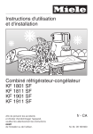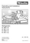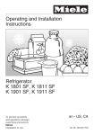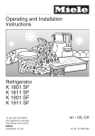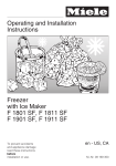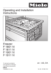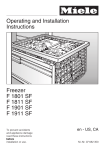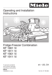
1
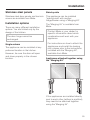
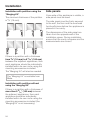
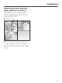
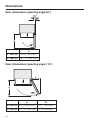
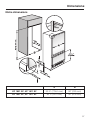
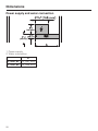
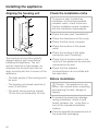
Operating and Installation
Instructions
Fridge-Freezer Combination
KF 1801 SF
KF 1811 SF
KF 1901 SF
KF 1911 SF
To prevent accidents
and appliance damage
read these instructions
before
installation or use.
en - US, CA
M.-Nr. 09 169 650
Installation instructions
Information is subject to change. Please refer to our website to obtain the most
current product specification, technical & warranty information.
To prevent accidents
and machine damage
read these instructions
before
installation or use.
49
Caring for the environment
Disposal of packing materials
Disposal of an old appliance
The cardboard box and packing
materials are biodegradable and
recyclable. Please recycle.
Old appliances contain materials that
can be recycled. Please contact your
local recycling center about the
possibility of recycling these materials.
Ensure that any plastic wrappings,
bags, etc., are disposed of safely and
kept out of the reach of babies and
young children. Danger of suffocation!
50
Before discarding an old appliance,
disconnect it from the electrical supply
and cut off the power cord to prevent it
from becoming a hazard.
Installation
Installation site
Have the appliance installed by a
qualified technician, according to
the enclosed installation instructions.
,WARNING
This appliance is top-heavy and
must be secured to prevent it from
tipping forward.
Keep the doors closed until the
appliance is completely installed
and secured as per the installation
instructions.
Empty weight of your machine:
KF 18X1 SF . . . . . . . . 511 lbs (232 kg)
KF 19X1 SF . . . . . . . . 562 lbs (255 kg)
The appliance should be installed in a
dry, well-ventilated room.
Do not install the appliance:
- outdoors
- in an environment with dripping
water
- in rooms that are at risk of frost.
The installation location should not be
exposed to direct sunlight, nor near a
heat source, such as an oven,
radiator, etc.
The ambient temperature should not
drop below 55°F (13°C) or rise above
110°F (43°C), otherwise malfunctions
may occur.
If installation next to a heat source is
unavoidable observe the following
minimum distances from the heat
source:
– 1 1/4" (3 cm) from an electric cooktop
or electric oven.
– 12" (30 cm) from a gas or oil
cooktop, range or oven.
51
Installation
Base
Ventilation
A fully loaded appliance is very heavy.
The load-bearing capacity of your floor
must meet the following requirements:
The air intake and outlet must not be
blocked or covered in any way. They
also need to be dusted/cleaned on a
regular basis.
KF 18X1 SF . . . . . . . 1,007 lbs (457 kg)
KF 19X1 SF . . . . . . . 1,250 lbs (567 kg)
To ensure that the appliance is installed
securely and functions properly, the
base must be flat, level and made of a
hard, rigid material.
If in doubt, contact Miele.
Furniture/fixtures
The new appliance will be mounted
securely to adjacent and overhead
furniture/fixtures.
For this reason, it is essential that all
attachable furniture/fixtures be
connected securely to the floor or wall
by a suitable means.
52
Installation niche
To ensure safe, trouble-free installation
and the best possible cosmetic result,
check to be sure that the installation
space complies with the installation
dimensions. See "Niche dimensions".
The side walls of the installation cavity
must be plumb.
The minimum thickness of the side
walls and the top wall must be 5/8"
(16 mm).
The minimum thickness of the toe-kick
panel must be ½" (13 mm). A thickness
of 3/4" (19 mm) is recommended.
Installation
Stainless steel panels
Side-by-side
Stainless steel door panels and toe-kick
covers are available from Miele.
This appliance can be installed
"side-by-side" with another
fridge/freezer using a "Merging Kit".
Installation options
The "Merging Kit" is available from
Miele.
There are many different installation
options. You are limited only by the
design of the kitchen.
The door hinge cannot be
exchanged.
Single column
The appliance can be installed at any
preferred location in the kitchen.
However, be sure the door will open
and close properly in the chosen
location.
Contact Miele or your dealer for
specific information about which
combinations will work with your
appliance.
For instructions on how to attach the
appliances and install the heating
mat, please refer to the instructions
included with the "Merging Kit",
available from Miele.
Appliances attached together using
the "Merging Kit"
If the appliances are installed directly
next to each other (without a partition),
they need to be attached together
using the "Merging Kit".
53
Installation
Installation with partition using the
"Merging Kit"
The minimum thickness of the partition
is 5/8" (16 mm).
Side panels
If one side of the appliance is visible, a
side panel must be used.
The side panel must be firmly secured
to the wall, the floor and the overhead
furniture/fixtures before the appliance is
placed in the cavity.
The dimensions of the side panel are
taken from the opposite wall of the
installation space. During installation,
ensure that the cavity is square and the
measurements are correct.
If there is a partition with a thickness
from 5/8" (16 mm) to 6 5/16" (160 mm)
between the adjacent appliances, then
each appliance should be individually
installed within its own niche using the
mounting accessories included.
The "Merging Kit" will also be needed.
The "Merging Kit" is available from
Miele.
Installation with partition without
using the "Merging Kit"
If there is a partition with a thickness of
more than 6 5/16" (160 mm) between
the adjacent appliances, then each
appliance should be individually
installed within its own niche using the
mounting accessories included (the
"Merging Kit" is not necessary).
54
Installation
Adjusting the door opening
angle (optional accessory)
Depending on the installation site, it
may be necessary to adjust the door
opening angle to 90°.
^ Open the door.
^ Insert the banking pin through the
holes and drive in with a hammer.
The door opening angle is now limited
to 90°.
55
Dimensions
Door dimensions (opening angle 90°)
A
KF 18X1 SF
32 5/8" (829 mm)
KF 19X1 SF
38 11/16" (982 mm)
Door dimensions (opening angle 115°)
A
KF 18X1 SF 32 5/8" (829 mm)
B
14 5/16" (363 mm)
KF 19X1 SF 38 11/16" (982 mm) 16 7/8" (428 mm)
56
Dimensions
Niche dimensions
A
B
KF 1801 SF, KF 1811 SF
30 ½" (774.6 mm)
30" (762 mm)
KF 1901 SF, KF 1911 SF
36 ½" (927 mm)
36" (915 mm)
57
Dimensions
Power supply and water connection
1. Power supply
2. Water connection
A
KF 18X1 SF 15" (381 mm)
KF 19X1 SF 18" (458 mm)
58
Installing the appliance
Before you begin
Read these instructions completely
and carefully.
Have the appliance installed by a
qualified technician, according to
the enclosed installation instructions.
To reduce the risk of injury or
damage to the product, two people
should be used for installation.
These installation instructions are
intended for use by qualified installers.
In addition to these instructions, the
appliance must be installed in
accordance with all local codes. In the
absence of a local code, the following
should be used:
– In the USA, the National Electric
Code, ANSI/NFPA 70 - latest
edition/State and Municipal codes
and/or local codes.
– In Canada, the Canadian Electric
code C22.1 - latest edition/Provincial
and Municipal codes and/or local
codes.
– Adhesive tape
– Multi-grip pliers
– Level
– Tape measure
– Square
When fastening the cabinet to the wall
behind it (see "Installing the appliance")
use:
– suitable plugs/screws depending on
the type of wall.
– several mounting brackets, if required.
Other
– Stepladder
– Dolly, hand truck
– Wooden beam (cross section
min. 3" x 4" [75 mm x 100 mm] as an
alternative tilt protection, length
depends on the width of the
installation cavity)
– Wood screws in different sizes
Optional accessories
– "Merging Kit" for side-by-side installation
Tools needed for installation
– Cordless screwdriver
– RemoteVision module for wireless
monitoring
– Torx screwdriver
– Hammer drill
– Wood drills in different sizes
– Hammer
– Rachet (5/16" / 8 mm)
59
Installing the appliance
Aligning the housing unit
Check the installation niche
To ensure a safe, trouble-free
installation and the best possible
cosmetic result, check to be sure
that the installation space complies
with the installation requirements.
^ Check the base (see "Installation").
^ Check the dimensions of the cavity.
^ Check that the cavity is square.
^ Check the location of the power
outlet.
^ Check the location of the water
connection (see "Plumbing").
The housing unit must be carefully
aligned using a spirit level before
installing the appliance. The unit
corners must be at right angles, as
otherwise the furniture door will not
align correctly with the 4 corners of the
appliance.
– The side panels of the housing must
be even.
– The housing unit panels must be at
least 16 mm thick.
– The plinth facing must be at least
13 mm thick (or preferably 19 mm).
^ Check that all furniture parts in the
vicinity of the appliance are securely
connected to the wall.
^ Check that the adjacent
furniture/fixtures do not collide with
the open door.
Before installation
,Caution - the appliance is very
heavy. Use caution when unpacking
and opening the door, danger of
tipping.
^ To protect the base from damage
during installation, attach a hard
board, linoleum, etc., to the floor in
front of the intended installation
location.
^ Take the supplied accessories out of
the protective packaging.
60
Installing the appliance
There are transportation safety
devices inside the appliance to
protect the shelves and storage
compartments until installation is
complete. Do not remove them, or
parts may be damaged.
^ Check the appliance for damage in
transit.
Do not install the appliance if it is
visibly damaged. If in doubt, contact
your dealer.
RemoteVision module
installation
(optional accessory)
Always disconnect the appliance
from the power supply when
performing installation, maintenance
or service work.
Install the RemoteVision module
before placing the appliance in its
installation niche.
Once connected the RemoteVision
module will increase the energy
consumption of the appliance.
The slot for the RemoteVision module is
located in the lower area of the back of
your appliance.
^ Loosen the bracket that holds the
appliance to the pallet.
,Caution! The appliance is no
longer secured and may be unstable.
^ From the rear of the appliance
carefully lift it from the pallet.
^ Unscrew the screws a on the cover
b and pull off the sticker c.
Once the appliance is on the ground it
can be wheeled around.
61
Installing the appliance
^ Remove the cover b.
^ Push the module into the slot until it
locks into place.
^ Connect the appliance to the power
supply and turn it on. After several
seconds the indicator light e will
come on.
The indicator light will display different
colors one after the other; any control
light at the end indicates that the
module was correctly installed.
If the indicator light does not come on,
installation of the module was
unsuccessful. In that case, repeat the
process. If that does not correct the
problem, contact Miele.
^ Pull the antenna d straight out.
^ Guide the cover b over the antenna
d and screw on the cover.
^ Angle the antenna d so that it faces
to the right or left.
If necessary, disconnect the power
supply and continue installing the
appliance.
Preparing the installation
niche
,Keep the appliance door closed
until it is securely fastened in the
niche. Tipping hazard.
Because of the size and weight of
the appliance, it is essential to
ensure that the appliance cannot tip
over once it has been mounted in
the niche.
62
Installing the appliance
Mounting Accessories
The mounting accessories needed for
installing the appliance into the niche
are included in the packaging. Several
plastic bags are included which are
numbered alphabetically.
The bag needed for each step will be
marked with its respective letter.
^ Use the included Torx screwdriver to
tighten the screws.
Anti-tip brackets
The distance "D" between the anti-tip
brackets b is the width of the
appliance.
^ Position the anti-tip brackets b on
the left and right walls of the
appliance niche.
The anti-tip brackets help keep the
appliance safely secured to the
installation niche to prevent tipping.
^ Mark the holes through the anti-tip
brackets b on the floor of the
installation niche.
Two anti-tip brackets are
recommended for each appliance or
appliance combination (side-by-side).
^ Set the brackets aside.
Screws are supplied with the
appliance for various
applications/materials.
If the anti-tip brackets cannot be
attached securely with the screws
supplied, an alternative anti-tip
device can be used.
If the installation niche is deeper than
the appliance, a solid wooden beam a
can be placed behind the anti-tip
brackets b so the appliance can be
securely attached to the base or wall.
Assure that there are no electrical
wires or plumbing in the area which
the screws could penetrate-risk of
injury and damage.
The length of the wooden beam a
should be the width of the installation
space.
63
Installing the appliance
In a cabinet with a back wall
^ Drill pilot holes:
1
–
/8" (3 mm) for 5 x 60 mm wood
screws
–
1
/16" (2 mm) for 4 x 15 mm wood
screws.
^ Tightly secure the anti-tip brackets in
the niche.
Be certain that the screws penetrate
through the flooring and into the wall
plate a minimum of 3/4" (19 mm).
^ screw the back wall of the cabinet in
several places directly to the wall
behind it.
For this, use suitable plugs/screws
depending on the type of wall.
In a cabinet without a back wall
If the included anti-tip brackets cannot
be secured in the niche, the built-in
cabinet must be secured to the wall
behind it with several screws. Only in
this way can the appliance later
secured in the built-in cabinet be
prevented from tipping.
^ screw the cabinet to the wall behind
it in several places using suitable
mounting brackets.
For this, use suitable plugs/screws
depending on the type of wall.
64
Installing the appliance
Securing an alternative anti-tip
device
– The beam must cover the appliance
by at least 2" (50.8 mm).
^ Mark the installation height (lower
edge of the beam) on the rear wall of
the niche.
^ Select screws according to the
thickness of the wooden beam.
Example: 3 ½" (89 mm) screw for 2x4
beam.
Determine the number of screws
based on the cavity width, to ensure
that the beam will be attached
securely.
^ Locate wall studs near the rear wall
of the cavity and mark drill holes in
the beam.
^ Pre-drill the wooden beam.
If the anti-tip brackets cannot be
attached securely, an alternative
anti-tip device can be used.
Ensure that there is no "give" between
the appliance and the anti-tip device.
^ Attach the wooden beam to the rear
wall of the niche.
Now prepare the water connection
from the appliance to the main
supply line (see "Plumbing").
If possible, always screw the
wooden beam to existing studs.
^ Cut a wooden beam
(cross section min. 3" x 4"
[75 mm x 100 mm]) to the required
length.
– The length is equal to the width of
the installation niche.
– If the installation niche is deeper than
the appliance, select a beam with a
larger cross section, or attach two
beams.
65
Installing the appliance
Sliding the appliance into the
installation niche
If a side-by-side installation is
desired, connect the two appliances
together. See the Installation Manual
included with the "Merging Kit".
^ Open the bottom door.
^ To protect the corners of the
installation space, attach the
supplied edge protector a on both
sides with adhesive tape.
^ To remove the stainless steel front,
loosen the two nuts and remove the
cover strip.
^ Plug the appliance into the power
outlet b.
The plug of the appliance should be
easily accessible after installation.
If the plug is not accessible after the
appliance has been installed,
disconnection from the power
supply should be completed via the
circuit breaker.
In the case of side-by-side
installations, a separate outlet must
be used for each appliance.
^ Unscrew the plinth.
66
Installing the appliance
^ To prevent the power cord from
becoming caught:
Tie a piece of string to the middle of
the power cord and feed it forward
under the appliance. When sliding
the appliance in, pull the cable
forward c.
^ Carefully slide the appliance into the
space until the height-adjustable
wheels interlock with the anti-tip
brackets d.
If resistance is felt when attempting to
slide the appliance into the installation
niche - for example, because the floor
is uneven,
^ Turn the rear adjustable wheels
slightly outward (see "Aligning the
appliance"), then push the appliance
in.
Be careful not to damage the water
pipe or power cord attached to the
floor.
^ Remove the edge protector a.
67
Installing the appliance
Aligning the appliance
^ Align the appliance with the custom
front.
^ Unscrew the height-adjustable feet
until the mark on the base has
reached the indicated guide
dimension 1 1/4" (32 mm). The guide
dimension of 1 1/4" (32 mm) is
related to a niche height of 84"
(2134 mm).
Important!
The height-adjustable feet can only
be unscrewed as far as the mark 2
3/16" (62 mm) on the base (max.
niche height of 85 3/16" (2164 mm).
The height-adjustable feet at the front
and rear can all be adjusted from the
front:
– Front feet:
Adjust with a rachet 5/16" (8 mm) e.
– Rear feet:
Adjust with a (cordless) screwdriver
and/or a rachet 5/16" (8 mm) for fine
adjustment f.
Important!
When unscrewing the
height-adjustable feet, proceed
gradually, alternating between left
and right.
^ Align the custom doors with a level.
^ If using a wooden beam as an
alternative anti-tip device, rotate the
appliance all the way toward the
wooden beam.
Note:
– The adjustment of the rear feet is
aided if the appliance is lifted at the
rear (tipped forward slightly).
68
Installing the appliance
Attaching the appliance to the
installation niche
^ Open the appliance doors.
^ Open the lower appliance door and
hand the stainless steel cover on the
double-threaded bolts.
^ Screw the nuts onto the
double-threaded bolts.
^ Replace the cover strip.
^ Fasten the appliance on the left and
right hand sides with the 3 (supplied)
wood screws.
If there is a fairly large gap above the
appliance, cut a wooden beam to fit
exactly and place it in the gap.
Now connect the water supply to the
appliance (see "Plumbing").
69
Installing the appliance
Attaching the toe-kick cover
The maximum height of the toe-kick
cover is 4" (101 mm) from the top of
the floor. Do not cover the ventilation
slits in the plinth. Risk of damage to
the appliance.
^ If required, cut the toe-kick cover to
the required length and height.
^ Remove the foil from the adhesive
strips.
^ Attach the toe-kick cover to the
plinth.
^ Attach the plinth to the appliance,
and put the included cover plates in
place.
70
Installing the appliance
Mounting the air separator
The air separator keeps the supply and
exhaust air separate. This prevents
warm exhaust air from flowing into the
machine, optimizing the energy
performance of the unit.
^ If necessary, shorten the three parts
of the air separator.
^ Insert the foam pieces back into the
sides.
^ Clip the air separator, left and right of
the partition, in the exhaust grille. Be
sure that it clicks into place and
guides the foam partition under the
exhaust grille.
71
Plumbing
All plumbing work should be carried
out by a suitably qualified and
competent person, in accordance
with all applicable local and national
regulations.
The water quality must conform to
country requirements for drinking
water.
– The appliance is only suitable for
connection to the cold water supply.
– The water pressure must be between
25 and 120 psi (1.72-8.25 bar).
– A separate shut-off valve must be
installed, so that the water supply
can be interrupted as needed.
– The maximum outer diameter of the
water pipe (without fittings):
3
/8" (10 mm).
The shut-off valve for the water
connection must not be located
behind the appliance. It is
recommended to place the shut-off
valve directly next to the appliance
(base unit) or in another easily
accessible location.
72
Plumbing
Preparing the water connection
For appliances with a hose guide
The connection to the household
water supply must be installed
before the appliance is installed.
^ Turn off the main water valve to prevent
damage caused by leaking water.
^ Attach the connecting pipe to the
shut-off valve, according to the
instructions supplied by the
manufacturer of the ice cube maker
installation kit.
^ Install the connecting pipe. Always
observe the indicated clearance
dimensions to prevent damage to the
connecting pipe when pushing in the
appliance.
^ position the device in front of the
niche and push the stainless steel
tube through the hose guide at the
back of the unit.
At this point the niche should be ready
for the appliance to be pushed back
into it (see "Installing the appliance").
^ You can now continue with the
installation.
^ Secure the connecting pipe to the
floor with adhesive tape.
^ You may now proceed to install the
appliance. See "Installing the
appliance".
73
Plumbing
Connecting the water supply
^ Push the union nut and seal onto the
water pipe.
When connecting the water pipe to
the solenoid valve of the appliance,
follow the instructions supplied by
the manufacturer of the ice cube
maker installation kit.
^ Push the end of the water pipe into
the appliance connection and screw
on the union nut, 3. First tighten by
hand.
When bending the water pipe, be sure
not to kink it, otherwise there is a risk of
leaks and water damage.
Use bending aids.
^ Then use an open-ended wrench to
tighten the union nut. Do not over
tighten.
^ Open the shut-off valve and the main
water connection. Check for leaks at
the connection for the shut-off valve
and to the appliance.
^ Switch the appliance on.
After a maximum of 10 hours the first
ice cubes will drop out of the ice
cube maker and collect in the ice
cube container.
^ Remove the cap from the appliance
connection, 1.
^ Bend the water pipe to suit the
location of the connection on the
appliance, 2.
74
Electrical connection
, Avoid the risk of electrical
shock
- Plug into a grounded 3-prong
outlet.
- Do not move the ground plug.
- Do not use an adapter.
- Do not use an extension cord.
Failure to follow these instructions
can result in death, fire, or electrical
shock.
Improper connection of the
equipment grounding conductor
may result in electric shock. If you
are in any doubt as to whether the
appliance has been properly
grounded, have the appliance
checked by a qualified electrician or
service technician.
Installation, repairs and other work
by unqualified persons could be
dangerous.
The appliance is supplied with a
UL-listed, 3-wire power cord and
NEMA 5-15 P plug ready for connection
to a 120 V, 60 Hz supply.
The fuse rating is 15 amps.
The appliance requires a 3-wire
receptacle.
The receptacle must be installed by a
licensed electrician only.
In the case of side-by-side installations,
a separate outlet must be used for each
appliance. Ideally, the power outlet
should be next to the appliance and
easily accessible. Do not connect the
appliance to the power supply by an
extension cord. Extension cords do not
guarantee the required safety of the
appliance (danger of overheating).
If any changes are needed to the
household wiring or power supply, this
work must be performed by a qualified
electrician.
Before installing the appliance,
verify that the voltage, load and
circuit rating information found on
the data plate match the household
electrical supply.
If there are any questions regarding the
electrical connection of this appliance
to the power supply, please consult a
licensed electrician or call the Miele
Technical Service.
U1-800-999-1360
V1-800-565-6435
75
Alteration rights reserved / 5011
M.-Nr. 09 169 650 / 01
INFORMATION IS SUBJECT TO CHANGE. PLEASE REFER TO OUR WEBSITE TO OBTAIN THE MOST
CURRENT PRODUCT SPECIFICATIONS, TECHNICAL & WARRANTY INFORMATION.