1
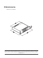
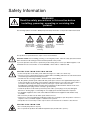
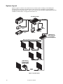
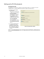
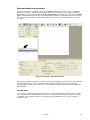
P3-100 System Controller
TM
Installation and Safety Manual
User Guide
Dimensions
All dimensions are in millimeters
©2009 Martin Professional A/S. Information subject to change without notice. Martin Professional A/S and all affiliated companies disclaim liability for
any injury, damage, direct or indirect loss, consequential or economic loss or any other loss occasioned by the use of, inability to use or reliance on the
information contained in this manual. The Martin logo, the Martin name and all other trademarks in this document pertaining to services or products by
Martin Professional A/S or its affiliates and subsidiaries are trademarks owned or licensed by Martin Professional A/S or its affiliates or subsidiaries.
P/N 35000226, Rev. A
Safety Information
WARNING!
Read the safety precautions in this section before
installing, powering, operating or servicing this
product.
The following symbols are used to identify important safety information on the product and in this manual:
Warning!
Warning!
Warning!
Safety hazard.
Refer to
Hazardous
Risk of severe manual before voltage. Risk of
injury or death.
installing,
lethal or severe
powering or
electric shock.
servicing.
Warning!
Fire hazard.
This product is for professional use only. It is not for household use.
Read this manual before installing, powering or servicing this product, follow the safety precautions listed
below and observe all warnings in this manual and printed on the product.
If you have questions about how to operate this product safely, please contact your Martin supplier or call
the Martin 24-hour service hotline on +45 8740 0000, or in the USA on 1-888-tech-180.
PROTECTION FROM ELECTRIC SHOCK
• Connect the product to AC mains power within the ranges 115 - 250 V, 47 - 63 Hz only.
• Use only a source of AC mains power that complies with local building and electrical codes and has both
overload and ground-fault (earth-fault) protection.
• The unit must be correctly grounded to electrical safety earth at all times.
• US, EU (Schuko) and UK power cables with IEC power input connectors are supplied with the product.
Connect the product to AC mains power using the cable that matches your local power outlet sockets. If
you need to replace the power plug to match any other type of power outlet socket, install a
grounding-type (earthed) listed power plug rated 5 A minimum as directed in this manual. In all cases,
check that the power plug connects correctly to ground (earth).
• Isolate the product from AC mains power if the power cable or power plug is in any way damaged,
defective or showing signs of overheating. Do not reapply power until the faulty item is replaced.
• For pluggable equipment, the socket outlet shall be installed near the equipment and shall be easily
accessible.
• Disconnect the product from AC mains power when not in use.
• There are no user-serviceable parts inside the product. Do not attempt to open the product. If service is
required, contact your Martin supplier or a Martin service partner.
• The product is for use in a dry location only. Protect it from moisture. Do not allow it to become wet.
PROTECTION FROM FIRE
• Do not modify the product in any way.
• Do not operate the product if the ambient temperature (Ta) exceeds 50° C (122° F).
• Particular attention must be paid to cooling; under no circumstances should the airflow to the heat sinks
be restricted and a rack fan cooling unit should be considered when multiple units are stacked together to
maintain the correct ambient temperature.
• The replacement fuse should be a 250 V rated 1A T (anti-surge) 20 mm cartridge type only. Never attempt
to bypass a fuse.
• Replace the internal CR2032 lithium button cell battery with one of the same type only. Risk of explosion
if battery replaced by incorrect type. Dispose of used batteries according to the manufacturer’s
instructions.
ATTENTION!
• En cas d'équipement enfichable, la prise doit être montée près de l'équipement et doit offrir un
accès facile.
• Il y a un danger d’explosion s’il y a un remplacement incorrect de batterie. Mettre au rebut les
batteries usagées conformément aux instructions du fabricant.
Contents
Dimensions . . . . . . . . . . . . . . . . . . . . . . . . . . . . . . . . . . . . . . . . . . . . . . . . . . . . . . . . . . . . . . . . . . . . . . . . 2
Safety Information . . . . . . . . . . . . . . . . . . . . . . . . . . . . . . . . . . . . . . . . . . . . . . . . . . . . . . . . . . . . . . . . . . 3
Status indicators and front panel . . . . . . . . . . . . . . . . . . . . . . . . . . . . . . . . . . . . . . . . . . . . . . . . . . . . 6
Connections panel . . . . . . . . . . . . . . . . . . . . . . . . . . . . . . . . . . . . . . . . . . . . . . . . . . . . . . . . . . . . . . . . . 7
Introduction and installation . . . . . . . . . . . . . . . . . . . . . . . . . . . . . . . . . . . . . . . . . . . . . . . . . . . . . . . . . 8
Installation . . . . . . . . . . . . . . . . . . . . . . . . . . . . . . . . . . . . . . . . . . . . . . . . . . . . . . . . . . . . . . . . . . . . . . . . 8
Connecting to power . . . . . . . . . . . . . . . . . . . . . . . . . . . . . . . . . . . . . . . . . . . . . . . . . . . . . . . . . . . . . . . . 9
System layout . . . . . . . . . . . . . . . . . . . . . . . . . . . . . . . . . . . . . . . . . . . . . . . . . . . . . . . . . . . . . . . . . . . . 10
User guide . . . . . . . . . . . . . . . . . . . . . . . . . . . . . . . . . . . . . . . . . . . . . . . . . . . . . . . . . . . . . . . . . . . . . . . . 11
Media source . . . . . . . . . . . . . . . . . . . . . . . . . . . . . . . . . . . . . . . . . . . . . . . . . . . . . . . . . . . . . . . . . . . . .
Monitor. . . . . . . . . . . . . . . . . . . . . . . . . . . . . . . . . . . . . . . . . . . . . . . . . . . . . . . . . . . . . . . . . . . . . . . . . .
Making connections and applying power. . . . . . . . . . . . . . . . . . . . . . . . . . . . . . . . . . . . . . . . . . . . . . . .
Setting up the P3-100 and panels . . . . . . . . . . . . . . . . . . . . . . . . . . . . . . . . . . . . . . . . . . . . . . . . . . . . .
Setting up video input . . . . . . . . . . . . . . . . . . . . . . . . . . . . . . . . . . . . . . . . . . . . . . . . . . . . . . . . . . . . . .
Saving presets . . . . . . . . . . . . . . . . . . . . . . . . . . . . . . . . . . . . . . . . . . . . . . . . . . . . . . . . . . . . . . . . . . . .
Remote control via DMX . . . . . . . . . . . . . . . . . . . . . . . . . . . . . . . . . . . . . . . . . . . . . . . . . . . . . . . . . . . .
Viewing live system information and the system log . . . . . . . . . . . . . . . . . . . . . . . . . . . . . . . . . . . . . . .
Managing panel utilities from the P3-100 . . . . . . . . . . . . . . . . . . . . . . . . . . . . . . . . . . . . . . . . . . . . . . .
Shutting down the system . . . . . . . . . . . . . . . . . . . . . . . . . . . . . . . . . . . . . . . . . . . . . . . . . . . . . . . . . . .
11
11
11
12
19
21
22
25
25
26
Service . . . . . . . . . . . . . . . . . . . . . . . . . . . . . . . . . . . . . . . . . . . . . . . . . . . . . . . . . . . . . . . . . . . . . . . . . . . 27
Updating and reloading P3-100 firmware . . . . . . . . . . . . . . . . . . . . . . . . . . . . . . . . . . . . . . . . . . . . . . .
Installing new LC Plus panel firmware from the P3-100 . . . . . . . . . . . . . . . . . . . . . . . . . . . . . . . . . . . .
System and hardware status information . . . . . . . . . . . . . . . . . . . . . . . . . . . . . . . . . . . . . . . . . . . . . . .
Fuse replacement . . . . . . . . . . . . . . . . . . . . . . . . . . . . . . . . . . . . . . . . . . . . . . . . . . . . . . . . . . . . . . . . .
Internal battery. . . . . . . . . . . . . . . . . . . . . . . . . . . . . . . . . . . . . . . . . . . . . . . . . . . . . . . . . . . . . . . . . . . .
Error codes . . . . . . . . . . . . . . . . . . . . . . . . . . . . . . . . . . . . . . . . . . . . . . . . . . . . . . . . . . . . . . . . . . . . . .
27
27
29
30
30
30
Troubleshooting . . . . . . . . . . . . . . . . . . . . . . . . . . . . . . . . . . . . . . . . . . . . . . . . . . . . . . . . . . . . . . . . . . . 31
Specifications . . . . . . . . . . . . . . . . . . . . . . . . . . . . . . . . . . . . . . . . . . . . . . . . . . . . . . . . . . . . . . . . . . . . . 32
Status indicators and front panel
See Figure 1. The LED status indicators and Reset button on the front panel have the following functions:
Active flashes during startup and lights
continuously during operation.
Ethernet 1 and Ethernet 2 light when
there is activity on these connectors on
the rear panel.
Digital Video In and Analog Video In
indicate the currently selected video
signal.
DMX In lights when a valid DMX signal
is present at the DMX Input connector
on the rear panel.
Output lights when the P3-100 is
sending a P3 data signal.
Overtemp lights if the P3-100 has
exceeded its maximum safe operating
temperature. A thermal protection circuit
throttles down the processor if this
happens.
Figure 1: Status indicator panel and USB ports
Reset lets you carry out a forced reset
(if the P3-100 application freezes and
you cannot reboot the processor
normally, for example). Use the tip of a
ballpoint pen to push the reset button.
The P3-100 constantly stores data in its
onboard flash memory, so you are
unlikely to lose data if the application
fails.
The two USB ports on the front panel can be used for any USB peripheral including the keyboard and mouse,
but are most conveniently placed for portable memory devices. The keyboard and mouse can be connected to
the two USB ports on the rear connections panel.
6
P3-100 user manual
Connections panel
E
D
C
F
H
J
I
G
A
B
•
A - Power input (male IEC socket)
Accepts AC mains power at 115 - 250 V,
47 - 63 Hz.
B - Fuseholder
Install a 1 A, T (time delay) fuse only.
Use the Y, C/Pb and Pr connectors for
component video. Typical connector color
coding is Green to Y, Blue to Pb and Red to
Pr.
F - DMX input (5-pin locking XLR)
For connection from a DMX controller.
C - USB ports
For mouse, keyboard, USB memory device, etc.
D - DVI-I input
For digital video input only (DVI-D).
E - Analog video inputs (BNC connectors)
RCA-to-BNC or S-video-to-RCA adapters will be
required if your analog video cable does not have
BNC connectors.
• Use the Y connector for composite video.
• Use the Y and C/Pb connectors for S-Video.
G - Ethernet port 2 – P3 output (RJ-45)
P3 signal output. Connect to the video panel
installation via an Ethernet cable.
H - Ethernet port 1 (RJ-45)
Communication with P3-100’s internal webserver
for retrieval of status information.
I - Serial data port (RS-232)
Available for future data connection options.
J - VGA monitor out (DE15)
For connection to an analog monitor (XGA
1024x768 or better).
Figure 2: Connections panel overview
Connections panel
7
Introduction and installation
This manual explains how to connect and use the Martin Professional™ P3-100™ System Controller to
display video on a Martin Professional™ LC Plus™ Series or upgraded Martin Professional™ LC™ Series
video panel installation.
For information about installing LC PLus panels, see the LC Plus user documentation supplied with panels
and available for download from the Martin website at www.martin.com
The latest firmware updates and user documentation for all Martin Professional products are always available
free of charge from the Martin website.
Warning! Read “Safety Information” on page 3 before installing, powering or operating the
P3-100.
Thank you for selecting the Martin P3-100, a video processor for the LC Plus™ Series of modular LED-based
IP65-rated video display panels from Martin Professional. This product features:
• Intuitive GUI (graphic user interface)
• DVI-I digital and composite, S-Video or component analog video input
• 500 000 pixel output resolution
• Genlock
• Image rotation
• Scaling
• De-interlacing
• Gamma curve adjustment
Comments or suggestions regarding this user manual may be e-mailed to [email protected] or posted to:
Technical Documentation
Martin Professional A/S
Olof Palmes Allé 18
DK-8200 Aarhus N
Denmark
Installation
The P3-100 System Controller is designed to be rack-mounted in a central control room for fixed installations
or flight-cased for touring applications. The 2U enclosure and 19” rack mounting complies with IEC 60297.
The unit has been qualified to operate in a dry environment within a temperature range of 0° C to 50° C
(32° F to 122° F). Do not allow it to become wet. Do not use it if the ambient temperature is outside the
specified range.
Particular attention must be paid to cooling; under no circumstances should the airflow to the heat sinks be
restricted and a rack fan cooling unit should be considered when multiple units are stacked together to
maintain the correct ambient temperature.
Before applying power to the P3-100:
• Carefully review “Safety Information” on page 3.
• Check that the local AC power voltage is within the ranges listed on the serial number label and in
“Connecting to power” below.
8
P3-100 user manual
Connecting to power
Warning! For protection from electric shock, the P3-100 must be electrically connected to ground
(earth). Power distribution circuits must be fitted with a current overload fuse or circuit breaker
and ground-fault (earth-fault) protection.
Warning! US, EU and UK power cables are supplied with the P3-100. Use only the cable that
matches your AC mains power outlet or a power cable that is listed, 16 AWG or 1.5 mm2 minimum
and power connectors that are grounding-type (earthed), listed and rated 5 A minimum.
Warning! The P3-100 does not have a power on/off switch. It is powered on as soon as mains
power is applied to the power input connector and remains powered on until mains power is shut
down at source or disconnected from the P3-100. The power socket or outlet must be located
near the P3-100 and easily accessible so that the P3-100 can easily be disconnected from power if
necessary.
Important! Connect the P3-100 and its LC Plus panel installation to the same grounded/earthed
power source to eliminate ground/earth loop problems and avoid any differences in potential that
may damage devices.
The unit is mains powered via a fused, universal input power supply unit (PSU) compatible with all worldwide
mains supply standards; 115-250 V, 47-63 Hz. To avoid differences in potential that may damage devices, it
must be connected to the same 200-240 V nominal, 50/60 Hz AC mains power outlet as the LC Plus panel
installation it is connected to. Alternatively, appropriate steps must be taken to eliminate differences in
potential at different points in the installation.
There is no power on/off switch on the P3-100. Apply and shut down power using an external switch at the
power outlet or at the main switchboard.
Avoid applying power by inserting or removing live power connectors, as this will cause arcing at the
connector contacts that may damage devices and connectors.
Installing power plugs to match local power outlets
The P3-100 is supplied with three power cables that match US, European (Schuko) and UK mains power
sockets.
If these cables are not suitable, you will need to obtain a grounding-type (earthed) power cable rated 5 A
minimum with an IEC connector and a power plug that matches your local AC mains power outlet sockets.
Cables of this type are easy to obtain from computer hardware suppliers for example. Alternatively, you can
replace the power plug on one of the supplied power cables with a power plug of your local standard type. If
you do this, install a grounding-type (earthed) plug that is rated 5 A minimum and follow the plug
manufacturer’s instructions. Table 1 shows common wire color codes and pin identification symbols. If pins
are not clearly identified, or if you have any doubts about proper installation, consult a qualified electrician.
Wire color
(US color code)
Wire color
(EU color code)
Pin
Symbol
Screw (US)
black
brown
live
L
yellow or brass
white
blue
neutral
N
silver
green
yellow/green
ground
(earth)
green
Table 1: Wire colors and pin identification
Important! Do not shut down or disconnect power during a firmware update or while saving a
configuration file, as this will cause corruption of data that may make the P3-100 inoperable.
Use the Shutdown button and allow the P3-100 software to close down before cutting power to
the P3-100.
Introduction and installation
9
System layout
Figure 3 is given for reference only and shows how an entire system consisting of a P3-100 System
Controller and LC Plus panels should be laid out and connected. For full details of panel installation –
including important safety information – refer to the LC Plus user documentation supplied with panels and
available for download free of charge from www.martin.com
P3-100 Controller
P3 signal
DVI
Analog
video
Mouse
Analog
video
Keyboard
Monitor
1GB Ethernet
switch required
if installation
exceeds 50 panels
Max. 50 panels per daisy-chain
1GB Ethernet
switch required
if cable length
exceeds 100 m
100 m
cable
Figure 3: System layout
10
P3-100 user manual
User guide
Before operating the P3-100, read “Safety Information” on page 3 of this guide and read the Safety and
Installation Guide supplied with the LC Plus panels.
The first part of this section assumes that you have a P3-100 controller, media source and monitor, and that
the P3-100 is connected to an LC Plus panel installation. However, the P3-100 system is designed to also let
you prepare a video display and installation configuration while working offline, then quickly adjust the
installation to match your prepared work when you connect to the installation (see “Service” on page 27).
Media source
As a media source, we recommend the use of a product from the Martin Maxedia™ series. Maxedia products
offer fast processors, advanced features, DVI output and an intuitive user interface.
Besides a Maxedia media server/processor, any DVD player, video camera or other analog video source with
an S-video, composite video or component video output can be used as a media source.
Monitor
The P3-100 has EDID functionality and automatically adapts monitor resolution to fit the monitor connected to
it. It accepts 1024x768, 1280x1024 and 1600x1200 monitors.
If no monitor is connected or the connected monitor cannot be recognized, the P3-100 defaults to 1024x768.
Making connections and applying power
1. Check that the LC Plus panel installation has been safely connected. See Figure 3 for a system layout
diagram.
2. See Figure 2 on page 7. On the P3-100’s rear panel:
- Connect the Ethernet data cable from the LC Plus panels to Ethernet port 2 (G). Note that Ethernet port
1 (H) is available for future data connection options only and cannot send a P3 signal to LC Plus panels.
- Connect a monitor to the VGA monitor port (I).
- Connect a mouse and keyboard to two of the USB ports.
- Connect either a DVI-D video source to the DVI-I port or an analog video source to the analog video
BNC connectors (using RCA phono-to-BNC adapters if necessary).
3. Connect the P3-100 System Controller and LC Plus panels to the same power outlet. The power outlet
must be grounding-type/earthed. Martin Professional cannot be held responsible for any damage caused
if devices are not connected to AC mains power and ground/earth as specified in this guide. Apply power
to the panels and any Ethernet switches used.
4. The P3-100 does not have a power on/off switch. It starts up as soon as power is applied to its power
cable. At startup the P3-100 boots using the software stored in its internal flash memory.
See Figure 4. Before powering off the P3-100, always use the Shutdown button
in the top-right corner of the monitor to shut down the system.
Figure 4: Shutdown
button
User guide
11
Setting up the P3-100 and panels
Configuration files
Configuration files contain all the configuration settings and data related to your installation. The active
configuration file is constantly updated and saved in the P3-100’s internal flash memory.
1. See Figure 5. Open the File
menu and either:
- Select the most recently used
configuration file from the list at
the top of the Recent
Configurations window (this
file is called test in Figure 5).
- Select Browse to look for a
configuration file either in the
P3-100’s internal flash memory
or on a removable USB
memory storage device.
- Select Create New to create a
new configuration file and save
it in the P3-100’s internal flash
memory.
2. If you want a portable backup of
a configuration file you have
saved in the P3-100’s internal
flash memory, you can copy the
file to a USB memory device at
any time using the Save Copy
command.
Figure 5: File Operations window
If there is no user input within the first 10 seconds after booting, the P3-100 loads the configuration file from
the top of the Recent Configurations list (i.e. the configuration file that was active when the P3-100 was last
shut down).
12
P3-100 user manual
Recommended setup procedure
See Figure 6. When the configuration file loads, the Setup window opens. If any LC Plus or upgraded LC
panels are connected to the P3-100, it auto-detects them, retrieves data from them, and lists each panel’s
display address, type and serial number under Discovered Devices (arrowed) on the lower left of the Setup
window. Note that detected panels may have identical display addresses, depending on where panels were
last used. We recommend that you ignore this problem for the moment – it can be fixed later in the setup
procedure.
Figure 6: Panel Setup – Discovered Devices
If panels have been detected, there is nothing to stop you positioning them in the video frame and configuring
them immediately, but if you are not familiar with the P3-100 we recommend you follow the two-stage
procedure below, in which you first set up an on-screen ‘virtual installation’ and then map detected panels to
that installation.
Working offline
You can set up complete configurations and save presets and configuration files offline (i.e. with no panels
are connected to the P3-100) to familiarize the system or to prepare a video display in advance of an event,
for example. You will need to follow the two-stage approach described below if you want to configure an
installation offline.
User guide
13
Stage 1: Setting up the on-screen ‘virtual installation’
1. Prepare a plan of what panels the physical installation will contain and
where those panels will be located.
2. See Figure 7. Check that Next number (arrowed) is set to 1.
Figure 7: Next number
3. See Figure 8. Click on the panel
type in the Fixture Library
(arrowed) that corresponds to the
panel you want to place in position
number 1 in the installation.
4. The white square on the right of
the screen corresponds to the
video frame the P3-100 is set to
display. Move the cursor over this
area. The cursor will take the form
of a panel. Click to approximately
position panel number 1 on the
video frame.
5. See Figure 8. The panel will be
placed on the video frame in your
on-screen installation labelled with
display address 1 in the center of
the panel icon. The panel will also
appear with an orange
‘bullet-point’ in the Configured
Devices list. The number in the
Next number box will jump to 2,
ready for the next panel.
Figure 8: Fixture Library
If the P3-100 has auto-detected panels that are connected to it and these panels have the same display
address as the panels you add to the on-screen installation, they will automatically be assigned to the
panels in your on-screen installation and appear in the Configured Devices list with a green bullet-point.
Ignore this for the moment: you will assign physical panels to the on-screen installation later.
See Figure 9. Multi-mode is active by default. In this mode, you simply click on
the video frame each time you want to position another panel (if you de-activate
Multi-mode, you must click on the desired panel type in the Fixture Library
each time you want to add a panel to your on-screen installation).
Figure 9: Multi-mode
active
6. Continue adding panels, selecting a different panel type in the Fixture Library if necessary. To remove a
panel from the on-screen installation, right-click on it and select Delete.
7. When you have added the correct number and type of panels to your on-screen installation, click on the
currently selected panel type in the Fixture Library to deselect it and stop adding panels. Your virtual
14
P3-100 user manual
installation should now look something like the example in Figure 10 that contains four LC+ 2140 panels.
Panel 1 is red in Figure 10 because it has been selected by clicking on it.
Figure 10: An on-screen virtual installation with 4 panels
8. See Figure 11. If necessary, use the Magnification tools to adjust
the magnification of the video frame on the right of your monitor
screen until you have a comfortable size to work with.
Figure 11: Magnification tools
User guide
15
9. You can now adjust the position of on-screen panels until the panel layout in your ‘virtual’ installation
exactly matches the layout in the physical installation:
- See Figure 12. Activate or deactivate Snap to Grid (arrowed) to
make it easier to position panels in alignment.
- If you drag panels with the mouse, they will ‘glue’ together if you
move them within a few pixels of each other.
Figure 12: Snap to Grid
- If you click on a panel in the video frame to
select it, it turns red. You can select multiple
panels using Shift + click or Ctrl + click.
- You can adjust the position in the video
frame of selected panels pixel by pixel using
the arrow keys on the keyboard or the x and
y coordinates under Positioning.
- You can rotate selected panels in 90° steps
under Positioning. See Figure 13. A black
square (arrowed) in the corner of each panel
indicates its top-left corner. This is a useful
reminder that you have rotated a panel.
Figure 13: Panel numbers in Setup
If no LC Plus panels are connected to the P3-100 but a video source is connected, go to “Setting up video
input” on page 19 to continue preparing the installation offline, then return to the section below when you
connect panels. If panels are connected to the P3-100, continue below.
Stage 2: Assigning physical panels to the on-screen installation
The P3-100 auto-detects LC Plus panels that are powered on and connected to it. Panels keep their display
addresses in memory when powered off, so depending on how a detected panel was set up the last time it
was installed, its display address may be wrong, or more than one panel may have the same display address.
Your first task is therefore to set the detected panels’ display addresses correctly so that each panel will
display the correct portion of the video image.
1. See Figure 14. If any panels are listed under Configured Devices, click on the plus symbol next to each
panel so that you can see each panel’s serial number (arrowed), then click on each panel’s serial number
to select that physical panel. Each time you select a physical panel’s serial number, its Device
Properties will appear at the bottom of the Setup window.
2. See Figure 14. For each panel, first set it to display a test pattern under Device Settings (arrowed), then
look at the physical installation to see which panel is displaying the test pattern. Check that this panel has
the correct display address for its position in the installation with reference to your plan of the installation
layout or the panel numbers in your on-screen ‘virtual’ installation. If the panel’s display address is not
correct, enter its correct display address in the Number box under Device Properties. The panel’s
16
P3-100 user manual
display address should now be correctly matched to its position in the physical installation. De-activate the
test pattern for that panel and continue checking any remaining panels.
Figure 14: Device Properties for Discovered Devices
Note! Physical panels in the installation must have the correct display address for their position in
the physical installation. You cannot give a panel a correct address by moving it with the mouse to a
new location in the on-screen installation – doing this will not change the display address of the
panel, it will simply move the part of the video image displayed by that panel to the wrong position in
the physical installation. If a physical panel has an incorrect display address for its position in the
installation, you must either (a) enter Device Properties for that panel and set its display address to
the correct number as described above, or (b) manually set the correct display address for that panel
using the control buttons on the back of the panel base.
3. Once you have given correct display addresses to panels in the Configured Devices window, repeat this
process for any panels in the Discovered Devices list. See Figure 15. Click on the panel name (arrowed)
to open its Device Properties, set the panel to display a test pattern (arrowed), give the panel the correct
display address (arrowed) for its position in the physical display, then de-activate the test pattern. Each
time you give a correct display address to a detected panel, it will appear in the Configured Devices list
User guide
17
with a green bullet-point to show that the detected physical panel has been configured and is assigned to
a panel in the on-screen installation.
Figure 15: Device Properties for Discovered Devices
4. See Figure 16. When you have finished
addressing panels, click on the test pattern
button (arrowed) in the toolbar at the top of
the screen to activate a test pattern over the
whole installation. Select Panel Num from
the scroll-down list of pattern types beside
the button. The LC Plus panels in the
installation will now show their display
addresses as large numbers. An arrow will
indicate their up/down orientation, and angles
will indicate panel corners.
5. Check that display addresses are correct. If
you have made a mistake during addressing,
go back and adjust any incorrect display
addresses as described earlier until the
installation is correctly laid out.
Figure 16: Test pattern
6. Deactivate the whole-installation test pattern. The on-screen installation now matches the physical
installation, and you are ready to set up the video input.
18
P3-100 user manual
Setting up video input
The P3-100 accepts digital (DVD-D) video at up to 1280 x 1024 resolution as well as analog composite,
S-video and component video using PAL, NTSC and SECAM systems.
To use the largest DVI-D resolutions, you may need to either crop the input using the Video Viewport
settings or scale the input using the Video Scaling feature. The maximum reduction factor for video scaling is
8, so you can shrink the video image to one eighth of the original resolution.
Configuring EDID settings for a digital video source
If using a digital video source, you must adjust video input resolution and EDID settings before connecting (or
before powering up) the media server or video source:
1. Open the Video Input
window.
2. See Figure 17. The
Resolution box indicates
the current video input
resolution. This must
match the resolution of the
incoming video signal.
Adjust if necessary.
3. Click on the EDID button to
open the Configure EDID
pop-up window. The
checkboxes for resolution
Figure 17: Video input resolution and EDID settings
and refresh rate here
determine the EDID
information communicated to a graphics card in a media server or PC:
- You can force a media server to supply video in one resolution and at one refresh rate if you check only
that resolution and refresh rate in the Configure EDID window.
- If you check several resolutions and refresh rates, the media server will supply video at the lowest
resolution and slowest refresh rate by default.
User guide
19
4. See Figure 18. Open the Video Input window. Select your video source type under Video Input
(arrowed).
5. Depending on your video source type, make the following selections:
- If using a DVI digital source, select your source video resolution.
- If using an analog source, select your system: PAL, NTSC or SECAM (these radio buttons are not
shown in Figure 18 but are visible if you select Component, S-Video or Composite under Video
Source).
Figure 18: Video input window
6. Adjust the size and position of the portion of the video frame you want to work with under Video
Viewport. If you want to work with the full, uncropped video frame, click on the 1:1 button.
7. Adjust the scaling of the video frame under Video Scaling, locking the aspect ratio and selecting 4:3 or
16:9 ratio if required. The more you scale down the video frame, the more of the frame you can display on
an array of LC panels and the greater the degree of pixellation as the P3-100 resamples the video image.
You can scale down to a maximum reduction factor of 8.
8. If necessary, use the Magnification tools (see Figure 11 on page 15) to adjust the magnification of the
video frame on the right of your monitor screen until you have a comfortable size to work with.
9. See Figure 19. Use the View buttons to choose whether you want to see the
whole video frame, the frame with panels overlaid, or only the part of the frame
displayed on your panels.
Figure 19: View
buttons
Frame synchronization to an analog signal
To synchronize the frame processing of digital video input with an analog video source:
1. Check the Sync to analog checkbox under Video Input for a DVI-D source and select the analog source
type and system.
2. Connect an analog video signal to the analog video input connector(s).
20
P3-100 user manual
Adjusting the video image
1. See Figure 18. Open the Video Input window.
2. Adjust brightness, contrast, gain, etc. of the video image in real-time by moving the corresponding sliders.
The image adjustments available depend on the type of video source you have selected.
Adjusting brightness and gamma curve of the installation
1. See Figure 18. In Panel Settings in the Video Input window you can adjust the brightness of the entire
installation using the Screen Brightness slider.
2. Under Gamma you can select a preset gamma curve or click on Edit to open the Gamma Curve Editor
(see Figure 20) where you can fine-tune the gamma curve of your display.
3. If you click on New and enter a name for any gamma curve you edit, it will be saved as a preset gamma
curve when you click on the Close button.
4. With the Link RGB checkbox (arrowed) checked, you can adjust the gamma curve for all three colors
together. If you uncheck the Link RGB checkbox, you can adjust the gamma curve separately for each
color.
Figure 20: Gamma curve editor
Saving presets
See Figure 21. At the bottom of the Video Input window is a list of presets that allow you to recall
configuration data:
1. Click on a floppy disk icon next to a preset name to save the current Setup and Video Input configuration
to that preset.
2. If you wish, rename a preset by clicking in its text field and entering a personalized name.
User guide
21
3. Click on the green arrows to recall presets.
Figure 21: Presets
Note that presets recall both Setup and Video Input configuration data but not Remote Control data.
Remote control via DMX
You can freeze, blackout, adjust overall and individual color intensities or move the video image on the panels
in your installation by sending DMX values from a DMX controller connected to the P3-100.
In the P3-100 interface, DMX commands are set up to control parameters of the video display on LC PLus
panels using Controls and Variables:
• Controls are functions that contain DMX channel and setup options.
• Variables are functions that contain panel display options.
Any Control can be set to control any Variable or to control multiple Variables.
Setting up Controls
To set up a Control, open the Remote Control window (see Figure 22). Controls appear on the left of the
window. You can create new Controls using the Add Control button (arrowed), and you can edit the names
of your Controls. You can delete a Control by clicking on its button, and you can expand and collapse the
setup details of each Control using its
button.
Figure 22: Remote Control window
22
P3-100 user manual
To set up a Control function:
1. Use the Add Control button to create a new Control.
2. Select the DMX channel you want to use to control parameters in the display. This channel will give you
8-bit control.
3. If you want to use 16-bit fine control, check the 16-bit Control checkbox and specify which High DMX
Channel you want to use for fine control.
4. Enter minimum and maximum values under Range if you want to define the range of DMX values that will
be used to control the variable. Values from 0 to 255 can be defined for 8-bit control and from 0 to 65535
for 16-bit control.
Setting up Variables
The Variables you can control via DMX using a Control in the P3-100 interface appear on the right of the
Remote Control window. You can create new Variables using the Add Variable button to the right of the
Add Control button, and you can edit the names of your Variables. You can delete a Variable by clicking on
button, and you can expand and collapse the setup details of each Variable using its
button.
its
Pre-programmed Variables
The first two Variables are pre-programmed and cannot be deleted. They should both be set up as non-fade
(snap) controls on the DMX controller.
• The first Variable allows you to Freeze the video image, Blackout the entire installation and display Test
patterns on the entire installation. Selecting Live Input lets you return from any of these three modes to
normal video playback.
• The second Variable, Capture Properties, calls up any configuration presets saved under Presets at the
bottom of the Video Setup window.
To assign a Control to one of the two pre-programmed Variables, select it from the drop-down list for that
Variable. The DMX channel (or channels in 16-bit mode) and other settings are now linked to that variable.
Custom Variables
You can create two types of custom variable:
Picture Variables (see arrow in Figure 23) let you use DMX commands to control the overall intensity and/or
individual color intensities of one or more panels.
Figure 23: Picture variable
Position Variables let you use DMX commands to control the x-y coordinates of panels in the video frame. In
other words they let you move the portion of the video image you display on panels from a DMX controller.
Setting up a Picture Variable
1. Use the Add Variable button at the top of the Remote Control window to create a new variable. If it is the
first custom variable you create it will have the name Variable 3 by default, but you can rename it in the
Name box.
User guide
23
2. Define the percentage range of intensity adjustment for Negative and Positive under Offset Range.
3. Use the Control drop-down list to select the Control from the left of the window that you want to use to
control the variable. If you have entered customized names for your Control functions, those names will
appear in this drop-down list.
4. You must now define which panels the new Variable should apply to, and which intensity parameters it
should control. Open the Setup window and click on a panel in your installation to select it. Use Shift +
click to add panels to your selection.
5. When you have selected the panels you want to control with the Variable, look at the Colour Correction
box at the bottom of the Setup window (see Figure 24). Here you can select the Variable in the
drop-down lists (arrowed) to assign it to control any combination of overall intensity and individual RGB
color intensities.
Figure 24: Assigning a Picture variable in the Setup window
In Figure 24, only the panel with display number 1 in the installation, an LC 2140+ Model, has been
selected, so the Variable will only be applied to this panel. Variable 3 has been selected for Intensity and
No Variable selected for RGB intensities, so Variable 3 will control the overall intensity of panel 1.
Setting up a Position Variable
1. Create a new variable as described above, but select Position as the Type (see arrow in Figure 23).
2. The Negative and Positive values you can set for Offset Range are now expressed as numbers of pixels
instead of percentages. Enter values here for the number of pixels you want to be able to move the video
display using DMX.
3. Use the Control drop-down list to select the Control from the left of the window that you want to use to
control the variable. If you have entered customized names for your Control functions, those names will
appear in this drop-down list.
24
P3-100 user manual
4. You must now define which panels the
new Position Variable should apply to,
and whether it should move panels along
the x axis, y axis or both x and y axes
relative to the video image. Open the
Setup window and click on a panel in your
installation to select it. Use Shift + click
to add panels to your selection.
5. When you have selected the panels you
want to control with the Position
Variable, look at the Positioning box at
the bottom of the Setup window (see
Figure 25). Here you can select the
Position Variable in the drop-down lists
(arrowed) to assign it to control x and/or y
axis positioning.
In Figure 25, panels 1 - 4 have been
selected, so the Variable will be applied
to these panels. Variable 3 has been
selected for both x and y axes, so
Variable 3 will move panels 1 - 4
diagonally relative to the video image.
Note that if panels are moved up relative
to the video image, the image will appear
to move down when you view the
installation.
Figure 25: Custom Position variable in Setup window
Viewing live system information and the system log
1. See Figure 26. Open the Live window and select Info under Log Level (arrowed). The P3-100 keeps a
running log of system events that can be very useful during troubleshooting.
Figure 26: Live window
Managing panel utilities from the P3-100
You can manage two LC Plus and one standard LC panel utilities remotely from the P3-100.
Display Control
Display Control lets you activate or de-activate the status LEDs and onboard control panel display in the
base of LC Plus panels (as well as LC panels that have been upgraded to LC Plus). If you want your
installation to be totally dark when video is blacked out, select the panels in the Setup window and then set
Display Control to Off to black out the base of each panel.
User guide
25
Fan control LC
In standard LC series panels that have been upgraded to LC Plus, you can set cooling fan operation to On,
Off and Auto from the P3-100. Select panels in the Setup window first, then select the fan control option you
want to apply to them.
Keyboard shortcuts
The following keyboard shortcuts are available when working with panel layout:
Function
Shortcut
View hardware settings dialog box
Ctrl + S
Zoom in/out
Ctrl +; Ctrl + <mouse wheel>
Vertical scroll
<mouse wheel>
Horizontal scroll
Alt + <mouse wheel>
Select all
Ctrl + A
Hand scroll mode
H
Stop adding panels in multi-mode
Esc
Additive selection
Ctrl + click
No snap to grid and snap to panel while dragging
Alt + <mouse drag>
Fine move with arrow keys when snap to grid active
Alt + <arrow key>
Coarse move with arrow keys when snap to grid off
Alt + <arrow key>
Table 2: Keyboard shortcuts
Shutting down the system
To shut down the P3-100 System Controller safely:
1. Use Save Copy in the File window to create any backups you might want to store on the USB memory
device.
2. Click on the Shutdown button at the top right of the screen (see Figure 4 on page 11). When the P3-100
displays a message telling you that it is safe to shut down the system, cut power to the P3-100.
26
P3-100 user manual
Service
There are no user-serviceable parts inside the P3-100 System Controller. Do not open any cover or attempt
to modify or repair the unit. Doing so will void the product warranty. Refer all service to Martin Professional or
its authorized service agents.
Important! Do not shut down or disconnect power while updating firmware in the P3-100 or LC
Plus panels, as this will corrupt the data and may make the P3-100 inoperable.
If you update the P3-100 System Controller firmware, update the firmware in all the connected LC
Plus panels to ensure full compatibility between controller and panel firmware.
Updating and reloading P3-100 firmware
The P3-100 System Controller firmware can be reloaded – overwriting
the existing firmware – if an update becomes available or if you
suspect that the firmware has become corrupted. The firmware is
available for download free of charge from the Martin website at
www.martin.com. Files use a p3-100sc-XXX.fw naming convention in
which XXX is the version number.
Figure 27: Hardware Settings
button
To reload the P3-100 System Controller firmware:
1. Connect a USB memory device loaded with the P3-100 System Controller firmware to any of the P3-100’s
USB ports.
2. See Figure 27. Click on the
Hardware Settings button
(arrowed).
3. See Figure 28. The current
firmware version is displayed in the
Firmware panel (arrowed). Click
on the Reload Firmware button
and browse to the
p3-100sc-XXX.fw file on the USB
memory device. Click on Open and
wait while data is copied.
4. If the file is copied successfully, a
dialog box opens asking you to
restart the P3-100. Click on OK
and wait while the P3-100 reboots
on the new firmware. If the new
firmware is corrupted or incorrect,
the P3-100 will return to the last
valid firmware.
Figure 28: Firmware version and reloading firmware
5. If the P3-100 firmware update is
successful, update the firmware in the LC panels as described below.
Installing new LC Plus panel firmware from the P3-100
Install new firmware in the LC Plus panels each time you update the firmware in the P3-100 System
Controller, or if you suspect that a panel has a software-related fault. The LC Plus panel firmware is
integrated in the P3-100 System Controller firmware file.
Service
27
Updating firmware in one panel
To install new LC Plus panel firmware in a selected panel:
1. In the P3-100 application, open the Setup window (see Figure 14 on page 17). The Configured Devices
list on the left of the screen lists the LC Plus panels that are connected and configured. Each panel has a
line in the list consisting of a plus sign, green button and panel type. Click on the plus sign to view the
panel’s serial number.
2. Click on the panel’s serial number to open Device Properties for that panel at the bottom of the screen.
3. Click on the Reload Firmware button at the bottom of the Device Properties and follow the instructions
on the monitor screen.
4. Finally, de-select the panel in the Configured Devices list.
Updating firmware in multiple panels
See Figure 29. If you connect to panels that are running outdated firmware, the P3-100 may show a warning
and ask whether it should automatically update those panels with the latest firmware.
If you allow the P3-100 to update the panels, it will automatically update only the panels that have an older
version of the panel firmware. The P3-100 displays a list of panels and shows update status during the
reload.
Figure 29: Updating firmware in multiple panels
28
P3-100 user manual
System and hardware status information
Viewing directly on the monitor
To view system and hardware status
information on the monitor:
1. See Figure 27. Click on the Hardware
Settings button (arrowed).
2. See Figure 28. Click on the blue question
mark button in the bottom left of the
Hardware Settings window.
3. See Figure 30. The P3-100’s firmware
version, serial number, uptime (resets at
power on) and hardware temperatures are
displayed in a pop-up window.
Figure 30: System and hardware info
Remote viewing via
network
The P3-100 also features a
built-in webserver that allows
remote access to status
information via a network.
To access status info over a
network:
1. Plug a network cable into
Ethernet port 1 on the
P3-100’s rear panel to
connect the P3-100 to the
network.
2. See Figure 27 on page 27.
Click on the Hardware
Settings button (arrowed).
3. See Figure 28 on page 27. If
using DHCP, make sure the
Use DHCP checkbox under
Network Settings is
checked. Otherwise enter
static IP address, subnet
mask and gateway details.
4. Start a web browser on a
PC on the network and open
the address http:// followed
by the IP address shown
under Web Server in the
Hardware Settings window.
This connects you to the
P3-100 and opens a
webpage containing status
information for the P3-100
and all connected panels
(see Figure 31).
Figure 31: System info via network
Service
29
Fuse replacement
Warning! Disconnect the power cable before opening the fuseholder. Replace the fuse with one of
the same type and rating only.
The main fuse is located in a fuseholder (B in Figure 2 on page 7) next to the mains power inlet socket.
To replace a fuse:
1. Shut down power and disconnect the power cable.
2. Use a flat-bladed screwdriver to open the fuseholder.
3. Remove and test the main fuse. If it has blown, replace it with a 250 V-rated, 1 A, T (slow-blow) 20 mm
cartridge-type fuse only.
4. Reinstall the fuseholder and reconnect the power cable.
Internal battery
Warning! Risk of explosion if battery replaced by incorrect type. Refer to Martin Professional for
battery replacement.
The unit’s internal real-time clocks are battery-backed to ensure operation when the unit is not powered. The
batteries should last for at least 10 years and are easily replaced when necessary, replacement battery:
Renata CR2032 Lithium Button Cell. If you suspect that the internal batteries are no longer serviceable,
contact Martin Professional for replacement.
Error codes
In the event of a system error, the LEDs on the front panel indicate error codes by a repeating pattern of
flashing the LEDs a number of times in succession, followed by a 1 second pause.
Main board errors are indicated by the bottom four LEDs only flashing as follows:
• 2 flashes - Failed to power up main board
• 3 flashes - Firmware failed to boot
• 4 flashes - Power failed during boot
• 5 flashes - Power failed during normal operation
• 6 flashes - Watchdog timeout expired
Front panel errors are indicated by all LEDs flashing as follows:
• 1 flash - Invalid build version.
• 2 flashes - Unable to determine serial number.
• 3 flashes - SPI flash test failed.
• 4 flashes - Unable to perform front panel factory restore as factory firmware is corrupt.
• 5 flashes - Current front panel firmware is corrupt and there are no valid firmware versions available to
restore.
• 6 flashes - Restored front panel firmware is corrupt.
Front panel errors 1-3 may be generated by the bootloader or the main front panel firmware. Errors 4-6 may
only be generated by the bootloader.
30
P3-100 user manual
Troubleshooting
Problem
P3-100 is completely dead.
One or more panels displays
video incorrectly or does not
display video at all.
All LCP panels and/or monitor
screen display video incorrectly
or do not display video at all.
P3-100 cuts out.
Probable cause(s)
Remedy
No power to unit.
Check power and connections.
Fuse blown (located next to power input
connector).
Disconnect power cable. Check fuse and replace.
Fault on P3 link.
Inspect connections and cables. Correct poor
connections. Repair or replace damaged cables.
Incorrect panel addressing.
Check addressing setup in P3-100 System
Controller.
Panel defective.
Have faulty panel serviced by Martin service
technician.
Other device (e.g. Ethernet switch) on P3 link
defective.
Replace with a device known to be operating
correctly. Have faulty device tested and serviced.
Unusable video signal or defective video
source.
Check video source.
Fault on P3 link.
Inspect connections and cables. Correct poor
connections. Repair or replace damaged cables.
Device on P3 link defective.
Replace with a device known to be operating
correctly. Have faulty device tested and serviced.
Unit is too hot.
Ensure free airflow around unit.
Clean heatsinks on front and rear panels.
Check that ambient temperature does not exceed
max. permitted level.
Contact Martin for service.
Table 3: Troubleshooting
Troubleshooting
31
Specifications
Physical
Width . . . . . . . . . . . . . . . . . . . . . . . . . . . . . . . . . . . . . . . . . . . . . . . . . . . . . . . . . . . . . . . . . . 482 mm (19 in.)
Depth . . . . . . . . . . . . . . . . . . . . . . . . . . . . . . . . . . . . . . . . . . . . . . . . . . . . . . . . . . . . . . . . . . 380 mm (15 in.)
Height (rackmount 2U). . . . . . . . . . . . . . . . . . . . . . . . . . . . . . . . . . . . . . . . . . . . . . . . . . . . . .90 mm (3.6 in.)
Weight . . . . . . . . . . . . . . . . . . . . . . . . . . . . . . . . . . . . . . . . . . . . . . . . . . . . . . . . . . . . . . . . . . 7.7 kg (17 lbs.)
Control/User Interface
User interface. . . . . . . . . . . . . . . . . . . . . . . . . . . . . SXGA (1280x1024) or better monitor, keyboard, mouse
Status. . . . . . . . . . . . . . . . . . . . . . . . . . . . . . . . . . . . . . . . . . . . . . . . . . . . . . . . . . . . . Status indicator LEDs
DMX512 control . . . . . . . . . Intensity, RGB, video image position, freeze frame, blackout and test patterns
Video Processing
Processor capacity . . . . . . . . . . . . . . . . . . . . . . . . . . . . . . . . . . . . . 500 000 pixels (400 LCP 2140 panels)
Output resolution . . . . . . . . . . . . . . . . . . . . . . . . . . . . . . . . . . . . . . . . . . . . . . . . .Any within 500 K pixel limit
Total system latency (worst case) . . . . . . . . . . . . . . . . . . . . . . . . . . . . . . . . . . . . . . . . . Less than 3 frames
DVI video input. . . . . . . . . . . . . . . . . . . . . . . . . . . . . . . . . . . . . . . . . . . . . . Up to 1280 x 1024, 50/60/75 Hz
Analog video input . . . . . . . . . . . . . . . . . . . . Composite, component and S-video, PAL, NTSC and SECAM
Frame synchronization to analog signal . . . . . . . . . . . . . . . . . . . . . . . . . . . . . . . . . . . . . . . . . . . . . . . . . Yes
Image rotation . . . . . . . . . . . . . . . . . . . . . . . . . . . . . . . . . . . . . . . . . . . . . . . . . . . . . . . . . . . . . . . . . . . . . Yes
Scaling . . . . . . . . . . . . . . . . . . . . . . . . . . . . . . . . . . . . . . . . . . . . . . . . . . . . . . . . . . . . . . . . . . . . . . . . . . . Yes
De-interlacing. . . . . . . . . . . . . . . . . . . . . . . . . . . . . . . . . . . . . . . . . . . . . . . . . . . . . . . . . . . . . . . . . . . . . . Yes
Gamma curve selection and adjustment . . . . . . . . . . . . . . . . . . . . . . . . . . . . . . . . . . . . . . . . . . . . . . . . . Yes
Real-time panel content remapping. . . . . . . . . . . . . . . . . . . . . . . . . . . . . . . . . . . . . . . . . . . . . . . . . . . . . Yes
P3 Signal Protocol
Signal type . . . . . . . . . . . . . . . . . . . . . . . . . . . . . . . . . . . . . . . . . . . . . . . . . . . . . . . . . . . . . .Gigabit Ethernet
Protocol . . . . . . . . . . . . . . . . . . . . . . . . . . . . . . . . . . . . . . . . . . . . . . . . . . . . . . . . . . . .Proprietary Martin P3
Hot pluggable. . . . . . . . . . . . . . . . . . . . . . . . . . . . . . . . . . . . . . . Yes, electrically isolated at all connections
Cable type . . . . . . . . . . . . . . . . . . . . . . . . . . . . . . . . . . . . . . . . . . . . . . . . . . . . . . . . . . . . . . . . . . . . . CAT 5e
Cable length. . . . . . . . . . . . Up to 100 m (328 ft.) between any 2 devices, extendable with Ethernet switch
Max. number of panels per chain. . . . . . . . . . . . . . . . . . . . . . . . . . . . . .50, extendable with Ethernet switch
Latency between first and last panel . . . . . . . . . . . . . . . . . . . . . . . . . . . . . . . . . . . . . . . . . . . . . . . . . . None
Construction
Housing . . . . . . . . . . . . . . . . . . . . . . . . . . . . . . . . . . . . . . . . . . . . . . . . . . . . . . . . . . . . . . . . Steel, aluminum
Color . . . . . . . . . . . . . . . . . . . . . . . . . . . . . . . . . . . . . . . . . . . . . . . . . . . . . . . . . . . . . . . . . . . . . . .Matt black
Protection rating. . . . . . . . . . . . . . . . . . . . . . . . . . . . . . . . . . . . . . . . . . . . . . . . . . . . . . . . . . . . . . . . . . . IP20
Installation
Mounting . . . . . . . . . . . . . . . . . . . . . . . . . . . . . . . . . . . . . . . . . . . . . . . . . . . . . . . . 19-inch rack mount (2U)
Connections
Power in . . . . . . . . . . . . . . . . . . . . . . . . . . . . . . . . . . . . . . . . . . . . . . . . . . . . . . . . . . . . . . . . . . . . IEC socket
P3 data out, Ethernet. . . . . . . . . . . . . . . . . . . . . . . . . . . . . . . . . . . . . . . . . . . . . . . . . . . . . . . . . . . 2 x RJ-45
DVI video in . . . . . . . . . . . . . . . . . . . . . . . . . . . . . . . . . . . . . . . . . . . . . . . . . . . . . . . . . . . . . . . . . . . . . . DVI-I
Composite, S-Video and component analog video in . . . . . . . . . . . . . . . . . . . . . . . . . . . . .BNC connectors
DMX. . . . . . . . . . . . . . . . . . . . . . . . . . . . . . . . . . . . . . . . . . . . . . . . . . . . . . . . . . . . . . . . . .5-pin locking XLR
Peripherals and USB memory device . . . . . . . . . . . . . . . . . . . . . . . . . . . . . . . . . . . . . . . . . . .4 x USB ports
VGA analog monitor. . . . . . . . . . . . . . . . . . . . . . . . . . . . . . . . . . . . . . . . . . . . . . . . . . . . . . . . . . . . . . . DD15
Serial data (available for future options) . . . . . . . . . . . . . . . . . . . . . . . . . . . . . . . . . . . . . . . . . . . . . .RS-232
Electrical
AC power . . . . . . . . . . . . . . . . . . . . . . . . . . . . . . . . . . . . . . . . . . . . . . . . . . . . . . . . . . .115-250 V, 47-63 Hz*
Power supply unit. . . . . . . . . . . . . . . . . . . . . . . . . . . . . . . . . . . . . . . . . . . Integrated, universal multi-voltage
Main fuse . . . . . . . . . . . . . . . . . . . . . . . . . . . . . . . . . . . . . . . . . . . . . . . . . . . . . . . . . . . . . 1 A, T (slow-blow)
*The P3-100 should be connected to power at the same point in the distribution circuit as the LC Plus
panels it is connected to. LC Plus panels accept AC mains power at 200-240 V, 50/60 Hz.
32
P3-100 user manual
Thermal
Cooling. . . . . . . . . . . . . . . . . . . . . . . . . . . . . . . . . . . . . . . . . . . . . . . . . . . . . . . . . . . . . . . . . . . . . . Forced air
Maximum ambient temperature (Ta max.) . . . . . . . . . . . . . . . . . . . . . . . . . . . . . . . . . . . . . . . 50° C (122° F)
Minimum ambient temperature (Ta min.) . . . . . . . . . . . . . . . . . . . . . . . . . . . . . . . . . . . . . . . . . . 0° C (32° F)
Approvals
EU safety . . . . . . . . . . . . . . . . . . . . . . . . . . . . . . . . . . . . . . . . . . . . EN 60950-1
EU EMC. . . . . . . . . . . . . . . . . . . . . . EN 55022, EN 61000-3-2, EN 61000-3-3,
. . . . . . . . . . . . . . . . . . . . .EN 6100-4-2, EN 6100-4-3, EN 6100-4-4,
. . . . . . . . . . . . . . . . . . . . EN 6100-4-5, EN 6100-4-6, EN 6100-4-11
US safety . . . . . . . . . . . . . . . . . . . . . . . . . . . . . . . . . . . . . . . .ANSI/UL 60950-1
Canadian safety. . . . . . . . . . . . . . . . . . . . . . . . . CAN/CSA C22.2 No. 60950-1
Included Items
EU (Schuko) power cable with IEC connector
US power cable with IEC connector
UK power cable with IEC connector
30 m (98.4 ft.) Ethernet input cable with IP67-rated RJ-45 connector . . . . . . . . . . . . . . . . . . P/N 11840145
Martin™ P3-100™ System Processor Installation and Safety Manual . . . . . . . . . . . . . . . . . P/N 35000226
Martin™ P3-100™ System Processor User Documentation CD. . . . . . . . . . . . . . . . . . . . . . P/N 35005008
All P3-100 System Controller and LC Plus user documentation is also available for download free of charge
from the Product Support area at www.martin.com
Related Products
Martin™ Maxedia PRO™ System Media Server, EU. . . . . . . . . . . . . . . . . . . . . . . . . . . . . . . P/N 90732520
Martin™ Maxedia PRO™ System Media Server, US. . . . . . . . . . . . . . . . . . . . . . . . . . . . . . . P/N 90732530
Martin™ Maxedia Compact™ System Media Server, EU/US . . . . . . . . . . . . . . . . . . . . . . . . P/N 90732540
Ordering Information
Martin™ P3-100™ System Controller . . . . . . . . . . . . . . . . . . . . . . . . . . . . . . . . . . . . . . . . . . P/N 90721010
LC Plus 2140, packed in flightcase . . . . . . . . . . . . . . . . . . . . . . . . . . . . . . . . . . . . . . . . . . . . P/N 90354101
LC Plus 2140, packed in cardboard box . . . . . . . . . . . . . . . . . . . . . . . . . . . . . . . . . . . . . . . . P/N 90354102
Specifications subject to change without notice
Disposing of this product
Martin™ products are supplied in compliance with Directive 2002/96/EC of the European
Parliament and of the Council of the European Union on WEEE (Waste Electrical and Electronic
Equipment), as amended by Directive 2003/108/EC, where applicable.
Help preserve the environment! Ensure that this product is recycled at the end of its life. Your
supplier can give details of local arrangements for the disposal of Martin products.
Specifications
33
Notes
34
P3-100 user manual
www.martin.com • Olof Palmes Allé 18 • 8200 Aarhus N • Denmark
Tel: +45 8740 0000 • Fax +45 8740 0010