1
FR Configurator
MELSOFT
FR Configurator SW3
INSTRUCTION MANUAL
INVERTER SETUP SOFTWARE
INVERTER
FR-SW3-SETUP-WE
-Windows(English) Version-
OUTLINE
WHEN USING FOR
THE FIRST TIME
SETTING WIZARD
IB(NA)-0600306ENG-J(1303)MEE Printed in Japan
Specifications subject to change without notice.
INSTRUCTION MANUAL
HEAD OFFICE: TOKYO BUILDING 2-7-3, MARUNOUCHI, CHIYODA-KU, TOKYO 100-8310, JAPAN
J
FUNCTION
TROUBLE
INDICATION
1
2
3
4
5
INTRODUCTION
Thank you for choosing this Mitsubishi Inverter Setup Software.
This instruction manual gives handling information and precautions for the use of this software. Incorrect handling might
cause an unexpected fault. Before using the software, please read this manual carefully to use the software to its optimum
performance.
Please forward this manual to the end user.
When reading this manual, note the following.
• This manual is written on the basis that Windows XP (English version) is the operating system.
• Drive D is described as the CD-ROM drive and Drive C as the hard disk drive.
Trademarks
• Microsoft Windows and Excel are registered trademarks or trademarks of Microsoft Corporation in the United States and/or
other countries.
(1) The formal name of Windows 2000 is Microsoft Windows 2000 operating system.
(2) The formal name of Windows XP is Microsoft Windows XP operating system.
(3) The formal name of Windows Vista is Microsoft Windows Vista operating system.
(4) The formal name of Windows 7 is Microsoft Windows 7 operating system.
• "FR Configurator" is a registered trademark of Mitsubishi Electric Corporation.
The copyright and other rights of this software all belong to Mitsubishi Electric Corporation.
• No part of this manual may be copied or reproduced without the permission of Mitsubishi Electric Corporation.
• Other company and product names herein are the trademarks and registered trademarks of their respective owners.
• SPREAD
Copyright 2004 FarPoint Technologies, Inc..
• Visual Combo
Copyright 2006 MCOR Co., Ltd
For Maximum Safety
• This product has not been designed or manufactured for the use with any equipment or system operated under lifethreatening conditions.
• Please contact our sales office when you are considering using this product in special applications such as passenger
mobile, medical, aerospace, nuclear, power or undersea relay equipment or system.
• Although this product was manufactured under conditions of strict quality control, you are strongly advised to install safety
devices to prevent serious accidents when it is used in facilities where breakdowns of the product are likely to cause a
serious accident.
CONTENTS
1
OUTLINE
1.1
Before Using This Software .................................................................................... 2
1.1.1
1.2
Product confirmation....................................................................................................................... 3
System Configuration .............................................................................................. 4
1.2.1
System requirement........................................................................................................................ 4
1.2.2
Compatible inverters....................................................................................................................... 4
1.2.3
System configuration ...................................................................................................................... 5
1.3
Installation and Uninstallation ................................................................................ 6
1.3.1
Installation of FR Configurator ........................................................................................................ 6
1.3.2
Uninstallation of FR Configurator.................................................................................................. 10
1.3.3
Installation of VFD setup software SW1 ....................................................................................... 11
1.4
Connection and Parameter Setting ...................................................................... 12
1.4.1
Connection method....................................................................................................................... 12
1.4.2
Connection using USB connector (FR-A700, A701, E700(SC)(NC) only).................................... 14
1.4.3
Connection using PU connector ................................................................................................... 18
1.4.4
Connection of multiple inverters using RS-485 terminal............................................................... 21
1.4.5
Connection through GOT (FA transparent function)..................................................................... 23
1.5
Setting of Operation Mode of the Inverter ........................................................... 27
1.6
Start and Close ....................................................................................................... 32
1.6.1
Starting FR Configurator............................................................................................................... 32
1.6.2
Start flow of FR Configurator ........................................................................................................ 34
1.6.3
Closing FR Configurator ............................................................................................................... 35
1.7
Explanation of Window.......................................................................................... 36
1.7.1
Main frame.................................................................................................................................... 36
1.7.2
Navigation area............................................................................................................................. 38
1.7.3
System area.................................................................................................................................. 39
1.7.4
Monitor area.................................................................................................................................. 40
1.7.5
Menu and tool bar......................................................................................................................... 41
1.7.6
Status bar ..................................................................................................................................... 43
1.7.7
Communication manager.............................................................................................................. 43
2
I
1
WHEN USING FOR THE FIRST TIME
45
2.1
Startup..................................................................................................................... 46
2.2
Easy Setup .............................................................................................................. 47
System property ........................................................................................................................... 48
2.2.2
Communication setting ................................................................................................................. 49
2.2.3
Inverter setting method ................................................................................................................. 51
2.2.4
Automatic detection ...................................................................................................................... 52
2.2.5
Model setting ................................................................................................................................ 53
2.2.6
Inverter selection .......................................................................................................................... 54
2.2.7
Control method ............................................................................................................................. 55
2.2.8
Motor setting................................................................................................................................. 56
2.2.9
Start command and frequency (speed) setting method................................................................ 58
2.2.10 Parameter list ............................................................................................................................... 59
3
SETTING WIZARD
3.1
Overview of Setting Wizard................................................................................... 62
3.1.1
Individual setting window of Setting Wizard ................................................................................. 63
3.1.2
Parameter list ............................................................................................................................... 64
3.2
Details of Setting Wizard ....................................................................................... 65
3.2.1
Acceleration/Deceleration pattern and time setting ...................................................................... 65
3.2.2
Output terminal (FM, CA, AM) calibration..................................................................................... 66
3.2.3
Analog input terminal calibration .................................................................................................. 67
3.2.4
Tuning (FR-A700, A701, D700, E700(SC)(NC), F700PJ only) .................................................... 69
3.3
Troubleshooting..................................................................................................... 71
3.3.1
Status display ............................................................................................................................... 72
3.3.2
Cause estimate............................................................................................................................. 73
3.3.3
Related parameter ........................................................................................................................ 74
3.4
4
61
Details of Troubleshooting ................................................................................... 75
3.4.1
Motor does not rotate as commanded .......................................................................................... 75
3.4.2
Motor does not rotate, or motor rotation direction does not change............................................. 76
3.4.3
Motor coasts ................................................................................................................................. 78
3.4.4
Motor current is large.................................................................................................................... 79
3.4.5
Acceleration/deceleration is not as commanded .......................................................................... 80
3.4.6
External device (peripherals) malfunctions................................................................................... 81
3.4.7
Operation mode does not change ................................................................................................ 82
3.4.8
Unable to write parameter setting................................................................................................. 85
3.4.9
Unable to communicate ................................................................................................................ 87
FUNCTION
89
II
CONTENTS
2.2.1
4.1
Model Setting.......................................................................................................... 90
4.2
Options.................................................................................................................... 91
4.2.1
Communication............................................................................................................................. 91
4.2.2
Preferences .................................................................................................................................. 92
4.3
4.3.1
Type of files .................................................................................................................................. 93
4.3.2
Open ............................................................................................................................................. 93
4.3.3
Save.............................................................................................................................................. 93
4.3.4
Data import and export (file input and output) .............................................................................. 94
4.3.5
Print .............................................................................................................................................. 96
4.4
Test Operation (Navigation Area) ......................................................................... 97
4.4.1
Test operation screen ................................................................................................................... 97
4.4.2
Indication of inverter frequency and fault...................................................................................... 98
4.4.3
Indication of operation mode and switching.................................................................................. 98
4.4.4
Setting of running frequency (speed, machine speed) ................................................................. 99
4.4.5
Sending of forward/reverse rotation command........................................................................... 100
4.5
System View (Navigation Area)........................................................................... 101
4.5.1
System setting ............................................................................................................................ 102
4.5.2
All St. parameter setting ............................................................................................................. 103
4.5.3
Setting wizard ............................................................................................................................. 105
4.6
Parameter List (System Area) ............................................................................. 106
4.6.1
Explanation of screen ................................................................................................................. 107
4.6.2
Parameter list display format ...................................................................................................... 108
4.6.3
Parameter clear and all parameter clear .................................................................................... 110
4.6.4
Read (Batch Read), write (Batch Write) and verification ............................................................ 111
4.6.5
Edit individual list ........................................................................................................................ 113
4.6.6
Parameter search ....................................................................................................................... 113
4.7
Convert (System Area)......................................................................................... 114
4.7.1
Convert image ............................................................................................................................ 115
4.7.2
Explanation of window ................................................................................................................ 116
4.7.3
Example of converting ................................................................................................................ 117
4.7.4
Precautions for convert............................................................................................................... 123
4.8
Diagnosis (System Area) ..................................................................................... 133
4.8.1
Explanation of window ................................................................................................................ 133
4.8.2
Procedure of main circuit capacitor life measuring ..................................................................... 134
4.9
III
File Management and Print.................................................................................... 93
Graph (Monitor Area) ........................................................................................... 135
Basic flow of sampling ................................................................................................................ 136
4.9.2
Explanation of window................................................................................................................ 137
4.9.3
Sampling item setting ................................................................................................................. 138
4.9.4
Sampling setting ......................................................................................................................... 141
4.9.5
Trigger setting............................................................................................................................. 143
4.9.6
Scale changing ........................................................................................................................... 145
4.9.7
Cursor function ........................................................................................................................... 146
4.9.8
History display ............................................................................................................................ 147
4.9.9
Example of graph sampling (monitoring output frequency, terminal RUN, terminal FU) ............ 148
4.10 Batch Monitor (Monitor Area) ............................................................................. 151
4.11 I/O Terminal Monitor (Monitor Area) .................................................................. 153
4.12 I/O Terminal Assignment..................................................................................... 154
4.13 Machine Analyzer (Monitor Area) (FR-A700, A701 with Vector Control) ....... 155
4.14 Help ....................................................................................................................... 160
4.14.1 Help ............................................................................................................................................ 160
4.14.2 Version information..................................................................................................................... 162
5
TROUBLE INDICATION
5.1
163
Error Code ............................................................................................................ 164
5.1.1
Communication error with the inverter........................................................................................ 164
5.1.2
Communication error when connected through GOT ................................................................. 168
5.1.3
Other error (task busy) ............................................................................................................... 170
5.2
Error Display on a Dialog .................................................................................... 171
APPENDICES
173
Appendix 1 Supplementary Software MEL file convert software .......................... 174
Appendix 1-1
Introduction .................................................................................................................... 174
Appendix 1-2
Explanation of window ................................................................................................... 175
Appendix 1-3
MEL file conversion example ........................................................................................ 176
IV
CONTENTS
4.9.1
<Abbreviation>
· PU: Operation panel and parameter unit (FR-PU04, FR-PU07)
· Inverter: Mitsubishi inverter
· FR-A700: Mitsubishi inverter FR-A700 series
· FR-A701: Mitsubishi inverter FR-A701 series
· FR-D700: Mitsubishi inverter FR-D700 series
· FR-E700: Mitsubishi inverter FR-E700(SC)(NC) series
· FR-F700: Mitsubishi inverter FR-F700 series
· FR-F700P: Mitsubishi inverter FR-F700P series
· FR-F700PJ: Mitsubishi inverter FR-F700PJ series
· Pr. : Parameter number (Number assigned to function)
· PU operation: Operation using the PU (FR-PU04/FR-PU07)
· External operation: Operation using the control circuit signals
· Combined operation: Operation using the PU (FR-PU04/FR-PU07) and External operation
· Standard motor: SF-JR
· Constant torque motor: SF-HRCA
<Mark>
REMARKS: Additional helpful contents and relations with other functions are stated.
Note: Contents requiring caution or cases when set functions are not activated are stated.
POINT: Useful contents and points are stated.
: Indicates a button displayed in a window.
[
]
"
"
V
: Indicates a tab displayed in a window.
: Indicates a menu selected from menu bar.
: Indicates a title name of a window.
1
OUTLINE
This chapter explains the "OUTLINE" for use of this product.
Always read the instructions before using the software.
1.1
1.2
1.3
1.4
1.5
1.6
1.7
Before Using This Software ......................................................... 2
System Configuration................................................................... 4
Installation and Uninstallation ..................................................... 6
Connection and Parameter Setting ............................................. 12
Setting of Operation Mode of the Inverter .................................. 27
Start and Close.............................................................................. 32
Explanation of Window ................................................................ 36
1
2
3
4
5
1
Before Using This Software
1.1
Before Using This Software
This software is an effective support tool for startup and maintenance of the Mitsubishi transistorized inverter. The following
functions can be performed efficiently on the personal computer.
• Startup ............................... Desired function can be performed soon after starting up of this software
• Easy Setup ........................ From station number to parameter setting, setting with wizard style dialog (interactive) is
available
• Setting Wizard ................... Function setting without regard to parameter number
• Tuning................................ Available from Setting wizard (FR-A700, A701, D700, E700, F700PJ series only)
• Troubleshooting ................. Estimating cause and counter measure at trouble occurrence
• Parameter List ................... Displaying parameter list, functional list, initial value change list and editing of the
parameters are available
• Convert .............................. Converting a parameter setting of the conventional model into FR-A700, D700, E700, F700,
F700P or F700PJ parameter setting
• Diagnosis........................... Displaying faults history and parts life, and measuring main circuit capacitor life
• Graph................................. Monitoring by High Speed sampling or Monitor sampling, and displays in graph form
• Batch Monitor .................... Displaying monitor items of the inverter at the same time
• I/O Terminal Monitor .......... Monitoring the state of input and output terminal
• I/O Terminal Assignment ... Signal assignment of input and output terminal
• Test Operation ................... Send a start/stop command, or change the set frequency as if using the operation panel of
the inverter
• Machine Analyzer .............. Resonance point and anti-resonance point of the machine system can be obtained) (For FRA700, A701 with vector control
• Help ................................... Instruction manual of the inverter and this software can be displayed in a window
Note
• If a file name or folder name is using Unicode, system file writing or reading may not be performed correctly. Please
use a file name and folder name without Unicode.
• The following functions of Windows XP, Windows Vista or Windows 7 are not compatible with this software.
• Application starting with Windowscompatibility mode
• Starting using "Run As..."
• Fast User Switching
• Remote Desktop
• Large font size (Advanced setting of screen property)
• DPI setting other than the normal size (Advanced setting of screen property)
• Windows XP Mode
• Windows Touch
• A part of this software is using a function of Internet Explorer. This software may not operate properly depending on
Internet Explorer setting. For example, if the user assistant is set in "Option", file opening or selecting function in
"Startup" window may become unavailable. Please change the Internet Explorer setting into a default setting, or
select the desired function from a main screen of FR Configurator.
• FR Configurator is not available when inverter is activated with FR-PU07BB Battery mode. FR Configurator may not
operate properly.
2
Before Using This Software
Check the following settings before configuring the inverter with this software. If a communication option is installed, refer to
page 12 for details of the communication parameters.
Operation steps
USB connection
(FR-A700, A701, E700(SC)(NC))
(Refer to page 14 )
Check the system
configuration
(Refer to page 4 )
Install
FR Configurator
(Refer to page 6 )
Connection using RS-485 terminal
(FR-A700, A701, E700 *1, F700, F700P)
(Refer to page 21 )
Connecting with
which method?
Set Pr. 548 USB communication check time
interval "0".
*1 When using the control
terminal option (FR-E7TR)
Connection using PU connector
(FR-A700, A701, D700, E700(SC),
F700, F700P, F700PJ)
(Refer to page 18 )
Set Pr. 122 PU communication check time
interval "0" and,
Pr. 123 PU communication waiting time
setting = "9999".
Other
Other
Set the station number (when connecting
multiple inverters) in Pr. 331 RS-485
communication station number.
Set Pr. 336 RS-485 communication check time
interval "0" and,
Pr. 337 RS-485 communication waiting time setting
= "9999".
FR-A700 *2,
E700(SC)(NC)
Set Pr. 551 PU mode operation command
source selection = "3".
Connecting
which inverter?
FR-E700(SC), D700, F700PJ
Other
*2 Depending on the production year
and month of FR-A700, the setting
range and initial value of Pr. 551 may
differ. For the details, refer to the
Appendices of the Instruction Manual of
the inverter.
1.1.1
FR-E700
Set the station number (when connecting
multiple inverters) in Pr. 117 PU
communication station number.
Set Pr. 122 PU communication check time
interval "0" and,
Pr. 123 PU communication waiting time
setting = "9999".
1
Set the operation
mode to PU operation
mode.
Set the operation
mode to NET operation
mode.
Start FR Configurator
(Refer to page 32 )
OUTLINE
Connecting
which inverter?
Connecting
which inverter?
Product confirmation
After unpacking, check that the following items are contained in the package:
Item
Quantity
CD-ROM
1
Install Manual
1
3
System Configuration
1.2
System Configuration
1.2.1
System requirement
Components
Description *1
IBM PC/AT compatible machine with CD-ROM drive (for installation), USB port *3 or serial port
· Windows 7 (32-bit Edition and 64-bit Edition)
· Windows Vista SP1 or later (32-bit Edition)
· Windows XP Professional SP2 or later (32-bit Edition)
OS *4
· Windows XP Home Edition SP2 or later
· Windows 2000 Professional SP4 or later
· Pentium 133MHz or more (Windows 2000 Professional)
Personal computer *2
· Pentium 300MHz or more (Windows XP Professional, Windows XP Home Edition)
Processor
· 1GHz or more of 32-bit (x86) processor (Windows Vista)
· 1GHz or more of 32-bit (x86)/64-bit (x64) processor (Windows 7)
· 32MB or more (Windows 2000 Professional)
· 128MB or more (Windows XP Professional, Windows XP Home Edition)
· 512MB or more (Windows Vista)
Memory
· 1GB or more (Windows 7 32-bit Edition)
· 2GB or more (Windows 7 64-bit Edition)
Hard disk
Free area of 200MB or more
Internet Explorer 5.0 or more
Applicable to display at resolution of 1024 x 768 or more, and 256 colors or more. Compatible with the
Software
Display
above personal computer.
Compatible with the above personal computer.
Compatible with the above personal computer.
Compatible with the above personal computer.
Keyboard
Mouse
Printer
Windows is a registered trademark of Microsoft Corporation in the United States and other countries.
Pentium is a registered trademark of Intel Corporation.
FR Configurator may not function properly depending on the using personal computer, peripheral devices, and software.
Connection using USB port is available for FR-A700, A701, E700 series.
Operation of this software is not guaranteed for OS not written above.
1.2.2
Compatible inverters
FR Configurator is compatible with the following inverters.
Series
FR-A700
series
FR-A701
series
FR-D700
series
FR-E700
series
Model
FR-A720
FR-A740
FR-A760
FR-A721
FR-A741
FR-D720
FR-D740
FR-D720S
FR-D710W
FR-E720
FR-E740
FR-E720S
FR-E710W
FR-F720
Capacity
JP
NA
EC
CH/CHT/CHT1
0.4K to 90K
0.4K to 500K
5.5K to 55K
5.5K to 55K
0.1K to 15K
0.4K to 15K
0.1K to 2.2K
0.1K to 0.75K
0.1K(SC)(NC) to 15K(SC)(NC)
0.4K(SC)(NC) to 15K(SC)(NC)
0.1K(SC)(NC) to 2.2K(SC)(NC)
0.1K to 0.75K
0.75K to 110K
00030 to 03460
00015 to 09620
00017 to 06630
008 to 318
012 to 160
008 to 100
008 to 042
008(SC) to 600(SC)
016(SC) to 300(SC)
008 to 110
008 to 050
00046 to 04750
00023 to 12120
012(SC) to 160(SC)
008(SC) to 100(SC)
016(SC) to 300(SC)
008(SC) to 110(SC)
-
0.4K to 500K
0.4K to 7.5K
0.1K to 2.2K
0.4K to 15K
0.1K to 2.2K
0.75K to S630K - CH
FR-F700
series
FR-F740
0.75K to 560K
00023 to 12120
00023 to 12120
S75K to S630K - CHT,
FR-F700P
FR-F720P
FR-F740P
FR-F720PJ
FR-F740PJ
0.75K to 110K
0.75K to 560K
-
-
0.75K to 55K - CHT1
-
series
FR-F700PJ
series
4
0.4K to 15K
System Configuration
1.2.3
System configuration
The following devices are required to use FR Configurator. Setup the system in accordance with the instruction manual of
each device.
Commercially available
printer
FR Configurator
USB
connector
USB connector
or serial port
Serial port
Using USB connector *4
*6
Converter *3
RS-485 cable*2
Converter *1
GOT RS-422
Communication
unit
*8
Connection cable*7
RS-485/RS-422
Multidrop link system
RS-485
terminal
*5
RS-485
terminal
RS-485
terminal
RS-485
terminal
RS-485
terminal
Inverter
Inverter
Inverter
PU
connector
Inverter
Inverter
USB
connector
Inverter
When using serial port of a personal computer, a commercially
available converter is required.
Examples of product available on the market (as of February 2012)
Model: DINV-CABV (with connectors and cable)
Diatrend Corp.
The converter cable cannot connect two or more inverters (the
computer and inverter are connected on a 1:1 basis). This is a RS232C/RS-485 conversion cable with built-in converter. No additional
cable or connector is required. Contact a manufacturer for details of the
product.
Recommended USB cable for computer-inverter connection (For FRE700)
MR-J3USBCBL3M Cable Length 3m
Connector for personal computer
A-connector
Connector for inverter
mini B-connector (5 pin)
1
Communication with PU connector, RS-485 terminal, or USB
connector(FR-A700, A701, E700 series only) is available.
Connection cable
Examples of product available on the market (as of February 2012)
Connector: RJ45 connector
Example: Tyco Electronics
5-554720-3
Cable: Cable in compliance with EIA568 (such as 10BASE-T cable)
Example: Mitsubishi Cable Industries, Ltd.
SGLPEV-T (Cat5e/300m) 24AWG x 4P
USB/RS-485 convert cable
Examples of product available on the market (as of February 2012)
Model: DINV-U4
Diatrend Corp.
Refer to page 49 for the communication setting with DINV-U4.
When using USB/RS-485 convert cable, use the newest driver
software. For a product details or the newest driver software, contact
the cable manufacturer.
Available communication port is USB or serial port (one of port 1 to 63),
and set in Communication settings screen of FR Configurator. (Using
multiple port at the same time is unavailable) Connection of a computer
to GOT is 1:1 connection.
When using USB for connecting with GOT, use dedicated cable GT09C30USB-5P or GT09-C20USB-5P.
Overall length of connection cable: 500m
GOT RS-422 communication unit (GT15-RS4-9S) is required. The
number of connectable inverter depends on GOT. Refer to GOT1000
series connection manual for details of RS-422 connection and
compatible version of GOT.
Product
Type
Manufacturer
1)
10BASE-T
cable
SGLPEV-T (Cat5e/300m)
24AWG x 4P
Mitsubishi Cable
Industries, Ltd.
2)
RJ-45
connector
5-554720-3
Tyco Electronics
5
OUTLINE
Installation and Uninstallation
1.3
1.3.1
Installation and Uninstallation
Installation of FR Configurator
To use FR Configurator (FR-SW3-SETUP-WE), the files included on the setup disk (CD-ROM) or the downloaded file must be
installed onto the personal computer.
Check the following points before the installation.
·
·
·
·
Close any other applications that have already been started.
For the installation, log on as an administrator (Administrator account) and start installation.
If an inverter is connected by the USB cable, disconnect the USB cable.
Installation files are compressed. Copying the files does not start FR Configurator yet. Install the software using the setup
program.
To install the software, follow the installation procedure in Windows screen.
If VFD Setup Software (FR-SW1-SETUP-WE) of an older version (CD-ROM) is installed after the installation of FR
Configurator, FR Configurator does not operate. In this case, please uninstall FR Configurator (Refer to page 10), and then
install FR Configurator again.
If an older version of FR Configurator has been installed, the older version will be uninstalled during the installation.
In an operation system with antivirus / security software, a warning may appear when installing FR Configurator. If a
warning appears, permit the installation of FR Configurator according to the setting procedure of your antivirus/security
software.
FR-SW3-SETUP-WE and FR-SW3-SETUP-WE CC-Link Seamless are in the same software package. When FR-SW3SETUP-WE is installed, FR-SW3-SETUP-WE CC-Link Seamless is installed together.
·
·
·
·
·
Installation procedure
The following section describes the procedures of installing FR Configurator.
(1) Insert the CD-ROM to an available CD-ROM drive. Installation starts automatically.
REMARKS
Installation can be started with double-clicking the icon of CD-ROM drive or the following procedure.
1) Choose the [Run...] command from [Start] menu.
2) "Run" window appears.
3)Type "D:\SETUP" (with one-byte characters) in "Open" field and click
. (When CD-ROM drive is D drive)
Note
· When using Windows Vista or Windows 7, the following window may appear during the installation. Click "Continue."
Select "Continue"
6
Installation and Uninstallation
(2) The window shown on the right is displayed. Click
.
(3) The window shown on the right is displayed.
Click
.
(4) Enter user name and company name.
Click
after entering.
(User name and company name are required to
proceed to the next step.)
(5) Check the installation folder and click
1
.
OUTLINE
To change the installation folder, click
and select an installation folder. A new folder
"invsup3" is created at the selected installation
folder. This software is installed there.
(If the installation folder is not changed, the
software is installed at
"C:\Program Files\MELSOFT\invsup3_e")
7
Installation and Uninstallation
(6) Check
the
installing
application,
and
click
.
(FR Configurator is already selected when this
window is shown.)
Check "VFD Setup Software SW1" if required, and
click
(7) Review
. (Refer to page 11)
the
installation
setting,
and
click
.
To change the setting, click
, and correct
the setting.
Note
The following window may appear during the installation.
Click and continue
For Windows XP
Continue the installation by clicking
For Windows Vista or Windows 7
for Windows XP and "Install this driver software anyway" for
Windows Vista or Windows 7.
(8) Installation is completed.
Click
to close the window. Restart the
personal computer before using the software.
(9) A shortcut is created in [Start] menu of Windows after installation is completed.
8
Installation and Uninstallation
Note
When using Windows Vista or Windows 7, the following screen may appear when completing the installation. If the
window appears, select "This program installed correctly".
Select "This program installed correctly".
REMARKS
• If the user is not an administrator (Administrator account), the installation cannot be performed. Log in as a user with
administrator permission, and start the installation again.
• When installer is overwriting an older version of FR Configurator with the newer version of FR Configurator, a backup of the
older version parameter file will be created.The backup is stored in the following folder.
For Windows 2000 and Windows XP
C:\Documents and Settings\<User name>\Local Settings\Temp\SW3PrBk_YYYYMMDDhhmmss
For Windows Vista and Windows 7
C:\Users\<User name>\AppData\Local\Temp\SW3PrBk_YYYYMMDDhhmmss
(YYYYMMDDhhmmss indicates a date and time of installation.)
Example: Overwriting installation at 15:30:09 on May 10, 2009
C:\ Documents and Settings\<User name>\Local Settings\Temp\SW3PrBk_20090510153009 (when using Windows XP)
OUTLINE
1
9
Installation and Uninstallation
1.3.2
Uninstallation of FR Configurator
Open the [Start] menu of Windows, and then click [Control panel]. Click "Add or Remove Programs" in the "Control panel"
window.
When "Add or Remove Programs" window is displayed, select "MELSOFT FR Configurator SW3" and click
to start
uninstallation.
Click
Click
, and the following dialog appears.
to proceed the uninstallation. (Click
to cancel the uninstallation.)
The following window is displayed when the uninstallation is completed. Click
to close the window.
Note
• Uninstallation is unavailable while the application is running. Perform the uninstallation after closing the application.
• When using Windows Vista or Windows 7, uninstall FR Configurator in the following procedure.
1. Open "Uninstall a program" window.
2. Double click FR Configurator SW3.
• FR-SW3-SETUP-WE and FR-SW3-SETUP-WE CC-Link seamless are in the same software. When FR-SW3-SETUP-WE
CC-Link seamless is uninstalled, FR-SW3-SETUP-WE is uninstalled together.
10
Installation and Uninstallation
1.3.3
Installation of VFD setup software SW1
To install VFD Setup Software SW1, select "VFD Setup Software SW1" in [Select Application] window during the installation.
Select "VFD Setup Software SW1"
Compatible inverters
are displayed
Click
and the installer creates a folder [invsup1] (for VFD Setup Software SW1), and copies required files.
Note
• If VFD Setup Software (FR-SW1-SETUP-WE) of an older version (CD-ROM) is installed after the installation of FR
Configurator, FR Configurator does not operate. In this case, please uninstall FR Configurator (Refer to page 10), and
then install FR Configurator again.
• If the older version of VFD Setup Software SW1 (Version information can be checked in "About VFD Setup S/W"
window) is installed, uninstall the older version, and then install the new version of VFD Setup Software SW1 or FR
Configurator SW2.
OUTLINE
1
11
Connection and Parameter Setting
1.4
1.4.1
Connection and Parameter Setting
Connection method
For FR Configurator, communication with USB connector, PU connector, RS-485 terminal block, or through GOT are
available. Serial communication (PU connector) is the default setting.
(1) USB connection (FR-A700, A701, E700(SC)(NC) only)
(Refer to page 14)
Connect to USB connector of the inverter.
1:1
connection is supported. Connection with using USB
hub is not supported.
USB connector
Personal computer
(FR Configurator)
USB cable
USB connector
Inverter
(2) Serial communication (PU connector)
(Refer to page 18)
Connect to PU connector of the inverter. Serial port/RS485 converter (cable) or USB/RS-485 converter (cable)
is required.
Serial port
Personal computer
(FR Configurator)
or
USB connector
Serial cable
RS-232C RS-485
Converter
USB cable
USB
RS-485
Converter
PU connector
PU connector
Inverter
Inverter
(3) Serial communication (RS-485 terminal) (Refer to page 21)
Connect to RS-485 terminal of the inverter. Up to 32 inverters can be connected. (FR-E700 series requires RS-485
terminal block (control terminal option FR-E7TR). The FR-E700-SC/NC is not compatible with the FR-E7TR.)
Serial port
Personal computer
(FR Configurator)
Serial cable
RS-232C
RS-485
Converter
RS-422 / 485
RS-485 terminal block
Inverter
12
Up to
32 inverters
Connection and Parameter Setting
(4) Communication through GOT (USB / Serial communication) (Refer to page 23)
Connect to RS-485 terminal through GOT (Display). RS-422 communication unit is necessary for GOT. The number of
connectable inverters depends on the GOT. Refer to GOT1000 series connection manual for details of RS-422
connection and compatible version of GOT.
GOT1000
USB connector/
Serial port
Personal computer
(FR Configurator)
USB/Serial
cable
GOT RS-422
Communication
unit
RS-422
RS-485 terminal block
The number of connectable
inverters depends on the GOT.
Note
• Taking out and putting in the USB cable while FR Configurator is working may cause the inverter not to be recognized.
Perform taking out and putting in the USB cable for some times, or perform inverter reset (reset GOT when
communication through GOT) with the USB cable connected to PC.
OUTLINE
1
13
Connection and Parameter Setting
1.4.2
Connection using USB connector (FR-A700, A701, E700(SC)(NC) only)
A personal computer and inverter can be easily connected
with one USB cable. 1:1 connection is supported. Connection
with using USB hub is not supported.
USB connector
Personal computer
(FR Configurator)
USB cable
USB connector
Inverter
(1) Cable
Interface
Transmission
Speed
Wiring Length
Connector
Power supply
Conforms to USB1.1
12Mbps
Maximum 5m
FR-A700, A701
USB B connector (B receptacle)
FR-E700(SC)(NC)
USB mini B-connector (receptacle mini B type)
Self-power supply
Example of FR-A700, A701
USB cable
Removal of cover
Place a flathead screwdriver, etc.
in a slot and push up the cover to open.
14
USB connector
Connection and Parameter Setting
Example of FR-E700
USB connector
USB cable
How to open the USB connector cover
Pull the cover in the direction
Then turn it upward.
of arrow.
REMARKS
• Recommended USB cable for computer-inverter connection (For FR-E700(SC)(NC))
Recommended
MR-J3USBCBL3M
USB cable
Cable length 3m
Specifications
Connector for personal computer
A-connector
Connector for inverter
mini B-connector (5 pin)
1
OUTLINE
Type
15
Connection and Parameter Setting
(2) Related parameters for USB connection
Set the following communication parameter when connecting the USB connector of the inverter. When performing
parameter writing or run command input, set the following command source parameters, and switch the operation mode
to PU operation mode.
Parameter Setting
Inverter
Communication Parameter
Operation
Command Source Parameter
Mode
Pr. 551 PU mode operation command
FR-A700, E700(SC)(NC)
source selection = "3 or 9999"
Pr. 548 USB communication check time interval 0
(initial value 9999) *
(initial value 9999)
Pr. 551 PU mode operation command
FR-A701
source selection = "3"
PU
PU
(initial value 2)
* Depending on the production year and month of FR-A700, the setting range and initial value of Pr. 551 may differ. For the details, refer to the Appendices of the
Instruction Manual of the inverter.
REMARKS
· Switching of the operation mode is available at "Test Operation" window (Refer to page 97) in Navigation area.
· Set 3s or more (or 9999) in Pr. 548 USB communication check time interval.
· Set a station number of the each inverter in Pr. 547 USB communication station number. Perform inverter reset after setting the
parameter.
· Related parameter list
Parameter
Name
Number
547
USB communication
station number
Initial Value
0
Setting
0 to 31
0
548
USB communication check
time interval
9999
0.1 to
999.8.0s
9999
1*2
2
3*3
FR-A701 : 2
551*1
PU mode operation
command source selection
Description
Range
4*4
Inverter station number specification
USB communication is possible.
Trips in the PU operation mode (E.USB)
Sets the interval of communication check time.
If a no-communication state persists for longer than
the permissible time, the inverter trips (E.USB).
No communication check
Selects the RS-485 terminal as the PU operation
mode command source.
Selects the PU connector as the PU operation mode
command source.
Selects the USB connector as the PU operation
mode command source.
Selects the operation panel as the PU operation
mode command source.
FR-A700: USB automatic recognition
FR-A700,
Normally, operation panel (PU connector) is the
E700(SC)(NC) :
command source. During USB connection, USB is
9999
the command source.
9999*5
FR-E700(SC)(NC): USB automatic recognition
Normally, operation panel is the command source.
When the parameter unit is connected to the PU
connector, PU is the command source. During a USB
connection, USB is the command source.
*1
Pr. 551 is always write-enabled.
*2
Available for FR-A700, A701, F700 and F700P.
*3
Available for FR-A700, A701 and E700(SC)(NC).
*4
Available for FR-E700(SC)(NC).
*5
Available for FR-A700 and E700(SC)(NC).
Note
• Always reset the inverter after making the setting of the parameters. After you have changed the communicationrelated parameters, communication cannot be established until the inverter reset.
16
Connection and Parameter Setting
(3) When connecting USB for the first time
If a personal computer and inverter are connected via USB for the first time with the inverter power ON, "Found New
Hardware Wizard" window is displayed.
The following additional wizard is displayed for Windows XP. For Windows 2000, Windows Vista and Windows 7 inverter is
automatically detected.
1) Check "No, not this time", and click
2) Check
"Install
the
software
(Recommended)" and click
.
automatically
.
3) If the screen shown on the right is displayed
when using Windows XP, click
to
proceed the installation.
OUTLINE
1
(Example of FR-E700)
4) The installation of the driver is completed.
Click
to close the window.
(Example of FR-E700)
17
Connection and Parameter Setting
1.4.3
Connection using PU connector
PU connector is used for connecting with a computer. Serial
port/RS-485 converter (cable) or USB/RS-485 converter
(cable) is required. 1:1 connection is supported.
Serial port
Personal computer
(FR Configurator)
or
USB connector
Serial cable
RS-232C RS-485
Converter
PU connector
Inverter
USB cable
USB
RS-485
Converter
PU connector
Inverter
(1) PU connector pin-outs
Pin
Example of FR-A700, A701, F700, F700P
Number
1)
Inverter
(receptacle)
Front view
8)
to
1)
Example of FR-D700, F700PJ
Inverter
(receptacle side)
viewed from bottom
8) to 1)
Example of FR-E700(SC)
Inverter
(receptacle)
Front view
1) to 8)
18
Name
SG
Description
Earth (Ground)
(Connected to terminal 5)
2)
—
Operation panel power supply
3)
RDA
Inverter receive+
4)
SDB
Inverter send-
5)
SDA
Inverter send+
6)
RDB
Inverter receive-
7)
SG
8)
—
Earth (Ground)
(Connected to terminal 5)
Operation panel power supply
Connection and Parameter Setting
REMARKS
• Refer to the following when fabricating the cable on the user side.
Commercially available product example (as of February 2012)
Product Name
Type
10BASE-T cable
SGLPEV-T 0.5mm x 4P*
RJ-45 connector
5-554720-3
Manufacturer
Mitsubishi Cable Industries, Ltd.
Tyco Electronics
* Do not use pins No. 2, 8 of the 10BASE-T cable.
• Distributor is necessary when connecting multiple inverters.
Refer to the inverter manual for connecting multiple inverters.
Note
• Pins No. 2 and 8 provide power to the operation panel or parameter unit. Do not use these pins for RS-485
communication. (Refer to the inverter Instruction Manual for details.)
• Do not connect the PU connector to the computer's LAN board, FAX modem socket or telephone modular connector.
The product could be damaged due to differences in electrical specifications.
OUTLINE
1
19
Connection and Parameter Setting
(2) Related parameters for connection using PU connector
Set the following communication parameter when connecting PU connector of the inverter.
When performing parameter writing or run command input, set the following command source parameters, and switch
the operation mode to the following operation mode.
Communication
Inverter
Parameter Setting
Communication Parameter
Command Source Parameter
Option
Operation
Mode
Pr. 551 PU mode operation command
FR-A700
-
source selection = "2 or 9999"
PU
PU
NET
time setting = "9999"
(initial value 9999) *
Initial value
Initial value
Pr. 551 PU mode operation command
(initial value)
source selection = "2"
PU
(initial value 9999)
Initial value
NET
Pr. 122 PU communication check time
FR-A701, F700, F700P
No
FR-E700(SC)
Yes
FR-D700, F700PJ
interval "0"
Pr. 123 PU communication waiting
-
* Depending on the production year and month of FR-A700, the setting range and initial value of Pr. 551 may differ. For the details, refer to the Appendices of the
Instruction Manual of the inverter.
REMARKS
· Switching of the operation mode is available at "Test Operation" (Refer to page 97) window in Navigation area.
· Set 3s or more (or 9999) in Pr. 122 PU communication check time interval.
· Set a station number of the each inverter in Pr. 117 PU communication station number when connecting multiple inverters. Perform
inverter reset after setting the parameter.
· Related parameter list
Parameter
Name
Initial Value
PU communication
station number
0
Number
117
Setting
0 to 31
(0 to 247)
*1
FR-A700, A701,
F700,
122
PU communication
check time interval
0.1 to
E700(SC),
F700PJ : 0
123
PU communication
waiting time setting
0
F700P : 9999
FR-D700,
9999
999.8.0s
9999
0 to 150ms
9999
1*3
2
FR-A701, F700,
551 *2
PU mode operation
command source
selection
F700P : 2
3*4
4*5
FR-A700, D700,
E700(SC),
F700PJ : 9999
9999*6
*1
*2
*3
*4
*5
*6
Description
Range
Inverter station number specification
Set the inverter station numbers when two or more inverters
are connected to one personal computer.
RS-485 communication is enabled. Note that a communication
fault (E.PUE) occurs as soon as the inverter is switched to the
operation mode with control source.
Communication check (signal loss detection) time interval
If a no-communication state persists for longer than the
permissible time, the inverter trips (depends on Pr. 502 ).
No communication check (signal loss detection).
Set the waiting time between data transmission to the inverter
and response.
Set with communication data.
Selects the RS-485 terminal as the PU operation mode
command source.
Selects the PU connector as the PU operation mode command
source.
Selects the USB connector as the PU operation mode
command source.
Selects the operation panel as the PU operation mode
command source.
FR-A700: USB automatic recognition
Normally, operation panel (PU connector) is the command
source. During USB connection, USB is the command source.
FR-D700, F700PJ: Parameter unit automatic recognition
FR-E700(SC): USB automatic recognition
Normally, operation panel is the command source. When the
parameter unit is connected to the PU connector, PU is the
command source. During USB connection, USB is the
command source.
When "1" (Modbus-RTU protocol) is set in Pr. 549, the setting range within parentheses is applied.
Pr. 551 is always write-enabled.
Available for FR-A700, A701, F700 and F700P.
Available for FR-A700, A701 and E700(SC).
Available for FR-D700, E700(SC) and F700PJ.
Available for FR-A700, D700, E700(SC) and F700PJ.
Note
• Always reset the inverter after making the setting of the parameters. After you have changed the communicationrelated parameters, communication cannot be established until the inverter reset.
20
Connection and Parameter Setting
1.4.4
Connection of multiple inverters using RS-485 terminal
RS-485 terminal is used for connecting multiple inverters with Serial port of a computer.
Up to 32 inverters can be connected. Serial/RS-485 converter (Refer to page 18) is required.
(FR-E700 series requires control terminal option FR-E7TR. FR-E700-SC/NC are not compatible with FR-E7TR.)
Serial port
Personal computer
(FR Configurator)
Serial cable
RS-232C
RS-485
Converter
RS-422 / 485
Up to
32 inverters
RS-485 terminal block
Inverter
(1) Wiring
The following indicates connection diagram of the multiple inverters. Refer to the Inverter Instruction Manual for details.
Computer *1
+
+
Receive
Send
-
SG
- + - + - + - +
- + - + - + - +
SS S S S R RRR S
GD D D D D D D D G
BABA BABA
SS S S S R RRR S
GD D D D D D D D G
BABA BABA
Station 0
Station 1
- + - +
*2
SSSRR
GDD DD
BABA
Station n
*1Make connection in accordance with the instruction manual of the computer to be used with.
Fully check the terminal numbers of the computer since they change with the model.
*2For the inverter farthest from the computer, set the terminating resistor switch to ON (100 position).
Inverter
Communication
Parameter Setting
Communication Parameter
Option
Command Source Parameter
Operation
Mode
Set the station number of the each inverter in
No
Pr. 331 RS-485 communication station number (when
Initial value
NET
connecting multiple inverters)
FR-A700,
A701, F700,
F700P
Yes
Pr. 336 RS-485 communication check time interval "0"
Pr. 551 PU mode operation command
(initial value 0)
source selection = "1"
Pr. 337 RS-485 communication waiting time setting =
(initial value 9999: FR-A700) *
"9999"
(initial value 2: FR-A701, F700 and
(initial value)
F700P)
PU
Set the station number of the each inverter in
No
Pr. 117 PU communication station number (when
connecting multiple inverters)
Initial value
NET
Pr. 122 PU communication check time interval "0"
FR-E700
Yes
(initial value 0)
Pr. 551 PU mode operation command
Pr. 123 PU communication waiting time setting =
source selection = "2"
"9999"
(initial value 9999)
PU
(initial value)
* Depending on the production year and month of FR-A700, the setting range and initial value of Pr. 551 may differ. For the details, refer to the Appendices of the
Instruction Manual of the inverter.
21
1
OUTLINE
(2) Related parameters for multiple connection using RS-485 terminal
Set the following communication parameter when connecting RS-485 terminal of the inverter.
When performing parameter writing or run command input, set the following command source parameters, and switch
the operation mode to the following operation mode.
Connection and Parameter Setting
REMARKS
· Switching of the operation mode is available at "Test Operation" window (Refer to page 97) in Navigation area.
· Set 3s or more (or 9999) in Pr. 122 PU communication check time interval, Pr. 336 RS-485 communication check time interval.
· Set a station number of the each inverter in Pr. 117 PU communication station number, Pr. 331 RS-485 communication station number
when connecting multiple inverters.
· Related parameter list
Parameter
Name
Initial Value
PU communication
station number
0
Number
117
Setting
Description
Range
0 to 31
(0 to 247) *1
Inverter station number specification
Set the inverter station numbers when two or more inverters
are connected to one personal computer.
RS-485 communication is enabled. Note that a
FR-A700, A701,
122
PU communication
check time interval
0
is switched to the operation mode with control source.
F700, F700P : 9999
0.1 to
FR-E700 : 0
999.8s
9999
123
331 *3
336 *3
337 *3
PU communication
waiting time setting
9999
0 to 150ms
9999
RS-485
communication
station number
0
0 to 31
(0 to 247) *1
0
RS-485
communication
check time interval
0s
RS-485
communication
waiting time setting
9999
No communication check (signal loss detection).
Set the waiting time between data transmission to the
inverter and response.
Set with communication data.
Set the inverter station number.
Set the inverter station numbers when two or more inverters
are connected to one personal computer.
RS-485 communication is enabled. However, the inverter
trips if operation is changed to NET operation mode.
detection) time. (same specifications as Pr. 122)
9999
No communication check (signal loss detection)
0 to 150ms,
Set the waiting time between data transmission to the
9999
inverter and response. (same specifications as Pr. 123)
FR-A701, F700,
4*5
Selects the PU connector as the PU operation mode
command source.
Selects the PU connector as the PU operation mode
command source.
Selects the USB connector as the PU operation mode
command source.
Selects the operation panel as the PU operation mode
command source.
FR-A700: USB automatic recognition
Normally, operation panel (PU connector) is the command
source. During USB connection, USB is the command
source.
FR-A700, E700 :
9999
9999*6
*1
permissible time, the inverter trips (depends on Pr. 502 ).
Set the interval of communication check (signal loss
3*4
551 *2
If a no-communication state persists for longer than the
999.8s
2
F700P : 2
Communication check (signal loss detection) time interval
0.1 to
1*3
PU mode operation
command source
selection
communication fault (E.PUE) occurs as soon as the inverter
FR-E700: USB automatic recognition
Normally, operation panel is the command source. When the
parameter unit is connected to the PU connector, PU is the
command source. During USB connection, USB is the
command source.
When "1" (Modbus-RTU protocol) is set in Pr. 549, the setting range within parentheses is applied.
*2
Pr. 551 is always write-enabled.
*3
Available for FR-A700, A701, F700 and F700P.
*4
Available for FR-A700, A701 and E700.
*5
Available for FR-E700.
*6
Available for FR-A700 and E700.
Note
• Always reset the inverter after making the setting of parameters. After you have changed the communication-related
parameters, communication cannot be established until the inverter reset.
22
Connection and Parameter Setting
1.4.5
Connection through GOT (FA transparent function)
Using FA transparent function of GOT1000 series, connecting inverter to FR Configurator is available through GOT.
FA transparent function enables reading, writing and monitoring of programmable controller of Mitsubishi Electric Corporation
through GOT, while connecting Mitsubishi programmable controller and PC.
Serial port or USB is used for connecting between FR Configurator and GOT. RS-422 is used for connecting between GOT
and inverter.
[Example of RS-485 terminal connection]
GOT1000
USB connector/
Serial port
USB/Serial
cable
GOT RS-422
Communication
unit
Personal computer
(FR Configurator)
RS-422
RS-485 terminal block
The number of connectable
inverters depends on the GOT.
[Example of PU connector connection (FR-E700(SC))]
GOT1000
USB connector/
Serial port
Personal computer
(FR Configurator)
USB/Serial
cable
GOT RS-422
Communication
unit
Station 0
Station 2
Station n
RS-422
Distributor
Distributor
10BASE-T cable
Distributor
RJ-45 connector
Terminal
resistor
GOT RS-422 communication unit (GT15-RS4-9S) is required. When using USB for connecting with GOT, use dedicated cable
GT09-C30USB-5P or GT09-C20USB-5P.
The number of connectable inverters depends on the GOT. Refer to GOT1000 series connection manual for details of RS-422
connection and compatible version of GOT.
Note
Do not perform the following operation during FA transparent function is valid and FR Configurator is ONLINE.
• Online operation (project download, etc.) from GT Designer/GT Designer2 to GOT
• Online operation to programmable controller CPU by using FA transparent function of GX Developer
When using FA transparent communication, communication error (Time Out) may occur when FR Configurator starts
communication during Time Out occurrence in GOT (when GOT is monitoring the inverter which is not connected). In
that case, set the Time Out value more than the following. (Refer to page 49)
Time Out value of GOT[s] x (Retry count of GOT + 1) x 3 x 1000[ms] (500ms increments)
If the value above is more than 30[s], make adjustment to "Time Out value"[s] and "Retry count" of GOT to make the
value above become less than 30[s]. Refer to page 49 for communication setting.
23
OUTLINE
1
PU connector
Connection and Parameter Setting
(1) Related parameter for connection of multiple inverters through GOT
Check a connection between the inverter and GOT, and set the following communication parameter when connecting
through GOT.
When performing parameter writing or run command input, set the following command source parameters, and switch
the operation mode to the following operation mode.
Parameter Setting
Inverter
Communication Port
Command Source
Communication Parameter
Parameter
Operation
Mode
Pr. 119 PU communication stop bit length = "10"
(initial value 1)
Pr. 120 PU communication parity check = "1"
(initial value 2)
PU connector
Pr. 121 Number of PU communication retries = "9999"
(initial value 1)
Initial value
PU
Initial value
NET
Pr. 122 PU communication check time interval "0"
(initial value 9999)
Pr. 123 PU communication waiting time setting = "0"
(initial value 9999)
FR-A700,
RS-485 terminals
A701,
(Without communication
F700,
option)
F700P
Set the station number of the each inverter in Pr. 331
RS-485 communication station number (when connecting
multiple inverters)
Pr. 332 RS-485 communication speed = "192"
(initial value 96)
Pr. 333 RS-485 communication stop bit length = "10"
(initial value 1)
Pr. 334 RS-485 communication parity check selection = "1"
RS-485 terminals
(initial value 2)
(With communication
Pr. 335 RS-485 communication retry count = "9999"
option)
(initial value 1)
Pr. 336 RS-485 communication check time interval "0"
Pr. 551 PU mode operation
command source selection = "1"
(initial value 9999: FR-A700)
*1
PU
(initial value 2: FR-A701,
F700 and F700P)
(initial value 0)
Pr. 337 RS-485 communication waiting time setting = "0"
(initial value 9999)
PU connector
(Without communication
option)
PU connector
(With communication
option)
FR-
E700(SC) RS-485 terminal option *2
multiple inverters)
Pr. 119 PU communication stop bit length = "10"
(initial value 1)
Pr. 551 PU mode operation
command source selection = "2"
PU
(initial value 9999)
Pr. 120 PU communication parity check = "1"
(initial value 2)
Pr. 121 Number of PU communication retries = "9999"
option)
F700PJ
PU communication station number (when connecting
option)
(With communication
NET
Set the station number of the each inverter in Pr. 117
(Without communication
RS-485 terminal option *2
FR-D700,
Initial value
(initial value 1)
Pr. 122 PU communication check time interval "0"
(initial value 0)
Pr. 123 PU communication waiting time setting = "0"
Initial value
NET
Pr. 551 PU mode operation
command source selection = "2"
PU
(initial value 9999)
(initial value 9999)
PU connector
Initial value
NET
*1
Depending on the production year and month of FR-A700, the setting range and initial value of Pr. 551 may differ. For the details, refer to the Appendices of the
*2
FR-E700-SC/NC are not compatible with FR-E7TR.
Instruction Manual of the inverter.
REMARKS
· Switching of the operation mode is available at "Test Operation" window (Refer to page 97) in Navigation area.
· Set the station number of the each inverter in Pr. 117 PU communication station number, Pr.331 RS-485 communication station
number when connecting multiple inverters. Perform inverter reset after setting the parameter.
24
Connection and Parameter Setting
· Related parameter list
Number
117
118
Name
PU communication
station number
PU communication
speed
Initial Value
0
192
Setting
0 to 31
(0 to 247) *1
48, 96, 192,
384
0
119
120
121
PU communication
stop bit length
PU communication
parity check
Number of PU
communication
retries
1
1
122
PU communication
check time interval
F700PJ : 0
123
124
331 *3
332 *3
333 *3
334 *3
335 *3
336 *3
337 *3
PU communication
waiting time setting
9999
PU communication
CR/LF selection
1
RS-485
communication
station number
RS-485
communication
speed
RS-485
communication
stop bit length
RS-485
communication
parity check
selection
RS-485
communication
retry count
RS-485
communication
check time interval
RS-485
communication
waiting time setting
1 bit
2 bits
1 bit
With odd parity check
2
With even parity check
0 to 10
Data length
8 bits
7 bits
Without parity check
1
Set the permissible number of retries at occurrence of a data
receive error. If the number of consecutive errors exceeds the
permissible value, the inverter trips.
If a communication error occurs, the inverter will not trip.
RS-485 communication is enabled. Note that a
0
communication fault (E.PUE) occurs as soon as the inverter
is switched to the operation mode with control source.
0.1 to
999.8s
9999
0 to 150ms
9999
0
Stop bit length
2 bits
F700P : 9999
E700(SC),
are connected to one personal computer.
Set the communication speed.
The setting value x 100 equals the communication speed.
For example, the communication speed is 19200bps when
the setting value is "192".
11
9999
FR-D700,
Set the inverter station numbers when two or more inverters
10
FR-A700, A701,
F700,
Inverter station number specification
1
0
2
Description
Range
Communication check (signal loss detection) time interval
If a no-communication state persists for longer than the
permissible time, the inverter trips (depends on Pr. 502 ).
No communication check (signal loss detection).
Set the waiting time between data transmission to the inverter
and response.
Set with communication data.
0
Without CR/LF
1
With CR
2
With CR/LF
0 to 31
(0 to 247) *1
Set the inverter station number.
Set the inverter station numbers when two or more inverters
are connected to one personal computer.
96
3, 6, 12, 24,
48, 96, 192,
384
1
0, 1, 10, 11
Select stop bit length and data length.
(same specifications as Pr. 119)
2
0, 1, 2
Select the parity check specifications.
(same specifications as Pr. 120)
1
0 to 10,
9999
Set the permissible number of retries at occurrence of a data
receive error.
(same specifications as Pr. 121)
0
0s
9999
Select the communication speed.
(same specifications as Pr. 118 )
RS-485 communication is enabled. However, the inverter
trips if operation is changed to NET operation mode.
0.1 to
Set the interval of communication check (signal loss
999.8s
detection) time. (same specifications as Pr. 122)
9999
No communication check (signal loss detection)
0 to 150ms,
9999
1
OUTLINE
Parameter
Set the waiting time between data transmission to the inverter
and response. (same specifications as Pr. 123)
25
Connection and Parameter Setting
Parameter
Name
Initial Value
RS-485
communication CR/
LF selection
1
Number
341 *3
Setting
0, 1, 2
1*3
2
3*4
FR-A701, F700,
PU mode operation
command source
selection
551 *2
F700P : 2
Description
Range
4*5
Select presence/absence of CR/LF.
(same specifications as Pr. 124)
Selects the RS-485 terminal as the PU operation mode
command source.
Selects the PU connector as the PU operation mode
command source.
Selects the USB connector as the PU operation mode
command source.
Selects the operation panel as the PU operation mode
command source.
FR-A700: USB automatic recognition
Normally, operation panel (PU connector) is the command
FR-A700, D700,
source. During USB connection, USB is the command
E700(SC),
source.
F700PJ: 9999
9999*6
FR-D700, F700PJ : Parameter unit automatic recognition
FR-E700(SC): USB automatic recognition
During USB connection, USB is the command source.
Normally, operation panel is the command source. When the
parameter unit is connected to the PU connector, PU is the
command source.
*1
When "1" (Modbus-RTU protocol) is set in Pr. 549, the setting range within parentheses is applied.
*2
Pr. 551 is always write-enabled.
*3
Available for FR-A700, A701, F700 and F700P.
*4
Available for FR-A700, A701 and E700(SC).
*5
Available for FR-D700, E700(SC) and F700PJ.
*6
Available for FR-A700, D700, E700(SC) and F700PJ.
Note
• Always reset the inverter after making the setting of the parameters. After you have changed the communication
related parameters, communication is not established until the inverter reset.
(2) Communication setting of GOT
If the communication setting of GOT is changed from the initial value, set the inverter communication setting to the same
as the GOT setting
Item
Description
Initial value
Range
Compatible
parameters
9600bps,
Transmission
Set this item to change the transmission speed used for
Speed
communication with the connected equipment.
19200bps,
19200bps
38400bps,
Pr. 118, Pr. 332
57600bps,
115200bps
Data Bit
Stop Bit
Parity
Retry
Timeout Time
Delay Time
26
Set this item to change the data length used for communication with
the connected equipment.
Specify the stop bit length for communications.
Specify whether or not to perform a parity check, and how it is
performed during communication.
Set the number of retries to be performed when a communication
timeout occurs.
Set the time period for a communication to time out.
Set this item to adjust the transmission timing of the communication
request from the GOT.
7 bits
7bits/8bits
1 bit
1bit/2bits
Pr. 119, Pr. 333
None
Odd
Even
Pr. 120, Pr. 334
Odd
0 time
0 to 5 times
3s
1 to 30s
-
10ms
0 to 300ms
-
Pr. 121, Pr. 335
Setting of Operation Mode of the Inverter
1.5
Setting of Operation Mode of the Inverter
The inverter has three operation modes.
(1) PU operation [PU] ................... Controls the inverter from the key of the control panel (FR-DU07) mounted on the inverter.
(2) External operation [EXT]......... Controls the inverter by switching ON/OFF external signals connected to the control
circuit terminals of the inverter. (The inverter is initially-set to this mode.)
(3) Network operation [NET] ........ Controls the inverter with instructions from the network via the communication option.
(The operation signal and running frequency can be entered from the control circuit
terminals depending on the Pr. 338 Communication operation command source and Pr. 339
Communication speed command source setting.)
Pr. 79
Setting
Operation Mode at Power ON, at power
restoration, or after a reset.
Operation Mode Switchover
0
(initial
External operation mode
Switching among the External, PU, and NET operation mode is enabled *1
1
PU operation mode
PU operation mode fixed
2
External operation mode
value)
3, 4
6
Switching between the External and NET operation mode is enabled
Switching to PU operation mode is disabled
External/PU combined operation mode
Switching among the External, PU, and NET operation mode is enabled while
External operation mode
running.
X12 (MRS) signal ON...External operation
7
Operation mode switching is disabled
mode
X12 (MRS) signal OFF...External operation
mode
Switching among the External, PU, and NET operation mode is enabled *1
External operation mode fixed (Forcibly switched to External operation mode)
*1 Operation mode cannot be directly changed between the PU operation mode and Network operation mode.
When "0 or 1" is set in Pr. 340
External operation
Switching with the PU *
Switch to External
operation mode through
the network.
Network operation
Switch to Network operation
mode through the network.
Press
on
the PU to light
Press
on
the PU to light
1
OUTLINE
Switching through the network
PU operation
* When using USB connection, operation mode changing is available from FR Configurator. (Refer to page 97)
27
Setting of Operation Mode of the Inverter
Refer to the following table to select the appropriate operation mode for the connection. Switching of the operation mode is
available at "Test Operation" window (Refer to page 97) in Navigation area.
Refer to the Inverter Instruction Manual (Applied) for details of each parameter.
Controllability through communication
·Monitoring and parameter read can be performed from any operation regardless of the operation mode.
FR-A700, A701, F700, F700P series
Operation
Operation
Location
Mode
Condition
(Pr. 551
Setting)
PU
External
Operation
Operation
Control by RS-485 communication from PU connector
Item
External/PU
External/PU
NET
Combined
Combined
Operation
Operation
Operation
(when RS-485
Mode 1
Mode 2
terminals are
(Pr. 79 = 3)
(Pr. 79 = 4)
used) *6
NET Operation
(when
communication
option is used) *7
Run command (start)
Run command (stop)
2
(PU
connector)
*3
*3
*3
*4
*5
*4
*4
*5
*3
*3
*3
*3
*3
*5
*5
*5
*5
*5
*4
*5
*4
*4
*5
Running frequency
setting
Monitor
Parameter write
Parameter read
Inverter reset
Run command (start)
Run command (stop)
Other than
Running frequency
setting
the above
Monitor
Parameter write
Parameter read
Inverter reset
Run command(start,
stop)
(RS-485
terminals)
RS-485 terminals
Control by communication from
1
Running frequency
setting
Monitor
Parameter write
Parameter read
Inverter reset
Other than
the above
Run command
(start, stop)
*1
Running frequency
setting
*1
Monitor
Parameter write
*5
*5
*5
*5
*4
Parameter read
Inverter reset
28
*2
*5
Setting of Operation Mode of the Inverter
Operation
Operation
Location
Mode
Condition
(Pr. 551
Setting)
PU
External
Operation
Operation
Item
3 (USB
Operation from the USB connector *8
connector)
9999
NET
Combined
Combined
Operation
Operation
Operation
(when RS-485
Mode 1
Mode 2
terminals are
(Pr. 79 = 3)
(Pr. 79 = 4)
used) *6
NET Operation
(when
communication
option is used) *7
Run command
(start, stop)
Running frequency
setting
Monitor
(automatic
Parameter write
recognition)
Parameter read
*9
External/PU
External/PU
*4
*5
*5
*5
*5
*5
*5
*5
*5
*5
Inverter reset
Run command
(start, stop)
Other than
the above
Running frequency
setting
Monitor
Parameter write
Parameter read
Inverter reset
: Enabled, : Disabled,
: Some are enabled
*1
As set in Pr. 338 Communication operation command source and Pr. 339 Communication speed command source. (Refer to the inverter Instruction Manual )
*2
At occurrence of RS-485 communication error, the inverter cannot be reset from the computer.
*3
Enabled only when stopped by the PU. At a PU stop, PS is displayed on the operation panel. As set in Pr. 75 Reset selection/disconnected PU detection/PU stop
*4
Some parameters may be write-disabled according to the Pr. 77 Parameter write selection setting and operating status. (Refer to the inverter Instruction Manual )
*5
Some parameters are write-enabled independently of the operation mode and command source presence/absence. When Pr. 77 = 2, write is enabled. (Refer
*6
When Pr. 550 NET mode operation command source selection = 1 (RS-485 terminals valid) or Pr. 550 NET mode operation command source selection = 9999 and the
*7
When Pr. 550 NET mode operation command source selection = 0 (communication option valid) or Pr. 550 NET mode operation command source selection = 9999 and
*8
FR-A700, A701 series only.
selection. (Refer to the inverter Instruction Manual )
to the inverter Instruction Manual) Parameter clear is disabled.
communication option is not fitted.
the communication option is fitted.
Setting value "9999" is available only for FR-A700. Depending on the production year and month of FR-A700, the setting range and initial value of Pr. 551
may differ. For the details, refer to the Appendices of the Instruction Manual of the inverter.
1
OUTLINE
*9
29
Setting of Operation Mode of the Inverter
FR-E700(SC) series
Operation
Location
Operation Mode
Condition
(Pr. 551
Setting)
PU
External
Operation
Operation
Item
2
from PU connector
Control by RS-485 communication
Run command
(PU
connector)
(Start, stop)
External/PU
External/PU
Combined
Combined
NET Operation
Operation
Operation
(when using PU
Mode 1
Mode 2
(Pr. 79 = 3)
(Pr. 79 = 4)
*3
*3
*5
*4
connector)
(when using
communication
option)
*7
*3
Running frequency
setting
Parameter write
*4
*5
*4
Inverter reset
Run command
*1
(Start, stop)
Other than
Running frequency
the above
setting
Parameter write
*1
*5
*5
*5
*5
Inverter reset
3
Operation from the USB connector
*6
NET Operation
(USB
connector)
9999
*5
*4
*2
Run command
(Start, stop)
Running frequency
setting
(automatic
Parameter write
recognition)
Inverter reset
*4
*5
*5
*5
*5
*5
*5
*5
*5
*5
Run command
(Start, stop)
Other than
Running frequency
the above
setting
Parameter write
Control by communication
from communication option
Inverter reset
Run command
*1
(Start, stop)
Running frequency
*1
setting
—
Parameter write
*5
*5
*5
*5
*5
Inverter reset
*4
*2
: Enabled, : Disabled,
*1
As set in Pr. 338 Communication operation command source , Pr. 339 Communication speed command source
*2
At occurrence of RS-485 communication error from PU connector, the inverter cannot be reset from the computer.
: Some are enabled
*3
Enabled only when stopped by the PU At a PU stop, PS is displayed on the operation panel. As set in Pr. 75 PU stop selection.
*4
Some parameters may be write-disabled according to the Pr. 77 Parameter write selection setting and operating status.
*5
Some parameters are write-enabled independently of the operation mode and command source presence/absence. When Pr. 77 = 2, write is enabled.
*6
When Pr. 550 NET mode operation command source selection = "2" (PU connector valid) or Pr. 550 NET mode operation command source selection = "9999" and
*7
When Pr. 550 NET mode operation command source selection = "0" (communication option valid) or Pr. 550 NET mode operation command source selection =
Parameter clear is unavailable.
the communication option is not fitted.
"9999" and the communication option is fitted.
30
Setting of Operation Mode of the Inverter
FR-E700-NC series
Operation
Location
PU Operation
(Pr. 551
Setting)
3
Operation from the USB connector
Operation Mode
Condition
(USB
connector)
9999
(automatic
recognition)
NET Operation
Item
Run command
(Start, stop)
Running frequency
setting
Parameter write
*1
*2
*2
*2
*2
*1
Inverter reset
Run command
(Start, stop)
Other than
Running frequency
the above
setting
Parameter write
CC-Link communication
Inverter reset
Run command
(Start, stop)
Running frequency
—
setting
Parameter write
Inverter reset
: Enabled, : Disabled
*1
Some parameters may be write-disabled according to the Pr. 77 Parameter write selection setting and operating status.
*2
Some parameters are write-enabled independently of the operation mode and command source presence/absence. When Pr. 77 = 2, write is enabled.
Parameter clear is unavailable.
FR-D700, F700PJ series
Operation
Mode
Operation
Condition
Location (Pr. 551 Setting)
PU
Operation
External
Operation
Item
External/PU
External/PU
Combined
Combined
Operation Mode 1 Operation Mode 2
(Pr. 79 = 3)
(Pr. 79 = 4)
NET Operation
1
*3
*3
*5
*4
OUTLINE
Run command (stop)
2
from PU connector
Control by RS-485 communication
Run command (start)
Running frequency
(PU connector) setting
Parameter write
*4
*4
*5
Inverter reset
Run command (start)
*1
Run command (stop)
*1
Other than the Running frequency
setting
above
Parameter write
*1
*5
*5
*5
*5
Inverter reset
*4
*2
: Enabled,
: Disabled,
: Some are enabled
*1
As set in Pr.338 Communication operation command source and Pr. 339 Communication speed command source (Refer to the inverter Instruction Manual )
*2
*3
At occurrence of RS-485 communication error, the inverter cannot be reset from the computer.
Enabled only when stopped by the PU. At a PU stop, PS is displayed on the operation panel. As set in Pr. 75 PU stop selection. (Refer to the inverter Instruction
Manual )
Some parameters may be write-disabled according to the Pr. 77 Parameter write selection setting and operating status. (Refer to the inverter Instruction Manual )
Some parameters are write-enabled independently of the operation mode and command source presence/absence. When Pr. 77 = "2", write is enabled.
(Refer to the inverter Instruction Manual ) Parameter clear is disabled.
*4
*5
31
Start and Close
1.6
1.6.1
Start and Close
Starting FR Configurator
There are the following ways to start FR Configurator.
(1) Start from Start menu
Click [Start] on the Taskbar of Windows, and point to [All Programs], [MELSOFT Application], [FR Configurator], [SW3 (700
Series)], and click [FR Configurator SW3] to start FR Configurator.
(2) Start from system file (*.me3)
Double-click (or press Enter key) a desired system file (*.me3) to start FR Configurator with reading the setting of the system
file. [Startup] window is not displayed. (Refer to page 93 for the system file (*.me3))
(3) Start from command line
Specify an executable file of FR Configurator (invsup3_e.exe) to [Run...] window in the [Start] menu of Windows, to start FR
Configurator.
Specify the system file (*.me3) after the executable file, and the setting of the system file (*.me3) is read at the starting up of
the software. "Startup" window is not displayed at starting up of the software when the system file (*.me3) is specified.
Specify the system file (*.me3)
(4) Start from Windows Explorer
Select the executable file of FR Configurator (invsup3_e.exe) by using Windows Explorer, and double-click (or type Enter key)
to start FR Configurator.
32
Start and Close
Note
• When using Windows Vista or Windows 7, the following window may appear at the start up of FR Configurator. If the
window appears, select "Allow ".
Select "Allow"
• In an operation system with antivirus/security software, a warning may appear at starting FR Configurator. If a
warning appears, permit FR Configurator according to the setting procedure of your antivirus/security software.
• If files shown in [Recent Items] of Windows Vista and [Recent] of Windows 7 are stored in system folders (Program
Files for example), the files may not be opened correctly.
OUTLINE
1
33
Start and Close
1.6.2
Start flow of FR Configurator
After FR Configurator is started, the splash screen appears, and the start up is proceeded.
The "Startup" windows is displayed when FR Configurator is started. Each function can be directly selected from the "Startup"
window. (Refer to page 46 for the detail of "Startup") Click
window of FR Configurator.
34
to close the "Startup" window and switch to the main
Start and Close
1.6.3
Closing FR Configurator
There are following ways to close FR Configurator.
(1) Close from menu
Select [Exit] in [File] menu to close FR Configurator.
(Press Alt + F to open [File] menu, and press Ctrl + X also to close FR Configurator)
(2) Close from title bar
on the right end of the title bar to close FR Configurator.
Click to close
REMARKS
If a system file (*.me3) is not saved yet when closing FR Configurator, the dialog box is displayed to confirm the closing.
Click
to open "Save As" window for saving the system file (*.me3).
Click
to close FR Configurator without saving the system file (*.me3).
Click
to cancel the closing of FR Configurator, and switch to the Main frame window.
Note
• When using Windows Vista or Windows 7, the following window may appear at the exit from FR Configurator. If the
window appears, select "This program installed correctly".
1
OUTLINE
Click
Select "This program installed correctly".
35
Explanation of Window
1.7
Explanation of Window
The following section describes FR Configurator window.
1.7.1
Main frame
The Main frame (main window) of FR Configurator consists of three areas.
• Navigation area (Refer to page 38)
An area for showing information of the registered inverter, or for making settings. "Test Operation", "System Settings",
"Setting Wizard", and "Troubleshooting" are available in this area.
• Monitor area (Refer to page 40)
An area for showing obtained monitor data of the inverter. "Graph", "I/O Terminal Monitor", "Machine Analyzer", "Batch
Monitor" are available in this area.
• System area (Refer to page 39)
An area for showing and read/write parameters, or for converting from parameter setting of conventional model. "Parameter
List", "Diagnosis" and "Convert" are available in this area.
G
A
H
I
B
F
C
Monitor area
(Refer to page 40)
Navigation area
(Refer to page 38)
E
F
System area
(Refer to page 39)
D
• Explanation of Main frame
Refer
No.
Name
Function and description
to
Page
"FR Configurator SW3" is displayed on the title bar. If a system file has been read, or has
A
Title bar
B
C
D
E
F
G
H
I
Menu bar
Each function is available by selecting from the menu.
Tool bar
Each function is available by clicking icons of the tool bar.
41
Status bar
The model name, Operating status, etc. are shown.
43
Split line
Adjustment of System area size and Monitor area size is available.
—
Conceal button
Conceals the Monitor area and System area.
—
Minimize button
Minimizes the Main frame window size of FR Configurator.
—
Maximize button
Maximizes the Main frame window size of FR Configurator.
—
Close button
Closes FR Configurator.
—
36
been saved, the file name is displayed.
—
41
Explanation of Window
REMARKS
Adjustment of System area size and Monitor area size is available with using the split line. You can adjust the area size to enlarge
the currently using area.
Point the mouse cursor on the boundary. An arrow pointing to a size-adjustable direction appears.
If only one area is displayed, size adjustment is unavailable.
Adjusting window size beyond the maximum size or minimum size of each window is unavailable.
• Detection of fault and communication error
FR Configurator checks the operating status of the connected inverter, and detects fault and communication error (Refer to
page 164). If a fault or communication error is detected, the following dialog appears. Click
information.
to show a related Help
• When a fault is detected
OUTLINE
1
• When a communication error is detected
37
Explanation of Window
1.7.2
Navigation area
The Navigation area is for showing registered inverter information, switching of operation mode and ONLINE/OFFLINE,
sending of start/stop command, changing of the set frequency, or starting Setting Wizard. "Test Operation", "System Settings",
"Troubleshooting" and "Setting Wizard" are available in this area.
The Upper part of the Navigation area displays "Test Operation" (Refer to page 97), and the lower part displays "System View"
(Refer to page 101).
Select [System Setting], [Troubleshooting] or [Setting Wizard] under [View] menu to switch the function displayed in "System
View".
Test Operation
(Refer to page 97)
System Setting
(Refer to page 102)
38
Troubleshooting
(Refer to page 71)
Setting Wizard
(Refer to page 105)
Explanation of Window
1.7.3
System area
The System area is for showing and reading/writing parameters, or for diagnosis and converting from parameter setting of
conventional model. "Parameter List", "Diagnosis", and "Convert" are available in this area.
Select [Parameter List], [Diagnosis], or [Convert] under [View] menu, or click icons on the tool bar to switch the function
displayed in the System area.
Diagnosis
(Refer to page 133)
Convert
(Refer to page 114)
1
OUTLINE
Parameter List
(Refer to page 106)
39
Explanation of Window
1.7.4
Monitor area
Monitor area is for showing obtained monitor data of inverter. "Graph", "I/O Terminal Monitor", "Machine Analyzer", and "Batch
Monitor" are available in this area.
Select [Graph], [Machine Analyzer], [Batch Monitor], or [I/O Terminal Monitor] under [View] menu, or click an icon on the tool
bar to display the function in System area.
Graph
(Refer to page 135)
40
Machine Analyzer
(Refer to page 155)
I/O Terminal Monitor
(Refer to page 153)
Batch Monitor
(Refer to page 151)
Explanation of Window
1.7.5
Menu and tool bar
Desired function is available by selecting it from the menu or the tool bar.
(1)
Menu/Tool bar list
Following functions are available from the menu.
File
Pull-down menu
Icon
Refer
Function/Operation
to
Page
New ...
Clears the all current settings to create a new setting.
Confirmation dialog for new setting appears, and then displays
"Startup" window.
34
Open ...
Opens the system file (*.me3).
93
Save
Overwrites the system file (*.me3) by current data. When the
system file (*.me3) has not been read or not created yet, then
"Save As" window is displayed, and saving of the system file is
available.
93
Save As...
—
Puts a name and creates a new system file (*.me3) from the
current setting.
93
Property
—
Checks and edits system name, application and comments.
48
Import...
—
Imports an exported saved file of the currently using function.
Confirmation dialog for erasing the current data appears, and
then the import window is displayed.
94
Export ...
—
Exports the data of currently using function and creates a file.
94
Prints a whole window.
96
Closes FR Configurator.
—
Print ...
Exit
—
Graph
Displays "Graph" window in Monitor area.
135
I/O Terminal Monitor
Displays "I/O Terminal Monitor" window in Monitor area.
153
Displays "Machine Analyzer" window in Monitor area.
155
Batch Monitor
Displays "Batch Monitor" window in Monitor area.
151
Parameter List
Displays "Parameter List" window in System area.
106
Diagnosis
Displays "Diagnosis" window in System area.
133
—
Displays "Convert" window in System area.
114
System Setting
—
Displays "System Setting" window in System View of
Navigation area.
102
Troubleshooting
—
Displays "Troubleshooting" window in System View of
Navigation area.
71
Setting Wizard
—
Displays "Setting Wizard" in System View of Navigation area.
105
—
Displays or hides the command sending part of "Test
Operation".
97
Model Setting...
—
Displays "Model Setting" window.
90
Options...
—
Displays "Option" window.
91
Read...
—
Displays "All St. Parameter Reading".
103
Write...
—
Displays "All St. Parameter Writing".
103
Displays "Help" window.
160
Displays "About FR Configurator SW3" window.
162
Machine Analyzer
—
View
Convert
Navigation
Test Operation
Tool
All St.
parameter
setting
Help
Help
About FR Configurator SW3
—
41
1
OUTLINE
Menu
Tool bar
Explanation of Window
(2)
[View] menu and Main frame
Each function screen of FR Configurator is displayed from [View] menu. [View] menu is divided into three segments. Function
screens in Monitor area are on top, screens in System area are in the middle, and screens in Navigation area are on the
bottom.
Screen in Monitor area
Screen in System area
Screen in System View
Screen in Navigation area
Switches display/hide of
command sending part of
"Test Operation"
A check mark appears on the left of the item inside the [View] menu for each screen displayed in each area. One function
each from Monitor area, System area and Navigation area can be displayed. Check on the [Test Operation] under [Navigation]
menu to display the command sending part of "Test Operation".
Displaying "Graph" in
Monitor area
Displaying "Parameter List"
in System area
Displaying "System Setting" at
System View in Navigation area
Switches display of "Test Operation"
To close a currently displayed function, click and uncheck the name of the function. To hide the Navigation area itself, click
and uncheck the item of the System View under [Navigation] menu.
When a function in Monitor area is performing monitoring, all functions in Monitor area are unavailable. Stop the monitoring,
and then select a menu.
REMARKS
• Depending on connected inverter, with or without of Model Setting, or ONLINE/OFFLINE condition, some functions are
unavailable. If an item in menu is displayed in gray, the item is unavailable.
• When functions in both Monitor area and System area are checked, click and uncheck one of them will maximize the window
size of another.
42
Explanation of Window
1.7.6
Status bar
Status bar shows operation mode of the inverter and model information etc.
A
No.
C
B
Name
D
E
Function and description
Shows the operation mode of the selected inverter (station).
When model setting (system setting) has not been set, "---" is displayed.
A
Operation Mode
At an occurrence of warning, both operation mode and warning are displayed.
Example:Stall prevention (overcurrent) occurred at External operation mode
"EXT(OL)"
B
C
D
Operating Status
Shows the operating status of the selected inverter (station).
Model
Shows a model of the selected inverter (station).
Comment
Shows a comment.
Programmable Controller
E
Status
1.7.7
Show the programmable controller status of the selected inverter (station).
Communication manager
When FR Configurator is started, an icon appears at Windows taskbar indicating communication state. When FR Configurator
is closed, the icon disappears.
1
Indication
Status
OFFLINE
OUTLINE
The icon displays ONLILNE/OFFLINE status of FR Configurator.
Connection
—
Serial connection(Blue)
Serial connection through GOT(Blue)
ONLINE
USB connection (Green)
USB connection through GOT(Green)
43
MEMO
44
2
WHEN USING FOR
THE FIRST TIME
This chapter explains the "Startup" and "Easy Setup" of
this product.
Always read the instructions before using the software.
2.1
2.2
Startup............................................................................................ 46
Easy Setup..................................................................................... 47
1
2
3
4
5
45
Startup
2.1
Startup
"Startup" windows is displayed when FR Configurator is started. Each function can be directly selected from the "Startup"
window.
A
B
C
D
E
No.
Name
Function and description
Shows up to five recent used files.
A
Open
Point a cursor on "Open", and five recent used files are shown. Click the file name, then "Startup"
window is closed, and Main frame is displayed with the file contents reflected.
Click to start Easy Setup.
B
Easy Setup
C
D
E
Functions
Shows a list of functions.
Help
Displays Help window. (Refer to page 160)
Cancel
Click to close this window, and returns to Main frame.
From System Property setting to Model setting and parameter setting, the system setting up is
easily made with wizard style (interactive). (Refer to page 47)
Note
• You cannot open a file inside a folder without an access permission even when a system file (*.me3) may appear in the
"Open" screen.
46
Easy Setup
2.2
Easy Setup
Setting from system setting to parameter setting is easily performed with Easy Setup. Even without FR Configurator
knowledge, without regard to the parameter number, system setting and basic parameter setting is easily performed.
Easy Setup
Set System Property.
Input system name and comment.
System Property
Communication Setting
Make communication setting between inverter and
personal computer.
Inverter Setting Method
Select inverter setting method in Easy Setup. Select
between automatic detection or manual model
setting.
Automatic
Manual
Automatic Detection
Model Setting
When "Perform Automatic Recognition of the
Connected Inverter" is selected in "Inverter Setting
Method" window, then connected inverter is
automatically detected.
If "Perform system setting manually" is selected, then
set station number, inverter model, capacity and plugin option manually.
Fix the system setting configured so far.
After fixing the system setting, parameter setting is
available. Choose an inverter (station number) for
parameter setting, and click
.
Click
to close Easy Setup, and proceeds to
the Main frame window.
Inverter Selection
Finished?
Parameter setting?
Select a station number,
and click
Select the control method.
Control Method
Input motor information.
Motor Setting
Select the start command input method and
frequency (speed) setting input method.
Start Command and Frequency (Speed) Setting Method
2
The configured parameter setting based on the
setting input is displayed in a list.
Parameter List
(Confirmation of parameter setting)
Main frame
REMARKS
When
is clicked in each setting window, the setting input so far becomes invalid, and the window returns to "Startup".
(Communication setting is saved even when
is clicked.)
47
WHEN USING FOR THE FIRST TIME
Automatic? Manual?
Easy Setup
2.2.1
System property
Input an information for creating a system file.
Type a system name (up to 32 one byte characters) for this system file. Click
When
after inputting the system name.
is clicked, the screen proceeds to "Communication Setting".
A
B
C
F
No.
A
B
C
D
E
F
48
Name
Setting procedure
E
D
Function and description
Shows description of current setting and next/previous setting in Easy Setup.
System Name
Type a system name up to 32 one byte characters.
Comment
A field for comments (up to 256 one byte characters) to describe the system.
Next>
Proceeds to "Communication Setting" (Refer to page 49).
Cancel
Closes Easy Setup with the invalid setting.
Help
Displays Help window. (Refer to page 160)
Easy Setup
2.2.2
Communication setting
Adjust the communication setting between a personal computer and inverter.
When communicating with inverter using an USB port of the personal computer, select "USB" in "PC side Port" field, and click
.
When communicating with inverter using a serial port of the personal computer, select "RS-232C" in "PC side Port" field.
POINT
Default communication setting is matching to an initial value of inverter.
Check the personal computer side port (serial/USB) and personal computer port number (1 to 63).
A
B
C
G
H
D
E
I
J
F
N
No.
Name
Initial
M
L
K
Function and description
value
PC side Port
B
C
D
E
F
G
H
I
J
K
L
M
N
Port Number
RS232C
1
Select the communication port from RS-232C or USB. (USB communication is only
available with FR-A700, A701 and E700(SC)(NC) series.)
Select the personal computer communication port number. (Refer to page 50)
Through
None
Select when connecting through GOT.
Communication Speed
19200
Set the communication speed. (Refer to Pr. 118, Pr. 332)
Data Length
Parity
8
Even
Stop Bit
2
Delimiter
CR
Advanced
2
Set the data bit length. (Refer to Pr. 119, Pr. 333)
Specify the parity bit. (Refer to Pr. 120, Pr. 334)
WHEN USING FOR THE FIRST TIME
A
Set the stop bit length. (Refer to Pr. 119, Pr. 333)
Specify the delimiter of the data end. (Refer to Pr. 124, Pr. 341)
Displays "Advanced" window. Setting of TimeOut and Retry Count is available.
Default Value
Restores default value of communication setting.
Next >
Proceeds to "Inverter Setting Method" (Refer to page 51).
<Back
Returns to "System Setting" (Refer to page 48).
Cancel
Closes Easy Setup with the invalid setting.
Help
Displays Help window. (Refer to page 160)
49
Easy Setup
REMARKS
• When "USB" is selected for personal computer side port, unnecessary setting item turns to gray and unavailable for making
setting.
• Communication Setting is also available from [Option] in [Tool] menu.
• Refer to the Inverter Instruction Manual for details of the parameters.
• The communication port can be checked by the following procedure.
1. Click [Start] of the Taskbar of Windows, and point to [All Programs], point to
[Accessories], point to [System Tools], and then click [System Information].
[System Information] window shown on the right is displayed.
2. Select [Serial] in [Port] folder of [Component] in the left pane.
3. Check the [COM] number of "Communication port" displayed in the right pane.
Example: "1" for "Communication port (COM1)"
4. Set the confirmed value to the "Port Number" of B. ("1" in this example)
(When using Windows XP)
POINT
• Communication setting for the USB and RS-485 conversion cable, DINV-U4
1. Install the DINV-U4 driver.
2. Click [Start] of the taskbar of Windows, and point to [All Programs], point to
[Accessories], point to [System Tools], and then click [System Information].
[System Information] window shown on the right is displayed.
3. Select [USB] in [Component] in the left pane.
4. Check the [COM] number of "DTC DINV-U4 USB Serial Port" displayed in the
right pane.
Example: "4" for "DTC DINV-U4 USB Serial Port (COM4)"
5. Start FR Configurator and proceed to the communication setting
(When using Windows XP)
6. Select "RS-232C" for "Computer Port"
7. Set the confirmed value ("4" in this example) to "Port Number."
(1)
Advanced
Click
to display "Advanced" window.
A
B
C
No.
Name
D
E
Function and description
Initial
Set a time between personal computer sends a data for inverter, and then personal computer
A
Time Out *
1000ms
receives a reply. When there is no reply after the set time, "Time Out Occurrence" error
dialog appears.
Set the number of retries. Set a large number when communication is unstable due to EMI.
B
Retry Count
C
D
E
OK
Returns to "Communication Setting" window with the valid setting in "Advanced" window.
Cancel
Returns to "Communication Setting" window with the invalid setting.
Help
Displays Help window. (Refer to page 160)
1
Note that too large setting may affect the communication response.
* When connecting with FA transparent function, set the time-out value in 500ms increments (Example: 500 / 1000 / 1500 /... / 30000).
REMARKS
• FR Configurator sends a data with 100ms interval for the operation mode and error checking. Set 3s or more (or 9999) for
communication check time interval setting of the inverter (Pr. 122 or Pr. 548). If the value less than 3s is set, the inverter may trip.
(Refer to page 14, 18)
• Communication retry count of the inverter (Pr. 121, Pr. 335) should be more than the retry count setting of FR Configurator (or
9999). If the setting is lower than FR Configurator retry count setting, communication fault may occur.
50
Easy Setup
2.2.3
Inverter setting method
Select inverter setting method between automatic recognition of the connected inverter, or manually model setting for this
system.
A
B
F
No.
Name
Perform Automatic
A
Recognition of the
Connected Inverter
B
Perform Model Setting
Manually
E
D
C
Function and description
Choose "Perform Automatic Recognition of the Connected Inverter" and click
to
automatically detect the connected inverter.
After finishing the automatic detection of the inverter, the window proceeds to "Inverter Selection"
(Refer to page 54)
Make the model setting manually. (Refer to page 53)
When "Perform Automatic Recognition of the Connected Inverter" is selected, the window proceeds to
"Automatic Detection" (Refer to page 52).
C
Next>
D
E
F
<Back
Returns to "Communication Setting" (Refer to page 49).
Cancel
Closes Easy Setup with the invalid setting.
Help
Displays Help window. (Refer to page 160)
If "Perform Model Setting Manually" is selected, the window proceeds to "Model Setting" (Refer to page
53).
WHEN USING FOR THE FIRST TIME
2
51
Easy Setup
2.2.4
Automatic detection
Click
to detect inverter of which communication is available.
A
B
C
D
H
No.
Name
G
F
E
Function and description
Shows a state of automatic detection. When an inverter is detected, the color turns blue, and shows a
A
Message area
result of detection.
(If an error occurred during automatic detection, the color turns red, and shows error description.)
Shows a result of automatic detection. A station during detecting is displayed in blue. And when an
B
Detection Results
C
D
E
F
G
H
Start
inverter is detected, inverter model name is displayed.
(For a station failed for detection, the color turns red, and shows error code. Refer to page 164 for the
error code)
52
Starts automatic detection when clicked.
Abort
Aborts automatic detection.
Next>
Proceeds to "Inverter Selection" (Refer to page 54).
<Back
Returns to "Inverter Setting Method" (Refer to page 51).
Cancel
Closes Easy Setup with the invalid setting.
Help
Displays Help window. (Refer to page 160)
Easy Setup
2.2.5
Model setting
Make the inverter model setting manually.
B
A
D
C
E
E
F
G
H
I
Name
H
G
F
Function and description
St. No.
Set the inverter station number from 0 to 31.
Comment
A field for comments.
Inverter
Select the connected inverter model.
Capacity
Select the connected inverter capacity.
Option Connector 1 to 3,
Select the options connected to the option connectors of the inverter. (Option Connector 1 to 3 is
Terminal Block 3
available for FR-A700, A701 series.)
Next>
Proceeds to "Inverter Selection" (Refer to page 54).
<Back
Returns to "Inverter Setting Method" (Refer to page 51).
Cancel
Closes Easy Setup with the invalid setting.
Help
Displays Help window. (Refer to page 160)
REMARKS
• "Model Setting" is also available from [Model Setting] in the [Tool] menu.
• Use Option Connector 2 on the Model Setting window to select a network option connected to an F700-NA or EC, which is
equipped with only one option connector. No network option is selectable in Option connector 1.
2
The connected network option will be automatically set to Option Connector 2 when the Automatic Recognition is performed for
an F700-NA or EC, which is equipped with only one option connector. The connected network option will be also automatically
set in Option Connector 2 when a MEL file set to an F700-NA or EC is read.
53
WHEN USING FOR THE FIRST TIME
No.
A
B
C
D
I
Easy Setup
2.2.6
Inverter selection
Click
to register the system setting, and then parameter setting becomes available.
Choose an inverter (station number) for parameter setting, and click
returns to "Inverter Selection" again.
Click
. After parameter setting is finished, the window
to close Easy Setup, and proceeds to the Main frame window.
A
B
G
No.
A
Name
Register System Setting
F
E
D
C
Function and description
Register the system setting configured in Easy Setting.
Shows the inverter reflected into the system setting. Choose a station number for parameter setting,
and click
.
B
Inverter selecting field
C
D
Finish
Click to close Easy Setup, and proceeds to the Main frame window.
Next>
Proceeds to "Control Method" (Refer to page 55).
E
<Back
F
G
Cancel
Closes Easy Setup with the invalid setting.
Help
Displays Help window. (Refer to page 160)
A check mark is displayed on the station number if the parameter setting has been already configured.
(Click
54
to register the system setting first, and the field becomes available.)
Returns to "Model Setting" (Refer to page 53), "Automatic Detection" (Refer to page 52), or "Parameter
List" (Refer to page 59).
Easy Setup
2.2.7
Control method
Set a control method of the inverter. Select the control method, and click
.
A
B
F
E
D
C
(Example of FR-A700)
No.
A
B
C
D
E
F
Name
Select a Control Method.
Function and description
Select the control method.*
Select a Control Mode.
Select the control mode. (FR-A700, A701 only)*
Next>
Proceeds to "Motor Setting" (Refer to page 56).
<Back
Returns to "Inverter Selection" (Refer to page 54).
Cancel
Closes Easy Setup with the invalid setting.
Help
Displays Help window. (Refer to page 160)
* Some models have fixed settings.
• Changing parameter
Parameters related to control methods. (Refer to the Inverter Instruction Manual for details of the parameters.)
Parameter
Name
60
Energy saving control selection
71
Applied motor
80
Motor capacity
81
Number of motor poles
800
Control method selection
2
WHEN USING FOR THE FIRST TIME
Number
55
Easy Setup
2.2.8
Motor setting
Adjust the motor settings of the inverter. Click
after inputting the motor information.
A
B
C
"Unit (monitor, frequency setting)" setting screen
(Example for IPM motor control)
G
No.
A
B
F
E
D
Name
Applied Motor
Motor information
Function and description
Select a type of motor. Selectable motor types are different according to the control method
selected in "Control Method" window (or Pr. 71 setting).*
Fill in the motor information. Required motor information to fill in is different according to the
control method setting selected in "Control Method" window.
Change the Hz unit in the monitor display and the frequency setting to rpm when necessary. This
section is enabled when "IPM motor control" or "PM sensorless vector control" has been selected
C
Unit (monitor, frequency setting)
in the "Control Method" window.
(According to the mounted communication option, the unit for monitor display and frequency
setting may always be Hz.)
D
E
F
G
Next>
Proceeds to "Start Command and Frequency (Speed) Setting Method" (Refer to page 58).
<Back
Returns to "Control Method" (Refer to page 55).
Cancel
Closes Easy Setup with the invalid setting.
Help
Displays Help window. (Refer to page 160)
* Some models have fixed settings.
• Changing parameter
Parameters related to motor setting. (Refer to the Inverter Instruction Manual for details of the parameters.)
Parameter
Name
Number
56
9
Electronic thermal O/L relay
71
Applied motor
80
Motor capacity
81
Number of motor poles
83
Rated motor voltage
84
Rated motor frequency
359
Encoder rotation direction
369
Number of encoder pulses
Easy Setup
• Parameters to be adjusted for the IPM motor control
The following parameters are related to the IPM motor control.(Refer to the Instruction Manual of the inverter for the
parameter details.)
Name
Number
1
Maximum frequency
4
Multi-speed setting (high speed)
9
Electronic thermal O/L relay
13
Starting frequency
15
Jog frequency
18
High speed maximum frequency
20
Acceleration/deceleration reference frequency
22
Stall prevention operation level
37
Speed display
55
Frequency monitoring reference
56
Current monitoring reference
71
Applied motor
FR-A700
FR-F700P
FR-F700PJ
–
80
Motor capacity
81
Number of motor poles
–
–
84
Rated motor frequency
125
Terminal 2 frequency setting gain frequency
126
Terminal 4 frequency setting gain frequency
144
Speed setting switchover
240
Soft-PWM operation selection
260
PWM frequency automatic switchover
263
Subtraction starting frequency
–
266
Power failure deceleration time switchover frequency
–
374
Overspeed detection level
386
Frequency for maximum input pulse
390
% setting reference frequency
–
–
–
–
505
Speed setting reference
557
Current average value monitor signal output reference current
820
Speed control P gain 1
821
Speed control integral time 1
824
Torque control P gain 1
–
–
825
Torque control integral time 1
–
–
870
Speed detection hysteresis
885
Regeneration avoidance compensation frequency limit value
893
Energy saving monitor reference (motor capacity)
2
C14(918)
Terminal 1 gain frequency (speed)
C24(923)
Frequency setting voltage gain frequency (built-in potentiometer)
: Related parameters,
–
–
–
–
WHEN USING FOR THE FIRST TIME
Parameter
: Non-related parameters, – : No parameter
57
Easy Setup
2.2.9
Start command and frequency (speed) setting method
Select an input method of start command and frequency (speed) setting.
A
B
F
No.
A
B
C
D
E
F
Name
Start Command Input
Method
Frequency (Speed)
Setting Input Method
Next>
E
D
C
Function and description
Select the start command input method of the inverter.
Select the frequency (speed) setting input method of the inverter.
Proceeds to "Parameter List" (Refer to page 59).
<Back
Returns to "Motor Setting" (Refer to page 56).
Cancel
Closes Easy Setup with the invalid setting.
Help
Displays Help window. (Refer to page 160)
• Changing parameter
Parameters related to "Start Command and Frequency (Speed) Setting Method". (Refer to the Inverter Instruction Manual for
details of the parameters.)
Parameter
Name
Number
58
79
Operation mode selection
338
Communication operation command source
339
Communication speed command source
340
Communication startup mode selection
Easy Setup
2.2.10 Parameter list
After the required items are all set, parameter setting is configured based on the input setting. Parameter name and
configured value are displayed in the Parameter List. To write the parameter setting to the inverter, write from the Parameter
List in the Main frame. (Refer to page 106)
Click
to return to "Inverter Selection" window (Refer to page 54). To close Easy Setup, click
in "Inverter
Selection" window. To set parameters for several inverters, select another inverter in "Inverter Selection" and set parameters.
A
E
Name
C
B
Function and description
Parameter setting field
Shows the parameter setting configured by Easy Setup in the list.
Next>
Proceeds to "Inverter Selection" (Refer to page 54).
<Back
Returns to "Start Command and Frequency (Speed) Setting Method" (Refer to page 58).
Cancel
Closes Easy Setup with the invalid setting.
Help
Displays Help window. (Refer to page 160)
2
WHEN USING FOR THE FIRST TIME
No.
A
B
C
D
E
D
59
MEMO
60
3
SETTING WIZARD
This chapter explains the "Setting Wizard" of this product.
Always read the instructions before using the software.
3.1
3.2
3.3
3.4
Overview of Setting Wizard.......................................................... 62
Details of Setting Wizard .............................................................. 65
Troubleshooting............................................................................ 71
Details of Troubleshooting........................................................... 75
1
2
3
4
5
61
Overview of Setting Wizard
3.1
Overview of Setting Wizard
Setting Wizard can set parameters with wizard style dialog (interactive). Inputting or selecting required items for each
function, and parameter setting is configured without regard to parameter number.
Double-click a desired function in the "Setting Wizard" (Refer to page 105) in System View (or select a function and click
) to start the Setting Wizard of the selected function. Parameter setting is configured based on the input setting after
the required item in each window is filled in. Configured parameter setting is displayed in Parameter List (Refer to page 64)
when every setting is finished. Configured setting can be written to the inverter from Parameter List.
(1)
Basic flow of Setting Wizard
Select a desired function from the list, and
start Setting Wizard.
Starting Setting Wizard
When the setting wizard begins, each
individual setting window appears. Select or
input to fill in the setting field in the window.
Each individual setting window
After selecting or inputting the fields,
click
to proceed to the next setting
window. The number of the setting window is
different according to each function.
Each individual setting window
After making each setting, click
and the Parameter List appears to show
the configured parameter value based on
the setting.
Parameter List
Main Frame
(2)
Functions available for Setting Wizard
Refer
Function Name
Setting Item
to
Page
Acceleration/Deceleration Pattern
Acceleration/deceleration pattern
Adjustment of Acceleration/Deceleration Pattern (when backlash measures are selected for
and time setting
FR-A700, A701,F700 or F700P)
65
Acceleration/Deceleration Time
Output Terminal (FM, CA, AM)
Calibration
Output Terminal (FM, CA, AM) Calibration
66
Calibrating Terminal and Method
Analog Input Terminal Calibration
Calibration Method (1)
67
Calibration Method (2)
Control Method
Tuning
Motor Setting
Tuning Method
Tuning
62
69
Overview of Setting Wizard
3.1.1
Individual setting window of Setting Wizard
Select a desired function of the "Setting Wizard" (Refer to page 105) in System View, and start the Setting Wizard. Input or
select in a required field of each individual setting window, and click
to proceed to the next individual setting window.
Number of the items required to fill in is different according to the selected Setting Wizard.
A
B
C
D
Name
F
G
H
Function and description
A
B
Selected station number
Shows the selected station number, inverter model and a comment.
Setting procedure
Shows current setting description and next/previous setting in Setting Wizard.
C
Setting item field
D
E
F
G
Help
Displays Help window. (Refer to page 160)
Cancel
Closes the window with the invalid setting.
H
Finish
Make a setting input. (Setting items are different according to each Setting Wizard and individual
setting window.)
<Back
Returns to the previous setting window.
Next>
Proceeds to the next window.
Applies the settings entered up to this point and shows "Parameter List." (Parameter writing is not
performed here.)
3
SETTING WIZARD
No.
E
63
Overview of Setting Wizard
3.1.2
Parameter list
Click
after the required item in each setting is filled in, and then the parameter setting is configured based on the
inputted setting. Configured parameter setting is displayed in Parameter List after every setting is finished.
To write the parameter setting to the inverter, write from the Parameter List in the Main frame. (Refer to page 106)
A
B
C
D
No.
A
B
C
D
E
F
Name
Selected station number
E
F
G
Function and description
Shows the selected station number, inverter model and a comment.
Setting procedure
Shows the past settings in Setting Wizard.
Parameter setting field
Shows the parameter setting configured in Setting Wizard in the list.
Help
Displays Help window. (Refer to page 160)
Cancel
Closes the window with the invalid setting.
<Back
Returns to the previous setting window.
Closes Setting Wizard with the valid setting.
G
Finish
Configured setting by Setting Wizard is applied to Parameter List.
(Parameter writing to the inverter is not performed.)
64
Details of Setting Wizard
3.2
Details of Setting Wizard
3.2.1
Acceleration/Deceleration pattern and time setting
Select "Acceleration/Deceleration Pattern and Time Setting" from "Setting Wizard" (Refer to page 105) in System View to start
the wizard of "Acceleration/Deceleration Pattern and Time Setting". Make acceleration/deceleration pattern and acceleration/
deceleration time setting.
(1)
Setting flow
Starting "Acceleration/Deceleration Pattern and Time Setting" wizard
Acceleration/Deceleration Pattern
Set acceleration/deceleration pattern for
configuring the parameter setting.
Adjustment of
Acceleration/Deceleration Pattern
Set the stopping frequency and time for
backlash measures when backlash
measures are selected for FR-A700, A701,
F700 or F700P.
Acceleration/Deceleration Time
Set acceleration/deceleration time for
configuring the parameter setting.
Parameter List
Finish
(2)
Related parameters
Refer to the Inverter Instruction Manual for details of the parameters.
• Parameters related to "Acceleration/Deceleration Pattern"
Parameter
Name
Number
29
Acceleration/deceleration pattern selection
• Parameters related to "Adjustment of Acceleration/Deceleration Pattern"
Parameter
Name
140
Backlash acceleration stopping frequency
141
Backlash acceleration stopping time
142
Backlash deceleration stopping frequency
143
Backlash deceleration stopping time
3
SETTING WIZARD
Number
• Parameters related to "Acceleration/Deceleration Time"
Parameter
Name
Number
7
acceleration time
8
Deceleration time
20
Acceleration/deceleration reference frequency
21
Acceleration/deceleration time increments
65
Details of Setting Wizard
3.2.2
Output terminal (FM, CA, AM) calibration
Select "Output Terminal (FM, CA, AM) Calibration" from "Setting Wizard"(Refer to page 105) in System View to start "Output
Terminal (FM, CA, AM) Calibration". Terminal FM , terminal CA and terminal AM are calibrated.
(1)
Setting flow
Starting "Output Terminal (FM, CA, AM) Calibration" wizard
Output Terminal (FM, CA, AM) Calibration
Calibrate output terminal.
Finish
(2)
Window explanation of Output Terminal Calibration
A
B
(FM terminal calibration)
No.
A
B
(3)
Name
Function and Description
Output Frequency
Displays the monitor set to the terminals.
(Monitor set to the terminals)
Adjustment Button
Press up and down to make calibration.
Related parameters
Refer to the Inverter Instruction Manual for details of the parameters.
• Parameters related to "Output Terminal (FM, CA, AM) Calibration"
Parameter
Name
Number
54
CA terminal function selection
158
AM terminal function selection
291
Pulse train I/O selection
900
901
66
FM terminal function selection
FM terminal calibration
CA terminal calibration
AM terminal calibration
Details of Setting Wizard
3.2.3
Analog input terminal calibration
Select "Analog Input Terminal Calibration" from "Setting Wizard"(Refer to page 105) in System View to start "Analog Input
Terminal Calibration". Terminal 2 and terminal 4 are calibrated.
Setting flow
Starting "Analog Input Terminal Calibration" wizard
Calibrating Terminal and
Method
Select the terminal to be calibrated and
calibration method.
手動
Calibration method
Calibration with input to the
terminal (ONLINE)
Calibration without input Calibration
frequency only
to the terminal
Calibration with input
to the terminal
Adjusting any point by application of
voltage (current) to the terminal and set
the frequency at that time. Click "
"
to write the calibration value.
When calibrating both gain and bias,
calibrate bias first, and then calibrate gain.
Setting is available only when ONLINE.
Adjusting any point by application of
voltage (current) to the terminal and set
the frequency at that time.
Calibration without
input to the
terminal
Calibration only
frequency
Adjusting frequency without adjusting
voltage (current).
Parameter List
Finish
3
SETTING WIZARD
(1)
67
Details of Setting Wizard
(2)
Window explanation of Analog Input Terminal Calibration
A
C
B
D
No.
A
Name
Frequency setting Gain frequency,
Bias frequency
B
Frequency setting Bias, Gain
C
Write
D
Analog Input Monitor
(3)
Function and Description
Set the frequency on the gain side, bias side.
Set the converted % of the voltage (current) on the gain or bias side.
Available when making calibration without inputting to terminal.
Writes a calibration value. (Available when making calibration without inputting to terminal.)
Monitors input to terminal 2, terminal 4 at intervals.
Displays when making calibration with inputting to the terminal.
Related parameters
Refer to the Inverter Instruction Manual for details of the parameters.
• Parameters related to "Analog Input Terminal Calibration"
Parameter
Name
Number
68
73
Analog input selection
125
Terminal 2 frequency setting gain frequency
126
Terminal 4 frequency setting gain frequency
241
Analog input display unit switchover
267
Terminal 4 input selection
C2(902)
Terminal 2 frequency setting bias frequency
C3(902)
Terminal 2 frequency setting bias
C4(903)
Terminal 2 frequency setting gain
C5(904)
Terminal 4 frequency setting bias frequency
C6(904)
Terminal 4 frequency setting bias
C7(905)
Terminal 4 frequency setting gain
Details of Setting Wizard
3.2.4
Tuning (FR-A700, A701, D700, E700(SC)(NC), F700PJ only)
Select "Tuning" in the "Setting Wizard"(Refer to page 105) in System View to start "Tuning" wizard. Tuning is performed after
necessary parameter setting. Tuning is performed during the ONLINE mode only.
(1)
Setting flow
Starting "Analog Input Terminal Calibration" wizard
Select the control method.
Control Method
Input motor information.
Motor Setting
Select Tuning method.
Tuning Method
The parameters requiring setting for Tuning are displayed
according to the input information. Click
to write
parameter settings.
Click
to save the parameter setting of Tuning, for
performing actual Tuning later. Parameter List
Start Tuning. Click
Tuning
or
to start Tuning.
Finish
(2)
Window explanation of Tuning
A
No.
A
B
C
D
Name
C
3
D
SETTING WIZARD
B
Function and Description
Tuning monitor
Displays progress of tuning.
Reverse rotation
Sends reverse rotation command to the inverter to start tuning.
Forward rotation
Sends forward rotation command to the inverter to start tuning.
Stop
Sends stop command to the inverter to stop tuning.
69
Details of Setting Wizard
(3)
Related parameters
Refer to the Inverter Instruction Manual for details of the parameters.
• Parameters related to "Control Selection"
Parameter
Name
Number
60
Energy saving control selection
80
Motor capacity
81
Number of motor poles
800
Control method selection
• Parameters related to "Motor Setting"
Parameter
Name
Number
9
Electronic thermal O/L relay
60
Energy saving control selection
71
Applied motor
80
Motor capacity
81
Number of motor poles
83
Rated motor voltage
84
Rated motor frequency
359
Encoder rotation direction
369
Number of encoder pulses
800
Control method selection
• Parameters related to "Tuning Method Selection"
Parameter
Name
Number
96
Auto tuning setting/status
• Refer to the Inverter Instruction Manual for details of the parameter set by the tuning result.
REMARKS
Regardless of the Pr. 342 Communication EEPROM write selection setting, the parameters related to tuning are written to EEPROM
and RAM.
70
Troubleshooting
3.3
Troubleshooting
Troubleshooting is a function that estimates causes of various troubles and take measures against them. By selecting
necessary items and making a communication with the inverter, trouble causes can be estimated for taking measures.
Double-click an item in the "Troubleshooting" in System View (or select a function and click
Troubleshooting.
(1)
) to start
Basic flow of troubleshooting
Starting Troubleshooting
Select an item from the list, and start Troubleshooting.
Makes a communication with the inverter and displays the current
status. Select a trouble description, and click "
".
Status Display
Displays causes of troubles and measures. Select appropriate
causes and measures and click "
".
Cause Estimate
Related Parameter
Displays related parameters based on causes and measures. Input
parameter setting values referring to measures. Click "
" to
reflect the setting values to the Parameter List and end
Troubleshooting. Write the parameter setting values to the inverter
from the Parameter List.
Main frame
POINT
Troubleshooting includes items that estimate a cause by making
communication with the inverter. Set the system ONLINE to perform
Troubleshooting if possible. When a troubleshooting which requires
communication is started during OFFLINE, the screen on the right
appears. Refer to Help to find trouble causes, and take appropriate
measures.
Note
When simple mode parameters or user group parameters are displayed, troubleshooting which requires communication
cannot be started. Cancel simple mode parameter or user group parameter display before starting troubleshooting.
(Pr. 160 User group read selection="0")
Check item of troubleshooting
Require
Refer to
Communication
Page
Motor does not rotate as commanded
Yes
75
Motor does not rotate
Yes
76
Motor rotation direction does not change
Yes
76
78
Item
Motor coasts.
Recommended
Motor current is large
Recommended
79
Acceleration/deceleration is not as commanded
Recommended
80
External device (peripheral) malfunctions
No
81
Operation mode does not change
Yes
82
Unable to write parameter setting
Yes
85
Unable to communicate
No
87
3
SETTING WIZARD
(2)
71
Troubleshooting
3.3.1
Status display
Status Display window appears when Troubleshooting is started. (Note that Cause Estimate window (Refer to page 73) appears
instead of Status Display for Troubleshooting which does not require communication with the inverter.)
The current inverter state and I/O terminal (signal) is shown. Condition setting field of trouble occurrence is provided
according to Troubleshooting items. Click
after selecting conditions.
A
B
C
D
E
F
No.
A
B
Name
H
Function and Description
Setting Procedure
Displays the current, previous, and next setting in Troubleshooting.
Condition setting field
Select a condition of trouble occurrence.
C
Stop
D
E
F
G
H
Start
72
G
Stops monitoring and holds the status. Use when trouble occurs at a certain condition. Click at the
trouble occurrence and stop the monitor, to narrow down the causes.
Click to restart monitoring.
State
Displays the inverter state and I/O terminal (signal).
Help
Displays Help window. (Refer to page 160)
Cancel
Closes the window with the invalid setting.
Next>
Display Cause Estimate window. (Refer to page 73)
Troubleshooting
3.3.2
Cause estimate
Displays estimated causes and measures. Set conditions in the condition setting field if OFFLINE to display estimated causes
and measures. Select a probable cause from the list and click
.
A
B
C
B
D
E
F
G
OFFLINE
ONLINE
No.
A
Name
Expand
Function and Description
Expands the field of causes and measures.
Displays causes of the trouble and measures. Click
after selecting a probable cause.
B
Causes and Measures
Double click (or select and press F1 key) the cause in the table to show the corresponding Help
C
D
E
F
G
Condition setting field
Select the condition of the trouble occurrence.
Help
Displays Help window. (Refer to page 160)
Cancel
Closes the window with the invalid setting.
window.
Returns to the Status Display window. (Refer to page 72)
Next>
Displays Related Parameter window. (Refer to page 74)
3
SETTING WIZARD
<Back
73
Troubleshooting
3.3.3
Related parameter
Displays parameters related to the selected cause. Check the measures, and change parameter settings. Click
to reflect the changed setting into the Parameter List, and returns to the Main frame.
To write the parameter setting to the inverter, write from the Parameter List in the Main frame. (Refer to page 106)
A
B
No.
A
B
C
D
Name
C
D
E
Function and Description
Parameter setting field
Displays parameters related to the cause. Check the measures, and change parameter settings.
Help
Displays Help window.(Refer to page 160)
Cancel
Closes the window with the invalid setting.
<Back
Returns to the Cause Estimate window. (Refer to page 73)
Closes Troubleshooting with the valid setting.
E
Finish
Configured setting by Troubleshooting is reflected into Parameter List.
(Parameter writing to the inverter is not performed.)
74
Details of Troubleshooting
3.4
Details of Troubleshooting
The following shows a list of causes supported in the troubleshooting. Take necessary measures upon checking the possible
causes and parameters of the inverter. Refer to the Instruction Manual of the inverter for details.
3.4.1
Motor does not rotate as commanded
• Main causes
Cause
The set frequency is higher than the
maximum frequency (Pr. 1, 18) .
The set frequency is lower than the
minimum frequency (Pr. 2).
Measures
Related
Parameters
Set the maximum frequency (Pr. 1, 18) higher than the set frequency.
Pr. 1, 18
Set the minimum frequency (Pr. 2) lower than the set frequency.
Pr. 2
The set frequency is within the frequency
Change the range of the frequency jump Pr. 31 to Pr. 32, Pr. 33 to Pr. 34,
jump (Pr. 31 to Pr. 36 ) .
Pr. 35 to Pr. 36 so that the set frequency will not overlap.
PID control activated
Cancel PID control.
Pr. 31 to 36
Pr. 128
(1) Pr. 0, 46, 112
Stall prevention (current limit/voltage limit)
is activated.
(1)
Adjust torque boost (Pr. 0, etc.)
(2)
Set a larger value in acceleration/deceleration time (Pr. 7, Pr. 8,
(3)
Reduce the load weight.
(4)
Try other control method.
(5)
Increase stall prevention level (Pr. 22, etc.), or limit stall prevention
etc.).
(2) Pr. 7, 8, 44, 45,
110, 111
(4) Pr. 71, 80, 81,
83, 84, 96, 450,
operation using stall prevention operation selection (Pr. 156).
451, 453, 454,
456, 457, 463,
800
(5) Pr. 22, 23, 48,
114, 156
• Causes related to V/F control
Cause
Torque boost setting may not be an
appropriate value.
V/F pattern setting may not be an
appropriate value.
Measures
Related
Parameters
Adjust torque boost (Pr. 0, etc.)
Pr. 0, 46, 112
Adjust V/F pattern related parameters(Pr. 3, 14, 19, etc.)
Pr. 3, 14, 19, 47, 113
Set frequency is unstable due to external
(1) Take EMI measures.
EMI
(2) Set a larger value in filter time constant parameter (Pr. 74, etc.).
Pr. 74, 822, 832
Load fluctuation
Take measures to prevent load from changing.
-
Power supply voltage fluctuation
Check the power supply voltage.
-
• Causes other than V/F control
Measures
Related
Parameters
Pr. 71, 80, 81, 83,
Frequency fluctuation of magnetic flux
vector control
Try other control method.
84, 96, 450, 451,
453, 454, 456, 457,
463, 800
Set frequency is unstable due to external
(1) Take EMI measures.
EMI
(2) Set a larger value in filter time constant parameter (Pr. 74, etc.).
3
Pr. 74, 822, 832
Load fluctuation
Take measures to prevent load from changing.
-
Power supply voltage fluctuation
Check the power supply voltage.
-
75
SETTING WIZARD
Cause
Details of Troubleshooting
3.4.2
Motor does not rotate, or motor rotation direction does not change
• Main causes
Cause
Related
Measures
Parameters
The motor is at a stop due to fault
occurrence.
Refer to the item related to faults in "Help" and then take measures.
-
Occurred fault : xxx
The main circuit power (R/L1, S/L2, T/L3)
is not ON or the power supply phase is
lost.
Check the main circuit power (R/L1, S/L2, T/L3) is ON.
When high power factor converter, power supply regeneration common
converter, etc. is used (driving by DC power input to P and N), check the
setting of regenerative function selection (Pr. 30) .
Power is not ON or input voltage is
Check that the power is ON. Check that the input voltage is not
insufficient.
insufficient.
Both STF and STR signals are ON or OFF.
The MRS signal is ON.
The start frequency is larger than the set
frequency.
Although the running speed is entered to
terminal 4, the AU signal is OFF.
Pr. 30
-
Turn ON the signal to the direction which the motor is supposed to run
-
and OFF the other signal.
Turn OFF the MRS signal.
Set the start frequency (Pr. 13) lower than the set frequency.
Pr. 13
Turn the AU signal ON.
-
Give forward rotation or reverse rotation command.
-
The inverter operates in PU mode and
forward rotation/reverse rotation command
is not entered.
The maximum frequency is smaller than
the start frequency.
Set the maximum frequency (Pr. 1, Pr. 18) larger than the start frequency
(Pr. 13), or set the start frequency (Pr. 13) smaller than the maximum
Automatic restart after instantaneous
Cancel automatic restart after instantaneous power failure, or turn the
power failure is valid and CS signal is OFF.
CS signal ON.
Reverse rotation prevention selection is
Change the reverse rotation prevention selection (Pr. 78) setting to allow
set.
the desired rotation direction.
PID control activated
Cancel PID control.
1. Common
Check the motor connection.
2. Current limit
(1) Execute trouble shooting of "Motor current is large"
(2) Adjust torque boost (Pr. 0, etc.)
(3) Adjust V/F pattern parameters (Pr. 3, 14,19, etc.)
(4) Set a larger value in acceleration/deceleration time (Pr. 7, Pr. 8, etc.).
Stall prevention (current limit/voltage limit)
or regeneration avoidance is activated.
Pr. 1, 13, 18
frequency (Pr. 1, Pr. 18) .
Pr. 57
Pr. 78
Pr. 128
2.
(2) Pr. 0, 46, 112
(3) Pr. 3, 14, 19, 47,
113
(4) Pr. 7, 8, 44, 45,
110, 111
(6) Pr. 71, 80, 81,
83, 84, 96, 450,
451, 453, 454,
(5) Reduce the load weight.
(6) Try other control method.
(7) Increase stall prevention level (Pr. 22, etc.), or limit stall prevention
456, 463, 800
(7) Pr. 22, 23, 48,
114, 156
operation using stall prevention operation selection (Pr. 156).
3. Voltage limit
Set a longer deceleration time (Pr. 8).
4. Regeneration avoidance operation
(1) Set a longer deceleration time (Pr. 8).
(2) Adjust regeneration avoidance parameters.
76
3. Pr. 8
4.
(1) Pr. 8
(2) Pr. 665, 882,
883, 884, 885,
886
Details of Troubleshooting
Cause
Measures
Related
Parameters
[FR-A700]
The IPM motor test operation is selected
Set a value other than "9" in Pr.800 Control method selection.
when the IPM motor control (PM
[FR-F700P]
sensorless vector control) should be
Set "20" in Pr.800 Control method selection.
selected.
[FR-F700PJ]
Shorting wire between S1 and SC/PC or
Short across terminals S1 and SC/PC and across S2 and SC/PC with
between S2 and SC/PC is disconnected.
shorting wire.
Pr. 800
Set "30" in Pr.800 Control method selection.
-
• Causes related to V/F control, General-purpose magnetic flux vector control/Advanced magnetic flux
vector control
Cause
Measures
(1) Execute trouble shooting of "Motor current is large"
The current limit is activated.
(2) Increase stall prevention level (Pr. 22, etc.) or limit stall prevention
operation using stall prevention operation selection (Pr. 156).
Related
Parameters
(2) Pr. 22, 23, 48,
114, 156
Load is heavy.
Check the load.
-
The motor is not connected securely.
Check the motor connection.
-
• Causes related to Real sensorless vector control
Cause
Torque limit is activated.
Load is heavy.
Measures
(1) Execute trouble shooting of "Motor current is large"
(2) Adjust torque limit level (Pr. 22, etc.)
Check the load.
Related
Parameters
(2) Pr. 22, 803, 812,
813, 814, 815,
816, 817, 874
-
• Causes related to vector control
Torque limit is activated.
Measures
(1) Execute trouble shooting of "Motor current is large"
(2) Adjust torque limit level (Pr. 22, etc.)
Load is heavy.
Check the load.
The encoder setting is not an appropriate
Check the setting of encoder rotation direction (Pr. 359) and number of
value.
encoder pulses (Pr. 369) .
The motor is not connected securely.
(1) Check the motor connection.
(2) Check the phase sequence of the motor.
Related
Parameters
(2) Pr. 22, 803, 812,
813, 814, 815,
816, 817, 874
Pr. 359, 369
-
3
SETTING WIZARD
Cause
77
Details of Troubleshooting
3.4.3
Motor coasts
Cause
The stop selection (Pr. 250) is selected.
Measures
Change the stop selection (Pr. 250) setting to cancel coasting to a stop.
Related
Parameters
Pr. 250
Check that the output stop signal (MRS) or
selection of automatic restart after
(1) Check for input terminal connection and communication command.
instantaneous power failure (CS) is ON/
(2) Take measures against EMI to the input terminal wires.
-
OFF during operation or reset is input.
The magnetic contactor on the motor side
turns OFF.
Power failure occurs.
Inverter fault occurs.
Braking torque of DC injection brake is
insufficient or coasting is set.
78
Check operation of the magnetic contactor.
-
Check for input power supply.
-
Check for a fault occurs. Refer to the item related to faults in "Help" and
then take measures.
-
Adjust DC injection brake operation frequency (Pr. 10), DC injection
brake operation time (Pr. 11), DC injection brake operation voltage (Pr.
12).
Pr. 10, 11, 12
Details of Troubleshooting
3.4.4
Motor current is large
• Causes under V/F control
Cause
Measures
Related
Parameters
Torque boost (Pr. 0, etc.) setting is too large.
Decrease torque boost (Pr. 0, etc.) setting.
Pr. 0, 46, 112
V/F control related parameter setting is not
Adjust torque boost (Pr. 0, etc.), base frequency (Pr. 3, etc.), base
Pr. 0, 3, 14, 19, 46,
an appropriate value.
frequency voltage (Pr. 19), load pattern selection (Pr. 14).
47, 112, 113
Load is heavy.
Check the load.
The acceleration/deceleration time (Pr. 7,
Pr. 8, etc.) setting is too small.
Load inertia (GD2) is too large.
-
Set a larger value in acceleration/deceleration time (Pr. 7, Pr. 8, etc.).
(1) Decrease inertia (GD2)
Pr. 7, 8, 44, 45, 110,
111
(2) Pr. 7, 8, 44, 45,
(2) Set a larger value in acceleration/deceleration time (Pr. 7, Pr. 8, etc.).
110, 111
• Causes other than V/F control
Cause
appropriate.
Pr. 71, 80, 81, 83,
Check that the motor specifications setting is correct.
Perform Offline auto tuning.
Load is heavy.
Check the load.
Pr. 8, etc.) setting is too small.
Load inertia (GD2) is too large.
84, 450, 453, 454,
456, 457
Offline auto tuning is not performed.
The acceleration/deceleration time (Pr. 7,
Related
Parameters
Set a larger value in acceleration/deceleration time (Pr. 7, Pr. 8, etc.).
(1) Decrease inertia (GD2)
(2) Set a larger value in acceleration/deceleration time (Pr. 7, Pr. 8, etc.).
Pr. 96, 463
Pr. 7, 8, 44, 45, 110,
111
(2) Pr. 7, 8, 44, 45,
110, 111
3
SETTING WIZARD
Motor specifications setting is not
Measures
79
Details of Troubleshooting
3.4.5
Acceleration/deceleration is not as commanded
• Causes under V/F control
Cause
Measures
Related
Parameters
The acceleration/deceleration time(Pr. 7,
Set a larger value in acceleration/deceleration time (Pr. 7, Pr. 8, etc.). (In
Pr. 8, etc.) setting is too small.
vertical lift applications, set a smaller value.)
V/F control related parameter setting is not
Adjust torque boost (Pr. 0, etc.), base frequency (Pr. 3, etc.), base
Pr. 0, 3, 14, 19, 46,
an appropriate value.
frequency voltage (Pr. 19), load pattern selection (Pr. 14).
47, 112, 113
Stall prevention is activated due to heavy
Increase stall prevention level (Pr. 22, etc.) or limit stall prevention
load (GD2).
operation using stall prevention operation selection (Pr. 156).
Pr. 7, 44, 110
Pr. 22, 156
• Causes under control other than V/F control
Cause
Measures
The acceleration/deceleration time(Pr. 7,
Set a larger value in acceleration/deceleration time (Pr. 7, Pr. 8, etc.). (In
Pr. 8, etc.) setting is too small.
vertical lift applications, set a smaller value.
Motor specifications setting is not
appropriate.
Related
Parameters
Pr. 7, 44, 110
Pr. 71, 80, 81, 83,
Check that the motor specifications setting is correct.
84, 450, 453, 454,
456, 457
(2) Pr. 7, 8, 44, 45,
110, 111
(3) Pr. 71, 80, 81,
(1) Execute trouble shooting of "Motor current is large"
83, 84, 96, 450,
(2) Set a larger value in acceleration/deceleration time (Pr. 7, Pr. 8, etc.).
451, 453, 454,
Stall prevention operation or regeneration
(3) Try other control method.
456, 457, 463,
avoidance function is set.
(4) Increase stall prevention level (Pr. 22, etc.) or limit stall prevention
operation using stall prevention operation selection (Pr. 156).
(5) Adjust regeneration avoidance related parameters.
800
(4) Pr. 22, 23, 48,
114, 156
(5) Pr. 665, 882,
883, 884, 885,
886
Offline auto tuning is not performed.
Perform Offline auto tuning.
Load is heavy.
Check the load.
80
Pr. 96, 463
-
Details of Troubleshooting
3.4.6
External device (peripherals) malfunctions
• Causes related to overcurrent relay
Cause
Current is large.
Measures
Related
Parameters
Execute trouble shooting of "Motor current is large"
-
(1) Decrease the setting value of PWM frequency selection (Pr. 72).
Leakage current is large.
(1) Pr. 72
[FR-A700, F700 and F700P]
(2) Connect the EMC filter ON/OFF connector to OFF.
The overcurrent relay (OCR) setting is
small.
Set a value 1.1 times of 60Hz rated current.
-
• Causes related to the earth leakage current breaker
Cause
Measures
Related
Parameters
(1) Decrease the setting value of PWM frequency selection (Pr. 72).
(2) Use a breaker designed for harmonic and surge suppression
(3) Use a low-permittivity cable.
Leakage current is large.
(4) Shorten the wiring length between the motor and inverter.
(1) Pr. 72
[FR-A700, F700 and F700P]
(5) Connect the EMC filter ON/OFF connector to OFF.
The rated sensitivity current of the earth
Increase the rated sensitivity current of the earth leakage current
leakage current breaker is small
breaker.
-
• Other causes
Cause
The setting value of PWM frequency
selection (Pr. 72) is too large.
Measures
Decrease the setting value of PWM frequency selection (Pr. 72).
Related
Parameters
Pr. 72
(1) Separate a signal cable from a power cable.
(2) Install a common mode choke.
(3) Use a twisted pair cable
Electromagnetic interference
(4) Route wires using metal conduit.
-
[FR-A700, F700 and F700P]
(5) Connect the EMC filter ON/OFF connector to OFF.
Misoperation caused by undesirable
currents when a programmable controller
Use terminal PC as a common terminal, and perform wiring.
-
is connected.
SETTING WIZARD
3
81
Details of Troubleshooting
3.4.7
Operation mode does not change
• Causes during operation
Cause
Measures
Operation mode cannot be changed during
Change the operation mode after stopping operation.
operation with the current parameter
Change operation mode selection(Pr. 79) to change the operation mode
setting.
during operation.
Related
Parameters
Pr. 79
• Causes when changing from NET operation mode to PU operation mode
Cause
Measures
Related
Parameters
After changing to EXT operation, change to PU operation. If the
Operation mode cannot be directly
operation mode will not change to EXT operation, return to "Status
changed from NET operation to PU
Display" screen to execute troubleshooting of "Operation mode does not
operation with the current parameter
change to EXT".
setting.
Change communication start up mode selection(Pr. 340) to change
Pr. 340
directly to PU operation. After changing Pr. 340, reset the inverter.
By making parameter setting, operation
mode can be changed.
Set 1 in operation mode selection(Pr. 79) .
Pr. 79
Change to the PU operation mode by setting as shown below.
Operation mode is specified with X16, X65,
(1) X65 signal is ON (when only X65 signal is assigned)
and X66 signals.
(2) X66 signal is OFF, and X16 signal is OFF
(when X16, X65, and X66 signals are
assigned)
-
(when only X16 and X66 signals are assigned)
(3) X66 signal is OFF, and X65 signal is ON or X16 signal is OFF
(when all X16, X65 and X66 signals are assigned)
Command for changing to PU operation
mode from NET operation mode is given
only from the operation location with PU
Change the operation mode from the operation location with control
operation control source.
source.
-
(when X16, X65, and X66 signals are not
assigned)
• Causes when changing from EXT and NET operation mode to PU operation mode
Cause
Measures
Related
Parameters
Change to the PU operation mode by setting as shown below.
Operation mode is specified with X16, X65,
(1) X16 signal is OFF (when only X16 signal is assigned)
and X66 signals.
(2) X66 signal is OFF, and X16 signal is ON
(when X16, X65, and X66 signals are
assigned)
-
(when only X16 and X66 signals are assigned)
(3) X66 signal is OFF, and X65 signal is ON or X16 signal is OFF
(when all X16, X65 and X66 signals are assigned)
Command for changing to PU operation
mode from EXT operation mode is given
only from the operation location with PU
Change the operation mode from the operation location with control
operation control source.
source.
-
(when X16, X65, and X66 signals are not
assigned)
By making parameter setting, operation
mode can be changed.
Set 1 in operation mode selection(Pr. 79) .
Operation mode change is restricted with
When X12 signal is assigned, turn X12 signal ON. When X12 signal is
X12 and MRS signals.
not assigned, turn MRS signal ON.
82
Pr. 79
-
Details of Troubleshooting
• Causes when changing from PU operation mode to EXT operation mode
Cause
Measures
Related
Parameters
Change to the EXT operation mode by setting as shown below.
Operation mode is specified with X16, X65,
(1) X16 signal is ON (when only X16 signal is assigned)
and X66 signals.
(2) X66 signal is OFF, and X16 signal is ON
(when X16, X65, and X66 signals are
assigned)
-
(when only X16 and X66 signals are assigned)
(3) X66 signal is OFF, and X65 signal is OFF and X16 signal is ON
(when all X16, X65 and X66 signals are assigned)
Command for changing to EXT operation
mode from PU operation mode is given
only from the operation location with PU
Change the operation mode from the operation location with control
operation control source.
source.
-
(when X16, X65, and X66 signals are not
assigned)
By making parameter setting, operation
mode can be changed.
(when X16, X65, and X66 signals are not
Set 2 in operation mode selection(Pr. 79) .
Pr. 79
assigned)
Restricted by parameter setting.
Set 0, 1, or 2 in communication startup mode selection (Pr. 340), and
reset the inverter.
Operation mode change is restricted with
When X12 signal is assigned, turn X12 signal OFF. When X12 signal is
X12 and MRS signals.
not assigned, turn MRS signal OFF.
Pr. 340
-
• Causes when changing from NET operation mode to EXT operation mode
Cause
Restricted by parameter setting.
Measures
Set 0, 1, or 2 in communication startup mode selection (Pr. 340), and
reset the inverter.
Related
Parameters
Pr. 340
Change to the EXT operation mode by setting as shown below.
Operation mode is specified with X16, X65,
(1) X66 signal is ON (when only X66 signal is assigned)
and X66 signals.
(2) X66 signal is OFF, and X16 signal is ON
(when X16, X65, and X66 signals are
assigned)
(when only X16 and X66 signals are assigned)
-
(3) X66 signal is OFF, and X65 signal is OFF and X16 signal is ON
(when all X16, X65 and X66 signals are assigned)
Command for changing to EXT operation
mode from NET operation mode is given
only from the operation location with NET
Change the operation mode from the operation location with control
operation control source.
source.
-
(when X16, X65, and X66 signals are not
assigned)
When X12 signal is assigned, turn X12 signal OFF. When X12 signal is
X12 and MRS signals.
not assigned, turn MRS signal OFF.
-
3
SETTING WIZARD
Operation mode change is restricted with
83
Details of Troubleshooting
• Causes when changing from EXT operation mode to NET operation mode
Cause
Measures
Operation mode is specified with X16, X65,
Change to the NET operation mode by setting as shown below.
and X66 signals.
(1) X66 signal is ON (when only X66 signal is assigned)
(when X16, X65, and X66 signals are
(2) X66 signal is ON (when only X16 and X66 signals are assigned)
assigned)
(3) X66 signal is ON (when all X16, X65 and X66 signals are assigned)
Related
Parameters
-
Command for changing to NET operation
mode from EXT operation mode is given
only from the operation location with NET
Change the operation mode from the operation location with control
operation control source.
source.
-
(when X16, X65, and X66 signals are not
assigned)
By making parameter setting, operation
mode can be changed.
Set a value other than 0 in communication startup mode selection (Pr.
(when X16, X65, and X66 signals are not
340) to reset the inverter.
Pr. 340
assigned)
Restricted by parameter setting.
Set 0 in operation mode selection (Pr. 79). After changing to PU
operation mode, change to NET operation mode.
Operation mode change is restricted with
When X12 signal is assigned, turn X12 signal ON. When X12 signal is
X12 and MRS signals.
not assigned, turn MRS signal ON.
Pr. 79
-
• Causes when changing from PU operation mode to NET operation mode
Cause
Operation mode cannot be directly
changed from PU operation to NET
operation with the current parameter
setting.
Measures
Related
Parameters
After changing to EXT operation, change to NET operation. If the
operation mode will not change to EXT operation, return to "Status
Display" screen to execute troubleshooting of "EXT Operation".
Pr. 340
Change communication start up mode selection(Pr. 340) to change
directly to PU operation. After changing Pr. 340, reset the inverter.
Operation mode is specified with X16, X65,
Change to the NET operation mode by setting as shown below.
and X66 signals.
(1) X65 signal is ON
(when X16, X65, and X66 signals are
(2) X66 signal is ON (when only X16 and X66 signals are assigned)
assigned)
(3) X66 signal is ON (when all X16, X65 and X66 signals are assigned)
-
Command for changing to NET operation
mode from PU operation mode is given
only from the operation location with PU
Change the operation mode from the operation location with control
operation control source.
source.
(when X16, X65, and X66 signals are not
assigned)
84
-
Details of Troubleshooting
3.4.8
Unable to write parameter setting
• Causes during operation
Cause
Parameters cannot be changed during
operation with the current setting.
Measures
Related
Parameters
Change parameters after stopping operation.
Some parameters can be changed during operation by setting "2" in
Pr. 77
parameter write selection (Pr. 77).
• Causes related simple mode and user group setting
Cause
There are restricted parameters for
displaying and changing.
Measures
Set 0 in User group read selection (Pr. 160) to cancel restrictions.
If the password lock is activated, enter the password in Pr. 297 from the
operation panel or parameter unit to unlock the password lock.
Related
Parameters
Pr. 160
Pr. 297
• Causes related to parameter write selection
Cause
Parameter write is restricted.
Measures
Set 0 or 2 in parameter write selection (Pr. 77) .
Related
Parameters
Pr. 77
• Causes when writing from the inverter operation panel (FR-E700(SC)(NC)/F700PJ/D700)
Cause
Measures
Related
Parameters
(1) After removing the parameter unit and USB, set "9999" in PU mode
Parameter write command source is not
set.
operation command source selection (Pr. 551), and reset the
inverter.
Pr. 551
(2) After setting "4" in PU mode command source selection (Pr. 551) ,
reset the inverter.
PU operation mode is not selected.
Change to PU operation mode.
Pr. 79, 340
• Causes when writing from the PU connector (operation panel/parameter unit) (FR-A700/A701/F700/F700P)
Causes when writing from the PU connector (parameter unit) (FR-E700(SC)/F700PJ/D700)
Cause
Measures
Related
Parameters
(1) After removing the USB, set "9999" in PU mode operation command
Parameter write command source is not
set.
source selection (Pr. 551) , and reset the inverter. (FR-A700 and
E700(SC))
Pr. 551
(2) After setting "2" in PU mode command source selection (Pr. 551) ,
reset the inverter.
PU operation mode is not selected.
Change to PU operation mode.
Pr. 79, 340
3
• Causes when writing from the PU connector (RS-485 communication) (FR-E700(SC)/F700PJ/D700)
Measures
Related
Parameters
SETTING WIZARD
Cause
(1) After removing the communication option, set "9999" in NET mode
command source selection (Pr. 550), and reset the inverter.
Parameter write command source is not
set.
(FR-E700(SC))
(2) After setting "2" in NET mode command source selection (Pr. 550)
Pr. 550, 551
and a value other than 2 in PU mode operation command source
selection (Pr. 551) , reset the inverter. (FR-E700(SC))
Parameter write command source is set in
After setting a value other than "2" in PU mode command source
the PU mode
selection (Pr. 551) , reset the inverter.
NET operation mode is not selected.
Change to NET operation mode.
Pr. 551
Pr. 79, 340
85
Details of Troubleshooting
• Causes when writing from the USB connector
Cause
Measures
Related
Parameters
[FR-A700 *, E700]
After setting "9999, 3" in PU mode operation command source selection
Parameter write command source is not
set.
(Pr. 551) , reset the inverter.
Pr. 551
[FR-A701]
After setting "3" in PU mode command source selection (Pr. 551) , reset
the inverter.
PU operation mode is not selected.
Change to PU operation mode.
Pr. 79, 340
* Depending on the production year and month of FR-A700, the setting range and initial value of Pr. 551 may differ. For the details, refer to the Appendices of the
Instruction Manual of the inverter.
• Causes when writing from the RS-485 terminal
Cause
Measures
Related
Parameters
(1) After removing the communication option, set "9999" in NET mode
Parameter write command source is not
set.
command source selection (Pr. 550) to reset the inverter.
(2) After setting "1" in NET mode command source selection (Pr. 550)
Pr. 550, 551
and a value other than 1 in PU mode command source selection (Pr.
551) , reset the inverter.
Parameter write command source is set in
After setting a value other than "1" in PU mode control source selection
the PU mode
(Pr. 551) , reset the inverter.
NET operation mode is not selected.
Change to NET operation mode.
Pr. 551
Pr. 79, 340
• Causes when writing from the communication option
Cause
Measures
Parameter write command source is not
After setting "0" in NET mode command source selection (Pr. 550) , reset
set.
the inverter.
NET operation mode is not selected.
Change to NET operation mode.
86
Related
Parameters
Pr. 550
Pr. 79, 340
Details of Troubleshooting
3.4.9
Unable to communicate
• Causes related to serial port
Cause
Measures
Related
Parameters
Select [Options] in [Tool] menu. Select [Communication] tab on the
option window and check the following items.
(1) Check "RS-232C" is selected for "PC Side Port".
Communication port setting of the PC and
FR Configurator SW3 are not the same.
(2) Check that the COM port number of the personal computer and
"Port Number" setting are the same.
-
(3) Check that the "Through" setting is "None".
When connecting through the GOT
(4) Check that the "Through" setting is "GOT".
• Causes related to serial communication
Cause
Measures
Related
Parameters
(1) Check that the correct station number is set for PU communication
station number (Pr. 117) . When multiple inverters are connected, set
a different station number for each inverter.
(2) Set 3s or more, or "9999" in PU communication check time
interval(Pr. 122).
(3) Set "9999" in PU communication waiting time setting (Pr. 123) .
Parameter setting for PU connector
communication is not an appropriate value.
(4) Select [Options] in [Tool] menu, and click [Communication] tab on
the option window. Check that the "Communication Speed", "Stop
Bit", "Delimiter", and "Parity" settings are the same as the parameter
Pr. 117, 118, 119,
120, 121, 122, 123,
124, 549
setting for PU connector communication (Pr. 118, 119, 120, 124).
(5) Select [Options] in [Tool] menu. Click [Communication] tab on the
option window and press [Advanced]. Increase the value of
"TimeOut" and "Retry Count".
(6) Set "0" in protocol selection (Pr. 549) .
(1) Check that the correct station number is set for RS-485
communication station number (Pr. 331) . When multiple inverters
are connected, set a different station number for each inverter.
(2) Set 3s or more, or "9999" in RS-485 communication check time
interval(Pr. 336) .
(3) Set "9999" in RS-485 communication waiting time setting (Pr. 337) .
communication is not an appropriate value.
(4) Select [Options] in [Tool] menu, and click [Communication] tab on
the option window. Check that the "Communication Speed", "Stop
Bit", "Delimiter", and "Parity" settings are the same as the parameter
Pr. 331, 332, 333,
334, 335, 336, 337,
341, 549
setting for RS-485 terminal communication (Pr. 332, 333, 334, 341).
(5) Select [Options] in [Tool] menu. Click [Communication] tab on the
option window and press [Advanced]. Increase the value of
"TimeOut" and "Retry Count".
3
(6) Set "0" in protocol selection(Pr. 549) .
SETTING WIZARD
Parameter setting for RS-485 terminal
87
Details of Troubleshooting
• Causes related to serial communication through GOT
Cause
Measures
Related
Parameters
(1) Check that the correct station number is set for PU communication
station number (Pr. 117) . When multiple inverters are connected, set
a different station number for each inverter.
(2) Set 3s or more, or "9999" in PU communication check time interval
(Pr. 122) .
(3) Set "0" in PU communication waiting time setting (Pr. 123) .
Parameter setting for PU connector
communication is not an appropriate value.
(4) Select [Options] in [Tool] menu, and click [Communication] tab on
the option window. Check that the "Communication Speed", "Stop
Bit", "Delimiter", and "Parity" settings are the same as the parameter
Pr. 117, 118, 119,
120, 121, 122, 123,
124, 549
setting for PU connector communication (Pr. 118, 119, 120, 124).
(5) Select [Options] in [Tool] menu. Click [Communication] tab on the
option window and press [Advanced]. Increase the value of
"Timeout" and "Retry Count".
(6) Set "0" in protocol selection (Pr. 549) .
(1) Check that the correct station number is set for RS-485
communication station number (Pr. 331) . When multiple inverters
are connected, set a different station number for each inverter.
(2) Set 3s or more, or "9999" in RS-485 communication check time
interval(Pr. 336) .
(3) Set "0" in RS-485 communication waiting time setting (Pr. 337) .
Parameter setting for RS-485 terminal
communication is not an appropriate value.
(4) Select [Options] in [Tool] menu, and click [Communication] tab on
the option window. Check that the "Communication speed", "Stop
Bit", "Delimiter", and "Parity" settings are the same as the parameter
Pr. 331, 332, 333,
334, 335, 336, 337,
341, 549
setting for RS-485 terminal communication (Pr. 332, 333, 334, 341).
(5) Select [Options] in [Tool] menu. Click [Communication] tab on the
option window and press [Advanced]. Increase the value of
"TimeOut" and "Retry Count".
(6) Set "0" in protocol selection(Pr. 549) .
• Causes related to USB communication
Cause
Communication port setting of the FR
Configurator SW3 is not an appropriate
value.
Measures
Related
Parameters
Select [Options] in [Tool] menu. Select [Communication] tab on the
option window and check the following items.
(1) Check "USB" is selected for "PC Side Port".
-
(2) Check that the "Through" setting is "None".
(1) Check that the correct station number is set for USB communication
Parameter setting for USB connector
communication is not an appropriate value.
station number (Pr. 547) . When multiple inverters are connected, set
a different station number for each inverter.
Pr. 547, 548
(2) Set 3s or more, or "9999" in USB communication check time
interval (Pr. 548).
• Causes related to USB communication via GOT
Cause
Communication port setting of the FR
Configurator SW3 is not an appropriate
value.
88
Measures
Related
Parameters
Select [Options] in [Tool] menu. Click [Communication] tab on the option
window and check the following items.
(1) Check "USB" is selected for "PC Side Port".
(2) Check that the "Through" setting is "GOT".
-
4
FUNCTION
This chapter explains the "FUNCTION" for use of this product.
Always read the instructions before using the software.
4.1
4.2
4.3
4.4
4.5
4.6
4.7
4.8
4.9
4.10
4.11
4.12
4.13
Model Setting ............................................................................
Options ......................................................................................
File Management and Print......................................................
Test Operation (Navigation Area)............................................
System View (Navigation Area)...............................................
Parameter List (System Area) .................................................
Convert (System Area).............................................................
Diagnosis (System Area) .........................................................
Graph (Monitor Area) ...............................................................
Batch Monitor (Monitor Area)..................................................
I/O Terminal Monitor (Monitor Area) .......................................
I/O Terminal Assignment .........................................................
Machine Analyzer (Monitor Area) (FR-A700, A701 with
Vector Control)..........................................................................
4.14 Help............................................................................................
90
91
93
97
101
106
114
133
135
151
153
154
155
160
1
2
3
4
5
89
Model Setting
4.1
Model Setting
Set inverter model in "Model Setting" window.
There are the following ways to display "Model Setting" window.
(1) Select [Model Setting] in [Tool] menu.
(2) Double-click a station number in "System Setting" of System View.
A
B
C
D
E
F
No.
A
B
C
D
E
F
G
H
I
Name
G
H
I
Function and description
St. No.
Set the inverter station number from 0 to 31.
Comment
A field for comments.
Inverter
Select the connected inverter model.
Capacity
Select the connected inverter capacity.
Option Connector 1 to 3,
Select the options connected to the option connectors. (Option Connector 1 to 3 are available for FR-
Terminal Block 3
A700, A701 series)
OK
Applies the Model Setting into the system, and closes the "Model Setting" window.
Cancel
Returns to the Main frame with the invalid setting.
Apply
Applies the Model Setting into the system.
Help
Displays Help window. (Refer to page 160)
REMARKS
• Inverter model will change if capacity or option setting field is changed, therefore current value, setting value and comment in
"Parameter List" are also cleared. If you want to reuse the current value, setting value and comment, export the "Parameter
List" data beforehand, and then change the model setting. After adjusting model setting, import the exported data from the
"Parameter List" window to reuse the current setting, setting value and comment.
• Use Option Connector 2 on the Model Setting window to select a network option connected to an F700-NA or EC, which is
equipped with only one option connector. No network option is selectable in Option connector 1.
The connected network option will be automatically set to Option Connector 2 when the Automatic Recognition is performed for
an F700-NA or EC, which is equipped with only one option connector. The connected network option will be also automatically
set in Option Connector 2 when a MEL file set to an F700-NA or EC is read.
90
Options
4.2
Options
Communication and preference setting is available in "Option" window. Displays the communication and preference setting
windows by switching tabs.
Select [Options] in [Tool] menu to display "Option" window.
4.2.1
Communication
Click
of "Option" window to make a communication setting.
A
B
Name
D
E
Function and description
Setting items
Refer to page 49 for details of each communication setting items.
OK
Closes Option window with the valid setting.
Cancel
Closes the window with the invalid setting.
Apply
Reflects the setting into the system without closing the window.
Help
Displays Help window. (Refer to page 160)
REMARKS
• Communication setting window is active only when OFFLINE. During ONLINE, every item is turned gray and unavailable for
making setting.
• When "USB" is selected for personal computer side port, unnecessary setting item turns to gray and unavailable for making
FUNCTION
No.
A
B
C
D
E
C
setting.
• When using a USB/RS-485 convert cable, DINV-U4, set "RS-232C" for "PC side Port". Refer to page 49 for the communication
setting with DINV-U4.
91
4
Options
4.2.2
Preferences
Setting of the model check at parameter batch write, test operation setting and batch parameter write setting are available.
Click
of the "Option" window to display the Preferences window.
A
B
C
No.
Name
Function and description
When checked, inverter models, voltage classes, capacities and region codes of the
A
Enable model check
inverters set for system setting and the connected inverter are checked at parameter
batch write (refer to page 111 ) and All St. parameter setting (refer to page 103 ).
When checked, parameter settings are written to both EEPROM and RAM regardless of
B
EEPROM write
the Pr. 342 Communication EEPROM write selection setting.
When unchecked, parameter settings are written according to the Pr. 342 Communication
EEPROM write selection setting.
C
Release Test Operation
When checked, clicking
or
button of the test operation window once keeps the
motor running.
Note
• When test operation is being performed, check button of "Release Test Operation" cannot be checked.
• Setting of "Release Test Operation" and "EEPROM write" is not stored. At a start of FR Configurator, this setting is
always return to unchecked.
CAUTION
When communication stops (due to cable disconnection, etc.) after the test operation has been cancelled, the
inverter cannot be stopped from the personal computer.
Activate signal loss detection (Pr. 122, Pr. 336, or Pr. 548) or install an external stop device to always ensure the
safety.
92
File Management and Print
4.3
4.3.1
File Management and Print
Type of files
Extension
*.me3
*.gp3
*.bmp
Description
Manages system setting, model information, data
of Parameter List and Graph with a single file.
Corresponding
screen
All screen
Manages Graph sampling data at the moment of
exporting.
Saves the present Graph display in the bmp
Refer
Open
Save
Import
Export
to
Page
Available
Available
-
-
-
-
Available
Available
-
-
-
Available
-
-
Available
Available
106
-
-
-
Available
106
-
-
Available
Available
155
Graph
format.
-
135
Manages Parameter List data at the moment of
*.pr3
exporting (text format).
Used to copy the parameter setting into the other
Parameter List
inverters.
*.xls
For saving Parameter List or Batch Monitor data
Parameter List
in Microsoft Excel format.
Batch Monitor
Manages retrieved data of Machine Analyzer at
*.hdt
the time of exporting.
Machine
Data created by FR Configurator SW2 can be
Analyzer
read too.
4.3.2
Open
"Open" is a command to read data such as model information and other functions in system file (*.me3), and reflect to each
screen. (For *.gp3 or *.pr3 file, data can be read using [Import] at a window of each function. Refer to page 94 )
Select [Open] in [File] menu to display "Open" window. Select the desired file, and click
to read the saved data.
Whether each function screen is currently displayed or not, data in the file are reflected into each function.
REMARKS
• When copying the current value of the parameter to other station or other inverter, use import and export of data (*.pr3).
(A *xls file exported from Parameter List is not available for importing.)
• System file (*.mel) of older version (FR Configurator SW2) cannot be opened. To use a system file (*.mel) of older version,
convert the system file (*.mel) to a system file of new version (*.me3) using MEL file convert software. (Refer to page 174)
• When several station settings exist, it may take several tens of seconds to open a system file.
Save
Select [Save As...] in [File] menu to display "Save As" window. Check the saving location, put a name on a file, and save.
Select [Save] in [File] menu to save the file with the same name. When saving a file for the first time, the same window as
"Save As" is displayed.
REMARKS
• When you try to save a file by clicking "Save As..." , the folder where FR Configurator is installed appears at first. (When the
installed folder is unchanged, c:\Program Files\MELSOFT\invsup3_e is displayed.)
If the system file (*.me3) needs to be shared with another user, place it in the folder where another user has access to.
FUNCTION
4.3.3
4
93
File Management and Print
4.3.4
Data import and export (file input and output)
Data of "Graph", "Batch Monitor", "Parameter List" and "Machine Analyzer" can be input or output as a file. When copying
parameter settings to other inverter, export the data of "Parameter List" in *.pr3 file type, and import it to the other inverter for
copying.
(1)
Import (file input)
Exported data of "Graph", "Parameter List" and "Machine Analyzer" can be read (import) and reflected into a screen.
Select [Import] in [File] menu to display a window for selecting the importing file.
Note
• Importing data of "Graph" is available only when inverter model, capacity, model and option connector are all
matched with the exported data.
• Import of "Parameter List" data is available when the exported inverter model matches the inverter model to be
imported.
(FR-A700 data can be imported to the FR-A701. The "Parameter List" data of the FR-F700 and FR-F700P can both be
imported to either the FR-F700 or FR-F700P.)
(2)
Export (file output)
Data of "Graph", "Batch Monitor", "Machine Analyzer" or "Parameter List" can be output (export) into a file separately to the
system file.
Select [Export] in [File] menu to display a window for exporting file.
The exported file can be imported (displayed) with "Graph Function (*.gp3)" and "Parameter List (*.pr3)" and "Machine
Analyzer (*.hdt)". ("Batch Monitor" data is for export only.)
Note
• Exported file is saved in a text format. If the contents of the file is edited, the file may not be read correctly when
importing. Do not edit the contents of the exported file. (If "Parameter List" is exported in *.xls file type, import is
unavailable.)
94
File Management and Print
REMARKS
• Parameter file (*.prm) of older version S/W (FR Configurator SW2) can be imported. Note that the exported file is *.pr3
file type.
• Import and export of "Parameter List"
Exported file of Parameter List contains both "Current" field data and "Setting" field data.
When importing the exported file, select which data to be imported between "Current" value or "Setting" value in the file
("Selection of Import Data" window is displayed after selecting a file). And the selected data is applied to "Setting" field
of the Parameter List.
PR3 file
Export the Parameter List
"Current" "Setting"
value
value
FUNCTION
Import to "Setting" field
4
95
File Management and Print
4.3.5
Print
FR Configurator window can be printed as it is. The Parameter List can be printed as a list. Select [Print...] from the [File]
menu or click
of the tool bar.
A
E
B
C
No.
A
B
Name
D
Function and description
Printer Name
Select a printer.
Comment
A field for comments to describe the contents of the printing. (up to 100 characters, line feed available)
Click to start printing. The following window appears when printing Parameter List.
C
OK
Click [Yes] to print Parameter List in a list format.
Click [No] to print the window as it is.
D
E
Cancel
Cancels the printing, and closes the window.
Property
Displays a printer property window of the selected printer.
POINT
• For printing a specific section, hide unused sections, and print only the section you want. (Refer to page 41)
• As for the parameter list, you can select between printing in a list form and printing as is displayed. Select in the window
displayed at printing.
96
Test Operation (Navigation Area)
4.4
Test Operation (Navigation Area)
Frequency (fault) indication, operation mode indication and switching, sending of forward/reverse rotation command and
writing of the set frequency are available.
Note
• For safety issue, command sending part of Test Operation is hidden at start up of FR Configurator.
When performing Test Operation, check [Test Operation] sub-menu under [Navigation] of [View] menu to display the
command sending part of Test Operation.
Only this part is displayed.
Command sending part of Test Operation is hidden.
4.4.1
Test operation screen
E
F
G
H
A
I
J
B
K
C
A
B
Name
Frequency (Speed)
indication
Set frequency (speed) input
Function and description
Shows frequency (speed) or fault indication etc. of the selected inverter.
Input the set frequency and click
field
C
D
E
F
G
H
I
SET
J
FWD
to write the set frequency to the selected inverter. Pressing
while the field is empty shows the output frequency of the selected station.
Writes the value of "Frequency (speed) input" field as the set frequency of the selected inverter.
STOP
Sends stop command to the selected inverter.
PU
Changes the operation mode of the selected inverter to PU operation mode.
EXT
Changes the operation mode of the selected inverter to External operation mode.
NET
Changes the operation mode of the selected inverter to Network operation mode.
Operation mode indication
Shows the operation mode of the selected inverter in red.
Rotation direction indication
At forward rotation, "FWD" turns red, and at reverse rotation "REV" turns red.
Sends forward rotation command to the selected inverter. Performing test operation during the button
is pressed. (When "Release Test Operation" is selected, clicking button once keeps operation. Refer to
page 91)
Sends reverse rotation command to the selected inverter. Performing test operation during the button
K
REV
FUNCTION
No.
D
is pressed. (When "Release Test Operation" is selected, clicking button once keeps operation. Refer to
page 91)
97
4
Test Operation (Navigation Area)
4.4.2
Indication of inverter frequency and fault
Shows output frequency or fault indication etc. of the selected inverter. If model setting of the selected station has been set
and changed to ONLINE, the indicator shows output frequency. During OFFLINE, or if model setting of the selected station
has not been set, indicator turns to blank. If unit of frequency (speed, machine speed) has been changed by parameter
setting, output frequency of selected station is indicated along with the change of the unit.
JOG, PS, PU STOP, Pr. CL, PCPY, Warning and Alarm are not displayed.
4.4.3
Output frequency display
At fault occurrence (OC1)
Graph sampling
OFFLINE
At communication error occurrence
Indication of operation mode and switching
Click
,
,
to switch the operation mode.
Operation mode of the selected inverter is shown at the operation mode indicating part.
Switches to PU
operation mode
Switches to External
operation mode
Switches to Network
operation mode
Operation mode indication
Indication of External/PU
combined operation mode
REMARKS
• Depending on the current operation mode or parameter setting, some operation modes are unavailable for change. For
example, at the initial state, switching between PU operation mode and Network operation mode is unavailable. (Refer to page
27 or the inverter manual for details.)
98
Test Operation (Navigation Area)
4.4.4
Setting of running frequency (speed, machine speed)
Input a set frequency (speed, machine speed) in "Frequency (Speed) input" field, and click
to write the set frequency
into the inverter. Use the buttons on the right of the input field to add or decrease the setting frequency by minimum setting
increments. (Available only when ONLINE.)
Input setting frequency (motor
speed, machine speed)
Add or decrease the frequency
(motor speed, machine speed) by
minimum setting increments.
Click
after inputting the
frequency (motor speed,
machine speed)
When the set frequency is written, "F" and the set frequency is displayed alternately 3 times. After displaying 3 times, the
display shows output frequency (speed, machine speed).
FUNCTION
Displays 3 times alternately
4
99
Test Operation (Navigation Area)
4.4.5
Sending of forward/reverse rotation command
• When performing inverter test operation
Test operation is performed during
,
is pressed. To stop the test operation, release
,
.
Displays inverter running
frequency
Perform test operation during
the button is pressed
• At releasing of test operation
Releasing test operation enables operation to continue by pressing
or
once. Press
to stop operation.
To release test operation, select [Options] in [Tool] menu to display "Option" window (Refer to page 92). Click
check "Release Test Operation" on the Preferences window and click (
or
, then
).
Note
• If the selected station has been changed during Test Operation, FR Configurator sends stop command, and stops the
inverter.
• Do not click repeatedly each operation button,
and
Configurator. If operation continues unintentionally, press
. Doing so may result in unstable operation of FR
to stop operation.
• Due to Windows operation style, test operation may be kept operating without pressing
following movement is performed. To stop the operation, click
Dragging a mouse cursor out of
• Test operation (
,
or
or
while the button is pressed.
) does not function during graph sampling of two or more stations with
communication through GOT (FA transparent function).
CAUTION
When communication is stopped (cable disconnection, etc.), personal computer cannot stop the inverter.
Make sure that safety precaution is provided with using signal loss detection (Pr. 122, Pr. 336, or Pr. 548), or
installing an external stop command device.
100
if the
.
System View (Navigation Area)
4.5
System View (Navigation Area)
"System Setting" (Refer to page 102), "Troubleshooting" (Refer to page 71) and "Setting Wizard" (Refer to page 105) can be
displayed in System View by switching tabs.
Click tabs to switch the screen
FUNCTION
Switching of the display is also available using [Navigation] sub-menu in [View] menu.
4
101
System View (Navigation Area)
4.5.1
System setting
Function for browsing setting information of all 32 stations. Click
menu under [Navigation] of [View] menu to display "System Setting".
B
in System View or select [System Setting] sub-
C
D
A
E
F
G
H
No.
A
Name
Station number, inverter
type
B
OFFLINE
C
ONLINE
Function and description
Shows the station number and the inverter model.
Changes to OFFLINE.
(Disconnect all inverters registered to the system)
Changes to ONLINE.
(Connect to all inverters registered to the system)
Shows ONLINE or OFFLINE state.
D
ON, OFF indicator
When ONLINE
When OFFLINE
Right-click on "System Setting" to display a pop-up menu. From the pop-up menu, System Batch Read
(Refer to page 52) or batch reading/batch writing of the parameters of all the stations set in the system
setting are available. (Refer to page 103)
E
System Setting
Shows the inverter model on the right of station number if model setting has been already set to that
station number.
F
Station number, inverter
type
Clicking the station number selects the station number. (Press or to select the station number set
upward or downward.
Click
on the left of the icon to open a tree view for checking a detail of the model setting.
Double-click on the station number to display Model Setting window.
G
H
102
Comment
Displays a comment.
OP1 to OP3
Shows a name of plug-in option installed to the selected inverter.
System View (Navigation Area)
4.5.2
All St. parameter setting
FR Configurator can batch read/batch write the parameters of all the stations set in the system setting at the same time.
To perform batch read/batch write, right-click on "System Setting", and select "Read" or "Write". Or select [Read...] or [Write...]
in [All St. parameter setting] under [Tool] menu.
The following window appears when performing All St. parameter write.
Select "Current value" or "Setting value". FR Configurator starts parameter writing to the all stations with the selected value.
(Writing with the current value will erase all the value in the setting value column.)
A confirmation window will appear at an error occurrence of batch read/batch write of All St. parameter read/write.
A
B
C
D
Name
Function and description
A
St. No.
Shows the station number of the error display.
B
Result message
Shows the result message.
Read
C
Result list
Write
D
Export to File(All St.)
Shows the parameter number, name, initial value, and error number of the reading error
parameters.
Shows the parameter number, name, data, and error number of the writing error
parameters.
Saves the result in a text format.
FUNCTION
No.
4
103
System View (Navigation Area)
REMARKS
• When "1" is set in Pr. 342 Communication EEPROM write selection, the parameter setting set from FR Configurator is written into
RAM only (cannot be written to EEPROM).
Batch parameter settings can also be set to EEPROM regardless of the Pr. 342 Communication EEPROM write selection setting of
the inverter. Select [Options] in [Tool] menu to display "Option" window. (Refer to page 91) Click
, and check
"EEPROM write" in the preference setting window to write setting values into EEPROM for batch parameter writing.
If batch parameter write is performed while the checkbox is checked, the above display appears. Some parameter settings are
applied after a reset. After the batch writing, reset the inverter of which the parameter settings are written to, or turn OFF the
power once, then turn it ON again.
• When "Enable model check" is checked in Preference window, the following window appears before the All St. parameter write.
Select a behavior of parameter write for when the inverters set for system setting and the connected inverters are different. If
the model check is not necessary, uncheck "Enable model check" in Preference window. (Refer to page 92)
Note
• When changing some specific parameters (Pr. 21 Acceleration/deceleration, Pr. 71 Applied motor etc.) with FR Configurator,
setting value of related parameters may also change.
For example, if Pr. 21 Acceleration/deceleration time increments setting has been changed, the setting value of acceleration/
deceleration time parameters (Pr. 7, Pr. 8 etc.) also change. (When Pr. 21 ="0" and Pr. 7 = "5.0s", changing Pr. 21 setting
to "1" will automatically change the setting of Pr. 7 to "0.5s".)
If parameter writing is performed with All St. parameter write which causes a change of related parameters, please
perform All St. parameter read or batch read from Parameter List.
• When "Pr. 342 Communication EEPROM write selection = 1", the parameter settings from FR Configurator are written into
RAM only (the settings cannot be written into EEPROM). If the Pr. 342 setting is changed from "0" to "1" during batch
writing, only the settings of Pr. 77 Parameter write selection, Pr. 122 PU communication check time interval, Pr. 336 RS-485
communication check time interval are written into RAM (Pr. 77, Pr. 122, Pr. 336 settings cannot be written into EEPROM). In
this case, to change the setting value of Pr. 77, Pr. 122, Pr. 336, set from a parameter unit or the operation panel.
• All St. parameter setting may take longer than batch write/ batch read of Parameter List since FR Configurator
performs reading/writing to the all stations.
• According to the Pr.77 Parameter write selection and Pr.79 Operation mode selection settings, writing to Pr.122 PU
communication check time interval, Pr.336 RS-485 communication check time interval, and Pr.342 Communication EEPROM write
selection may fail during parameter batch write.
104
System View (Navigation Area)
4.5.3
Setting wizard
Setting Wizard is a function to make parameter setting without regard to parameter number. Double-click a desired function in
the "Setting Wizard" (or select the function and click
Click
) to start the Setting Wizard of the selected function.
in System View or select [Setting Wizard] sub-menu under [Navigation] of [View] menu to display "Setting
Wizard".
A
C
B
B
C
Name
Inverter type information
Setting Wizard item
Execute
Function and description
Shows station number, inverter model, capacity and comment of the selected inverter.
Shows Setting Wizard items. Select a desired function (Up-key and Down-key are also available) and
double-click (or click
) to start the Setting Wizard of the selected function (Refer to page 62).
Click to start the Setting Wizard of the selected function. (Refer to page 62)
(If Model Setting has not been set yet, color turns gray and unavailable to select.)
FUNCTION
No.
A
4
105
Parameter List (System Area)
4.6
Parameter List (System Area)
"Parameter List" has the following functions.
•
•
•
•
•
•
•
•
•
•
Showing parameters (all list, functional, individual, changed parameter, verification result parameter)
Editing Individual List
Reading and batch reading of parameter setting value
Input, writing and batch writing of parameter setting value
Parameter clear and all parameter clear
Parameter verification (verifies parameter values set on FR Configurator and values already written into the inverter)
Parameter searching
File output of parameter verification results, batch read, and batch write.
Writing of comment
Parameter copy (use import/export. Refer to page 94. )
Select [Parameter List] under [View] menu, or click
on the tool bar to display "Parameter List".
The functions available in "Parameter List" are different between ONLINE or OFFLINE.
Function
ONLINE
OFFLINE
All Parameter Clear
–
Parameter Clear
–
Batch Read
–
Batch Write
–
Verification
–
Read
–
Write
–
Input of parameter setting value
Edit Individual List
Search
Display list selection
Writing of comment
: Available, – : Not available
Note
• The Parameter List of FR Configurator supports the newest inverter. Setting range, initial value, number of parameters
may differ to the inverter produced before upgrade (function addition).
• Parameter name in an inverter manual and the one in FR Configurator may be different, but the function of each
parameter is the same.
• Pr. 296 and 297 are not shown in Parameter List. Pr. 296 and 297 do not change when importing parameter setting from
other inverters. Change the Pr. 296 and 297 settings from the operation panel or parameter unit.
106
Parameter List (System Area)
4.6.1
Explanation of screen
B
C
D
E
F
G
H
A
I
J
K
No.
Name
A
B
C
D
E
Function and description
Parameter List display
Select a "Parameter List" display format. Click
format
menu. (Refer to page 108)
All clear
Performs all parameter clear with the selected inverter.
Parameter Clear
Performs parameter clear with the selected inverter.
Batch Read
Reads all parameter settings of the selected inverter.
Batch Write
F
Verification
G
H
I
J
K
Read
to display format of "Parameter List" from the
Writes values of Setting value field into the selected inverter.
Verifies parameter values set on FR Configurator and values already written into the inverter. (Refer
to page 111)
Reads the current value of the selected parameter from the connected inverter.
Write
Writes the setting value of the selected parameter into the connected inverter.
Search
Displays Search window. (Refer to page 113)
Edit Individual List
Click to edit parameter Individual List. (Refer to page 113)
ALL List
Returns display format of the Parameter List to All Parameter List.
• Item of Parameter List
Item
Input
Function and description
availability
Shows parameter number. When the current value and parameter initial value are different, " > "
No.
appears in front of the number and the color turns green.
–
Name
Shows parameter name.
–
Setting Range
Shows setting range.
–
Unit
Shows minimum setting increments.
–
Initial Value
Shows initial parameter values.
–
Current Value
Shows the value read from the inverter or the value written to the inverter.
–
Input a value desired to write to the inverter. Click
Setting Value
or
to write the value
into the inverter.
(Numeric value and a decimal point can be input up to 6 characters including a decimal point.)
Comment
A field for comments. Available to write one byte code up to 128 characters (2 byte code up to 64
characters).
: Available, – : Not available
FUNCTION
(Calibration parameters, Pr. 902, 903, 904, 905, etc. are displayed with ( ).)
4
REMARKS
Double-click a parameter name, or select a parameter and press F1 key to display a description of the selected parameter in the
help window.
107
Parameter List (System Area)
4.6.2
Parameter list display format
Display format of "Parameter List" can be changed to other display format according to your purposes. Click
and select a
display format from the list menu to change the display.
Switch to All Parameter List
Click to display List Display Menu
Select a display format from List
Display Menu
Display Format
All Parameter List
Functional Parameter list
Individual Parameter List
Changed Parameter List
Verification Results
Description
Displays all parameters of the selected inverters.
(Option parameter of the selected inverter is displayed when selecting Option.)
Select a desired function from the sub-menu to display related parameters.
"Functional parameters" - "function name" are displayed on the list field.
Displays parameters set in the individual list.
Displays parameters whose current values are different from the initial values.
(Displays parameters which have ">" at parameter number.)
Displays parameters of verification result. Displays verification result performed last time. (Refer to page 111)
Changed Parameter List and Verification Results can be displayed along with other display format.
108
Parameter List (System Area)
Parameter List items according to the FR-A700, A701 series functions
Function
Description
Basic Functions
Basic function parameters
Frequency Setting
Parameters related to frequency
Acceleration/
Deceleration Setting
V/F Characteristic
Parameters related to acceleration/deceleration
Parameters related to V/F characteristic
Protection
Parameters related to protective function
Operation Mode
Parameters related to operation mode
Monitor
Parameters related to monitor function
Braking
Parameters related to frequency, time, etc. at brake operation
Terminal
Parameters related to control circuit terminals
Additional Function
Other parameters
Maintenance
Parameters related to maintenance
Magnetic Flux Vector
Parameters related to Advanced magnetic flux vector control
Vector
Parameters related to vector control
Calibration
Parameters for calibrating terminal FM, AM and setting bias/gain of frequency (speed) setting voltage and
current.
Communication
Parameters related to communication
Option
Parameters related to option
Parameter List items according to the FR-E700(SC)(NC), D700, F700, F700P and F700PJ series functions
Function
Description
Motor/Torque
Parameters related to motor and torque
Frequency Setting
Parameters related to frequency
Acceleration/
Deceleration
Parameters related to acceleration/deceleration
Protection
Parameters related to protective function
Monitor
Parameters related to monitor function
Braking
Parameters related to frequency, time, etc. at brake operation
Terminal Assignment
Parameters related to control circuit terminals
Magnetic Flux Vector
Parameters related to Advanced magnetic flux vector control (General-purpose magnetic flux vector control)
Intelligent
Calibration
Parameters related to the intelligent mode which automatically set appropriate parameters and operate.
Parameters for calibrating terminal FM, AM, and CA and setting bias/gain of frequency (speed) setting voltage
and current.
Option/Network *
Parameters related to option/network
Special Operation
Parameters related to special operations such as communication and PID operation
FUNCTION
* Available for FR-E700-NC.
4
109
Parameter List (System Area)
4.6.3
Parameter clear and all parameter clear
Performing parameter clear or all parameter clear can initialize parameter setting values.
Click
or
to display the following dialog to confirm the parameter clear or all parameter clear. Refer
to the Inverter Instruction Manual for the availability of parameter clear and all parameter clear for each parameter.
D
A
No.
Name
B
C
Function and description
Icon display switches during parameter clear.
A
Icon display of clearing
B
OK
C
Cancel
D
Message
Click to perform parameter clear. (The color turns gray during parameter clear, and unavailable to
use.)
Click to cancel parameter clear. (The color turns gray during parameter clear, and unavailable to
use.)
Shows a message to confirm parameter clear, and shows a message during parameter clear.
REMARKS
• When parameter clear or all parameter clear were performed from FR Configurator, the following communication parameters
are not cleared. Refer to the Inverter Instruction Manual or communication option manual for details of each parameter.
Pr. 117, Pr. 118, Pr. 119, Pr. 120, Pr. 121, Pr. 122, Pr. 123, Pr. 124, Pr. 331, Pr. 332, Pr. 333, Pr. 334, Pr. 335, Pr. 336, Pr. 337, Pr. 338, Pr.
339, Pr. 340, Pr. 341, Pr. 345, Pr. 346, Pr. 347, Pr. 348, Pr. 349, Pr. 409, Pr. 431, Pr. 434, Pr. 435, Pr. 436, Pr. 438, Pr. 439, Pr. 440, Pr. 452,
Pr. 500, Pr. 502, Pr. 539, Pr. 541, Pr. 542, Pr. 543, Pr. 544, Pr. 547, Pr. 548, Pr. 549, Pr. 550, Pr. 551
110
Parameter List (System Area)
4.6.4
Read (Batch Read), write (Batch Write) and verification
Performing Read or Write gains access to inverter parameter, and parameter reading and writing is performed. Performing
Verification verifies the parameter values set on FR Configurator and the ones already written in the inverter.
Click
,
,
,
or
to display the following dialog.
C
B
A
No.
Name
Function and description
Icon display switches during parameter access.
A
Icon display during access
B
Cancel
Click to cancel batch read, batch write or verification. If
and the data already processed are displayed.
C
Message
Shows a message during parameter access.
is clicked, access is canceled
After verification, the following dialog appears. The results can be saved as a text file. (The dialog also appears at reading
errors and writing errors.)
A
B
C
A
B
C
Name
Result
Function and description
Shows result message.
Read
Shows the parameter number, name, initial value, and error number of the reading error
parameters.
Write
Shows the parameter number, name, data, and error number of the writing error parameters.
Verification
If the parameter setting value in FR Configurator (current value in the personal computer) is
different with the parameter setting value written in the inverter (read value from the
inverter), the parameter numbers, names, mismatched current values in the personal
computer, and inverter read values are displayed.
Result list
Export to File
Saves the result in a text format.
FUNCTION
No.
4
111
Parameter List (System Area)
REMARKS
• When "1" is set in Pr. 342 Communication EEPROM write selection, the parameter setting set from FR Configurator is written into
RAM only (cannot be written to EEPROM).
Batch parameter settings can also be set to EEPROM regardless of the Pr. 342 Communication EEPROM write selection setting of
the inverter. Select [Options] in [Tool] menu to display "Option" window. (Refer to page 91) Click
, and check
"EEPROM write" in the preference setting window to write setting values into EEPROM for batch parameter writing.
If batch parameter write is performed while the checkbox is checked, the above display appears. Some parameter settings are
applied after a reset. After the batch writing, reset the inverter of which the parameter settings are written to, or turn OFF the
power once, then turn it ON again.
• If current value fields are empty when batch write is selected, below confirmation message appears. Click "
" to batch
write the current values.
Current value written
No value written
• With All St. parameter setting, batch writing from and batch reading to all the connected inverters are available. (Refer to page
103)
• When "Enable model check" is checked in Preference window, the inverter set for system setting and the connected inverter
are checked before the parameter batch write.
If the model check is not necessary, uncheck "Enable model check" in Preference window. (Refer to page 92)
Note
• When changing some specific parameters (Pr. 21 Acceleration/deceleration time increments, Pr. 71 Applied motor etc.) with FR
Configurator, setting values of the related parameters may also change.
For example, if the Pr. 21 setting has been changed, the setting value of acceleration/deceleration time parameters
(Pr. 7, Pr. 8, etc.) also change. (When Pr. 21 ="0", and Pr. 7 = "5.0s", and changing Pr. 21 setting to "1" will automatically
change the setting of Pr. 7 to "0.5s".)
If parameter writing is performed with
or if
or
or
which causes a change of related parameters,
is performed, the following dialog is displayed. Please perform update of
parameter display.
• When the Pr. 342 setting is changed from "0" to "1," only the settings of Pr. 77 Parameter write selection, Pr. 122 PU
communication check time interval, and Pr. 336 RS-485 communication check time interval are written into RAM (not written to
EEPROM). To change the Pr. 77, Pr. 122, and Pr. 336 settings, use the operation panel or the parameter unit.
• According to the Pr.77 Parameter write selection and Pr.79 Operation mode selection settings, writing to Pr.122 PU
communication check time interval, Pr.336 RS-485 communication check time interval, and Pr.342 Communication EEPROM write
selection may fail during parameter batch write.
112
Parameter List (System Area)
4.6.5
Edit individual list
Select and add parameters desired to register into the individual parameter list.
Click
in "Parameter List" window to display the following window.
B
A
F
C
No.
Name
A
Parameter List
B
Add >>
D
E
Function and Description
Displays number and name of all parameters. Select a parameter and click
to add it in
the individual parameter list. Several parameters can be selected.
Adds parameters selected in the Parameter List in the individual list.
C
<< Delete
Move the selected parameter from Individual List to Parameter List.
D
OK
Saves edited information of the individual list and returns to the Parameter List window.
E
Cancel
Parameters set in the individual list become invalid and returns to the Parameter List.
F
Individual List
4.6.6
Displays parameters added from the Parameter List.
Parameters selected from the list are displayed in the individual Parameter List.
Parameter search
Parameter name can be searched. Input a searching character string to jump to the matching parameters. Click
A
D
B
E
FUNCTION
in "Parameter List" window to display the following window.
C
No.
A
Name
Search String
Function and Description
Input a character string you like to search. Up to 64 double-byte characters can be input.
B
Case Sensitivity
Check when distinguishing between upper case and lower case.
C
Search target row
Select the target column in Parameter List for the search.
D
Search Upward
Click to search the parameter list upward.
E
Search Downward
Click to search the parameter list downward.
4
113
Convert (System Area)
4.7
Convert (System Area)
Converting a parameter setting from a conventional model into 700 series inverter parameter setting is available. Select
[Convert] in [View] menu to display "Convert".
• Compatible models for Convert
Source Inverter
FR-V500(L)
Target Inverter
FR-A700
FR-A500(L)
REMARKS
Setting of plug-in options is changed. (Refer to page 123)
FR-A700
FR-E500(S)(W)
FR-E500-N
FR-D700(S)(W)
FR-E700(S)(W)(SC)(NC)
FR-E510W is recognized as FR-E520 when detecting the source inverter through
communication. Select FR-E710W for the target inverter.
FR-E700(SC)(NC)
FR-F700
FR-F500(L)
FR-F700P
Setting of plug-in options is changed. (Refer to page 123)
FR-D700
FR-F500J
FR-F700PJ
FR-S500(S)(W)(E)
FR-D700(S)(W)
Voltage class of the target inverter follows the voltage class of the source inverter.
Note
• Parameter name in an inverter manual and the one in FR Configurator can be different, but the function of each
parameter is the same.
• FR-A701 is not compatible for the convert.
114
Convert (System Area)
4.7.1
Convert image
Source
Target
Parameter List
Parameter file
(PR3)
1)
Parameter file
(PRM)
2)
Convert
4)
5)
Inverter
Inverter
3)
・ Setting flow
Start
Select a convert method
1) Selecting an inverter
from the model list
Model setting
3) Converting from the
connected inverter via
communication
2) Converting from
a parameter file
(PRM)
Select parameter file
Detect connected inverter
Parameter confirmation
Target inverter
Source parameter setting
Parameter convert
Select a way of saving
parameter
4) Save as converted
parameter file (PR3)
Save as
5) Setting to the connected inverter
via communication
Set as setting value to the Parameter
List of the converted inverter
Batch Write or Write
Note
• Converting a parameter setting does not provide any guarantees of the inverter operation characteristic or
performance, etc.
FUNCTION
Finish
4
115
Convert (System Area)
4.7.2
Explanation of window
A
B
C
D
G
H
E
F
No.
A
Source Information
B
Parameter Convert
C
Reflect to the Target
I
Name
Function and description
Displays "Convert Method" window. Set converting method, source and target model setting.
Displays "Convert Confirmation" window. Parameter converting is available.
(Click after converting method, source and target model information is set.)
Displays "Parameter saving" window. Reflect the converted setting into a Parameter List of the
selected inverter. Saving to a parameter file (PR3) is also available.
(Click after the parameter is converted.)
D
Simultaneous Scroll of both
Parameter List
E
Source inverter information
F
Parameter List of source
G
Clear data
H
Target inverter information
I
Parameter List of target
Checked : When scrolling one of source/target parameter list, the other parameter list also scrolls.
Without check : Even when scrolling one of source/target parameter list, the other parameter list
does not scroll.
Shows the inverter model of the source.
Shows parameter setting read from the source. " >" appears next to the parameter number of which
the setting has been changed, and also a color turns green.
Initialize the all setting data. Confirmation dialog is displayed when clicked. Click
to
initialize when a confirmation dialog is displayed.
Shows the inverter model of the target.
Shows converted parameter setting. " > " appears next to the parameter number of which the setting
has changed, and also a color turns green.
REMARKS
Double-click a parameter name, or select a parameter and press F1 key to display a description of the selected parameter in the
help window.
116
Convert (System Area)
4.7.3
When selecting an inverter from a model list
1) Click
in "Convert" window to display
"Convert Method".
2) Choose "Select an Inverter from a Model List". Click
after selecting.
[Select an Inverter
from a Model List]
3) Set the information of the source inverter in "Model
Setting". Fill in the each item of the source inverter.
Click
Set the information of
the source inverter
after setting.
4) A parameter requiring caution is displayed in a list.
Parameter in the list is converted with an initial value.
Click
after confirmed.
(If a setting of parameter in the list is required, uncheck
"Use Initial Value for all parameter", and change the
required parameter setting.)
5) Select the target inverter on the "Target Inverter"
window, and the convert setting is finished. Click
, and proceed to the next according to the
message on the window.
Select the target
inverter
6) The value of some of the source parameter is available
for changing. When changing the parameter setting
value, enter a changed value in Setting field.
When the convert setting is finished,
Click to display "Convert Confirmation"
FUNCTION
(1)
Example of converting
in
"Convert" window becomes available. Click
to display "Convert Confirmation".
4
117
Convert (System Area)
7) Check the information of the source inverter and target
inverter. Click
and proceed to the next
according to the messages appear in the screen to
convert parameters.
8) Click
when "Parameter converting is
finished." is displayed.
Click to convert
parameters
9) Results of parameter converting is shown in "Convert"
window.
10) Click
in "Convert" window to display
"Parameter Saving".
11) Check "Reflect in a Parameter List of the Selected
to reflect the converted
Station", and
parameter setting into the Parameter List.
If a station has not finished model setting or the inverter
model is different, that station is unavailable to select.
12) When saving the converted parameter setting as a file,
check "Save As". Specify the file location, and click
to save the converted parameter setting into
a parameter file (PR3).
118
Specify the file
location
Convert (System Area)
When converting from a parameter file (PRM)
1) Click
in "Convert" window to display
"Convert Method".
2) Select "Convert from a Parameter File (PRM)". Click
after selecting.
[Convert from a
parameter file (PRM)]
3) Select
the
converting
parameter
Parameter File" screen. Click
file
in
"Select
to display "Open"
window. Select a parameter file in that window.
Click to display
"Open" window
4) Click
to read the selected parameter file.
"Selection of Import Data" is displayed. Select between
Current Value or Setting Value for use. (Refer to page 94)
Check File Read result, and click
Click to read the
parameter file
.
5) Select the target inverter on the "Target Inverter"
window, and the convert setting is finished. Click
, and proceed to the next according to the
message on the window.
Select the target
inverter
6) The value of some of the source parameter is available
for changing. When changing the parameter setting
value, enter a changed value in Setting field.
When the convert setting is finished,
Click to display "Convert Confirmation"
in
"Convert" window becomes available. Click
to display "Convert Confirmation".
7) Check the information of the source inverter and target
inverter. Click
FUNCTION
(2)
and proceed to the next
according to the messages appear in the screen to
convert parameters.
8) Click
, when "Parameter converting is
finished" is displayed.
4
Click to convert
parameters
119
Convert (System Area)
9) Results of parameter converting is shown in "Convert"
window.
10) Click
in "Convert" window to display
"Parameter Saving".
11) Check "Reflect in a Parameter List of the Selected
Station", and
to reflect the converted
parameter setting into the Parameter List.
If a station has not finished model setting or the inverter
model is different, the station is unavailable to select.
12) When saving the converted parameter setting as a file,
check [Save As]. Specify the file location, and click
to save the converted parameter setting into
a parameter file (PR3).
Specify the file
location
REMARKS
• Parameter file (PRM) is a text format file. If an nonexistent parameter is added to
the source, a caution shown on right appears. The data about nonexistent
parameter is not converted.
• If the parameter file (PRM) is broken, a caution shown on right appears when
reading the file. In this case, select a normal parameter file, and perform read file
again.
• If the parameter file (PRM) is a one from not-compatible inverter, a caution shown
on right appears. In this case, select a parameter file of the compatible inverter,
and perform Read File again.
• In some versions of the setup software SW1, calibration parameter settings are not included in the saved parameter file
(PRM). After a convert, check the calibration parameter settings.
120
Convert (System Area)
When converting from the Connected Inverter through Communication
POINT
Perform during a inverter stop. Do not input a start command.
1) Check
that
FR
Configurator
is ONLINE. (Click
in "System Setting" to switch to ONLINE.)
REMARKS
If FR-E500 is connected to the station number
where
FR-E700
switching
to
is
set
for
ONLINE
system
will
setting,
display
a
communication error dialog. In this case, click
OK, and proceed converting.
2) Click
in "Convert" window to display
"Convert Method".
3) Choose "Convert from the Connected Inverter through
Communication". Click
after selecting.
[Convert from the
Connected Inverter
through Communication]
4) Click
in "Connected Inverter Detection"
window. Check the inverter detection result, and click
.
Click to detect
inverter
5) Select the target inverter on the "Target Inverter"
window, and the convert setting is finished. Click
, and proceed to the next according to the
message on the window.
Select the target
inverter
6) The value of some of the source parameter is available
for changing. When changing the parameter setting
value, enter a changed value in Setting field.
When the convert setting is finished,
FUNCTION
(3)
Click to display "Convert Confirmation"
in
"Convert" window becomes available. Click
4
to display "Convert Confirmation".
121
Convert (System Area)
7) Check the information of the source inverter and target
inverter. Click
and proceed to the next
according to the messages appear in the screen to
convert parameters.
8) Click
when "Parameter converting is
finished." is displayed.
Click to convert
parameters
9) Results of parameter converting is shown in "Convert"
window.
10) Click
in "Convert" window to display
"Parameter Saving".
11) Check "Reflect in a Parameter List of the Selected
Station", and click
to reflect the converted
parameter setting into the Parameter List.
If a station has not finished model setting or the inverter
model is different, the station is unavailable to select.
12) When saving the converted parameter setting as a file,
check [Save As]. Specify the file location, and click
to save the converted parameter setting into
a parameter file (PR3).
Specify the file
location
REMARKS
• Following confirmation dialog is displayed when applying the converted parameter setting.
Click
to apply and overwrite the parameter setting.
• If a nonexistent parameter is added to the source, the nonexistent parameter data will not be applied to the target.
• Depending on the connected model, FR Configurator may not recognize the source inverter at the detection. In that case, the
following window appears. Please select the connected model from the selection.
Select the
connected model
from the selection
122
Convert (System Area)
4.7.4
Precautions for convert
Please note the following for using "Convert", and make a setting again if necessary.
Refer to the Inverter Instruction Manual for details of the parameters.
<When converting the FR-V500 (L) series to the FR-A700 series >
(1) When a plug-in option and inverter terminal are used for the FR-V500 (L), check the following item.
FR-V500(L)
Function
Options/terminal
FR-A700
Options/terminal
Encoder connection
Inverter terminal for encoder
FR-A7AP or FR-A7AL
Position control
FR-V5AP
FR-A7AL
Encoder pulse division output
FR-V5AY
FR-A7AL
Extension open collector output
FR-V5AY
Inverter output terminals
16-bit digital input
FR-V5AH(FR-A5AX)
FR-A7AX
FR-V5AX
FR-A7AZ
Extension contact input
FR-V5AX
Inverter output terminals
Bipolar analog output
Inverter terminal DA1
FR-A7AZ (terminal DA1)
Torque setting input
Inverter terminal 3
FR-A7AZ (terminal 6)
High resolution analog input /
thermistor interface
(2) Since the following parameters are not converted, make a setting from "Parameter List" as required.
• Pr. 133 PID action set point
• Pr. 160 Extended function display selection
• Pr. 900, 901 (FM, AM output terminal calibration)
• PU contrast adjustment (Pr. 991)
(3) The following parameters are adjustment parameters. Parameter readjustment according to the machine is
recommended after converting.
• Pr. 0 Torque boost
• Pr. 12 DC injection brake voltage
• Pr. 820, 821, 824, 825, 830, 831, 834, 835 (vector control, speed control/torque control gain)
• Pr. 902, 903, 917, 918, 926, 927 (frequency setting input calibration parameter)
• Pr. 919, 920, 928, 929 (torque/magnetic flux setting input calibration parameter)
(5) Communication related parameters (Pr. 117 to Pr. 124, Pr. 331 to Pr. 337, 341) are also converted. Depending on a setting,
communication may not be established after writing the parameter. For example, if Pr. 122 or Pr. 336 Communication check
time interval = "0" (initial value), changing to the command source operation mode causes a communication fault (E.PUE
or E.SER).
FUNCTION
(4) When vector control is selected for the FR-V500 (L) series, check the following item.
• When offline auto tuning ( Pr. 71 Applied motor = "3, 4, 7, 8, 13, 14, 17, 18, 23, 24, 33, 34") is performed with the source
inverter, it is recommended to perform tuning and parameter setting again with the target inverter.
• Since the SF-VH motor compatible with the FR-V500L series is not supported by the FR-A700 series, make sure to
perform tuning and parameter setting again same as other manufacturer’s constant motors before use.
4
123
Convert (System Area)
(6) The following wiring needs to be changed. Refer to the FR-A700 series Instruction Manual for details of wiring.
• When terminal DA2 was used, change the connection to terminal AM.
• When automatic restart after instantaneous power failure (Pr. 57 is not "9999") was used, short STOP-SD (terminal
STOP is changed to CS signal by Convert)
• When using pulse train input of the FR-A5AP, change the connection to JOG/pulse train input terminal of the inverter
(terminal JOG is changed to pulse train input by Convert). Note that a resistance is necessary when connecting.
• When thermal protector is connected ( Pr. 876 = "0"), change the connection to terminal CS (terminal CS was changed
to OH signal by Convert. Note that a resistance is necessary when connecting.
• When a relay output terminal of the FR-A5NR was used, change the connection to terminal ABC2 of the inverter.
• Terminal DI1, DI2, DI3, and DI4 of the FR-V500 (L) series are replaced with terminal RL, RM, RH, and RT of the FRA700 series.
• Terminal DO1, DO2, and DO3 of the FR-V500 (L) series are replaced with terminal RUN, SU, and IPF of the FR-A700
series.
• When performing PID control by measured value signal input ( Pr. 128 = "30, 31"), it is necessary to change the
terminal of measured value signal from terminal 1 to terminal 4. Since terminal 4 is factory set to current input, any of
the following change is necessary in such a case.
1) Change to current input
2) When Pr. 262 = "2", set Switch 1 on board to OFF and change terminal 4 input to 0 to 10V input.
• When stop position command of orientation control was given from the FR-A5AX (Pr. 350 = "2", Pr. 360 = "1") and the
number of encoder pulses (Pr. 369) was 2048 and 4096, wire to the FR-A7AX as shown below.
When the number of encoder pulses (Pr. 369) is 2048
Change connection from X0 to X1......from X11 to X12 (X0 is always open)
When the number of encoder pulses (Pr. 369) is 4096
Change connection from X0 to X2......from X11 to X13 (X0 and X1 are always open)
• When terminal 3 is used as "Torque limit command", it can be assigned to terminal 4. Make sure that current input/
voltage input settings are correct when assigning to terminal 4.
(7) There is a change in the following functions. Refer to the FR-A700 series Instruction Manual for details.
• Motors with the rated motor frequency higher than 120Hz are not supported.
• Pr. 285 Overspeed detection speed and Pr. 870 Speed deviation level of the FR-V500 (L) series are integrated into Pr. 285 for
the FR-A700 series. When different values are set, make sure to check that the Pr. 285 setting is as intended. If any
problem occurs, set manually again.
• Since the setting range of Pr. 357 In-position zone has been narrowed down due to orientation control, the value may be
changed. Check that there is no problem for stop operation.
• When stop position command of orientation control was given from the FR-A5AX (Pr. 350 = "2", Pr. 360 = "1"),
orientation with the number of encoder pulses (Pr. 369) 1025 to 2047, or 2049 to 4059 is not supported by Convert.
• When using relay terminal of the FR-A5NR as remote output (Pr. 496, 497), bit assignment is changed.
Pr. 497 bit10 to Pr. 496 bit6
• When using CC-Link communication with the FR-A5NC, set the communication station number and baud rate in Pr.
542 and Pr. 543 according to the rotary switch setting of the FR-A5NC.
(8) The following functions are not converted, since they have been deleted or changed from the FR-A700 series.
• Pr. 53 PU level display data selection
• Setting value 36, torque monitor (driving/regenerative polarity switchover) of Pr. 54, Pr. 158, Pr. 306, Pr. 310
• Pr. 359 Orientation encoder rotation direction
• Setting value 10, 11, 12, machine end orientation of Pr. 369 (the number of encoder pulses of orientation) and Pr. 393
• Pr. 394 Number of machine side gear teeth
• Pr. 395 Number of motor side gear teeth
• Pr. 400 to Pr. 405 extension input terminal
• Pr. 400 to Pr. 412 extension output terminal
• Pr. 446 password for Ethernet
• Pr. 496 Remote output data 1
• Pr. 497 Remote output data 2
• Setting value 38, Y40 (trace status) signal, trace function of the FR-V500L series of Pr. 52, Pr. 520 to Pr. 538
• Pr. 801 Torque characteristic selection
• Pr. 805 Torque command source (RAM)
124
Convert (System Area)
<When converting the FR-A500 (L) series to the FR-A700 series >
(1) Since the following parameters are not converted, make a setting from "Parameter List" as required.
• Pr. 133 PID action set point
• Pr. 160, Pr. 173 to Pr. 176 (User group selection)
• Pr. 900, Pr. 901 (FM, AM output terminal calibration)
• Pr. 991 PU contrast adjustment
(2) The following parameters are adjustment parameters. Parameter readjustment according to the machine is
recommended after converting.
• Pr. 0 Torque boost
• Pr. 12 DC injection brake voltage
• Pr. 902 to Pr. 905 (frequency setting input calibration parameter)
(3) Note the following when Advanced magnetic flux vector control or vector control is selected for the FR-A500 (L) series
(Pr. 80 Motor capacity is not "9999", Pr. 81 number of motor poles is not "9999").
• Tuning and parameter setting of the target inverter are recommended, if offline auto tuning is performed ( Pr. 71 Applied
motor = "3, 4, 7, 8, 13, 14, 17, 18, 23, 24") or motor constants is directly input (Pr. 71 = "5, 6, 15, 16") at the source
inverter.
• When SF-HR or SF-HRCA type motor is used, set Pr. 71 = "40, 43, 44, 50, 53, 54" after writing the converted
parameter to the target inverter. (Conversion of Pr. 82, Pr. 85, Pr. 86, Pr. 89, Pr. 90 to Pr. 94 is not necessary)
(4) Communication related parameters ( Pr. 117 to Pr. 124, Pr. 331 to Pr. 337, 341) are also converted. Depending on a setting,
communication may not be established after writing the parameter. For example, if Pr. 122 or Pr. 336 Communication check
time interval = "0" (initial value), changing to the command source operation mode causes a communication fault (E.PUE
or E.SER).
FUNCTION
(5) The following wiring needs to be changed. Refer to the FR-A700 series Instruction Manual for details of wiring.
• When using pulse train input of the FR-A5AP, change the connection to JOG/pulse train input terminal of the inverter
(JOG terminal is changed to pulse train input by Convert). Note that a resistance is necessary when connecting.
• When using a relay output terminal of the FR-A5NR, change the connection to terminal ABC2 of the inverter.
• When stop position command of orientation control was given from the FR-A5AX (Pr. 350 = "2", Pr. 360 = "1") and the
number of encoder pulses (Pr. 369) was 2048 and 4096, wire to the FR-A7AX as shown below.
When the number of encoder pulses (Pr. 369) is 2048
Change connection from X0 to X1......from X11 to X12 (X0 is always open)
When the number of encoder pulses (Pr. 369) is 4096
Change connection from X0 to X2......from X11 to X13 (X0 and X1 are always open)
4
125
Convert (System Area)
(6)
There is a change in the following functions. Refer to the FR-A700 series manual for details.
• When automatic restart after instantaneous power failure is performed with residual voltage detection system by TSEN50 ( Pr. 162 = "11"), it is changed to automatic restart after instantaneous power failure with reduced voltage
system. Fully check that there is no problem in automatic restart operation after instantaneous power failure. If there
are any problem, consider changing to f search system, etc.
• Y29 (acceleration speed detection) signal is deleted, and major fault by E.OS occurs instead.
• When stop position command of orientation control was given from the FR-A5AX ( Pr. 360 = "1"), orientation with the
number of encoder pulses (Pr. 369) 1025 to 2047, or 2049 to 4059 is not supported by Convert.
• Since convert is performed using the full scale value of the motor torque as 200%, the full scale value of the load meter
is converted as 200% (FR-A500 (L) series is 100%). Use Pr. 866 to change. In such a case, note that the full scale
value of the motor torque also changes accordingly.
(7) The following functions are not converted, since they have been deleted from the FR-A700 series.
• Pr. 53 PU level display data selection
• Pr. 199 User initial value
• Setting value 3, PRG signal (program operation) of Pr. 200 to Pr. 231 and Pr. 76, setting value 5 of Pr. 79
• Pr. 371 Torque characteristic selection
• Pr. 390 to Pr. 396 Trace function of the FR-A500L series
• Pr. 450 to Pr. 453 Motor constant adjustment function for vector control of the FR-A500L series and FR-A5AP (encoder
50)
126
Convert (System Area)
<When converting the FR-E500 series to the FR-D700 series >
(1) The following parameters are not converted. Make a setting from "Parameter List" as required.
• Pr. 133 PID action set point
• Pr. 146 Frequency setting command selection
• Pr. 900, Pr. 901 (FM, AM output terminal calibration)
• Pr. 991 PU contrast adjustment
(2) The following parameters are adjustment parameters. Parameter readjustment according to the machine is
recommended after converting.
• Pr. 0 Torque boost
• Pr. 12 DC injection brake voltage
• Pr. 245 Rated slip
• Pr. 246 Slip compensation time constant
• Pr. 902 to 905, 922, 923 (frequency setting input calibration parameter) *
* Depending on a product date of FR-E500, converting of Pr. 902, 903, 922 and 923 may not be available. In this case, please adjust the parameter
setting manually after the convert.
(3) When General-purpose magnetic-flux vector control is selected ( Pr. 80 Motor capacity is not "9999") for FR-E500 series,
note the following precautions.
• Tuning and parameter setting of the target inverter are recommended, if offline auto tuning is performed ( Pr. 71 Applied
motor = "3, 13, 23, 103, 113, 123”) or motor constants is directly input ( Pr. 71 = "5, 6, 15, 16, 105, 106, 115, 116") to the
source inverter.
• When SF-HR or SF-HRCA type motor is used, set Pr. 71 = "40, 43, 44, 50, 53, 54" after writing the converted
parameter to the target inverter. (Conversion of Pr. 82, Pr. 86, Pr. 90 is not necessary)
(4) Communication related parameters (Pr. 117 to Pr. 124) are also converted. Depending on a setting, communication may
not be established after writing the parameter. For example, if Pr. 122 PU communication check time interval = "0" (initial
value), changing to the command source operation mode causes a communication fault (E.PUE).
(5) When communication operation is selected with the FR-E500 series, parameter writing and operation command
sending, etc. is performed in PU operation mode. Therefore, one of the following setting is required for FR-D700 series.
• Set Pr. 79 = "1"(PU operation mode always), Pr. 551 = "2"(PU control source is PU connector), and change to PU
operation mode. Note that parameter writing and operation command from the operation panel is unavailable.
• Set Pr. 79 = "0"(initial value), Pr. 340 = "1" (Network operation mode at power-ON), and change to Network operation
mode.
(6) If FR-E510W or FR-E520S is connected and convert from the connected inverter through communication is performed,
the inverter is detected as FR-E520. Check that a compatible inverter is connected for source inverter, and then perform
inverter detection.
(7) Since FR-D700 series does not have Pr. 21 (Acceleration/deceleration time increments), if Pr. 21 = "1", the setting value of
the hundredth place of the following parameters are rounded to the tenth place.
FUNCTION
(8) The following functions are not converted, since they have been deleted or changed from the FR-D700 series.
• Pr. 21 Acceleration/deceleration time increments
• Pr. 38 Frequency at 5V (10V) input
• Pr. 39 Frequency at 20mA input
• Pr. 60 Shortest acceleration/deceleration mode
• Pr. 61 Reference current
• Pr. 62 Reference current for acceleration
• Pr. 63 Reference current for deceleration
• Pr. 183 MRS terminal function selection
• Pr. 191 FU terminal function selection
• Pr. 160, 173 to 176 (User group selection)
• Pr. 345 to 348 (DeviceNet communication)
• Pr. 387 to 392 (LonWorks communication)
• Pr. 500, 501 (communication option parameter)
4
127
Convert (System Area)
<When converting the FR-S500(E) series or FR-F500J series to the FR-D700 series >
( ) indicates parameter number for FR-S500(E) series and FR-F500J series.
(1) The following parameters are not converted. Make a setting from "Parameter List" as required.
• Pr. 133 PID action set point
• Pr. 160 (P30) Extended function display selection
• Pr. 900, Pr. 901 (FM, AM output terminal calibration)
• Pr. 991 PU contrast adjustment
(2) The following parameters are adjustment parameters. Parameter readjustment according to the machine is
recommended after converting.
• Pr. 0 Torque boost
•
•
•
•
Pr. 12 DC injection brake operation voltage
Pr. 245 (P95) Rated slip
Pr. 246 (P96) Slip compensation time constant
Pr. 902 to 905, 922, 923 (C3, C4, C6, C7) (frequency setting input calibration parameter)
(3) When Automatic torque boost is selected ( Pr. 98 Motor capacity is not "9999") for FR-S500(E) series, note the following
precautions.
• Tuning and parameter setting of the target inverter are recommended.
• When SF-HR or SF-HRCA type motor is used, set Pr. 71 = "40, 43, 44, 50, 53, 54" after writing the converted
parameter to the target inverter.
(4) Communication related parameters (Pr. 117 to Pr. 124 (n1 to n7, n11)) are also converted. Depending on a setting,
communication may not be established after writing the parameter. For example, if Pr. 122(n6) PU communication check
time interval = "0" (initial value), changing to the command source operation mode causes a communication fault
(E.PUE).
(5) The following functions have different behavior due to specification change. Refer to the Instruction Manual of FR-D700
for details.
• Since formula of Pr. 23 Stall prevention operation level compensation factor at double speed has been changed, operation
level of stall prevention at double speed changes if the setting has been changed greatly from 100%.
• Pr. 992 (n16) PU main display screen data selection is integrated into Pr. 52. Setting Pr. 52 changes both operation panel
display and PU display.
(6)
128
The following function is not converted, since it has been deleted from the FR-D700 series.
• Pr. 93 PID action set point for PU operation
Convert (System Area)
<When converting the FR-E500(N) series to the FR-E700(SC)(NC) series >
(1) The following parameters are not converted. Make a setting from "Parameter List" as required.
• Pr. 133 PID action set point
• Pr. 146 Frequency setting command selection
• Pr. 160, Pr. 173 to Pr. 176 (User group selection)
• Pr. 900, Pr. 901 (FM, AM output terminal calibration)
• Pr. 991 PU contrast adjustment
(2) The following parameters are adjustment parameters. Parameter readjustment according to the machine is
recommended after converting.
• Pr. 0 Torque boost
• Pr. 12 DC injection brake voltage
• Pr. 245 Rated slip
• Pr. 246 Slip compensation time constant
• Pr. 902 to 905, 922, 923 (frequency setting input calibration parameter) *
* Depending on a product date of FR-E500, converting of Pr. 902, 903, 922 and 923 may not be available. In this case, please adjust the parameter
setting manually after the convert.
(3) When General-purpose magnetic-flux vector control is selected ( Pr. 80 Motor capacity is not "9999") for FR-E500 series,
note the following precautions.
• When converting, motor pole is considered as 4 poles ( Pr. 81 Number of motor poles = "4"). Set the number of motor
poles of the using motor in Pr. 81.
• Tuning and parameter setting of the target inverter are recommended, if offline auto tuning is performed ( Pr. 71 Applied
motor = "3, 13, 23, 103, 113, 123") or motor constants is directly input ( Pr. 71 = "5, 6, 15, 16, 105, 106, 115, 116") to the
source inverter.
• When SF-HR or SF-HRCA type motor is used, set Pr. 71 = "40, 43, 44, 50, 53, 54" after writing the converted
parameter to the target inverter. (Conversion of Pr. 82, Pr. 86, Pr. 90 is not necessary)
(4) Communication related parameters (Pr. 117 to Pr. 124) are also converted. Depending on a setting, communication may
not be established after writing the parameter. For example, if Pr. 122 PU communication check time interval = "0" (initial
value), changing to the command source operation mode causes a communication fault (E.PUE).
(5) When communication operation is selected with the FR-E500 series, parameter writing and operation command
sending, etc. is performed in PU operation mode. Therefore, one of the following setting is required for FR-E700 series.
• Set Pr. 79 = "1"(PU operation mode always), Pr. 551 = "2"(PU control source is PU connector), and change to PU
operation mode. Note that parameter writing and operation command from the operation panel is unavailable.
• Set Pr. 79 = "0"(initial value), Pr. 340 = "1" (Network operation mode at power-ON), and change to Network operation
mode.
(7) There is a change in the following functions. Refer to the FR-E700 series Instruction Manual for details.
• When using CC-Link communication with the FR-E5NC or using FR-E500-N series, set the communication station
number and baud rate in Pr. 542 and Pr. 543 according to the rotary switch setting of the FR-E5NC.
• FR-E700-SC series does not have terminal MRS, but Pr. 183 setting is converted.
• Terminal functions of Pr. 180 to 183, and Pr. 190 to Pr. 192 differ between FR-E500-N and FR-E700(SC). Change the
setting as required.
(8) The following functions are not converted, since they have been deleted or changed from the FR-E700(SC)(NC) series.
• Pr. 38 Frequency at 5V (10V) input
• Pr. 39 Frequency at 20mA input
129
FUNCTION
(6) If FR-E510W or FR-E520S is connected and convert from the connected inverter through communication is performed,
the inverter is detected as FR-E520. Check that a compatible inverter is connected for source inverter, and then perform
inverter detection.
4
Convert (System Area)
<When converting the FR-E500-N series to the FR-E700-NC series >
(1) The following parameters are not converted. Make a setting from "Parameter List" as required.
• Pr. 160, Pr. 173 to Pr. 174 (User group selection)
(2) The following parameters are adjustment parameters. Parameter readjustment according to the machine is
recommended after converting.
• Pr. 0 Torque boost
• Pr. 12 DC injection brake voltage
• Pr. 245 Rated slip
• Pr. 246 Slip compensation time constant
(3) When General-purpose magnetic-flux vector control is selected ( Pr. 80 Motor capacity is not "9999") for FR-E500-N
series, note the following precautions.
• When converting, motor pole is considered as 4 poles ( Pr. 81 Number of motor poles = "4"). Set the number of motor
poles of the using motor in Pr. 81.
• Tuning and parameter setting of the target inverter are recommended, if offline auto tuning is performed ( Pr. 71 Applied
motor = "3, 13, 23, 103, 113, 123") or motor constants is directly input ( Pr. 71 = "5, 6, 15, 16, 105, 106, 115, 116") to the
source inverter.
• When SF-HR or SF-HRCA type motor is used, set Pr. 71 = "40, 43, 44, 50, 53, 54" after writing the converted
parameter to the target inverter. (Conversion of Pr. 82, Pr. 86, Pr. 90 is not necessary)
(4) To operate FR-E700-NC via CC-Link communication, set Pr. 79 = "0 or 2" and check that the operation mode is NET
operation mode.
(5) There is a change in the following functions. Refer to the Instruction Manual of the FR-E700-NC series for details.
• If STF signal is set as the start signal and STR signal is set as the forward/reverse signal (Pr. 250 = "1000 to 1100,
8888") in FR-E500-N, STF signal is converted as the forward rotation start signal and STR signal is converted as the
reverse rotation start signal (Pr. 250 = "0 to 100, 9999") for FR-E700-NC.
• Set the communication station number and baud rate in Pr. 542 and Pr. 543 according to the rotary switch setting of FRE500-N.
130
Convert (System Area)
<When converting the FR-F500 (L) series to the FR-F700 or FR-F700P series >
(1) Since the following parameters are not converted, make a setting from "Parameter List" as required.
• Pr. 133 PID action set point
• Pr. 160, Pr. 173 to Pr. 176 (User group selection)
• Pr. 900, Pr. 901 (FM, AM output terminal calibration)
• Pr. 991 PU contrast adjustment
(2) The following parameters are adjustment parameters. Parameter readjustment according to the machine is
recommended after converting.
• Pr. 0 Torque boost
• Pr. 12 DC injection brake voltage
• Pr. 902 to Pr. 905 (frequency setting input calibration parameter)
(3) Automatic torque boost (Pr.38, Pr.39) of the FR-F500(L) series has been changed to Simple magnetic flux vector control
for the FR-F700 and FR-F700P series. When automatic torque boost is used and operation conditions meets Simple
magnetic flux vector control, then manually set Simple magnetic flux vector control. Refer to the Instruction Manuals of
the FR-F700 and FR-F700P series.
(4) Communication related parameters (Pr. 117 to Pr. 124, Pr. 331 to Pr. 337, 341) are also converted. Depending on a setting,
communication may not be established after writing the parameter. For example, if Pr. 122 or Pr. 336 Communication check
time interval = "0" (initial value), changing to the command source operation mode causes a communication fault (E.PUE
or E.SER).
(5) The following wiring needs to be changed. For the details of wiring methods, refer to the Instruction Manuals of the FRF700 and FR-F700P series.
• When a relay output terminal of the FR-A5NR was used, change the connection to terminal ABC2 of the inverter.
(7) The following functions are not convertible because they have been deleted or changed in the FR-F700 and FR-F700P
series.
• Pr. 11 setting 8888 (external DC injection brake)
• Pr. 38 Automatic torque boost
• Pr. 39 Automatic torque boost operation starting current
• Pr. 53 PU level display data selection
• Setting 3 of Pr. 60, Pr. 61 to Pr. 63 (optimum acceleration/deceleration)
• Pr. 93 PID action set point for PU operation
• Pr. 199 User initial value
• Pr. 390 to Pr. 396 Trace function of the FR-F500L series
• Pr. 508 Output stop cancel process value level
FUNCTION
(6) There is a change in the following functions. Refer to the Instruction Manuals of the FR-F700 and FR-F700P series.
• Since formula of Pr. 23 Stall prevention operation level compensation factor at double speed has been changed, operation
level of stall prevention at double speed changes if the setting has been changed greatly from 100%.
• When using CC-Link communication with the FR-A5NC, set the communication station number and baud rate in Pr.
542 and Pr. 543 according to the rotary switch setting of the FR-A5NC.
4
131
Convert (System Area)
<When converting the FR-F500J series to the FR-F700PJ series >
( ) indicates parameter number for the FR-F500J series.
(1) The following parameters are not converted. Make a setting from "Parameter List" as required.
• Pr. 133 PID action set point
• Pr. 160 (P30) Extended function display selection
• Pr. 900, Pr. 901 (FM, AM output terminal calibration)
• Pr. 991 PU contrast adjustment
(2) The following parameters are adjustment parameters. Parameter readjustment according to the machine is
recommended after converting.
•
•
•
•
•
Pr. 0 Torque boost
Pr. 12 DC injection brake operation voltage
Pr. 245 (P95) Rated slip
Pr. 246 (P96) Slip compensation time constant
Pr. 902 to 905, 922, 923 (C3, C4, C6, C7) (frequency setting input calibration parameter)
(3) When Automatic torque boost is selected (Pr.98 Motor capacity is not "9999") for the FR-F500J series, note the following
precautions.
• Tuning and parameter setting of the target inverter are recommended.
• When SF-HR or SF-HRCA type motor is used, set Pr.71 = "40, 43, 50, 53" after writing the converted parameters to the
target inverter.
(4) Communication related parameters (Pr.117 to Pr.124 (n1 to n7, n11)) are also converted. Depending on a setting,
communication may not be established after writing the parameters. For example, if Pr.122 (n6) PU communication check
time interval = "0" (initial value), changing to the command source operation mode causes a communication fault
(E.PUE).
(5) The following functions have different behavior due to specification changes. Refer to the Instruction Manual of FRF700PJ for details.
• Since the formula of Pr.23 Stall prevention operation level compensation factor at double speed has been changed, the
operation level of the stall prevention at double speed changes if the setting has been changed greatly from 100%.
• Pr.992 (n16) PU main display screen data selection is integrated into Pr.52 . Setting Pr.52 changes both operation panel
display and PU display.
(6)
132
The following function is not converted since it has been deleted from the FR-F700PJ series.
• Pr.93 PID action set point for PU operation
Diagnosis (System Area)
4.8
Diagnosis (System Area)
"Diagnosis" displays fault information and parts life information of the inverter. Use "Diagnosis" to operate the following
functions. (Available only when ONLINE.)
Select [Diagnosis] under [View] menu, or click
•
•
•
•
•
•
on the tool bar to display "Diagnosis".
Displays the faults history and monitor value of each fault occurrence.
Inverter reset
Faults history clear
Measuring of the main circuit capacitor life
Display of parts life and alarm
File output of diagnosis data
4.8.1
Explanation of window
A
B
C
D
E
F
G
H
Name
A
Data Update
B
Inverter Reset
C
Faults Clear
D
Main Circuit Capacitor Life
Measuring
E
Data Output
F
Faults history
G
Faults description
H
Parts life information
Function and description
Reads faults history and parts life information from the selected inverter and updates display.
(Available only when ONLINE.)
Resets the selected inverter. Confirmation window appears. Click
FUNCTION
No.
to proceed. (Available
only when ONLINE.)
Clears the faults history of the selected station. Confirmation window appears. Click
to
proceed. (Available only when ONLINE.)
Starts life measuring of the main circuit capacitor. Refer to page 134 for the measuring procedure.
Outputs diagnosis data of the selected inverter to a file (text format). Specify the file name and save
the diagnosis data file.
Displays faults history read from the inverter in a list. Also displays output frequency, output current,
output voltage, and energization time of fault occurrence.
Displays description of the selected fault.
Displays parts life information read from the inverter. A check mark is shown in the parts life alarm
field for the parts recommended to be replaced.
133
4
Diagnosis (System Area)
4.8.2
Procedure of main circuit capacitor life measuring
1) Confirmation window appears before measuring. Check the
following items, and click
.
• Motor is connected?
• Motor is stopped?
• Enough time has been passed after the motor operation?
2) Performs parameter setting for measuring the main circuit
capacitor life. Click
3) Click
.
, and then turn the inverter power OFF.
4) After making sure that the POWER lamp of the inverter is OFF,
switch ON the power supply again. Click
powering ON the inverter.
after
5) Displays the measuring result of the main circuit capacitor life
in "Measured Value". A check mark is shown at the life
information field of main circuit capacitor if the main circuit
capacitor is recommended to be replaced. (Displays a
previous value in "Last Value" if the main circuit capacitor life
value measured last time is stored in the inverter when
updating diagnostic information.)
Measurement Result is displayed
REMARKS
• When the main circuit capacitor life is measured under the following conditions, "forced end" (Pr. 259 = "8") or "measuring error"
(Pr. 259 = "9") occurs or it remains in "measuring start" (Pr. 259 = "1"). Therefore, do not measure in such case. Proper
measurement is not performed when "measuring" (Pr. 259 = "3") appears under the following conditions.
(a) FR-HC, MT-HC, FR-CV, or a sine wave filter is connected
(b) Terminals R1/L11, S1/L21 or DC power supply is connected to the terminal P/+ and N/-.
(c) The power supply is switched ON during measurement.
(d) The motor is not connected to the inverter.
(e) The motor is running (coasting)
(f) The motor capacity is two ranks smaller as compared to the inverter capacity.
(g)The inverter is tripped or a fault occurred when power is OFF.
(h) The inverter output is shut off with the MRS signal.
(i) The start command is given while measuring.
(j) The parameter unit (FR-PU04/FR-PU07) is connected (FR-D700, E700, F700PJ series only)
(k) Terminal PC is used as power supply (FR-D700, E700(SC), F700PJ series only)
(l) An I/O terminal of the control terminal block or the plug-in option is ON (continuity) (FR-D700, E700, F700PJ series only)
(m)A plug-in option is fitted. (only for the 0.75K or less of the FR-E700(SC) series)
(n) Test operation is being performed. (Pr.800 = "9") (FR-A700, F700P, F700PJ series only)
(o) "EV" is displayed on the operation panel. (The main circuit power supply is OFF and the 24V external power supply is
ON.) (When using the safety stop function model with FR-E7DS mounted.)
• Turning the power ON during measuring before LED of the operation panel turns OFF, it may remain in "measuring" (Pr. 259 =
"2") status. In such a case, perform life measurement again.
134
Graph (Monitor Area)
4.9
Graph (Monitor Area)
Sampling the output frequency or current, etc. of the inverter and displays the data in graph form (wave form). The sampling
data can be saved in a file (Export to *.bmp or *.gp3). And the saved sampling data can be read and displayed (Import from
*.gp3).
Select [Graph] under [View] menu, or click
on the tool bar to display "Graph".
There are two sampling methods.
• High Speed sampling (only when the FR-A700 or E700(SC)(NC) series is connected with USB without
connecting through GOT)
Able to sample a data with minimum sampling interval of about 1 [ms]. One station can be sampled.
• Monitor sampling
Able to sample a data from multiple stations. Sampling interval varies depending on communication setting (communication
speed and communication port) and a number of sampling items.
Setting Items
Sampling point
Specifications
Sampling is available up to 10000 points per each CH
High Speed sampling: Setting available from about 1 [ms] (mask count: 1) to 20 [ms] (mask count: 40)
Sampling interval
Monitor sampling:
Setting available from about 50 [ms] to 540000 [ms] (varies depending on
communication speed, communication port or number of sampling items)
Sampling time [ms]
High Speed sampling: Maximum sampling interval
Monitor sampling: Maximum sampling interval
8000
10000
Analog data
Sampling of 1CH to 4CH (4CHs) analog data is available.
Digital data
Sampling of 5CH to 8CH (4CHs) digital data is available.
Note
• During High Speed sampling, if other application is running or performing file handling with personal computer,
communication error (Error code 0x8002007, 0x80020008) or buffer overflow error may occur, and unable to display
data correctly. In this case, take measures such as, to close the other application, to refrain FR Configurator operation,
or to set larger value in Mask count of sampling interval.
• Test operation (
,
) does not function during graph sampling of two or more stations by communication
through GOT (FA transparent function).
• High Speed sampling is available for the FR-A700 series manufactured in December 2011 or later. Check the SERIAL
number specified on the inverter rating plate or package. (For how to find the SERIAL number, refer to the Instruction
FUNCTION
Manuals of the inverter.)
4
135
Graph (Monitor Area)
4.9.1
Basic flow of sampling
1) Sampling setting
Set sampling items. Changing of the sampling mode (High Speed or Monitor), sampling interval or sampling time, etc. is
available for your purpose. When starting sampling with using a trigger, make a trigger setting.
2) Start sampling
Click
to start the sampling when sampling item is set already. If the trigger is set, sampling starts when the
trigger condition is satisfied during "Waiting for Trigger" state which comes after "Sampling Pre-trigger Data" state.
3) Sampling complete
Sampling stops in the following condition.
•When elapsed time from the beginning of the monitoring exceeds the sampling time
•When
is clicked
4) Graph display
You can change a scale of the graph, show a numeric value of a wave at where cursors is laid, or show effective value of
between any 2 points, maximum value, and minimum value. Exporting of graph data (Refer to page 94) for saving as a file is
also available.
Note
If an normal communication is not maintained (communication error, etc.), the sampling stops.
If an fault occurs during sampling, sampling continues.
During sampling, other communication tasks such as parameter reading are unavailable.
136
Graph (Monitor Area)
4.9.2
Explanation of window
A
B
D
C
E
F
L
M
G
H
I
No.
J
K
N
Name
Function and description
Starts sampling. For High Speed sampling, the selected station is switched to the sampled
A
Start
B
Stop
C
Clear
D
Trigger/Sampling
Click
to display trigger/sampling setting section. (Refer to page 141)
E
CH
Click
to display sampling item setting section. (Refer to page 138)
Sampling item setting section
Click tabs to switch displaying Sampling item setting section (Refer to page 138) and Trigger/
G
Stops sampling.
Clears the graph. If a graph has been displayed, data history is also cleared. If a graph has
not been displayed yet, the setting of sampling item is cleared.
(Trigger/sampling setting section)
sampling setting section (Refer to page 141).
Graph area
Shows sampling data in graph form.
Scale changing section
H
(Cursor function section, History
display section)
Click tabs to switch displaying Scale changing section (Refer to page 145), Cursor function
section (Refer to page 146) and History display section (Refer to page 147).
I
Scale
Click
J
Cursor
Click
to display Cursor function section. (Refer to page 146)
K
History
Click
to display History display section. (Refer to page 147)
to display Scale changing section. (Refer to page 145)
Digital data drawn in graph form (CH5 to CH8). OFF is drawn on a grid line, and ON is
L
Graph (digital data)
M
Graph (analog data)
Vertical Axis scale and 0 position adjust. Vertical Axis scale of each data (CH) can be
N
Trigger Line
Shows a position of trigger start. "T" is displayed on top of Trigger Line.
drawn between the grid lines.
Analog data drawn in graph form (CH1 to CH4). Graph is drawn based on the setting of
changed separately.
FUNCTION
F
station.
4
Note
• Each graph displays their own CH number. Though when a graph data is out from Graph area, CH number may not be
displayed. Adjust with 0 position adjust and scale changing to make a data visible inside of Graph area.
137
Graph (Monitor Area)
4.9.3
Sampling item setting
Click
to display Sampling item setting section. Set station number and item for sampling. Analog data is set
in CH1 to CH4, and digital data is set in CH5 to CH8.
A
B
C
D
E
F
For Digital data
For Analog data
No.
A
Name
Color
Function and description
Shows the color of the graph drawing.
Select station number for sampling.
B
St. No.
For High Speed sampling, only CH1 is available for setting. CH2 to CH8 has the same station number as the one set
C
Name
Select sampling item. Four analog data (CH1 to CH4), and four digital data (CH5 to CH8) are available.
in CH1.
D
E
F
138
Cursor A
(Cursor B)
Eff. Val.
Max. Val.
(Min. Val.)
Shows measured value of cursor A and B on a wave form.
Shows calculated effective value between cursor A and B.
(Effective value is displayed when U, V, W phase output current are sampled in High Speed sampling.)
Shows maximum value and minimum value between cursor A and B while cursor is displayed in Vertical Axis.
Graph (Monitor Area)
• Sampling item list
F700(P)
F700PJ
Monitor
Monitor
High speed
Monitor
Sampling item
A701
Monitor
Sampling mode
High speed
A700
Monitor
Model
Monitor
Sampling items with high speed sampling interval have a " * " in front of the name. Refer to the Inverter Instruction Manual for
details of monitor item.
Refer to Control circuit terminal section of the Inverter Instruction Manual for details of digital data sampling items.
E700
D700
–
–
–
–
Output Frequency
Output Current
Output Voltage
Frequency Setting Value
Running Speed
Motor Torque
–
–
–
Converter Output Voltage
Regenerative Brake Duty
–
Electronic Thermal Relay Function Load Factor
Output Current Peak Value
Converter Output Voltage Peak Value
Input Power
–
–
–
–
Output Power
Load Meter
–
–
–
–
Motor Excitation Current
–
–
–
–
–
Position Pulse
–
–
–
–
–
–
–
–
–
–
Cumulative Energization Time
Orientation Status
Actual Operation Time
Motor Load Factor
Cumulative Power
–
–
Torque Command
–
–
–
–
–
Torque Current Command
–
–
–
–
–
Motor Output
–
–
–
–
–
–
–
–
–
–
–
–
–
–
–
Feedback Pulse
Motor Temperature
*1
*1
–
Power Saving Effect
–
–
–
–
Cumulative Saving Power
–
–
–
–
PID Set Point
PID Measured Value
Motor Thermal Load Factor
–
–
–
–
Inverter Thermal Load Factor
–
–
–
–
PTC Thermistor Resistance
–
–
–
Cumulative Regenerative Power
–
–
PID measured value 2
–
–
–
BACnet reception status
–
–
–
BACnet token pass counter
–
–
BACnet valid APDU counter
–
–
BACnet communication error counter
–
Terminal CA output level
–
–
–
–
–
–
*3
–
–
–
–
*3
–
–
–
–
–
*3
–
–
–
–
–
*3
–
–
–
–
–
–
*3
–
–
–
–
–
–
–
*3
–
–
–
–
Terminal AM output level
–
–
–
–
*Output Frequency
–
*U Phase Output Current
–
*4
*1
*3
–
–
–
–
–
–
–
–
–
–
–
–
–
–
*3
FUNCTION
PID Deviation
4
139
Graph (Monitor Area)
*V Phase Output Current
–
–
–
–
–
–
*W Phase Output Current
–
–
–
–
–
–
*Converter Output Voltage
–
–
–
–
–
–
*Output Current (all three phases)
–
–
–
–
–
–
*Excitation Current(A)
–
*2
–
–
–
–
–
*Torque Current(A)
–
*2
–
–
–
–
–
Terminal 2
–
–
–
–
–
–
Terminal 4
–
–
–
–
–
–
Terminal 1
–
–
–
–
–
–
–
*Excitation Current (%)
–
*2
–
–
–
–
–
–
*Torque Current (%)
–
*2
–
–
–
–
–
–
*Output Frequency (signed)
–
*4
–
–
–
–
–
–
*Motor Speed
–
*4
–
–
–
–
–
–
*Speed Command
–
*4
–
–
–
–
–
–
*Torque Command
–
*4
–
–
–
–
–
–
*Motor Torque
–
*2*4
–
–
–
–
–
–
*Excitation Current Command
–
*4
–
–
–
–
–
–
*Torque Current Command
–
*4
–
–
–
–
–
–
Sampling item
Monitor
D700
High speed
E700
Monitor
F700PJ
Monitor
F700(P)
Monitor
A701
Monitor
Sampling mode
High speed
A700
Monitor
Model
: Available, – : Not available
*1
Depending on the production year and month of the inverter, availability of monitoring may differ. For the details, refer to the Appendices of the Instruction
*2
Monitoring is disabled during DC injection brake or during magnetic flux decay output shutoff.(The monitor displays "0".)
*3
Available for the FR-F700-NA and FR-F700-EC models.
*4
Monitoring is disabled under V/F control or under Advanced magnetic flux vector control.(The monitor displays "0".)
Manual of the inverter.
Note
• Change the sampling mode (Monitor/High Speed) before setting sampling items. Since some monitor items are different
between the sampling mode, the setting of uncommon sampling item is cleared when changing the sampling mode. (Refer to
page 141)
• When making sampling item setting, set analog data (CH1 to CH4) in ascending order from CH1, and digital data (CH5 to CH8)
in ascending order from CH5.
• When sampling terminal 2, terminal 4, and terminal 1 of voltage input while Pr. 241 Analog input display is set to "0" (% display),
the sampled data appear as 10V=100%.
Example: Pr. 73 = 1 (terminal 2 input is 0 to 5V), Pr. 241 = 0 (% display)
Sampling data in the graph appear as 50% when 5V is input to terminal 2.
140
Graph (Monitor Area)
4.9.4
Sampling setting
Click
to display Sampling setting section. Setting sampling mode, Single/Continuous setting, and sampling
time are available.
A
B
C
D
For Monitor sampling
No.
Name
For High Speed sampling
Function and description
Select between Single sampling or Continuous sampling.
• Single:
A
Single/Continuous
Sampling from start to end is performed only once.
• Continuous:
Sampling from start to end is performed continuously. When sampling ends, the data is
added to History, and starts the next sampling. (Refer to page 147)
Select between High Speed sampling or Monitor sampling.
High speed sampling is available when an FR-A700 or FR-E700 series model is connected
B
Mode
via USB (not available when the inverter is connected via GOT. ) Since some monitor items
are different between the sampling mode, the setting of uncommon sampling item is cleared
when changing the sampling mode
Set interval (cycle) of data sampling.
Interval [ms]
Sampling interval is fixed depending on a number of sampling items and communication
setting. (Refer to page 142)
Set interval (cycle) of data sampling.
For High Speed sampling, set Mask count (available from 1 to 40) for the sampling interval.
Refer to the following formula for sampling interval.
C
Mask Count
Sampling interval is approximately equal to (Mask Count + 1)
0.5ms
Example: when the Mask Count is 1
Sampling interval is approximately equal to (1 + 1)
0.5ms = About 1ms
Set maximum sampling time. When elapsed time exceeds the sampling time, sampling
stops. Maximum sampling time can be set as follows. (Refer to page 142)
High Speed sampling: Maximum sampling interval
Time [ms]
8000
10000
FUNCTION
D
Monitor sampling: Maximum sampling interval
Example: when the Mask Count is 1 for High Speed sampling
Maximum sampling time = 8000ms
4
141
Graph (Monitor Area)
• Setting range and setting increments of "Sampling Interval" and "Sampling Time"
Setting range of "Sampling Interval" and "Sampling Time" are different between High Speed sampling and Monitor sampling.
1) For High Speed sampling (only when using USB connection)
Sampling interval can be set from about 1 [ms] (Mask Count: 1) to about 20 [ms] (Mask Count: 40), and sampling time can
be set up to "setting sampling interval 8000".
2) For Monitor sampling
Setting range of "Sampling Interval" and "Sampling Time" varies according to communication setting. The minimum
sampling interval is "number of sampling items Lower limit of sampling interval". Refer to the following table for Lower
limit of sampling interval.
Communication
Communication
Lower limit of sampling
speed
interval
[bps]
[ms] *
4800
250
9600
150
19200
100
38400
100
-
50
port
Serial port
USB
* When making a communication through GOT (FA transparent function), minimum value of the sampling interval is 200ms
regardless of communication speed.
Refer to the following table for the maximum value, the minimum value, and the setting increments of "Sampling Interval"
and "Sampling Time" when the measuring conditions are actually set.
Maximum value
Sampling interval
[ms]
Sampling time
[ms]
Minimum value
Increments
Lower limit of sampling
540000
interval
the number of the
50
sampling items *
Sampling interval * 10000
Sampling interval * 100
Sampling interval
* If a fault trigger is set, the fault trigger is also added to the measuring items.
Example: When connecting with serial port, Communication Speed is 19200bps, and monitoring 3 items, "Output
Frequency", "Output Current", and "Output Voltage".
Lower limit of sampling interval = 100 [ms]
Maximum value of sampling interval = 540000 [ms] (540 [s])
Minimum value of sampling interval = 100 3 = 300 [ms]
Setting increments of sampling interval = 100 [ms]
Maximum value of sampling time = 540000 10000 = 5400000000 [ms] (1500 [h])
Minimum value of sampling time = 300 100 = 30000 [ms] (30 [s])
Setting increments of sampling time = 300 [ms]
142
Graph (Monitor Area)
4.9.5
Trigger setting
With making Trigger setting, sampling can be started at a fault occurrence or when sampling item meets a trigger condition.
A
B
C
D
E
No.
Name
Function and description
Select a trigger type for sampling start. You can select the trigger type from the following
three.
A
Type
• Not used
• Inside (Sampling starts when sampling item meets a trigger condition)
• Fault (Sampling starts at a fault occurrence)
Selecting item is different according to the trigger type.
• For Inside trigger:
B
CH/St. No.
Select a trigger item (CH1 to CH8).
• For Fault trigger:
Select a station number for checking a fault. Station number from which sampling item is
already set can be selected.
Select a trigger meeting condition from Rise or Fall. (Only "Rise" can be selected for Fault
trigger.)
• Rise
C
Start At
For analog data: Starts when a value exceeds more than a setting of Trigger Level
For digital data: Starts when a signal turns ON from OFF
• Fall
For analog data: Starts when a value falls lower than a setting of Trigger Level
For digital data: Starts when a signal turns OFF from ON
D
Set a level of trigger meeting condition for analog signal.
Level
(Setting is available only when Inside trigger is set, and analog data is selected.)
Set a percentage for an amount of data before trigger meets the condition. The amount
Position [%]
based on the specified percentage of total sampling data is assigned for the data before
trigger meets the condition.
Value is 10% increments and can be set from 10% to 90%.
REMARKS
• For starting with analog data
If the trigger condition has already met when
is clicked, sampling will not start. Sampling starts only when a value
exceeds more than the setting of "Level" when "Rise" is selected, or when the value falls lower than the setting of "Level" when
"Fall" is selected.
Example: when trigger starts at "Rise", and "3" is set for Level
If the value is already 4 at sampling start, then this case does not meet trigger condition. If the value lower than 3 exceeds more
than 3, then the case meets trigger condition, and starts sampling.
• When monitor display is changed to the machine speed with a value other than 0 is set in Pr. 37 Speed display
FUNCTION
E
When setting "Output Frequency" or "Frequency Setting" for Inside trigger, set machine speed for trigger level directly into
"Level" field.
For example, if 1800 is set in Pr. 37 Speed display, sampling "Output Frequency", and want to meet trigger condition at 900, then
you can set 900 directly into "Level" field.
143
4
Graph (Monitor Area)
• About trigger waiting state
Standby
Set sampling item and trigger setting.
Click
to become "Sampling
Pre-trigger Data" state.
Sampling for the data before trigger
meets the condition.
(During pre-trigger state, sampling does
not start even when the trigger condition
is met.)
Pre-trigger
After the retrieval of the pre-trigger data
by the ratio set in Position setting, the
state becomes to " Waiting for trigger".
Trigger
Waiting
A state when data before the sampling
start is obtained, and waiting for the
trigger condition to be met.
Sampling starts when the trigger
condition is met.
Still keeping sampling the pre-trigger
data, until trigger condition is met.
Sampling starts when the trigger condition
is met.
Sampling.
Also drawing graph at the same time.
Sampling
Click
, or when the sampling data
exceeds for more than the sampling time, then
the sampling is finished.
Finish
144
Sampling stops.
Graph (Monitor Area)
4.9.6
Scale changing
Scale changing of the displayed graph is available. Graph area is divided into vertical 10 grids and horizontal 10 grids. Scale
of vertical axis and horizontal axis can be changed by setting a value of each one grid.
Selected graph can be moved upper or lower with changing 0 position adjust.
Scale value shown on vertical axis changes along with the vertical scale setting.
A
G
B
C
D
No.
A
B
E
F
Name
Vertical Scale
/
(0 position adjust)
Function and description
Shows vertical axis scale of each CH. Scale of each analog data can be set separately.
Click
/
to move the 0 position of the selected graph upper or lower.
Vertical scale of the selected CH can be changed. To change the scale, set a graph value
C
Vertical Axis
proportional for each grid. (Each CH can be changed separately.) Unavailable to change
D
Y-axis Scale Optimization
Click button to adjust the wave form of each analog data of graph to fit in the window.
E
Scale display switching
all analog data (or all digital data). (When showing all vertical axis, scale changing and 0
when digital data is selected.
Switches the display of the vertical axis between the selected CH only or the vertical axis of
position adjust are unavailable.)
Horizontal scale of the displayed graph can be changed. To change the scale, set a graph
F
Horizontal Scale changing
value proportional for each grid. Setting is available between "sampling interval * 10" to
"sampling time/10".
Horizontal Axis scroll
Scrolls the graph to right and left
FUNCTION
G
4
145
Graph (Monitor Area)
4.9.7
Cursor function
Shows a numeric value of a wave at where cursors is laid, or shows effective value of between any 2 points, maximum value,
and minimum value.
G
A
B
C
D
E
No.
A
B
C
Name
Cursor A
(Cursor B)
F
Function and description
Shows measured value of cursor A and B of the graph.
Eff. Val.
Shows calculated effective value between cursor A and B.
Max. Val.
Shows maximum value and minimum value between cursor A and B while cursor is
(Min. Val.)
displayed in Vertical Axis.
D
Cursor Display
E
Cursor time
Switches the cursor displaying or hiding with a check box. Selecting Vertical Axis or
Horizontal Axis switches the cursor display.
Shows time of cursor A and cursor B, and time between cursor A and B when cursor is
displayed in Vertical Axis.
Shows a position of cursor A and B. Move a mouse near around the cursor line and click to
move the cursor line to the mouse position. Cursor Line can be also moved with dragging.
Dragging the cursor with Shift key pressed can move the both cursor A and B
simultaneously.
F
Cursor Line
Vertical Axis
Horizontal Axis
The position of cursor A and B does not switch.
G
146
Cursor mark
A numeric value of a wave at where cursors is laid is displayed in Sampling item field
(A, B)
(Cursor A, B).
Graph (Monitor Area)
4.9.8
History display
The past 5 sampling data (including the current data) can be saved in History, and can be available to display again. When
sampling ends, the graph data and comment is added to History. If there are already 5 data when adding to History, the oldest
data is erased.
When there are several data in the history, two graphs can be drawn at the same time. When overwriting graphs, the graph
currently displayed is shown in each CH color and the one for overwriting is shown in gray.
Click History tab to display History section.
A
A
B
C
D
D
Name
Function and description
History display
Shows how old the displaying graph is from the newest graph.
Graph displayed now
Click the number to display the responding graph of that number.
Graph overwriting
Checked graphs are displayed in layer.
Comment
A field for comments. Sampling date and time is automatically inputted when the sampling
is finished and saved to History. Available to write up to 128 characters.
REMARKS
• For Continuous sampling, the data is added to History sequentially, and starts the next sampling.
• When overwriting graphs, cursor function is valid only for the currently displayed graph.
• Clearing of graph also deletes the History data.
FUNCTION
No.
A
B
C
4
147
Graph (Monitor Area)
4.9.9
Example of graph sampling (monitoring output frequency, terminal RUN, terminal
FU)
• When sampling without trigger
(1) Select "00" at St. No. field.
Select "Output Frequency" at Name field in CH1,
"RUN" in CH5, and "FU" in CH6.
Set "00"
Select
"RUN"
Select "Output
Frequency"
(2) Select "Not used" at Type field for trigger setting.
Set sampling interval and sampling time.
Select
"FU"
Select "Not used"
Set "Sampling Interval"
Set "Sampling Time"
(3) Click
to start sampling.
(4) Click
, or the sampling time has passed,
Click
Click
and the sampling is finished.
(5) Graph is adjustable for a better viewing.
Move the 0 position
of the selected graph
upper or lower
(6) Graph data can be exported (Refer to page 94) for saving data as a file.
148
Set a value of each
one vertical grid
Set a value of each
one horizontal grid
Graph (Monitor Area)
• When sampling with Inside trigger, starting at the Rise of terminal RUN, with 10% of sampling data
before the trigger meets the condition
(1) Select "00" at St. No. field.
Select "Output Frequency" at Name field in CH1,
"RUN" in CH5, and "FU" in CH6.
Set "00"
Select
"RUN"
Select "Output
Frequency"
(2) Make trigger setting as follows:
Select "Inside" at Type field.
Select "CH5" at CH field.
Select "Rise" at Start At field.
Set "10" at Position [%] field.
Select
"FU"
Select "Inside"
Select "CH5"
Set Sampling Interval
Set Sampling Time
Select "Rise"
Set "10"
Set sampling interval and sampling time.
(3) Click
to show "Sampling Pre-trigger
Data", and retrieves the data before the trigger
meets condition (10% of whole sampling time).
After the retrieval of the data before the trigger
meets condition, then the screen shows "Waiting
for Trigger" and becomes the trigger waiting state.
(4) When trigger meets the condition (Rise of terminal
RUN), sampling starts automatically.
(5) Click
, or the sampling time has passed,
Click
and the sampling is finished.
(6) Graph is adjustable for a better viewing.
Set a value of each
one vertical grid
Set a value of each
one horizontal grid
(7) Graph data can be exported (Refer to page 94) for saving data as a file.
REMARKS
• In this example, "Position [%]" is set to "10%". The Rise of terminal RUN during the 10% of the whole sampling time after
clicking
(during Pre-Trigger state) is ignored, and sampling is not started.
FUNCTION
Move the 0 position
of the selected graph
upper or lower
4
149
Graph (Monitor Area)
• When sampling with Fault trigger, starting at a fault occurrence, with 90% of sampling data before the
fault occurrence
(1) Select "00" at St. No. field.
Select "Output Frequency" at Name field in CH1,
"RUN" in CH5, and "FU" in CH6.
Set "00"
Select "Output
Frequency"
(2) Make trigger setting as follows:
Select "Fault" at Type field.
Select "00" at St. No. field.
Input "90" at Position [%] field.
Select
"FU"
Select "Fault"
Select "00"
Set Sampling Interval
Set Sampling Time
Set "90"
Set sampling interval and sampling time.
(3) Click
Select
"RUN"
to show "Sampling Pre-trigger
Click
Data", and retrieves the data before the trigger
meets condition.
After the retrieval of the data before the trigger
meets condition, then the screen shows "Waiting
for Trigger" and becomes the trigger waiting state.
(4) When inverter fault occurs, sampling starts
automatically.
(5) Click
, or the sampling time has passed,
Click
and then the sampling is finished.
(6) Graph is adjustable for a better viewing.
Move the 0 position
of the selected graph
upper or lower
Set a value of each
one vertical grid
Set a value of each
one horizontal grid
(7) Graph data can be exported (Refer to page 94) for saving data as a file.
REMARKS
• In this example, "Position [%]" is set to "90%". The fault occurrence during the 90% of the sampling time after clicking
(during Pre-Trigger state) is ignored, and sampling is not started.
150
Batch Monitor (Monitor Area)
4.10 Batch Monitor (Monitor Area)
"Batch Monitor" is for monitoring various data of a selected station. Export of monitored data into *.xls file is also available.
(Refer to page 94)
Select [Batch Monitor] in [View] menu to display "Batch Monitor".
A
G
No.
A
B
C
D
B
C
D
H
Name
Start
E
I
J
Function and description
Starts monitoring.
Stop
Stops monitoring.
Clear
Clears Peak Value and Current Value.
Station number
F
Displays the station number being monitored.
Shows a state of monitor. If an error occurs, the color changes to red to display an error stop.
During monitoring, the following indication appears to indicate monitoring.
E
Monitor State
F
Filtering, All items
G
Monitored item selection
Select the monitored items that are displayed when
(All items are checked in the initial status. )
H
Monitor items
Displays monitored item.
I
Peak Value
Displays the maximum value detected in each monitored item. The items without the monitor
selection check are not displayed.
J
Current Value
Displays the current monitoring value being measured in each monitored item. The items
without the monitor selection check are not displayed.
Hides unselected monitored items (filtering) or displays all.
(This button is valid when batch monitoring is in stop.)
FUNCTION
is clicked.
4
151
Batch Monitor (Monitor Area)
Monitored item list
Refer to the Inverter Instruction Manual for details of monitored items.
Sampling Item
A700
A701
Model Name
F700(P)
F700PJ
E700
D700
Output Frequency
Output Current
Output Voltage
Frequency Setting Value
Running Speed
–
Motor Torque
–
–
–
–
–
Converter Output Voltage
Regenerative Brake Duty
–
*1
Electronic Thermal Relay Function Load Factor
Output Current Peak Value
Converter Output Voltage Peak Value
Input Power
–
–
–
Output Power
Load Meter
–
–
–
Motor Excitation Current
–
–
–
–
Position Pulse
–
–
–
–
–
–
–
–
Torque Command
–
–
–
–
Torque Current Command
–
–
–
–
Motor Output
–
–
–
–
Feedback Pulse
–
–
–
–
SSCNET III Communication Status
–
–
–
–
–
–
–
–
Power Saving Effect
–
–
Cumulative Saving Power
–
–
Cumulative Energization Time
Orientation Status
Actual Operation Time
Motor Load Factor
Cumulative Power
Motor Temperature
*2
–
PID Set Point
PID Measured Value
PID Deviation
Motor Thermal Load Factor
–
–
–
Inverter Thermal Load Factor
–
–
–
PTC Thermistor Resistance
–
–
–
*3
Cumulative Regenerative Power
–
–
–
–
PID measured value 2
–
–
*3
–
–
–
BACnet reception status
–
–
*3
–
–
–
BACnet token pass counter
–
–
*3
–
–
–
BACnet valid APDU counter
–
–
*3
–
–
–
BACnet communication error counter
–
–
*3
–
–
–
Terminal CA output level
–
–
*3
–
–
–
Terminal AM output level
–
–
*3
–
–
–
*2
–
: Available, – : Not available
*1
Available for 75K or higher.
*2
Depending on the production year and month of the inverter, availability of monitoring may differ. For the details, refer to the Appendices of the Instruction
*3
Available for the FR-F700-NA and FR-F700-EC models.
Manual of the inverter.
Note
· If a communication error occurs, a batch monitor stops. To perform batch monitor again, solve the cause of the
communication error first, set the system OFFLINE once, and then ONLINE.
· When an inverter fault has occurred during Batch Monitor, the monitored value of Output Frequency, Output Current,
Output Voltage at fault occurrence are held.
152
I/O Terminal Monitor (Monitor Area)
4.11 I/O Terminal Monitor (Monitor Area)
You can check terminal assignment status of I/O terminal of the inverter, and plug-in option (FR-A7AR, FR-A7AX, FR-A7AY),
and ON/OFF state of each terminal. The monitor turns green when terminal is ON and turns black when terminal is OFF. You
can also start Wizard (Refer to page 154) for function assignment of each I/O terminal from "I/O Terminal Monitor".
Select [I/O Terminal Monitor] in [View] menu to display "I/O Terminal Monitor".
A
B
C
D
E
F
H
G
I
No.
A
B
C
J
Name
Start
Function and Description
Starts monitoring of I/O terminal.
Stop
Stops monitoring of I/O terminal. (I/O terminal state is held at the monitor stop.
Clear
Clears signal status (ON/OFF state) of I/O terminal.
D
Assign
E
Station number
Starts I/O terminal assignment wizard (Refer to page 154). I/O terminal can be assigned when ONLINE
and during not monitoring.
Displays the station number of the monitoring inverter.
Shows a state of monitor. If an error occurs, the color changes to red to indicate an error stop. During
Monitor status
G
Inverter input terminal state
Displays input terminal state and function assignment status of the inverter.
Inverter output terminal
Displays output terminal state and function assignment status of the inverter. If negative logic is set,
H
state
"(negative logic)" is displayed after function name.
Displays input terminal state of the plug-in option (FR-A7AX), function assignment status, and
I
Option input terminal state
numerical data of the terminal. Displays numerical data of the terminal in hexadecimal and decimal in
parentheses.
J
Option output terminal state
Displays output terminal state and function assignment status of the plug-in option (FR-A7AR and
FUNCTION
monitoring, the following indication appears to indicate monitoring.
F
FR-A7AY). If negative logic is set, "(Negative Logic)" is displayed after function name.
4
153
I/O Terminal Assignment
4.12 I/O Terminal Assignment
Use "I/O Terminal Assignment" to assign signal to I/O terminals of the inverter or plug-in option.
Click
of "I/O Terminal Monitor" to display "I/O Terminal Assignment" window.
Select terminal location to change the screen.
Select a signal for each terminal, then click
are displayed in the Parameter List.
. Necessary settings according to each terminal and the selected signal
Click
to reflect the changed setting into the Parameter List, then returns to the Main flame. To write the parameter
setting to the inverter, write from the Parameter List in the Main frame. (Refer to page 106)
A
B
C
D
No.
A
B
C
D
E
F
Name
E
F
G
Function and Description
Terminal Selection
Select a location of terminal to be assigned. Select input terminal, output terminal or plug-in option.
Signal selection field
Select a signal to be assigned.
Negative Logic
Check when selecting negative logic for assigning signal of the output terminal.
Help
Shows Help window.(Refer to page 160)
Cancel
Closes the window with the invalid setting.
Next>
Displays Parameter List.
Closes I/O terminal assignment at the Parameter List window with the valid setting.
G
Finish
Configured setting by I/O terminal assignment is reflected into Parameter List.
(Parameter writing to the inverter is not performed.)
154
Machine Analyzer (Monitor Area) (FR-A700, A701 with Vector Control)
4.13 Machine Analyzer (Monitor Area) (FR-A700, A701 with Vector
Control)
Machine analyzer reads and analyzes the torque and speed data when the inverter oscillates the motor at random torque for
about 0.5 to 4s.
This allows measuring of the response frequency characteristic of speed relative to the motor torque of the machine so that
you can grasp the frequency at which the mechanical system has the resonance point.
The analyzed data can be saved in a file (Export). And the saved data can be read (Import) and displayed. (Refer to page 94)
Select [Machine Analyzer] under [View] menu to display "Machine Analyzer" window.
Note
• The Machine Analyzer function is available only for the system that can perform vector control with an encoder (FRA7AP/FR-A7AL required).
• Machine Analyzer will not work in the following cases.
• Inverter running
• When the second motor is selected (Pr. 450 is not "9999")
• When the control mode is other than the vector control mode (Pr. 800 is not "0 to 5")
• Modbus-RTU communication is selected (Pr. 549 = "1")
• If a motor shaft is locked when performing Machine Analyzer, correct data may not be obtained, forced to end Machine
Analyzer. Check the load applied to the motor beforehand.
Before starting Machine Analyzer operation, set the oscillation conditions and oscillation mode.
B
C
D
A
E
FUNCTION
F
Machine Analyzer window
No.
Name
Function and Description
Frequency characteristic measuring results are displayed in the Bode diagram (gain,
A
Waveform data
B
C
D
Start
Starts the Machine Analyzer.
Stml Condition
Sets the oscillation conditions for Machine Analyzer.
Stml Mode
Sets the oscillation mode for Machine Analyzer.
Resonance Point, Anti Resonance
Used to directly enter and specify the resonance point and opposite resonance point when
Point
they cannot be detected automatically.
E
F
Y-axis Scale Optimization
phase).
4
Used to change the scale automatically so that the waveform is contained within the
window.
155
Machine Analyzer (Monitor Area) (FR-A700, A701 with Vector Control)
Procedure of Machine Analyzer operation
(1) Set Stml condition.
• "% of rated Torque" ........ Set the maximum oscillation torque for oscillating the motor under a random
torque command. (Setting range: 1 to 100%)
• "Stroke" .......................... Set the rotation range permitted for oscillation, beginning at the motor position
when Machine Analyzer is started. If this range is exceeded, Machine analyzer is
stopped immediately, and the motor is coasted in the vertical shaft mode or is
coasted after deceleration in the normal mode. (Setting range: to 1000)
REMARKS
• If a measuring result varies, accurate measuring may not have been acquired.
• Accurate measuring may not be acquired in a mechanical system whose oscillation torque is too small or whose friction is
large. In such a case, increase the oscillation torque and restart Machine Analyzer.
• If the oscillation torque is too large relative to the load inertia moment, an overcurrent or similar alarm may occur. At that time,
reduce the oscillation torque and restart Machine Analyzer.
• Starting oscillation automatically switches to the torque control mode and shifts the position. Before starting operation after
oscillation, therefore, always return to a home position.
(2) Select the Stml mode
• "Normal mode" ............. The inverter operates in the torque control mode and oscillates the motor
randomly.
• "Vertical Axis Mode" ..... A servo lock is placed in the speed control mode, preventing a fall. Gain setting
must have been acquired to ensure that stable servo lock operation will be
performed.
REMARKS
In "Vertical Axis Mode"
• The accuracy of 100Hz or less on the low frequency side may become poor.
• The measuring accuracy becomes poor if the position loop gain (Pr. 422) is set too high.
Note
When the machine is a vertical shaft, always perform this function in the "Vertical Axis Mode" since a fall may occur.
156
Machine Analyzer (Monitor Area) (FR-A700, A701 with Vector Control)
(3) Press
button to display a message to confirm that the operation is at a stop. Check that the operation status is at
a stop, and click [OK].
REMARKS
• "Stml condition" .................................. The following screen appears if either or both "% of rated Torque" and "Stroke" are set
outside of the setting ranges.
Click [OK] button to return to Machine Analyzer setting window.
The following screen appears when the "Vertical Axis Mode" is selected.
Click [Cancel] button to return to the Machine Analyzer setting window.
Click [OK] button to display the Machine Analyzer Operation start window.
Note
• When Machine Analyzer is executed in the vertical shaft mode, a servo lock is first placed, and "Operation ready 2" signal is
output, and then the motor is started in 0.5s.
• When an electromagnetic brake is used, assign the "Operation ready 2" signal to any of the output terminals and modify the
circuit to open the electromagnetic brake using this signal. If this is not done, a machine drop or an overcurrent or similar alarm
may occur. (For details of Pr. 190 to Pr. 196 "output terminal function selection", refer to the Instruction Manual of the inverter.)
FUNCTION
(4) Click [OK] button in the Machine Analyzer Operation screen to start the operation.
Machine Analyzer Operation window
Click [Cancel] button to return to the Machine Analyzer window.
4
157
Machine Analyzer (Monitor Area) (FR-A700, A701 with Vector Control)
(5) When Machine Analyzer is started, the following screen appears so that you can check the Machine Analyzer progress
conditions.
• Guideline of oscillation time
Step
Oscillation Time
Step 1
Approx. 0.5s
Step 2
Approx. 1s
Step 3
Approx. 4s
Analysis
Approx. 15s
Click [Cancel] button to stop the Machine Analyzer Operation, and return to the Machine Analyzer window.
REMARKS
During oscillation, oscillation can be stopped with [Cancel] button, MRS signal (output stop signal) or the parameter unit
[STOP] key.
The following screen appears if the motor rotation stroke exceeds the permissible range or the motor speed exceeds 3000r/min
during oscillation.
Click [OK] button to return to the Machine Analyzer setting window.
• If the motor rotation stroke exceeds the permissible range
• If the motor speed exceeds 3000r/min
(6) On completion of Machine Analyzer, the frequency characteristics are displayed on the Machine Analyzer window.
158
Machine Analyzer (Monitor Area) (FR-A700, A701 with Vector Control)
(7) The frequency characteristics measured by Machine analyzer are displayed in Bode diagram.
For the waveform data, you can change the vertical axis scale and/or move the resonance point and opposite resonance
point cursors.
B
A
C
B
No.
Name
Function and Description
Click the [
A
Setting of the vertical axis scale
] to display the drop-down list. The unit of the vertical axis scale can be
selected from the list.
Click " Y-axis scale optimization" button to automatically change the scale to put the
waveform within the screen.
B
Moving the position of zero in the
vertical axis
Click the [
]/[
] button to move the position of zero.
The resonance point (red cursor) and opposite resonance point (yellow cursor) are normally
detected automatically. In case not being detected automatically depending on the
Point cursors
characteristic, move the cursors to the normal positions by directly writing the resonance
point and opposite resonance point frequency.
FUNCTION
C
Resonance Point, Anti-Resonance
4
159
Help
4.14 Help
4.14.1 Help
Checking a software manual and inverter manual is available using Help function.
There are the following ways of displaying Help.
(1) Select [Help] in [Help] menu to display.
(2) Click
on the tool bar to display.
(3) Press F1 key on the keyboard to display.
(4) Click
on the current window to display.
(5) Press F1 key when selecting a parameter on the parameter list to display Help. Description of the selected parameter
appears.
A
B
C
E
D
F
G
H
I
J
K
L
No.
Name
Function and description
Hides the navigation panel,
A
Hide
B
Back
C
Forward
D
E
F
G
H
I
J
K
L
Print
,
, and
navigation panel and the tabs, the button changes to
tabs. While hiding the
. Click
to display the
navigation panel and the tabs again.
Returns to the previous help description.
Click to read forward the help description again after using
and returned to the
previous description.
160
Prints help description.
Minimize button
Click to minimize the help window.
Maximize button
Click to maximize the help window.
Close button
Click to close the help window.
Contents
Click when checking the contents. Displays Contents in the navigation panel.
Index
Click when checking index. Displays Index in the navigation panel.
Search
Click when using search function. Displays Search in the navigation panel.
Navigation
Displays Contents, Index and Search.
Contents
Shows help description.
Help
• HTML format and link
Help description is displayed in the contents panel. Help description is displayed in HTML format. Hyperlink is available to
jump to the related help description. Hyperlink in description is shown in blue and underline.
• Contents
Click
to display a list of contents. Click a desired item in the list to show the help description.
Click to display Contents
Click to show the
help description
• Index
Click
to display the index of registered words.
Type characters to narrow down the registered words. Double-click the desired word in the list to show the help description of
that word.
Click to display Index
Type characters to narrow
down the registered words
Double-click to show the
help description
• Search
Click
to display the search panel. Type character string and click
to perform full-text search with the
character string. Double-click the desired topic in the search result to show the help description of that topic.
Click to display Search
Click to search the input
character string
FUNCTION
Type character string for
searching
Double-click to show the
help description of the
search result
4
161
Help
4.14.2 Version information
Select [About FR Configurator SW3...] in [Help] menu to display copyright, product name, type name, version information and
license of FR Configurator.
A
B
C
D
E
No.
A
B
C
D
E
162
Name
Product name
Function and description
Shows the product name.
Version
Shows version information.
Copyright information
Shows copyright information.
Copyright description
Shows copyright description.
OK
Click to close the version information window.
5
TROUBLE
INDICATION
This chapter explains the "Trouble indication" of this
product.
Always read the instructions before using the software.
5.1
5.2
Error Code ................................................................................... 164
Error Display on a Dialog........................................................... 171
1
2
3
4
5
163
Error Code
5.1
Error Code
If a communication error is detected, the following communication error code and error message appears in the
communication error dialog (Refer to page 36).
5.1.1
Communication error with the inverter
POINT
If a Time Out error occurs, set FR Configurator to OFFLINE. Please check a communication cable connection, etc. to fix the error
and then set FR Configurator to ONLINE again.
Error Code
(HEX)
Error Message
Cause
Countermeasure
Failed to write because the
parameter writing
destination was not
successfully changed to
EEPROM. (
)
Failed to write Pr. 342 at batch parameter
writing.
Refer to the error code displayed in ( ) of
the message, and enable the writing of Pr.
342.
0x80A00101
Failed to open a
communication line.
1. Communication setting is not set for
USB while connecting with USB.
2. No communication port existed on the
personal computer. Or not recognized.
1. Check for connection configuration at
[Options] in [Tool] menu. (Refer to page
91)
2. Check that communication port exists
on the personal computer.
0x80A00104
0x80A00107
0x80A0010A
An unexpected error
occurred to S/W.
0x01010001
Please contact your sales representative.
Errors from computer in a
row are more than the retry
count.
1. Setting of Pr. 124 PU communication CR/
LF selection, Pr. 341 RS-485
communication CR/LF selection is
different with software setting.
2. Electromagnetic interference
3. Cable breakage
1. Set Pr. 124 PU communication CR/LF
selection, Pr. 341 RS-485 communication
CR/LF selection same as the setting of
the software.
2. Set larger value in Pr. 121 Number of PU
communication retries, Pr. 335 RS-485
communication retry count.
3. Replacement of the cable
0x80010001
The parity check result
does not match the
specified parity.
1. Setting of Pr. 120 PU communication
parity check, Pr. 334 RS-485
communication parity check selection is
different with software setting.
2. Electromagnetic interference
3. Cable breakage
1. Set Pr. 120 PU communication parity
check, Pr. 334 RS-485 communication
parity check selection same as the setting
of the software.
2. Set larger value in Pr. 121 Number of PU
communication retries, Pr. 335 RS-485
communication retry count.
3. Replacement of the cable
0x80010002
The sum check code in the
computer does not match
that of the data received by
the inverter.
1. Communication setting is different
between the inverter and the software.
2. Data is corrupted due to
electromagnetic interference, etc.
1. Make a same communication setting.
2. Check for electromagnetic interference
and wiring.
Data received by the
inverter is in the wrong
protocol, or data receive is
not completed within the
given time.
1. Setting of Pr. 124 PU communication CR/
LF selection, Pr. 341 RS-485
communication CR/LF selection is
different with software setting.
2. Electromagnetic interference
3. Cable breakage
1. Set Pr. 124 PU communication CR/LF
selection, Pr. 341 RS-485 communication
CR/LF selection same as the setting of
the software.
2. Set larger value in Pr. 121 Number of PU
communication retries, Pr. 335 RS-485
communication retry count.
3. Replacement of the cable
0x80010000
0x80010003
164
Error Code
(HEX)
0x80010004
0x80010005
0x80010007
Error Message
Cause
Countermeasure
The stop bit length differs
from the initial setting.
1. Setting of Pr. 119 PU communication stop
bit length, Pr. 333 RS-485 communication
stop bit length is different with software
setting.
2. Electromagnetic interference
3. Cable breakage
1. Set Pr. 119 PU communication stop bit
length, Pr. 333 RS-485 communication stop
bit length same as the setting of the
software.
2. Set larger value in Pr. 121 Number of PU
communication retries, Pr. 335 RS-485
communication retry count.
3. Replacement of the cable
Due to wiring error, next
data intruded before data
reception is completed.
1. Setting of Pr. 123 PU communication
waiting time setting, Pr. 337 RS-485
communication waiting time setting is too
small.
2. Electromagnetic interference
3. Cable breakage
1. Set larger value or 9999 in Pr. 123 PU
communication waiting time setting, Pr.337
RS-485 communication waiting time
setting.
2. Set larger value in Pr. 121 Number of PU
communication retries, Pr. 335 RS-485
communication retry count.
3. Replacement of the cable
The character received is
invalid (other than 0 to 9, A
to F, control code).
1. Setting of Pr. 119 PU communication stop
bit length, Pr. 333 RS-485 communication
stop bit length is different with software
setting.
2. Electromagnetic interference
3. Cable breakage
1. Set Pr. 119 PU communication stop bit
length, Pr. 333 RS-485 communication stop
bit length same as the setting of the
software.
2. Set larger value in Pr. 121 Number of PU
communication retries, Pr. 335 RS-485
communication retry count.
3. Replacement of the cable
Parameter setting or frequency setting was
performed in the operation mode such as
External operation (EXT) etc. which has no
parameter setting and speed command
source with FR Configurator.
Change the operation mode to the PU
operation mode (or NET).
Check the setting value of Pr. 338
Communication operation command source, Pr.
550 NET mode operation command source
selection, Pr. 551 PU mode operation command
source selection.
(Operation command source changes
according to inverter communication
connection. Refer to page 12, 27)
0x8001000A
A mode error occurred.
0x8001000C
An unexpected error
occurred to S/W.
0x80010011
You cannot write a value
out of range to parameter.
Please contact your sales representative.
Tried to write a value out of setting range of
the parameter.
Set a value within the setting range, and
write.
If a writing error occurs even if a value is
written within the setting range, check for
writing requirements of each parameter.
Refer to the Instruction Manual of the inverter
for writing requirements.
1. Click [PU] button of Test Operation.
Change the setting of Pr. 79 for PU/
NET (RS-485).
2. Change the operation mode to the PU
operation mode (or NET).
Check the setting value of Pr. 339
Communication speed command source, Pr.
551 PU mode operation command source
selection. (Speed command source
changes according to inverter
communication connection. Refer to
page 12, 27
Perform parameter writing after inverter is
stopped.
0x80010012
A mode error occurred.
1. Pr. 79 Operation mode selection is not set
for PU/NET (RS-485).
2. Parameter setting or frequency setting
was performed in the operation mode
such as External operation (EXT) etc.
which has no parameter setting and
speed command source with FR
Configurator.
0x80010013
Parameter writing during
inverter operation is
unavailable.
Parameter writing was attempted during
inverter operation.
TROUBLE INDICATION
Error Code
5
165
Error Code
Error Code
(HEX)
Error Message
Cause
Countermeasure
Parameter writing to a write
disabled parameter is
unavailable.
1. Writing is disabled by Pr. 77 Parameter
write selection.
Pr. 77 = 1 (write disabled)
2. Password lock is activated.
1. Change the setting of Pr. 77 Parameter
write selection except for "1".
2. Enter the password in Pr. 297 to unlock
the password lock.
0x80010016
Can not read/write an
nonexistent parameter.
1. Version of inverter and version of setup
software parameter file is not
corresponding.
2. Simple mode is set by Pr. 160 User group
read selection.
3. Password lock is activated.
1. Reinstallation of the software
2. Change the setting of Pr. 160 except for
simple mode setting.
3. Enter the password in Pr. 297 to unlock
the password lock.
0x80010017
Specified option is not
installed in the inverter.
Reading of option parameter was attempted
while the option is not installed.
Install the option to the inverter.
0x80010018
There is no difference
between the analog setting
of gain and bias.
There is only small difference between the
analog setting of gain and bias.
Set larger setting between the analog
setting of gain and bias.
0x8001001A
Unsupported model is
connected.
If FR-E500 is connected to the station where FR-E700 is set for system setting, switching
to ONLINE will display a communication error dialog. In this case, click OK, and proceed
converting.
If the case is not the one above, please contact your sales representative.
0x80010021
Operation mode switching
during inverter operation is
unavailable.
Change the operation mode after the
inverter stop.
Set "2" in Pr. 77 Parameter write selection.
Stop the inverter.
0x80010022
When forward rotation
signal (STF) is ON,
switching to External mode
is unavailable.
Switching to External mode was attempted
when forward rotation signal (STF) is ON.
Change the operation mode after switching
STF to OFF.
0x80010023
When reverse rotation
signal (STR) is ON,
switching to External mode
is unavailable.
Switching to External mode was attempted
when reverse rotation signal (STR) is ON.
Change the operation mode after switching
STR to OFF.
0x80010024
Switching of operation
mode is unavailable with
current operation mode.
0x80010014
0x80010025
0x80010026
0x80010101
0x80010102
166
Reset is unavailable with
current setting.
An unexpected error
occurred to S/W.
Failed to make
communication with the
inverter during the time set
with Time Out.
Illegal data is included in
the data received by the
computer.
Attempted to switch the operation mode
other than the one set in Pr. 79 Operation
mode selection.
Reset is restricted by Pr. 75 Reset selection/
disconnected PU detection/PU stop selection.
Change the setting of Pr. 79 Operation mode
selection.
Change the setting of Pr. 75 Reset selection/
disconnected PU detection/PU stop selection.
Please contact your sales representative.
1. Setting of Pr. 122 PU communication check
time interval , Pr. 336 RS-485
communication check time interval, Pr. 548
USB communication check time interval is
too small.
2. Electromagnetic interference
3. Cable breakage/damage
4. Personal computer port is set invalid/
port breakage
1. Set larger value or 9999 in Pr. 122 PU
communication check time interval, Pr. 336
RS-485 communication check time interval,
Pr. 548 USB communication check time
interval.
2. Set larger value for Time Out setting of
the software.
3. Cable connection/replacement
4. Activate the port by using Device
Manager/port replacement
1. Setting of Pr. 124 PU communication CR/
LF selection, Pr. 341 RS-485
communication CR/LF selection is
different with software setting.
2. Electromagnetic interference
3. Inverter reset (or power-OFF)
4. Cable breakage
1. Set Pr. 124 PU communication CR/LF
selection, Pr. 341 RS-485 communication
CR/LF selection same as the setting of
the software.
2. Set larger value in Pr. 121 Number of PU
communication retries, Pr. 335 RS-485
communication retry count.
3. Do not reset the inverter or turn OFF the
inverter power during communication.
4. Replacement of cable
Error Code
(HEX)
0x80020001
Error Message
An unexpected error
occurred to S/W.
Cause
Countermeasure
Please contact your sales representative.
Tried to write a value out of setting range of
the parameter.
Set a value within the setting range, and
write.
If a writing error occurs even if a value is
written within the setting range, check for
writing requirements of each parameter.
Refer to the Instruction Manual of the inverter
for writing requirements.
0x80020002
You cannot write a value
out of range to parameter.
0x80020003
0x80020004
An unexpected error
occurred to S/W.
0x80020005
0x80020006
0x80020007
0x80020008
Failed to obtain the
received data.
Failed to obtain the graph sampling data
during High Speed sampling.
Close other applications.
Set larger value for Mask Count.
Decrease the sampling CH.
0x80030001
Wrong communication port
is assigned.
1. Communication port is set invalid.
2. Other application is already using the
same port.
1. Activate the port by using Device
Manager.
2. Close other applications, and turn
ONLINE.
0x80030002
0x80030003
0x80030004
0x80030005
0x80030006
0x80030007
0x80030008
0x80030009
0x8003000A
0x8003000B
An unexpected error
occurred to S/W.
0x8003000C
Duplicated station number
were found with USB
communication.
0x8003000D
An unexpected error
occurred to S/W.
0x8003000E
Driver is not installed or
broken.
0x8003000F
0x80030010
An unexpected error
occurred to S/W.
Please contact your sales representative.
Please contact your sales representative.
Please contact your sales representative.
Driver is not installed or broken.
Reinstallation of the software
Please contact your sales representative.
TROUBLE INDICATION
Error Code
5
167
Error Code
5.1.2
Communication error when connected through GOT
POINT
If a Time Out error occurs, set FR Configurator to OFFLINE. Please check a communication cable connection etc, to fix the error
and then set FR Configurator to ONLINE again.
Error Code
HEX)
Error Message
0x80110001
An unexpected error
occurred to S/W.
0x80110002
0x80110003
An unexpected error
occurred to S/W.
Cause
GOT type error.
Countermeasure
Check for the GOT type.
Please contact your sales representative.
0x80110004
Failed to make a
communication with the
inverter during the time set
with Time Out.
1. Communication protocol of the inverter
and GOT are not the same.
2. Setting of Pr. 122 PU communication check
time interval, Pr. 336 RS-485
communication check time interval, Pr. 548
USB communication check time interval is
other than "0".
3. Electromagnetic interference
4. Cable breakage/damaged
1. Set communication protocol of the
inverter and GOT same.
2. Set a value other than "0" in Pr. 122 PU
communication check time interval, Pr. 336
RS-485 communication check time interval,
Pr. 548 USB communication check time
interval .
3. Set larger value for Time Out setting of
the software.
4. Cable connection/replacement
Check for communication cable and
power supply of devices.
0x80110005
Failed to make a
communication with the
inverter during the time set
with Time Out.
FR Configurator was started and a
communication was established when GX
drawing software was starting.
After closing GX drawing software, try
communication again.
0x80110006
Failed to make a
communication with the
inverter during the time set
with Time Out.
GX drawing software was started when FR
Configurator was starting.
After closing GX drawing software, try
communication again.
0x80110007
An unexpected error
occurred to S/W.
Communication line quality error
Set lower baud rate and make a
communication.
0x80110008
An unexpected error
occurred to S/W.
Baud rate not supported by connected
device
Check for the baud rate supported by
connected devices.
0x80110009
Failed to make a
communication with the
inverter during the time set
with Time Out.
1. Electromagnetic interference
2. Cable breakage/damage
1. Set larger value for Time Out setting of
the software.
2. Cable connection/replacement
Check that line is connected.
0x8011000A
Failed to make a
communication with the
inverter during the time set
with Time Out.
Other process is ongoing in GOT and line is
BUSY.
(retry is performed in the EZSocket)
A station not connected is being monitored.
Set a larger value for Time Out setting of
the software.
Monitor only the station which the GOT is
connected.
Check that the GOT is operating correctly
and try again.
0x8011000B
An unexpected error
occurred to S/W.
Protocol type error
Check for protocol type.
0x8011000C
An unexpected error
occurred to S/W.
Host name error
Check for connected GOT host name.
0x8011000D
An unexpected error
occurred to S/W.
Socket port number error
Check for the port number.
168
Error Code
Error Message
Cause
0x80111001
0x80111002
0x80111003
0x80111004
0x80111005
0x80111101
0x80111102
0x80111103
0x80111104
0x80111105
0x80111106
0x80111107
0x801111FF
Failed to make
communication with the
inverter during the time set
with Time Out.
Electromagnetic interference, etc. are
propagated when receiving GOT software.
Set a larger value for Time Out setting of
the software and try again.
0x80112001
Wrong communication port
is assigned.
Serial line open error
Check for the communication port setting.
0x80112002
An unexpected error
occurred to S/W.
Serial line closed error
Try again.
0x80112003
An unexpected error
occurred to S/W.
Serial line setting error
Try again.
0x80112004
An unexpected error
occurred to S/W.
Serial line baud rate error
Try again.
0x80112005
Failed to make
communication with the
inverter during the time set
with Time Out.
Occurred before starting FR Configurator,
or during communication
serial cable between the GOT and PC is
disconnected
Connect the cable.
0x80112201
An unexpected error
occurred to S/W.
EZSocket GOT is installed, but the file is
broken.
Install software again.
0x80112202
Failed to make
communication with the
inverter during the time set
with Time Out.
Before starting FR Configurator
1. A cable between the GOT and PC is
disconnected.
2. The GOT power is OFF.
1. Connect the cable.
2. Power ON the GOT.
0x80112203
Failed to make
communication with the
inverter during the time set
with Time Out.
Electromagnetic interference, etc. are
affecting between the PC and GOT.
Set a larger value for Time Out setting of
the software and try again.
0x80112204
An unexpected error
occurred to S/W.
USB line error (at the GOT device error
communication ending)
Try again.
0x80112205
An unexpected error
occurred to S/W.
USB line error (sending function is invalid)
Try again.
0x80112206
An unexpected error
occurred to S/W.
USB line error (receiving function is invalid)
Try again.
0x80112207
An unexpected error
occurred to S/W.
USB line error (cable disconnection
registration failure)
After reconnecting with the GOT, try again.
0x80112208
Failed to make
communication with the
inverter during the time set
with Time Out.
USB line error (cable was disconnected
halfway)
1. When a cable between the GOT and PC
was disconnected during
communication.
2. When the GOT power turned OFF
during communication
1. Check for cable connection.
2. Power ON the GOT.
0x80112401
An unexpected error
occurred to S/W.
The GOT was not found on the network.
HEX)
0x80112402
0x80112403
An unexpected error
occurred to S/W.
An unexpected error
occurred to S/W.
Socket line open error (socket generation
failed)
Countermeasure
Check that the GOT is connected to the
network.
Check that specified port number is correct
and specified IP address is for GOT.
Please contact your sales representative.
0x80112405
An unexpected error
occurred to S/W.
Network error
Check that the GOT is connected to the
network.
0x80112406
An unexpected error
occurred to S/W.
Connected socket forced disconnection
Check that the GOT is not making a
communication in other connection method.
169
TROUBLE INDICATION
Error Code
5
Error Code
5.1.3
Other error (task busy)
Error Code
(HEX)
Error code
other than
above
170
Error Message
Task busy state. Try the
operation again.
Cause
Processing could not be completed, due to
increase in load of software processing or
communication processing.
Countermeasure
End unnecessary applications.
Delete the setting of non-connected station.
Error Display on a Dialog
5.2
Error Display on a Dialog
When using or closing FR Configurator, or at fault occurrence, a message dialog appears for providing information or for
warning.
There are four types of message dialog.
Icon
Error Type
Mainly Used
Button
Warning
Description
Appears if an attempted operation may have an affect on the
human body, or may cause an inverter failure.
Caution
Appears when a confirmation is required before the operation.
Information
Appears to provide information about the operation.
Inquiry
Appears when reply to the inquiry message is variable
There are the following messages for warnings and cautions.
Description
Appears when FR Configurator has been already started.
Appears when the display resolution is less than 800 x 600.
Appears when the startup of the communication control task or
the configuration of common memory is failed. Uninstall the
software once, and set up again.
Appears when starting up FR Configurator even though reading
of the required files has failed.
Appears when reading of the required files for the startup has
failed, and startup of FR Configurator is unavailable.
Appears when writing to the setting file is invalid (the file
attribute is read-only or write-disabled.)
TROUBLE INDICATION
Display
5
171
MEMO
172
APPENDICES
This chapter explains "Supplementary Software" supplied with
this product.
Always read the instructions before using the equipment.
Appendix 1 Supplementary Software MEL file convert software ....... 174
173
Appendix 1 Supplementary Software MEL file convert software
Appendix 1-1 Introduction
MEL file convert software is a dedicated software to convert former system files (*.mel), which are created in FR Configurator
SW2, to the system files (*.me3), which correspond to FR Configurator SW3. Please note in advance that Mitsubishi does not
offer any guarantee regarding MEL file convert software.
MEL file convert software will be installed in the folder where FR Configurator SW3 is installed. To start this software, double
click "Melconv_e.exe."
Source
Target
MEL file
ME3 file
Melconv_e.exe
Note
· System files of setup software SW1 (*.mel) are not supported.
· When using Windows Vista or Windows 7, "User Account Control" window may appear for the start up of MEL file
convert software. If the window appears, select [Allow] in the "User Account Control" window. (Refer to page 6)
Also, "Program Compatibility Assistant" window may appear when closing MEL file convert software. If the window
appears, select "This program installed correctly" in the "Program Compatibility Assistant" window. (Refer to page 6)
· Parameter increments information is not stored in source system files (*.mel). As a result, increments in the parameter
list are not displayed properly in a converted system file (*.me3). To display correct increments, perform parameter
write from the parameter list to the inverter. (Parameters are written to the inverter correctly regardless of their
displayed increments.)
174
Appendix 1-2 Explanation of window
F
A
B
D
C
E
No.
A
Name
File
Screen to select a source file is displayed.
Save As
Converted file is saved. (This button is active only after a file is converted.)
Exit
B
Function and Description
Open
Source file
MEL file convert software is closed.
Selected source file is displayed.
Inverter model and station number stored in a source file are displayed. Convertible inverter
models are displayed with check boxes. Inverters with checks are converted. To display option
C
D
E
F
Model lineup
Language of the converting
information of each inverter, move a mouse cursor to the inverter models.
Language of a target file can be set to Japanese or English. (When source file is an inverter other
file
than Japanese specification, language cannot be changed.)
Convert
Conversion is performed.
Version
Version information of MEL file convert software is displayed.
175
Appendix 1-3 MEL file conversion example
1) Start MEL file convert software.
(Refer to page 174)
2) Go to [File] menu, click [Open], and select a source file.
3) Inverter model and station number stored in a source
file are displayed. Convertible inverters are displayed
with check boxes. Uncheck the inverters which do not
need to be converted.
4) Click [Convert] to perform conversion.
5) Go to [File] menu, click [Save], and select a target file.
6) Go to [File] menu, click [Exit] to close MEL file convert
software.
REMARKS
· When the source file is an inverter with Japanese specification, language of the target file can be set to Japanese or
English.
176
MEMO
177
REVISIONS
*The manual number is given on the bottom left of the back cover.
Print Date
*Manual Number
Sep. 2007
IB(NA)-0600306ENG-A
First edition
(For Sample Version 0.01)
Revision
Jan. 2008
IB(NA)-0600306ENG-B
Addition
• Multiple connection of inverters
• Connection through GOT (FA transparent function)
• Additional functions (Tuning, Troubleshooting, Parameter List Enhancement,
Diagnosis, Batch Monitor, I/O Terminal Monitor, I/O Terminal Assignment)
(For Sample Version 0.20)
Apr. 2008
IB(NA)-0600306ENG-C
Addition
• Compatibility with FR-A700 series, FR-D700 series, FR-F700 series
• Machine Analyzer
(For Version 3.00)
Nov. 2008
IB(NA)-0600306ENG-D
Addition
• Compatibility with FR-A701 series
• MEL file convert software
(For Version 3.20)
Feb. 2009
IB(NA)-0600306ENG-E
Addition
• Compatibility with Microsoft Windows Vista operating system
(For Version 3.30)
Aug. 2009
IB(NA)-0600306ENG-F
Addition
• All St. parameter setting
• Parameter List export in EXCEL file type
• Connection cable available on the market (DINV-U4)
(For Version 3.40)
Aug. 2010
IB(NA)-0600306ENG-G
Addition
• Filtering of monitor item display for Batch Monitor
• Batch Monitor export in EXCEL file type
• Graph export in BMP file type
• EEPROM write selection for Batch Write
• Search target column selection of Parameter List
• Compatibility with Microsoft Windows 7 operating system
(For Version 4.40)
Feb. 2012
IB(NA)-0600306ENG-H
Addition
• Compatibility with FR-E700-SC series, FR-E700-NC series
• High speed sampling with FR-A700 series
(For Version 4.80)
Mar. 2013
IB(NA)-0600306ENG-J
Addition
• Compatibility with FR-F700P series, FR-F700PJ series
• FR-A700 series' compatibility with the IPM motors
(For Version 5.10)
178
IB(NA)-0600306ENG-J
FR Configurator
MELSOFT
FR Configurator SW3
INSTRUCTION MANUAL
INVERTER SETUP SOFTWARE
INVERTER
FR-SW3-SETUP-WE
-Windows(English) Version-
OUTLINE
WHEN USING FOR
THE FIRST TIME
SETTING WIZARD
IB(NA)-0600306ENG-J(1303)MEE Printed in Japan
Specifications subject to change without notice.
INSTRUCTION MANUAL
HEAD OFFICE: TOKYO BUILDING 2-7-3, MARUNOUCHI, CHIYODA-KU, TOKYO 100-8310, JAPAN
J
FUNCTION
TROUBLE
INDICATION
1
2
3
4
5


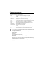
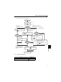

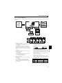


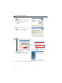


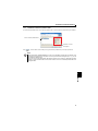
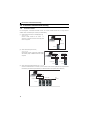
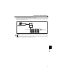
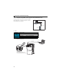
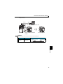


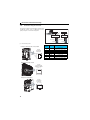
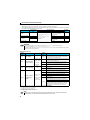
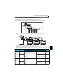

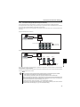
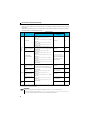
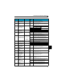
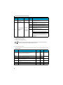
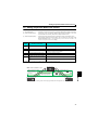

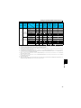
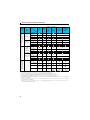
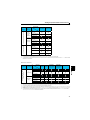
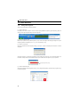

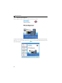
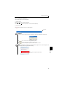
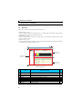
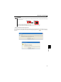
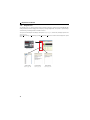
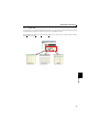
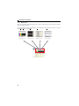
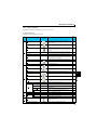

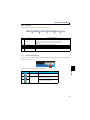

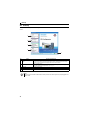
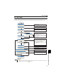

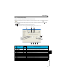
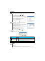
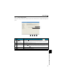
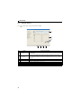
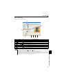


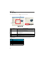
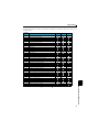
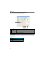
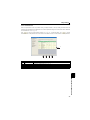

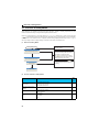
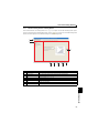
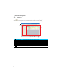


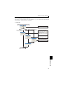

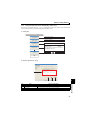
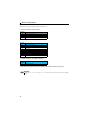

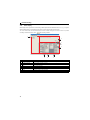
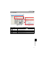
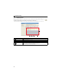
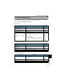
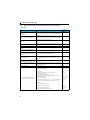
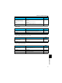

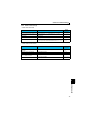
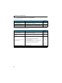
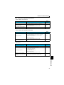
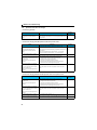
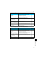
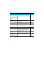

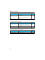
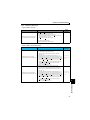
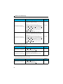
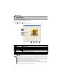

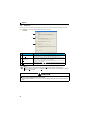
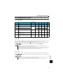
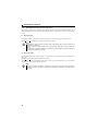
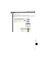

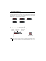
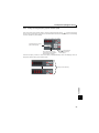
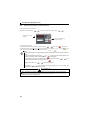

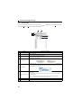

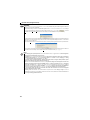

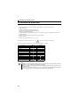
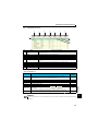

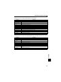
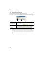

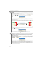
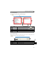

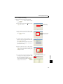
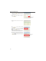

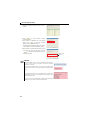

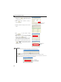
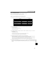

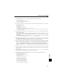
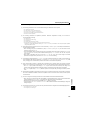
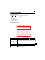

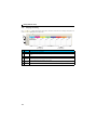
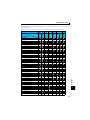

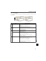
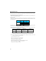
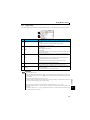
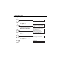
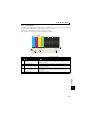

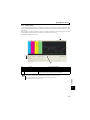
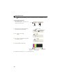
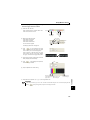
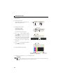
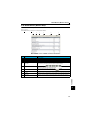
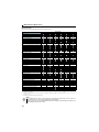
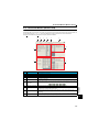
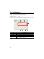
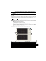
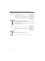

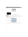
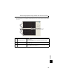
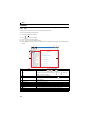


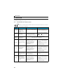
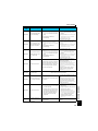
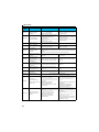


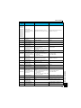

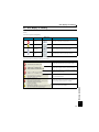


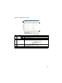
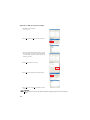

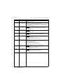


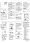


![福岡線 ほか [特急][急行]](http://vs1.manualzilla.com/store/data/006644047_2-4f69188fc040c5b73422fc9b702a6276-150x150.png)