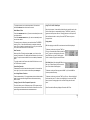
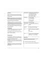
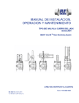
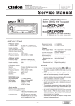
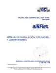
1
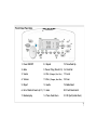
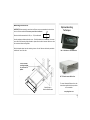
MRD-60 Marine AM / FM / CD / MP3 Receiver
Installation and Operation Manual
Poly Planar Group LLC 1352 Charwood Road, Hanover, MD 21076 PH: 410-761-4000
1
Contents
MRD-60 Audio System
Features:
Plays CD, CDR,CDR-W, MP3, WMA discs
Features
2
Waterproof Front Panel
Schematic
5
Stainless Steel Chassis
Connections
4
Conformal coated circuitry
Operation
7-9
Audio Expansion Port™ for easy system expansion
General controls
7-9
Stereo Auxiliary inputs (for TV , MP3 etc.)
Radio
7-9
Highly visible back lighted display
Clock
7
Ergonomic controls
CD / MP3 Player
8-9
Auxiliary Inputs
4,10
Automatic distortion control
Equalized for Marine acoustics
Infrared Remote compatible
Accessories/ Expansion Port
4, 10
Specifications
11
10 - 40 Sec. Anti skip CD deck
18 Presets for FM, 12 Presets for AM
2
2
Front Panel Functions
20
3
16
Display
5
1
17
18
15
2
19
4
6
7
8
9
12
10
11
14
13
1. Power ON/OFF
8. Repeat
15. Tune/Seek Up
2. Mute
9. Pause / Play (Preset # 4) 16. Clock Set
3. Source
10. Disc- (Changer, Prev. Disc)
17. Local
4. Volume
11.Disc+ (Changer, Next Disc)
18. Scan
5. IR port
12. Audio
19. Radio Band
6. Intro /Station Presets (6-11) 13. Auto
20. Front Panel Latch
7. Random play
21. CD Eject (Inside Door)
14. Tune /Seek Down
3
3
MRD-60, Rear Chassis Connections
See page 10 for connection details
DIN Port for CD Changer
or IP100 MP3 dock
Aux In 1
Aux In 2
Auxiliary Input connections (2)
for MP3 Players , TV audio, Satellite radio or other Audio device
with Audio output
Variable level output
for additional zone
amps or other audio
devices.
Main Connector for Radio.
Use supplied ‗Pigtail‖ or
OEM harness for connections.
IMR-2, IMR-4 or other
control module connection
4
4
Power & Speaker Harness Connections
Important! Disconnect power before installation.
12v out (low current)
Relay trigger
If you are not familiar with this type of installation
seek professional assistance
To Radio
Use the wired plug end
(Pig tail) provided to
make power and speaker
connections according to
the diagram on the right.
Using this connector will make it easy
to disconnect the radio for adding additional features or service. Removing
the factory plug end will void warranty
The 12v Positive and Negative connection should be min. 16 or 14 AWG
depending on length to the battery.
Be sure to observe the correct polarity
on the speaker connections
Receiver Side
5
5
Mounting Instructions:
IMPORTANT! Before mounting be sure there is sufficient room to accommodate the unit and that
there is sufficient ventilation. Disconnect power before installation.
Optional Mounting
Techniques
Receiver should be mounted within 30º (+ or— 15º)from Horizontal
Use the template provided to make the cutout. For blind installations (no rear access) the center
screw will hold the mounting blocks/brackets in place while the radio is mounted. Be sure to make
all connections before inserting Radio.
With the faceplate down insert the remaining 4 screws. Use the 5mm nut and bracket provided to
stabilize the rear of the radio.
RM –10 Underdash or Overhead Mount
WC-70 Bracket mount Radio Cover
Plastic Blocks or
Stainless Steel Brackets
For more information Please refer to the
instructions supplied with these products
or on our website:
www.polyplanar.com
6
6
Getting Started….
Power On / Off
Push (1)to power on unit , Push again to turn unit off.
Adjusting the Volume
Rotate Volume knob (4) to increase or decrease volume level. Current
setting is displayed for a few seconds.
Mute
Push (2) to mute sound, push again to resume
Program Selection
Press the Source button (3) to cycle through the available program
sources: Tuner>CD>CD Changer> AU-1> AU-2> Tuner
If a source is not active or disconnected that source will not appear.
If the CD Changer is attached but has no magazine inserted it will display
“EJECT”
Adjusting the Audio levels
Pressing AUDIO button (12) will indicate BAS (Bass Level) TRE (Treble)
BAL (Balance) or Fade. When the desired function is on the screen use the
volume knob to adjust values. Display will return to Volume mode after 3
seconds.
Bass and Treble: “C - 0”indicates center, -2 to –12 is Bass cut +2 to +12 is
increased level.
Balance: “C 0” indicates center, L1 to L15 indicates left bias. R1 to R15
Setting The Clock:
Hold the SET button (16) for 2 seconds until the first digit of the time
flashes. Use the TUNE/SEEK-UP button (15) or TUNE/SEEK Down (14) to set
the Hour.
Press the SET button to toggle the display between Clock and Radio
Modes.
Opening and Closing the front panel:
Place thumb on the front panel latch button (20 ) Firmly depress the button
while pulling the front panel open. Keep door firmly closed except when
changing discs.
Radio Operation:
Press the SOURCE button (3)to select the Radio Mode. Pressing the Band
Button (19) will toggle through the available radio modes: FM1, FM2, FM3,
AM1, AM2. Each band stores up to 6 independent presets, for a total of
18 FM and 12 AM presets.
Automatically setting the presets:
To automatically set the presets to the next higher stations, press the
preset button (6-11) from which to start programming. Hold the AUTO
button (13) for at least 2 seconds. The current preset and additional preset memories up to P6 will be programmed with the next tunable stations.
To select only the strongest stations, be sure the unit is set to LOCAL
mode (17).
All 18 FM and 12 AM presets can be set sequentially by selecting the next
band and continuing the operation during auto programming.
indicates right bias.
Fade: “C 0” indicates center, F1 to F15 indicates front bias. R1 to R15 indi-
cates rear bias.
7
7
To program a preset, tune in the desired station. Push and hold
the desired PRESET button for at least 2 seconds.
Using The CD / MP3 / WMA Player
Seek & Manual Tune:
Open the front panel. Insert the disc (label side up!) partially into the slot
and it will be drawn in automatically and play. The DISC IN symbol will
appear and the Play timer will start. Changing the source will stop the CD
deck and leave the disc in the bay. Press the EJECT button to eject or
change the disc.
Press the TUNE/SEEK-UP button (15) once to auto-matically tune to the
next higher station.
Press the TUNE/SEEK-DOWN button (14) once to automatically tune to
the next lower station
To manually tune to a frequency, press and hold either TUNE/SEEK
button for 2 Sec. . When the desired station is reached, release the
button. The unit remains in manual tune for 3 sec. So you can still fine
tune. After 3 seconds unit returns to Seek mode.
Scan Function:
Select any AM or FM station and press SCAN (18) to listen to a few
seconds of each station. The display will flash and scan up for the next
station. To stop the scan and listen to the current station press SCAN
again.
The radio remains in the Scan mode until the SCAN button or one of
the TUNE buttons is pressed.
Preset Scan Function:
Press AUTO The radio will scan the station presets for 3 seconds from
low to high. If you wish to remain on the station press SCAN again .
Local /Long Distance Function:
Press the LOCAL button (17) to toggle between local and distant station
mode. In Local mode the strongest stations will be selected during
SEEK or Scan.
Changing Tuner for US or European Frequencies:
The radio is factory set to US frequency steps. For European use disconnect power and reset switch on the bottom of the radio to the European setting. Power must be off or the reset must be used.
Display Modes:
CD: When playing an audio CD the runtime track and will be displayed.
To advance to the next track press TUNE up
(15) once. Press and hold will fast forward the
track To return to the beginning of the track
press TUNE down (14) once. Pressing again
within 1 second will play the next track down.
MP3 / WMA Discs: When playing MP3 Discs the
disc type, Folder/Directory and the track of
the current folder will be displayed
To advance to the next Directory press the DISC + (11) Use the DISC– to
choose a previous Directory.
To advance to the next track press TUNE up (15) once. Press and hold will
fast forward the track To return to the beginning of the track press TUNE
down (14) once. Pressing again within 1 second will play the next track
down.
After 5 seconds the Directory display will revert to Run Time.
8
8
INTRO, SCAN
Unit will not turn on
- Check Power Connections and voltage to unit
- Check Fuses (Red 10A, Yellow 1A)
- Check front panel for stuck buttons.
- Press reset button (see page 9)
CD will not play
- Check disk for Damage
- Try another CD/MP3 disc
- Check for stuck buttons
- Press reset button
Volume up stops but
indication continues
to ―31‖
- Check available voltage
- This indicates insufficient wire size on power
connection
Error Codes
Error Codes are indicated on the Display
E-03
- Read Error, Possible bad Disc , Retry with new
disc
-Try reset button
E– 07
- General Error code. This normally indicates a
CD Deck failure . Contact Service Center
CD: Press the INTRO button (6) to enter into Scan Mode, SCN will
appear in the left side of the display. In this mode the first 10 seconds
of each track will play.
MP3 Disc: If the disc is an MP3 the first 10 seconds of each track will
play and then advance to the next directory. Press the INTRO button
for 3 seconds and DCN will appear in the display. In this mode the first
10 seconds of the first track in each Directory will play.
CD Changer: If an MCD6 changer is installed pressing the INTRO
button will show SCN in the left side of the display. The main display
will show which CD is playing. In this mode the first 10 seconds of each
track of each CD in the magazine will play. Pressing INTRO for 3 seconds will change the display to CDC and play the first ten seconds of
the first track on each disc.
RANDOM, REPEAT
Press RANDOM button to play the tracks of the current CD or MP3 disc
in random order. RDM will appear on the left side of the display.
Press the REPEAT button and the current song will replay. RPT will
appear on the left side of the display.
TROUBLESHOOTING
Front Panel buttons: It is possible to press the elastomeric buttons in
a way that will allow them to stick under the panel face. This will stop
further function. Simply push again to re-center.
Reset Button: A system reset button is located inside the front panel.
Use a paperclip or thin rod to press the rest button if required. This will
restore factory defaults.
Fogged CD or lens: This may occur in certain conditions. Wipe CD
with soft dry cloth. The optical components will return to normal when
the radio warms up.
Repair / Returns
If your Poly Planar radio is not functioning correctly contact our Service
Department: Ph. 410-761-4000 or Fax: 410-761-6274
All returns must have a Return Authorization number
No returns will be accepted without a Return Authorization Number
9
9
Accessories
Auxiliary Inputs 1 & 2
Remote Control of the radio is possible with a Poly Planar MRR2 Wireless infrared remote control. The IR port is located next to the volume
knob and must be in line of site for the remote to operate.
The 2 RCA Type connections labeled AUX-IN-1 and AUX-IN-2 can be
used to input audio signals from other devices such as MP3 Players
and TV, DVD players.
The Audio Expansion Port (Page 4) is designed to accommodate various modules to enhance the capabilities of the system.
Use the SOURCE button (3) to toggle to this input. The display will
show AU-1 or AU-2
Audio Output
IMR-4: Input Output Module has 2 input ports and 3 Output ports
If an IMR-4 is installed the Audio ports on the back of the radio will be
disabled and the ports on the IMR-4 must be used for AU-1 and AU-2
functions.
The AUDIO OUT connection is used to output variable level audio from
the receiver to other devices such as zone amps or other systems.
The Output volume is determined by Volume setting on the receiver.
The fixed level output port is used to feed a separate zone amp that has
it’s own volume control like the ME-50.
The Variable level outputs (Front & Rear , Right &Left) mimic the output
of the tuner. These outputs are generally used to feed a 2 or 4 channel
Amplifier where the volume is controlled by the MRD-60 Receiver.
For more information see the instructional material included with the IMR
-4.
Control Modules for Spa Applications: The MRD60 expansion port can
support control modules for full spa control applications. These are
OEM applications.
Module Connection Priority: Multiple modules can be attached to the
Expansion Port. Each Module has a Priority designation on the label.
Modules should be “Daisy Chained” in the Alfa Numeric order listed in the
labels. (B1-B3 –C2 etc.)
IIMPORTANT! Disconnect power before installing Modules.
10
10
Specifications
8.125” (206mm)
Tuner
FM usable sensitivity
10dBf
FM 50 dB quieting sensitivity
15dBf
FM alternate channel selectivity
90dB
FM stereo separation @1kHz, 60dBf
30dB
AM usable sensitivity
30uV
2.750‖
(70mm)
Depth = 7 5/8 (194mm)
CD/MP3/MWA Deck
WA RRA NTY
Sampling Frequency (8x oversampling)
44.1kHz
Channel separation @ 1 kHz
80dB
manship for a period of two years. N o finished goods or parts may be returned
SNR
90dBA
for repair or replacement without a Poly-Planar RMA (Return Merchandise A u-
Freq. To noise response @ +/- 1dB
20-20kHz
thorization) number.
Audio
Max Power (45x4)
180W
Continuous Power, 4 Ohms, 1% THD
18Wx4
General
Poly-Planar products are warranted to be free of defects in materials and work-
Warranty is subject to proper installation and operation within published specifications. Poly-Planar will repair or replace, at its discretion, any returned unit determined to be defective. This warranty does not extend to the costs incurred in the
removal or reinstallation of the unit.
Nominal power supply
14.4 VDC
Allowable power supply
10.8 -15.6 VDC
Current consumption
< 10 amp
Poly-Planar Group LLC be liable for special, incidental, or consequential cost or
Speaker impedance
4 - 8 ohms
damages.
Poly-Planar warranty does not cover damage occurred in transit, accident, abuse,
misuse, negligence, fire flood, lightning or unauthorized service. In no event shall
Poly-Planar Group LLC 1352 Charwood Road, Hanover, MD 21076
410-761-4000 E-Mail: [email protected] Website: www.polyplanar.com
11
11