1
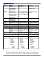
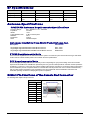
MultiModem® iCell
Intelligent Wireless Modem
User Guide
Copyright and Technical Support
MultiModem® iCell User Guide
Intelligent Wireless Modem
MTCMR-H, MTCMR-E, MTCMR-G-F4
S000455B, Revision B
Copyright
This publication may not be reproduced, in whole or in part, without prior expressed written permission from Multi-Tech
Systems, Inc. All rights reserved.
Copyright © 2009 - 10 by Multi-Tech Systems, Inc.
Multi-Tech Systems, Inc. makes no representation or warranties with respect to the contents hereof and specifically disclaims
any implied warranties of merchantability or fitness for any particular purpose.
Furthermore, Multi-Tech Systems, Inc. reserves the right to revise this publication and to make changes from time to time in the
content hereof without obligation of Multi-Tech Systems, Inc., to notify any person or organization of such revisions or changes.
Check Multi-Tech’s Web site for current versions of our product documentation.
Revision History
Revision
A
B
Date
Description
05/27/09
04/09/10
Initial release.
Add Universal IP, USB support, Windows Installer, and a Rev C back panel.
Trademarks and Logos
The Multi-Tech logo and MultiModem are registered trademarks of Multi-Tech Systems, Inc. Windows is a registered trademark
of Microsoft in the U.S. and other countries. Other trademarks and trade names mentioned in this publication belong to their
respective owners.
Contacting Multi-Tech Support
In order to better serve our customers, manage support requests and shorten resolution times, we have created the online web
portal allowing you to submit questions regarding Multi-Tech products directly to our technical support team. Get answers to
your most complex questions, ranging from implementation, troubleshooting, product configuration, firmware upgrades and
much more.
To create an account and submit a Support Case on the Portal, visit https://support.multitech.com
Online Web Portal
https://support.multitech.com
The Knowledge Base provides immediate answers to your questions and gives you access to support resolutions for all MultiTech products. Visit our support area on the website for other support services.
Knowledge Base and Support Services
www.multitech.com/support.go
World Headquarters
Multi-Tech Systems, Inc.
2205 Woodale Drive
Mounds View, Minnesota 55112
Phone: 763-785-3500 or 800-328-9717
Fax: 763-785-9874
Technical Support
Business Hours: M-F, 9am to 5pm CST
Country
By Email
By Phone
Europe, Middle East, Africa:
U.S., Canada, all others:
[email protected]
[email protected]
+(44) 118 959 7774
(800) 972-2439 or (763) 717-5863
Warranty
To read the warranty statement for your product, please visit:
2
http://www.multitech.com/warranty.go
Multi-Tech Systems, Inc MultiModem iCell Intelligent Modem User Guide
Table of Contents
Contents
Chapter 1 – Product Description and Specifications ............................................................... 4
Product Description ................................................................................................................................................................... 4
Universal IP ........................................................................................................................................................................ 4
MultiModem MTCMR-H (HSDPA) ...................................................................................................................................... 5
MultiModem MTCMR-E (EDGE) ........................................................................................................................................ 5
MultiModem MTCMR-G-F4 (GPRS) ................................................................................................................................... 5
Safety ........................................................................................................................................................................................ 6
General Safety ................................................................................................................................................................... 6
RF Interference Issues ....................................................................................................................................................... 6
Vehicle Safety .................................................................................................................................................................... 6
Maintenance of the Wireless MultiModem .......................................................................................................................... 6
Handling Precautions ......................................................................................................................................................... 6
Front Panel ................................................................................................................................................................................ 7
LEDs .................................................................................................................................................................................. 7
Signal LEDs........................................................................................................................................................................ 7
Back Panels............................................................................................................................................................................... 8
Package Contents ..................................................................................................................................................................... 8
Interfaces ................................................................................................................................................................................... 8
Specifications ............................................................................................................................................................................ 9
RF Specifications..................................................................................................................................................................... 10
Antenna Specifications ............................................................................................................................................................ 10
GSM/EGSM Antenna Requirements/Specifications ......................................................................................................... 10
Antennas Available from Multi-Tech Systems, Inc. .......................................................................................................... 10
PTCRB Requirements Note ............................................................................................................................................. 10
FCC Requirements Note .................................................................................................................................................. 10
RS232 9-Pin Functions of the Female End Connector ............................................................................................................................... 10
GPIO (General Purpose Input/Output) 6-Pin Connector .......................................................................................................... 11
GPIO DC Characteristics.................................................................................................................................................. 11
Chapter 2 – Activation and Installation.................................................................................... 12
Activate Your Wireless Account............................................................................................................................................... 12
Insert the SIM Card into Holder, If required ............................................................................................................................. 12
Connect the Antenna, Serial Cable, GPIO Cable, and Power ................................................................................................. 13
Optional – Attach the Modem to a Flat Surface ....................................................................................................................... 14
UIP USB CDC-ACM Virtual COM Port Installation .................................................................................................................. 15
Install the Modem Driver................................................................................................................................................... 16
Chapter 3 – Using Your Wireless Modem ................................................................................ 20
Phone Numbers for the Wireless Modem ................................................................................................................................ 20
Examples of Useful AT Commands ......................................................................................................................................... 20
Verifying Signal Strength .................................................................................................................................................. 20
Checking Network Registration and Roaming Status ....................................................................................................... 20
Checking the Modem’s Identity ........................................................................................................................................ 20
Connecting to the Internet ....................................................................................................................................................... 21
Connecting to a GPRS/EDGE/HSDPA Network for Internet Access ................................................................................ 21
Create Your Dial-Up Connection in Windows Vista and XP ............................................................................................. 22
Generic Dial-Up Method - Non-Windows.......................................................................................................................... 23
Appendix A – Regulatory Compliance ..................................................................................... 24
EMC, Safety, and R&TTE Directive Compliance .............................................................................................................. 24
International Modem Restrictions ..................................................................................................................................... 24
FCC Part 15 Class B Statement ....................................................................................................................................... 24
Industry Canada ............................................................................................................................................................... 24
Appendix B – DC Power Cable ................................................................................................. 25
DC Power Cable Dimensions ........................................................................................................................................... 25
Appendix C - Waste Electrical and Electronic Equipment (WEEE) Statement ..................... 26
Appendix D – ROHS HT/TS Substance Concentration ........................................................... 27
Restriction of the Use of Hazardous Substances (RoHS) ................................................................................................ 27
Multi-Tech Systems, Inc. MultiModem iCell Intelligent Wireless Modem User Guide
3
Chapter 1 – Product Description and
Specifications
Product Description
The Multi-Tech MultiModem® iCell is a mid-range wireless modem. It is available in three models that require a SIM. All models
contain an embedded TCP/IP protocol stack for Internet connectivity, serial and USB connectors for modem configuration, and a
General Purpose Input/Output (GPIO) connector for customer interface connection. All MultiModem iCells can be desktop or
panel mounted.
The MultiModem iCell modems are available in four models:
Model
Description
MTCMR-H (HSDPA)
Standards based tri-band UMTS/HSDPA performance
MTCMR-E (EDGE)
Quad-band E-GPRS Class 10 performance
MTCMR-G-F4 (GPRS)
Quad-band GSM/GPRS Class 10 performance
All models contain an embedded TCP/IP protocol stack to bring Internet connectivity to any device without making changes to
its hardware design. Using the Internet protocols and the wireless connection to an IP network, the modems send and receive
data over the Internet. The modems offer short message service (SMS) features such as text and PDU, Point-to-point (MT/MO)
and cell broadcast.
The MultiModem iCell modems deliver some of the fastest cellular wireless data speeds using the various Internet protocols.
This is ideal for highly data-intensive applications such as remote video surveillance and other multimedia applications where
you are sending digital images, web pages and photographs.
The MultiModem iCell modems are designed around a wide variety of interface options including serial RS-232, USB, and
General Purpose Input/Output (GPIO). The serial RS-232 and USB connections provide seamless connectivity for configuration
of your application. The GPIO interface provides five user configurable GPIO’s as CMOS input or output ports to be connected
to a customer’s peripheral device. A customer application in which the GPIO interface could be used is one with a monitoring
device connected to the GPIO interface in which the monitoring device triggers an event in the IP stack to establish a TCP or
UPD socket connection or send an email stating that the monitoring device was triggered by high water.
Universal IP
All MultiModem iCell modems are equipped with an embedded TCP/IP protocol stack to automate the connection process
and open a socket for bidirectional data transmission. Multi-Tech’s Universal IP supports Telnet, SMTP/POP, FTP, TCP,
UDP, PPP as well as other automatic call management options.
AT Commands: The embedded TCP/IP stack on the MultiModem iCell modems is configured using the
Universal IP (UIP) AT Commands. These commands are documented in the Reference Guide document
number S000457x.
4
Multi-Tech Systems, Inc. MultiModem iCell Intelligent Wireless Modem User Guide
Chapter 1 – Product Description and Specifications
MultiModem MTCMR-H (HSDPA)
The MultiModem MTCMR-H wireless modem delivers some of the fastest cellular data speeds by utilizing HSDPA
technology. It allows users to connect to the Internet and send and receive data faster than possible with an ordinary
GSM/GPRS network making it ideal for highly data-intensive applications. Based on industry-standard open interfaces, the
MultiModem MTCMR-H wireless modem is equipped with quad-band, high-speed RS232 technology, which means it can
be used worldwide on all existing GSM networks.
AT Commands: The MultiModem MTCMR-H wireless modem is configured using the HSDPA AT
Commands. These commands are documented in the Reference Guide for the MultiModem Wireless
HSDPA Modems, document number S000453x.
MultiModem MTCMR-E (EDGE)
The MultiModem EDGE wireless modem delivers some of the fastest cellular wireless data speeds utilizing EDGE
technology. It allows users to connect to the Internet, send and receive data up to three times faster than possible with an
ordinary GSM/GPRS network making it ideal for highly data-intensive multimedia applications.
AT Commands: The MultiModem MTCMR-E wireless modem is configured using the EDGE AT
Commands. These commands are documented in the Reference Guide for the MultiModem Wireless EDGE
Modems, document number S000371x.
MultiModem MTCMR-G-F4 (GPRS)
The MultiModem GPRS wireless modem offers standards-based quad-band GSM/GPRS Class 10 performance. Ready to
deploy, standalone data modem allows developers to add wireless communication to products with a minimum of
deployment time and expense.
AT Commands: The MultiModem MTCMR-G wireless modem is configured using the GPRS AT
Commands. These commands are documented in the Reference Guide for the MultiModem Wireless GPRS
Modems, document number S000293x and also the Reference Guide for the Universal IP Commands,
document number S000457x.
Multi-Tech Systems, Inc. MultiModem iCell Intelligent Wireless Modem User Guide
5
Chapter 1 – Product Description and Specifications
Safety
General Safety
The modem is designed for and intended to be used in fixed and mobile applications. “Fixed” means that the device is physically
secured at one location and is not able to be easily moved to another location. “Mobile” means that the device is designed to be
used in other than fixed locations.
Caution: Maintain a separation distance of at least 20 cm (8 inches) between the transmitter’s antenna
and the body of the user or nearby persons. The Modem is not designed for or intended to be used in
portable applications within 20 cm. (8 inches) of the body of the user.
RF Interference Issues
It is important to follow any special regulations regarding the use of radio equipment due in particular to the possibility of radio
frequency, RF, interference. Please follow the safety advice given below carefully.
●
●
●
●
●
●
Switch OFF your MultiModem when in an aircraft. The use of cellular telephones in an aircraft may endanger the
operation of the aircraft, disrupt the cellular network and is illegal. Failure to observe this instruction may lead to
suspension or denial of cellular telephone services to the offender, or legal action or both.
Switch OFF your MultiModem when around gasoline or diesel-fuel pumps and before filling your vehicle with fuel.
Switch OFF your MultiModem in hospitals and any other place where medical equipment may be in use.
Respect restrictions on the use of radio equipment in fuel depots, chemical plants or where blasting operations are in
progress.
There may be a hazard associated with the operation of your MultiModem close to inadequately protected personal
medical devices such as hearing aids and pacemakers. Consult the manufacturers of the medical device to determine
if it is adequately protected.
Operation of your MultiModem close to other electronic equipment may also cause interference if the equipment is
inadequately protected. Observe any warning signs and manufacturers’ recommendations.
Vehicle Safety
●
●
●
●
Do not use your MultiModem while driving.
Respect national regulations on the use of cellular telephones in vehicles. Road safety always comes first.
If incorrectly installed in a vehicle, the operation of MultiModem telephone could interfere with the correct functioning of
vehicle electronics. To avoid such problems, be sure that qualified personnel have performed the installation.
Verification of the protection of vehicle electronics should be part of the installation.
The use of an alert device to operate a vehicle’s lights or horn on public roads is not permitted.
Maintenance of the Wireless MultiModem
Your wireless MultiModem is the product of advanced engineering, design, and craftsmanship and should be treated with care.
The suggestions below will help you to enjoy this product for many years.
●
●
●
●
●
●
●
Do not expose the MultiModem to any extreme environment where the temperature or humidity is high.
Do not attempt to disassemble the MultiModem. There are no user serviceable parts inside.
Do not expose the MultiModem to water, rain, or spilled beverages. It is not waterproof.
Do not abuse your MultiModem by dropping, knocking, or violently shaking it. Rough handling can damage it.
Do not place the MultiModem alongside computer discs, credit or travel cards, or other magnetic media. The
information contained on discs or cards may be affected by the phone.
The use of accessories not authorized by Multi-Tech or not compliant with Multi-Tech’s accessory specifications may
invalidate the warranty of the MultiModem.
In the unlikely event of a fault in the MultiModem, contact Multi-Tech Technical Support.
Handling Precautions
All devices must be handled with certain precautions to avoid damage due to the accumulation of static charge. Although input
protection circuitry has been incorporated into the devices to minimize the effect of this static build up, proper precautions should
be taken to avoid exposure to electrostatic discharge during handling and mounting.
6
Multi-Tech Systems, Inc MultiModem iCell Intelligent Modem User Guide
Chapter 1 – Product Description and Specifications
Front Panel
The front panel is designed with two groups of LEDs that display modem activity and signal strength. The first group of LEDs
display modem activity, such as transmit and receive data, carrier detection, link status, terminal ready indicating connection to
the pc, and the power indicator. The three Signal LEDs display the signal strength level of the wireless connection. The SIM
door on the right side of the modem provides access to the SIM card holder for those configurations.
LEDs
LED Indicators
TD
Transmit Data. Lit when modem is transmitting data. Not valid while in USB mode.
RD
Receive Data. Lit when modem is receiving data. Not valid while in USB mode.
CD
Carrier Detect. Lit when data connection has been established. Not valid while in USB mode.
LS
Link Status Dependent on Model
MTCMR-G
Continuous “on”
state indicates that the
wireless modem is not
registered on the
network.
Flashing state
indicates registration
on network.
Off state. Modem is
off (not ready) or in
download mode.
TR
PWR
Signal
MTCMR-H
Continuous “on” state
indicates that the wireless
modem is registered on the
network.
Flashing state Indicates
attempted registration on
network.
Off state. Modem could
not register
MTCMR-E
Permanently off. ME is in one of the following
modes: Power Down mode, Airplane mode NonCyclic Sleep mode with no temporary wake-up
event in progress.
600 ms on/600 ms off
Limited Network Service: No SIM card inserted
or no PIN entered, or network search in progress
or ongoing user authentication, or network login
in progress.
75 ms on/3 sec off
Idle mode: The mobile is registered to the GSM
network (monitoring control channels and user
interactions). No call is in progress.
75 ms on/ 75 ms off/75 ms on/3 sec off
One or more GPRS contexts activated.
500 ms on/ 25 ms off
Packet switched data transfer in progress.
Permanently on
Depending on type of call:
Voice call – Connected to remote party
Data call – Connected to remote party or
exchange of parameters while setting up or
disconnecting a call.
Terminal Ready. Lit when modem is transmitting data. Not valid while in USB mode.
Power. Indicates presence of DC power when lit.
Indicates the wireless signal strength. Refer to Signal Strength LEDs below.
Signal LEDs
In order to verify signal strength, you must use a terminal application such as HyperTerminal. Refer to Examples of Useful AT
Commands in Chapter 3 of this guide.
Multi-Tech Systems, Inc. MultiModem iCell Intelligent Wireless Modem User Guide
7
Chapter 1 – Product Description and Specifications
Back Panels
The reason for two different back panels is that the Rev B back panel could only support a 5Volt input on pins 1 and 2. The Rev
C and later back panel can support a 24Volt input on pins 1 and 2. The way to distinguish between Rev B and Rev C back
panels is that the RS-232 connector for the Rev B back panel is more to the left side of the back panel. The Rev C and later
back panel is 1.73 inches from the left side of the unit to the center point of the RS-232 connector.
Rev B
Rev C and later
Package Contents
Unbundled Package
with No Accessories
1 modem
1 Quick Start Guide
1 MultiModem CD
Note: You must supply mounting
screws, AC or DC power
supply, and an antenna.
Bundled Package
With Accessories
1 modem
1 antenna
1 RS232 cable
1 USB cable
1 GPIO cable
1 power supply
1 Quick Start Guide
1 MultiModem CD
Note: You must supply mounting screws.
Note: Your wireless provider will supply the SIM card.
Interfaces
The MultiModem has several interfaces:
●
●
●
●
●
●
●
8
LED function indicating operating status
External antenna (via SMA connector)
Serial and control link (via 9-pin DB9 female)
USB 2.0 full speed, CDC-ACM Compliant
General purpose input/output (via 6 pin 2x3 style connector)
Power supply (via 2.5mm miniature power jack)
SIM card holder
Multi-Tech Systems, Inc MultiModem iCell Intelligent Modem User Guide
Chapter 1 – Product Description and Specifications
Specifications
Features
MTCMR-H
Performance
MTCMR-E
Up to 14.4K bps, non-transparent
Up to 14.4K bps transparent and nontransparent
Text & PDU, Point-to-Point (MO/MT),
cell broadcast
RF Antenna: 50 ohm SMA (female
connector)
Standard 1.8 and 3V SIM receptacle
DE9
6 pin 2x3 style
2.5mm miniature(screw-on)
Text & PDU, Point-to-Point, cell
broadcast
RF Antenna: 50 ohm SMA (female
connector)
Standard 1.8 and 3V SIM receptacle
DE9
6 pin 2x3 style
2.5mm miniature(screw-on)
Voltage
Power*
9V to 32 VDC
9V to 32 VDC
9V to 32 VDC
Physical
Description
Operating
Temperature **
Storage Temp
Humidity
4.2” Wx1.1”Hx3.4”D 2lbs
12.5 cmW x2.7cmHx 8.6cmD 0.23Kg
-30° to +60° C
UL listed @ 40°
-40° to +85° C
Relative humidity 20% to 90%
noncondensing
EMC Compliance
FCC Part 15
EN55022
EN55024
Radio Compliance
FCC Part 22, 24
RSS132,133
EN301 489-1
EN301 489-7
EN301 511
AS/ACIF S042.1, S042.3
Safety: UL60950-1
cUL60950-1
IEC60950-1
Network: PTCRB
Band, Frequency
Packet Data
Circuit-Switched
Data
Short Message
Services-SMS
Antenna
Connector
SIM Connector
RS232 Connector
GPIO Connector
Power Connector
Sleep .046A, .43W @ 9V, .021A,.42W @ 20V,
.014A, .45W @ 32V
Typical .325A,.2.99W @ 9V, .152A,3.04W @ 20V;
0.1A, 3.20W @ 32V
Max .532A,4.89W @ 9V, .225A,4.50W @ 20V,
.146A, 4.67W @ 32V
Peak. N/A
Certifications
EDGE: E-GPRS Class 10,
GPRS: Class 12
MTCMR-G-F4
HSDPA/UMTS
EDGE: Class 10
GPRS: Class 10
Quad-band
GSM/GPRS/EDGE/HSDPA
850/900/1800/1900 MHz
UMTS FDD: Band I/
Band II/Band V
HSDPA: UE CAT [1-6], 11, 12
supported,compressed mode
according to 3GPP TS5.212
EDGE: Class 10, full
PBCCH support, coding schemes
CS-9, Mobile station Class B
GPRS: Class 10, full PBCCH
support, coding schemes CS1-4,
Mobile station Class B
GSM: Asynchronous, nontransparent up to 9600bps
UMTS: Asynchronous,nontransparent up to 64K bps
Text & PDU,Point-to-Point
(MO/MT), cell broadcast
RF Antenna: 50 ohm SMA (female
connector)
Standard 1.8 and 3V SIM receptacle
DE9
6 pin 2x3 style
2.5mm miniature(screw-on)
GPRS: Class 10
Quad-band GSM 850/900/1800/1900 Quad-band GSM
MHz
850/900/1800/1900 MHz
EDGE: E-GPRS Up to 240K bps,
Up to 85.6K bps, coding schemes
coding scheme MCS-9, mobile station CS1 to CS4
Class B, LLC layer, 4 time slots
GPRS: Full PBCCH support, coding
scheme 1-4, mobile station Class B
Sleep .036A, .33W @ 9V, .023A,.46W @ 20V,
.014A, .45W @ 32V
Typical .120A,.1.11W @ 9V, .060A, 1.20W @ 20V;
.040A, 1.28W @ 32V
Max .345A,3.15W @ 9V, .158A, 3.16W @ 20V,
.102A, 3.26W @ 32V
Peak. 1.90A @9 V, 0.703A @ 20V, 0.468A @32V
4.2” W x1.1”Hx3.4”D 2 lbs
12.5cmW x2.7cmH x 8.6cmD 0.2Kg
-30° to +50° C
UL listed @ 40°
-40° to +85° C
Relative humidity 20% to 90%
noncondensing
EMC Compliance
FCC Part 15
EN55022
EN55024
Radio Compliance
FCC Part 22, 24
RSS132,133
EN301 489-1
EN301 489-7
EN301 511
AS/ACIF S042.1, S042.3
Safety: UL60950-1
cUL60950-1
IEC60950-1
Network: PTCRB
Sleep .035A, .32W @ 9V, .017A,.34W @ 20V, .012A,
.38W @ 32V
Typical .103A,.95W @ 9V, .046A,.92W @ 20V; .032A,
1.02W @ 32V
Max .183A,1.69W @ 9V, .086A,1.72W @ 20V,
.056A, 1.79W @ 32V
Peak. 1.180A @9 V, .530A @ 20V, .375A @32V
4.2” Wx1.1”Hx3.4”D 2 lbs
12.5cmW x2.7cmH x 8.6cmD 0.205Kg
-30° to +70° C
UL listed @ 40°
-40° to +85° C
Relative humidity 20% to 90%
noncondensing
EMC Compliance
FCC Part 15
EN55022
EN55024
Radio Compliance
FCC Part 22, 24
RSS132,133
EN301 489-1
EN301 489-7
EN301 511
AS/ACIF S042.1, S042.3
Safety: UL60950-1
cUL60950-1
IEC60950-1
Network: PTCRB
*
Multi-Tech Systems, Inc recommends that the customer incorporate a 10% buffer into their power source when determining product
load.
**
UL Listed @ 40°C. Limited by power supply. UL Certification does not apply or extend to an ambient above 40°C and has not been
evaluated by UL for ambient greater than 40°C
“UL has evaluated this device for use in ordinary locations only. Installation in a vehicle or other outdoor locations has not been
evaluated by UL. UL Certification does not apply or extend to use in vehicles or outdoor applications or in ambient above 40° C.”
Multi-Tech Systems, Inc. MultiModem iCell Intelligent Wireless Modem User Guide
9
Chapter 1 – Product Description and Specifications
RF Specifications
GSM 850
EGSM 900
GSM 1800
GSM 1900
Frequency RX
869 to 894 MHz
925 to 960 MHz
1805 to 1800 MHz
1930 to 1990 MHz
Frequency TX
824 to 849 MHz
880 to 915 MHz
1710 to 1785 MHz
1850 to 1910 MHz
RF Power Stand
2W at 12.5% duty
cycle
2W at 12.5% duty
cycle
1W at 12.5% duty
cycle
1W at 12.5% duty
cycle
Antenna Specifications
GSM/EGSM Antenna Requirements/Specifications
Frequency Range:
Impedance:
VSWR:
Typical Radiated Gain:
Radiation:
Polarization:
Wave:
824 – 960 MHz / 1710 – 1990 MHz
50 Ohms
<2.0:1
3 dBi on azimuth plane
Omni
Vertical
Half Wave Dipole
Antennas Available from Multi-Tech Systems, Inc.
Description
Part Number
Hinged Right Angle 900/1800 MHz Cellular Modem Antenna
Hinged Right Angle 800/1900 MHz Cellular Modem Antenna
Hinged Right Angle 850/900/1800/1900 MHz Cellular Modem Antenna
ANF1-1HRA
ANF2-1HRA
ANQB-1HRA
PTCRB Requirements Note
There cannot be any alteration to the authorized antenna system. The antenna system must be the same type with similar
in-band and out-of-band radiation patterns and maintain the same specifications.
FCC Requirements Note
The antenna gain, including cable loss, for the radio you are incorporating into your product design must not exceed the
requirements at 850 MHz and 1900 MHz as specified by the FCC grant for mobile operations and fixed mounted operations
as defined in 2.1091 and 1.1307 of the FCC rules for satisfying RF exposure compliance. The antenna used for transmitting
must be installed to provide a separation distance of at least 20cm from all persons and must not transmit simultaneously
with any other antenna transmitters. User and installers must be provided with antenna installation instructions and
transmitter operating conditions to satisfying RF exposure compliance.
RS232 9-Pin Functions of the Female End Connector
The following table explains the pin functions.
External Power
Signal
Pin 1 CD
Pin 2 RX
Pin 3 TX
Pin 4 DTR
Pin 5 GND
Pin 6 DSR
Pin 7 RTS
Pin 8 CTS
Pin 9 RI
10
IN/OUT
O
O
I
I
-O
I
O
O
Serial Cable
Female Connector
Multi-Tech Systems, Inc MultiModem iCell Intelligent Modem User Guide
Chapter 1 – Product Description and Specifications
GPIO (General Purpose Input/Output) 6-Pin
Connector
The GPIO pins are configured using Universal IP (UIP) AT Commands. Refer to the Universal IP (UIP) AT Command Reference
Guide on your MultiModem CD. The following table explains the GPIO functions:
Pin
Number
Pin 1
Pin 2
Pin 3
Pin 4
Pin 5
Pin 6
Description
GPIO 6-Pin
Connector
DIO 0
DIO 1
DIO 2 / ADC 0
DIO 3 / ADC 1
ADC 2
Gnd
The GPIO pins can be configured independent of each other. An explanation of the difference between the Rev B and Rev C
boards is provided in the Back Panel description in Chapter 1.
● Pin 1 Digital Input (5V tolerant TTL/CMOS levels) for Rev B, 24 Volt tolerent for Rev C and later.
●
Pin 2 Digital Input (5V tolerant TTL/CMOS levels) for Rev B, 24 Volt tolerent for Rev C and later.
●
Pin 3 can be configured as either Digital Input (5V tolerant TTL/CMOS levels) or Digital Output (3.3V High) or as an
ADC input (0 to 3.3V rail)
●
Pin 4 can be configured as either Digital Input (5V tolerant TTL/CMOS levels) or Digital Output (3.3V High) or as an
ADC input (0 to 3.3V rail)
●
Pin 5 is configured as an ADC input (0 to 3.3V rail)
●
Pin 6 is GND and must be connected to the ground of the attached device
GPIO DC Characteristics
Pins 1,2 - Rev B Board
Input Voltage
Parameter
Input Low-level Voltage
Input High-level Voltage
Min
-0.3
2.0
Max
0.8
5.5
Pins 1,2 - Rev C and later Board
Input Voltage
Parameter
Input Low-level Voltage
Input High-level Voltage
Min
0.3
3.0
Max
1.0
24
Parameter
Input Low-level Voltage
Input High-level Voltage
Min
-0.3
2.0
Max
0.8
5.5
Units
V
V
Parameter
Output Low-level Voltage
Output High-level Voltage
Min
0.0
2.9
Max
0.4
3.3
Units
V
V
Parameter
Output Current
Min
Max
2
Units
mA
Units
V
V
Units
V
V
Pins 3,4
Input Voltage
Pins 3, 4
Output Voltage
Pins 3,4
Output Current
Pins 1,2 are digital input only
Pin 5 is an analog input only
Pins 1-5 contain ESD protection
Multi-Tech Systems, Inc. MultiModem iCell Intelligent Wireless Modem User Guide
11
Chapter 2 – Activation and Installation
Activate Your Wireless Account
Please refer to the wireless account Activation Notices included with your unit and located on the MultiModem CD. Choose the
one for your wireless network provider and follow the directions to activate your account.
Phone Numbers for the Wireless Modem
Every wireless modem will have its own unique phone number. The phone number may simply be given to you by your wireless
service provider or it may be on the SIM card or both. Wireless provider implementations may vary.
Insert the SIM Card into Holder, If required
The MultiModem requires the power supply connection to begin operation. It also requires a SIM card (Subscriber Identity
Module) to operate on a GSM network. To install the SIM, do the following:
1. Using a small Phillips screwdriver, remove the two SIM door screws and remove the SIM door.
Note: When changing a SIM, ensure that power is removed from the unit.
2. Insert the SIM card into the card holder. The above graphic illustrates the correct SIM card orientation.
3. Verify that the SIM card fits into the holder properly and then replace the cover.
12
Multi-Tech Systems, Inc. MultiModem iCell Intelligent Wireless Modem User Guide
Chapter 2 – Activation and Installation
Connect the Antenna, Serial Cable, GPIO Cable,
and Power
1.
Connect a suitable antenna to the SMA connector (see antenna specifications in Chapter 1).
2.
If you are connecting to a serial interface, connect the DE9 connector (9-pin) of the RS232 cable to the RS232
connector on the modem and connect the other end to serial port on your PC.
If you are connecting to an USB interface, connect an USB cable to the USB connector on the back of the unit and
the other end to the USB port on your PC.
3.
Connect the GPIO cable to the I/O connector on the modem and the other end to the external device that the modem
is monitoring.
4.
Depending on the power source, connect either the power supply module with the appropriate blade or the optional
DC power cable. If you are using the power supply module, remove the protective shipping cover. Attach the
appropriate interchangeable blade piece to the power supply module.
Screw-on the power lead from the power supply module to the power connection on the modem. Now, plug the
power supply into your power source.
For Optional Direct DC Power
• Screw-on the DC power cable to the power connector on the modem.
• Then attach the two wires at the other end of the DC power cable to a DC fuse/terminal block on a vehicle in
which you are mounting the MultiModem.
• Connect red wire to the "+" (positive) terminal and black wire to the "–" (negative) terminal. Be sure the GND
connection is correct.
Warning: Over-voltage protection is provided on the device. To ensure complete protection, you may want to add
additional filtering to the DC input.
Note: For automotive application: according to the type of application, you can use permanent “+” or key-switched
“+” source. Connect the power supply to its source (for example, in a mobile situation, to the vehicle’s DC
fuse/terminal block).
Multi-Tech Systems, Inc. MultiModem iCell Intelligent Wireless Modem User Guide
13
Chapter 2 – Activation and Installation
Optional – Attach the Modem to a Flat Surface
Before you mount your modem to a permanent surface, verify signal strength, refer to Using Your Wireless Modem, Verify
Signal Strength in Chapter 3.
The modem can be panel mounted with screws spaced according to the measurement shown.
Note: Use either #4 or #6 pan head screws for all four mount locations.
14
Multi-Tech Systems, Inc MultiModem iCell Intelligent Modem User Guide
Chapter 2 – Activation and Installation
UIP USB CDC-ACM Virtual COM Port Installation
Windows XP, VISTA, 2003 Server, 2008 Server, Windows 7 (32-bit or 64-bit), Linux (Kernel 2.6.xx using CDC-ACM module) are
supported.
For Linux, a 2.6 kernel is required. The standard CDC-ACM driver will work.
For Windows XP, VISTA, 2003 Server, 2008 Server, and Windows 7, run the automatic installer from your product CD or run
install.bat from the UIP_VCOM_autoinstall directory on your product CD and proceed with the procedure below.
Note: Certain levels of Windows has an issue with their CDC-ACM driver (Usbser.sys). If you are having connection problems
(file download, web pages not loading) your version of Usbser.sys must be updated. Microsoft article 925681 documents this
issue and provides a fix. http://suport.microsoft.com/kg/925681
After installing the virtual com port, the correct modem driver may be installed to the com port (make sure the USB port of the
MTCMR is connected with a SIM card before the modem driver installation.
1.
Power on the MTCMR ensuring that the SIM card is installed prior to powering up.
2.
Ensure that the USB cable is connected to your pc.
3.
If any Windows Install Wizard pops up, close or cancel the wizard.
4.
Insert the product CD into a compatible drive.
5.
Click on the Preinstall Windows Drivers button from the main splash screen of the CD.
6.
Windows may pop-up a User Account Control window. Select the Continue button to continue with the driver
installation.
7.
Click on the Next button to start the driver pre-installation.
Multi-Tech Systems, Inc. MultiModem iCell Intelligent Wireless Modem User Guide
15
Chapter 2 – Activation and Installation
8.
There will be a transitory screen, then the process will complete. Click on the Finish button.
9.
Next, continue with installing the modem driver.
Install the Modem Driver
1.
2.
16
Click on the Control Panel button from the main splash screen on the CD.
The Control Panel is displayed, double-click on Phone and Modem Options icon. Then click on the Modems tab.
Multi-Tech Systems, Inc MultiModem iCell Intelligent Modem User Guide
Chapter 2 – Activation and Installation
3.
When this Phone and Modem Options screen appears, click on the Add button.
4.
On the Install New Modem screen, click Don’t detect my modem, I will select it from a list. Then click Next >.
5.
On the Install New Modem screen, click the Have Disk button to browse for the driver file on the MultiModem CD.
Then click Next>.
Multi-Tech Systems, Inc. MultiModem iCell Intelligent Wireless Modem User Guide
17
Chapter 2 – Activation and Installation
6.
Make sure that the MultiModem CD is inserted into your CD-ROM, browse to your MultiModem CD.
7.
Select the MTSMCIP_MTCMRIP.INF file.
Then click OK.
8.
In the Models window, scroll down the list of Models and select the model that is applicable to your modem.
Once you have selected your model, click on Next>.
18
Multi-Tech Systems, Inc MultiModem iCell Intelligent Modem User Guide
Chapter 2 – Activation and Installation
9.
You will now have to choose which com port the MultiModem is connected to.
If you know exactly which port your modem is on, click on that port; other wise, choose COM2 (most common). Click
Next >.
10. To finish the install, click on Finish.
You have now successfully installed the MultiModem driver to your PC.
Verifying That Your Modem Has Been Installed Successfully
1.
After you have successfully installed the MultiModem driver as stated above, you should be brought back to the Phone
and Modems Options screen. Make sure that the modem is now listed under the columns Modem and Attached To
(the correct com port).
2.
Highlight the modem and then click on Properties.
3.
A Properties screen will open for the Multi-Tech modem. Click on the tab labeled Diagnostics.
4.
In the middle of the screen, click on the Query Modem button. Windows will now try to query the Multi-Tech modem. If
this process passes, the second box on this screen will show the columns Command and Response.
Note: To make sure that the modem is correctly being queried, look at the LED lights of the modem after you click on
Query Modem. The TR light should come on and the TD and RD lights should flicker.
4.
If this process passes, then the modem should be properly installed and ready for use. Click OK to close the modem
Properties window. Then click on OK to close the Phone and Modem Options window.
Multi-Tech Systems, Inc. MultiModem iCell Intelligent Wireless Modem User Guide
19
Chapter 3 – Using Your Wireless Modem
Phone Numbers for the Wireless Modem
● Every wireless modem will have its own unique phone number.
● The phone number may simply be given to you by your wireless service provider or it may be on the SIM card or both.
Wireless provider implementations may vary.
Examples of Useful AT Commands
A Note About HyperTerminal
In order to verify signal strength and roaming status, you must use a terminal application such as HyperTerminal. To open this
program in Windows Vista or XP, go to Start > All Programs > Accessories > Communications > HyperTerminal. Other
Windows operating systems have similar paths to HyperTerminal. See your system’s online Help if you cannot find it.
A Note About AT Commands
AT commands can be used to operate, configure, and query your modem. AT commands for the MultiModem iCells are
published in separate Reference Guides included on the MultiModem CD and posted on the Multi-Tech web site.
The following two commands let you query signal strength and roaming status.
Verifying Signal Strength
Using HyperTerminal, type AT+CSQ
The modem responds with the received signal strength (rssi).
The modem responds with the received signal strength (rssi) and the channel bit error rate (ber).
RSSI ranges from 0 to 31.
AT+CSQ xx Values
0 - 10
11 - 20
21 – 31
99
Signal Strength Verification – RSSI
Signal Strength
LED Bars
Weak or Insufficient
1 Bar LED is lit
Average
1 Bar and 2 Bar LEDs are lit
Exceptional
1 Bar, 2 Bar, 3 Bar LEDs are lit
No signal
No light
BER ranges from 0 to 7 (Seven is the highest error rate).
Checking Network Registration and Roaming Status
In this procedure, you will verify that the MultiModem has been registered on the wireless network. Using
HyperTerminal, type AT+CREG?
The modem will respond in one of the following ways:
Value
0,0
0,1
0,5
Network Registration Verification
Network Registration Status
The modem is not registered on any network
The modem is registered on the home network
The modem is registered on a network and it is roaming
Note: If the modem indicates that it is not registered, verify the signal strength to determine if the problem is the
strength of the received signal.
Checking the Modem’s Identity
Use the ATI command (Note: This command is illustrated using the capital letter I after AT)
● Type ATI0 (Note: The command ends in a zero)
The manufacturing data displays. For example: Wavecom Modem Multiband G850 1900
● Type ATI3
The software version displays. For example: 651_09gg...
● Type ATI6
Displays modem data features. For example: data rates, data modes, fax classes.
20
Multi-Tech Systems, Inc. MultiModem iCell Intelligent Wireless Modem User Guide
Chapter 3 – Using your Wireless Modem
Connecting to the Internet
The Multi-Tech MultiModem iCell is designed for a GPRS wireless network. Internet access can be setup in Windows Dial-Up
Networking (DUN) of the computer that the MultiModem icell is serving. For a GPRS network, you have to create an Access
Point Name in the Phone and Modem Options dialog in Windows Control Panel and then create your Windows Dial-Up
Connection (DUN).
Connecting to a GPRS/EDGE/HSDPA Network for Internet Access
After you have inserted the SIM card and all other setup steps are complete, you can establish an Internet connection through a
Windows dial-up session.
Requirements
●
●
One MultiModem iCell modem
The MultiModem iCell modem should have an active SIM card and must have either GPRS, EDGE, or HSDPA
services
● The modem must be getting a proper signal and be showing a network registration through the wireless provider’s
network
● A PC running Windows Vista or XP with the Multi-Tech drivers installed for your particular model
The following instructions are for Windows Vista and XP. Every PC may have slight differences which may cause the
instructions to be different. Use these instructions as a guide to help you understand what is required to set up an Internet
connection through your wireless service provider for all operating systems.
Set the Access Point Name (APN) into the Modem’s Properties on you PC
In order for your GPRS/EDGE modem to connect to your provider’s network, you must tell the modem the APN to which it will
connect. The APN is a server name that your account is setup on with your provider. Your APN will be given to you by your
provider. Here are some well known APNs:
1.
AT&T; PROXY, or INTERNET, or PUBLIC
2.
T-Mobile: INTERNET2. VOICESTREAM.COM, or INTERNET3.VOICESTREAM.COM, or WAP.VOICESTREAM.COM
3.
Rogers AT&T of Canada: INTERNET.COM
Setting up an Access Point Name (APN)
4.
Click on the Start button and then Control Panel.
5.
In Control Panel, double-click on Phone and Modem Options.
6.
In the Phone and Modem Options screen, click on the Modems tab. Highlight your MultiModem listed in the table
and then click on Properties.
7.
A Properties window for your modem will display. For Windows Vista and later operating systems, click on the
Change Settings button.
8.
Click on the Advanced tab. You should see an Extra Settings box. In the Extra initialization commands text box,
enter:
AT+CGDCONT=1,”IP”,”<APN>”
For <APN>, enter in the correct APN for your account.
For example: AT+CGDCONT=1”IP”,”ISP.AT&T”
9.
Click OK to close the Properties window. Then click OK to close the Phone and Modems Options window.
Multi-Tech Systems, Inc. MultiModem iCell Intelligent Wireless Modem User Guide
21
Chapter 3 – Using your Wireless Modem
Create Your Dial-Up Connection in Windows Vista and XP
1.
2.
3.
4.
5.
6.
7.
8.
9.
10.
11.
12.
13.
14.
15.
16.
Click on Start and then click on Control Panel.
In the Control Panel, double-click on Network Connections.
On the Network Connections screen on the left-hand side under Network Tasks, click on Create a new
connection.
The New Connection Wizard should appear. It will walk you through setting up your Internet connection. Click on
Next > to begin.
On the Network Connection Type screen, select Connect to the Internet, and then click Next >.
On the Getting Ready screen, select Set up my connection manually, and then click Next >.
On the Internet Connection screen, select Connect using a dial-up modem, and then click Next >.
Note: After clicking on Next, you may or may not be asked to select which modem to use. If you have more than one
modem installed in your PC, you will be required to select the proper modem to use. If asked, please select the MultiTech wireless modem that has been installed.
On the Connection Name screen in the ISP Name box, type in a name for your new connection. You can give it any
name that you would like. After you have typed in a name, click Next >.
On the Phone Number to Dial screen, type in the number that specifies to the modem to connect to your provider’s
Internet service.
Type in the number *99***1#.
Then click Next>.
On the Connection Availability screen, specify if this connection is for anyone’s use or for your use only by checking
the appropriate button. Choose your preference, and then click Next>.
On the Internet Account Information screen, type the user name and the password for your account. In many cases,
a user name and a password are not required, but some wireless providers require it. Check with your provider to
see if they are needed.
Check the following two options if you would like them activated:
Check the box if you want this account name and password to be used by everyone.
Check the box if you want this as your default Internet connection. Then click Next >.
On the Completing the New Connection Wizard screen, you last task is to place a check in the box if you would like
to add a shortcut to your desktop. Then click Finish.
A Connection screen displays on your desktop. Click the Properties button on the bottom of this screen.
The Properties window will open for you to make your connection.
Important: Make sure that Use dialing rules is not selected, and then click OK.
Once back at your Connection screen, click the Dial button at the bottom of the screen to start the connection.
The connection will now tell the modem to connect to your provider’s Internet service. Once connected, you should
see the connection status icon in your system tray at the bottom right-hand corner of your screen.
You should now be able to open Internet Explorer or any other browser of your preference to surf the Internet.
Disconnecting the Connection:
1. To disconnect the connection, right click on the connection icon in your system tray at the bottom right-hand corner
of your screen.
2. Scroll up and click on Disconnect.
You should now be disconnected from the Internet.
22
Multi-Tech Systems, Inc MultiModem iCell Intelligent Modem User Guide
Chapter 3 – Using your Wireless Modem
Generic Dial-Up Method - Non-Windows
1. To disable the IP stack, enter AT+WOPEN=0
2. To set up an Access Point Name (APN):
AT+CGDCONT=1, “IP”,”<APNSERVER>”
Where <APNSERVER> is the APN server supplied by your carrier
3. Dial onto the network using AT*99***1#
Serial Baud Rate
Your MultiModem iCell is defaulted to a serial baud rate of 115200 from the factory. To enjoy faster baud rates, you can
manually set the modem to a higher speed (230400, 460800, or 921600) using the AT+IPR=<baudspeed>. However, you
must make sure the host serial port is capable of the new speed. If the new speed is set and the host hardware is not capable
of the higher speed, you will need to find a host that is capable or reset the nvram with the following:
Open a terminal application such as hypterm with the following settings:
19200, 8, NONE, Hardware Flow Control
When the modem boots there is a 500ms window to do the following:
Issue:
M
Response:
MU
Issue:
D
Response:
M
Issue:
S
Response:
S<cr><if>OK<cr><lf>
Recovery
To do this manually, power off the modem, depress the Caps Lock key and hold down the M key. Power on the modem, a
MU should display. Press the D key and then the S key quickly.
Multi-Tech Systems, Inc. MultiModem iCell Intelligent Wireless Modem User Guide
23
Appendix A – Regulatory Compliance
EMC, Safety, and R&TTE Directive Compliance
The CE mark is affixed to this product to confirm compliance with the following European Community Directives:
Council Directive 2004/108/EC of 31 December 2004 on the approximation of the laws of Member States relating to
electromagnetic compatibility;
and
Council Directive 2006/95/EC of 12 December 2006 on the harmonization of the laws of Member States relating to electrical
equipment designed for use within certain voltage limits;
and
Council Directive 1999/5/EC of 9 March 1999 on radio equipment and telecommunications terminal equipment and the
mutual recognition of their conformity.
International Modem Restrictions
Some dialing and answering defaults and restrictions may vary for international modems. Changing settings may cause a
modem to become non-compliant with national telecom requirements in specific countries. Also note that some software
packages may have features or lack restrictions that may cause the modem to become non-compliant.
FCC Part 15 Class B Statement
This equipment has been tested and found to comply with the limits for a Class B digital device, pursuant to 47 CFR Part 15
regulations. The stated limits in this regulation are designed to provide reasonable protection against harmful interference in a
residential installation. This equipment generates, uses, and can radiate radio frequency energy, and if not installed and used in
accordance with the instructions, may cause harmful interference to radio communications. However, there is no guarantee that
interference will not occur in a particular installation. If this equipment does cause harmful interference to radio or television
reception, which can be determined by turning the equipment off and on, the user is encouraged to try to correct the interference
by one or more of the following measures:
●
●
●
●
Reorient or relocate the receiving antenna.
Increase the separation between the equipment and receiver.
Plug the equipment into an outlet on a circuit different from that to which the receiver is connected.
Consult the dealer or an experienced radio/TV technician for help.
This device complies with Part 15 of the CFR 47 rules. Operation of this device is subject to the following conditions: (1) This
device may not cause harmful interference, and (2) this device must accept any interference that may cause undesired
operation.
Warning: Changes or modifications to this unit not expressly approved by the party responsible for compliance could void the
user’s authority to operate the equipment.
Industry Canada
This Class B digital apparatus meets all requirements of the Canadian Interference-Causing Equipment Regulations.
Cet appareil numérique de la classe B respecte toutes les exigences du Reglement Canadien sur le matériel brouilleur.
24
Multi-Tech Systems, Inc. MultiModem iCell Intelligent Wireless Modem User Guide
Appendix B – DC Power Cable
DC Power Cable Dimensions
Multi-Tech Systems, Inc. MultiModem iCell Intelligent Wireless Modem User Guide
25
Appendix C - Waste Electrical and
Electronic Equipment (WEEE) Statement
July, 2005
The WEEE directive places an obligation on EU-based manufacturers, distributors, retailers and importers to take-back
electronics products at the end of their useful life. A sister Directive, ROHS (Restriction of Hazardous Substances) complements
the WEEE Directive by banning the presence of specific hazardous substances in the products at the design phase. The WEEE
Directive covers all Multi-Tech products imported into the EU as of August 13, 2005. EU-based manufacturers, distributors,
retailers and importers are obliged to finance the costs of recovery from municipal collection points, reuse, and recycling of
specified percentages per the WEEE requirements.
Instructions for Disposal of WEEE by Users in the European Union
The symbol shown below is on the product or on its packaging, which indicates that this product must not be disposed of with
other waste. Instead, it is the user’s responsibility to dispose of their waste equipment by handing it over to a designated
collection point for the recycling of waste electrical and electronic equipment. The separate collection and recycling of your
waste equipment at the time of disposal will help to conserve natural resources and ensure that it is recycled in a manner that
protects human health and the environment. For more information about where you can drop off your waste equipment for
recycling, please contact your local city office, your household waste disposal service or where you purchased the product.
26
Multi-Tech Systems, Inc MultiModem iCell Intelligent Modem User Guide
Appendix D – ROHS HT/TS Substance
Concentration
Restriction of the Use of Hazardous Substances (RoHS)
Multi-Tech Systems, Inc.
Certificate of Compliance
2002/95/EC
Multi-Tech Systems, Inc. confirms that this product now complies with the chemical concentration limitations set forth in the
directive 2002/95/EC of the European Parliament (Restriction Of the use of certain Hazardous Substances in electrical and
electronic equipment - RoHS)
These Multi-Tech Systems, Inc. products do not contain the following banned chemicals:
Lead, [Pb] < 1000 PPM
Mercury, [Hg] < 1000 PPM
Hexavalent Chromium, [Cr+6] < 1000 PPM
Cadmium, [Cd] < 100 PPM
Polybrominated Biphenyl, [PBB] < 1000 PPM
Polybrominated Diphenyl Ether, [PBDE] < 1000 PPM
Moisture Sensitivity Level (MSL) =1
Maximum Soldering temperature = 260C (wave only)
Notes:
1.
2.
Lead usage in some components is exempted by the following RoHS annex; therefore, higher lead concentration
could be found.
a. Lead in high melting temperature type solders (i.e., tin-lead solder alloys containing more than 85% lead).
b. Lead in electronic ceramic parts (e.g., piezoelectronic devices).
Moisture Sensitivity Level (MSL) – Analysis is based on the components/material used on the board.
Multi-Tech Systems, Inc. MultiModem iCell Intelligent Wireless Modem User Guide
27
Appendix D – China ROHS
依照中国标准的有毒有害物质信息
根据中华人民共和国信息产业部 (MII) 制定的电子信息产品 (EIP)
标准-中华人民共和国《电子信息产品污染控制管理办法》(第 39 号),也称作中国
RoHS,下表列出了 Multi-Tech Systems Inc. 产品中可能含有的有毒物质 (TS) 或有害物质 (HS)
的名称及含量水平方面的信息。
有害/有毒物质/元素
铅
(PB)
汞
(Hg)
印刷电路板
O
电阻器
多溴联苯
(CD)
(PBB)
多溴二苯醚
(PBDE)
O
O
O
O
O
X
O
O
O
O
O
电容器
X
O
O
O
O
O
铁氧体磁环
O
O
O
O
O
O
继电器/光学部件
O
O
O
O
O
O
IC
O
O
O
O
O
O
二极管/晶体管
O
O
O
O
O
O
振荡器和晶振
X
O
O
O
O
O
调节器
O
O
O
O
O
O
电压传感器
O
O
O
O
O
O
变压器
O
O
O
O
O
O
扬声器
O
O
O
O
O
O
连接器
O
O
O
O
O
O
LED
O
O
O
O
O
O
螺丝、螺母以及
其它五金件
X
O
O
O
O
O
交流-直流电源
O
O
O
O
O
O
软件/文档 CD
O
O
O
O
O
O
手册和纸页
O
O
O
O
O
O
底盘
O
O
O
O
O
O
X
O
28
镉
六价铬
(CR6+)
成分名称
表示所有使用类似材料的设备中有害/有毒物质的含量水平高于 SJ/Txxx-2006 限量要求。
表示不含该物质或者该物质的含量水平在上述限量要求之内。
Multi-Tech Systems, Inc MultiModem iCell Intelligent Modem User Guide