1
Sierra Video Systems
ADM-188
AES Audio Delay
Owner’s Manual
ADM-188-OM
Version: 2.2
ADM-188 • AES Audio Delay Owner’s Manual
•
•
•
•
•
Sierra Part Number: ADM-188-OM
Document Version: 2.2
Printed in the United States.
Last Author: SJK
Printing Date: 11/29/2010 9:35:00 AM
The information contained in this Owner’s Manual is subject to change without notice or obligation.
Copyright
© 2010 Sierra Video Systems. All rights reserved.
Contents of this publication may not be reproduced in any form without the written permission of
Sierra Video Systems. Reproduction or reverse engineering of copyrighted software is prohibited.
Notice
The material in this manual is furnished for informational use only. It is subject to change without
notice and should not be construed as a commitment by Sierra Video Systems. Sierra Video Systems
assumes no responsibility or liability for errors or inaccuracies that may appear in this manual.
Trademarks
Page 2 of 23
•
is a registered trademark of Ross Video Limited.
•
•
is a registered trademark of Sierra Video Systems
All other product names and any registered and unregistered trademarks mentioned in this
manual are used for identification purposes only and remain the exclusive property of
their respective owners.
ADM-188 Owner’s Manual • (V 2.2)
Important Regulatory and Safety Notices
Before using this product and any associated equipment, refer to the “Important Safety Instructions”
listed below so as to avoid personnel injury and to prevent product damage.
Products may require specific equipment, and /or installation procedures be carried out to satisfy
certain regulatory compliance requirements. Notices have been included in this publication to call
attention to these specific requirements.
Symbol Meanings
This symbol on the equipment refers you to important operating and maintenance
(servicing) instructions within the Product Manual Documentation. Failure to heed
this information may present a major risk of damage or injury to persons or
equipment.
The symbol with the word “Warning” within the equipment manual indicates a
potentially hazardous situation, which if not avoided, could result in death or serious
injury.
Warning
The symbol with the word “Caution” within the equipment manual indicates a
potentially hazardous situation, which if not avoided, may result in minor or
moderate injury. It may also be used to alert against unsafe practices.
Caution
The symbol with the word “Notice” within the equipment manual indicates a
situation, which if not avoided, may result in major or minor equipment damage or a
situation which could place the equipment in a non-compliant operating state.
Notice
This symbol is used to alert the user that an electrical or electronic device or
assembly is susceptible to damage from an ESD event.
ESD
Susceptibility
Important Safety Instructions
Caution
This product is intended to be a component product of the openGear frame. Refer
to the openGear frame Owner’s Manual for important safety instructions regarding
the proper installation and safe operation of the frame as well as it’s component
products.
Warning
Certain parts of this equipment namely the power supply area still present a safety
hazard, with the power switch in the OFF position. To avoid electrical shock,
disconnect all A/C power cords from the chassis' rear appliance connectors before
servicing this area.
Warning
Service barriers within this product are intended to protect the operator and service
personnel from hazardous voltages. For continued safety, replace all barriers after
any servicing.
This product contains safety critical parts, which if incorrectly replaced may present
a risk of fire or electrical shock. Components contained within the product’s power
supplies and power supply area, are not intended to be customer serviced and should
be returned to the factory for repair.
To reduce the risk of fire, replacement fuses must be the same type and rating.
Only use attachments/accessories specified by the manufacturer.
ADM-188 User Manual • (V 2.2)
Page 3 of 23
Environmental Information
The equipment that you purchased required the extraction and use of natural resources for its
production. It may contain hazardous substances that could impact health and the environment.
To avoid the potential release of those substances into the environment and to diminish the need for the
extraction of natural resources, Sierra Video Systems encourages you to use the appropriate take-back
systems. These systems will reuse or recycle most of the materials from your end-of-life equipment in
an environmentally friendly and health conscious manner.
The crossed-out wheeled bin symbol invites you to use these systems.
If you need more information on the collection, reuse, and recycling systems, please contact your local
or regional waste administration.
You can also contact Sierra Video Systems for more information on the environmental performances of
our products.
Page 4 of 23
ADM-188 Owner’s Manual • (V 2.2)
Contents
Introduction
6
In This Chapter .......................................................................................................................... 6
A Word of Thanks ..................................................................................................................... 6
Overview.................................................................................................................................... 6
Supported Audio Formats .......................................................................................................... 7
Discrete AES Audio Input ........................................................................................... 7
Discrete AES Audio Output ........................................................................................ 7
Inputs and Outputs ..................................................................................................................... 7
Signal Timing ............................................................................................................................ 7
Functional Block Diagram ......................................................................................................... 8
Documentation Terms ................................................................................................................ 8
Installation and Setup
9
In This Chapter .......................................................................................................................... 9
Static Discharge ......................................................................................................................... 9
Unpacking .................................................................................................................................. 9
Rear Module Installation (Optional) ........................................................................................ 10
Rear Modules Available for ADM-188 ................................................................................... 11
Board Installation..................................................................................................................... 12
Card Control and Status ........................................................................................................... 13
Card Status ................................................................................................................ 13
Menu Navigation ....................................................................................................... 13
Factory Default Settings ............................................................................................ 15
Remote Control
16
In This Chapter ........................................................................................................................ 16
DashBoard Control System Software ...................................................................................... 16
Technical Specifications
18
Service Information
19
In This Chapter ........................................................................................................................ 19
Troubleshooting Checklist ....................................................................................................... 19
Warranty and Repair Policy .................................................. Error! Bookmark not defined.20
Ordering Information
20
ADM-188 and Related Products .............................................................................................. 22
Contact Us
23
Contact Sierra Video Systems.................................................................................................. 23
Visit us at the Sierra Video Systems website. .......................................................................... 23
ADM-188 User Manual • (V 2.2)
Page 5 of 23
Introduction
In This Chapter
This chapter includes the following sections:
•
A Word of Thanks
•
Overview
•
Functional Block Diagram
•
Features
•
Documentation Terms
A Word of Thanks
Congratulations on choosing the openGear ADM-188 AES Audio Delay. The ADM-188 is part of a
full line of modular conversion gear for broadcast TV environments. The Sierra Video Systems
openGear line includes video decoders and encoders, audio embeders and de-embeders, distribution
amplifiers, format converters, and much more. Sierra openGear modular conversion gear will meet
your signal conversion needs now and well into the future.
Should you have questions pertaining to the installation or operation of your ADM-188, please contact
us at the numbers listed on the back cover of this manual. We are happy to help with any questions
regarding this or any other openGear card.
Overview
The ADM-188 is a high quality AES audio delay capable of delaying up to 8 AES channel pairs. The
delay range spans from as little as 8.3 ms to as much as 5.461 seconds. All input AES signals are
sample rate converted to match a common output timing. The output timing can be locked to the AES
input timing, or a black burst or tri-level video reference signal.
Beyond audio delay, the ADM-188 can also provide AES audio routing. On the input side of the router
are the up to 16 channels (8 pairs) of discrete AES input. On the output side are the up to 16 channels
(8 pairs) of discrete AES output. The router acts as a full audio cross point: each of the 16 output
channels can receive signal from any one of the 16 input channels. Output channels can also be mapped
to a “silence” source. Each output allows independent gain adjustment and optional polarity inversion.
All card configuration is done with a simple front panel menu. There is a four character text display to
view and control parameters, and a toggle switch and two buttons to navigate the menu.
Page 6 of 23
ADM-188 Owner’s Manual • (V 2.2)
Supported Audio Formats
Discrete AES Audio Input
The ADM-188 can accept 16 channels (8 pairs) of discrete AES audio on 75 ohm BNC connections.
The AES must have a nominal rate of approximately 48 kHz. Sample rate conversion is employed to
account for minor clock rate differences in the AES stream and the input video stream. However, the
card does not support AES input at 32 kHz, 44.1 kHz, 96 kHz or 192 kHz rates.
Discrete AES Audio Output
The ADM-188 can emit 16 channels (8 pairs) of discrete AES audio on 75 ohm BNC connections. The
output clock rate of each pair is precisely locked, and derived from the input AES, or the frame
reference.
Inputs and Outputs
The input and outputs of the ADM-188 are the following:
Inputs:
4 dedicated AES input connections (AES input 5-6)
Switchable Input/Outputs:
4 AES connections, switchable between input and output (AES input/output 1-4)
Outputs:
8 dedicated AES output connections. (AES output 1-8)
Signal Timing
The input AES audio rate must be 48 kHz (± 1%) nominally. There are sample rate converters on each
input that allow the use of asynchronous sources, but the rate must be 48kHz. The output clock rate will
be 48 kHz as defined by the AES input, or the frame video reference, depending on user selection.
In the case where AES input is the reference, the timing will be taken from the lowest numbered AES
input BNC. If you have connections to AES inputs 3, 5, and 8, AES input 3 will be the timing master
and AES 5 and 8 will be re-sampled accordingly. Consequently, to slave the output timing to a DARS
audio reference, simply connect it to AES input 1 and all other inputs will be re-sampled to match that
channel.
To match the output audio clock to a video reference, select the frame reference (“Reference 1” or
“Reference 2”). The card will automatically detect any black burst or tri level format (NTSC, PAL,
1080i, 720p) and generate a 48 kHz output clock accordingly.
ADM-188 User Manual • (V 2.2)
Page 7 of 23
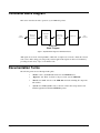
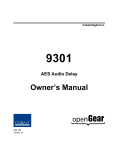
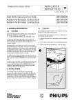
Functional Block Diagram
This section describes the basic operation of your ADM-188 product.
Audio Control:
8 pairs
16 channels
AES Decode
and Sample
Rate Conversion
Routing
Gain
Polarity
Audio Delay
(5.461 Seconds
Max)
AES Encode
8 pairs
16 channels
ADM-188
Block Diagram
Figure 1. Simplified Block Diagram of ADM-188 Functions
AES signals are received on the input BNCs. AES audio is sample rate converted to match the selected
clock source. AES routing, gain, and polarity are then applied. The signals are then stored in memory,
providing an audio delay of up to 5.461 milliseconds.
Documentation Terms
The following terms are used throughout this guide:
Page 8 of 23
•
“Frame” refers to the 8310 frame that houses the ADM-188 card.
•
“Operator” and “User” both refer to the person who uses the ADM-188.
•
“Board” and “Card” all refer to the ADM-188 card itself, including all components
and switches.
•
“System” and “Video system” refers to the mix of interconnected production and
terminal equipment in which the ADM-188 operates.
ADM-188 Owner’s Manual • (V 2.2)
Installation and Setup
In This Chapter
This chapter includes the following sections:
•
Static Discharge
•
Unpacking
•
Rear Module Installation (Optional)
•
Board Installation
•
Card Control and Settings
•
Factory Default Settings
Static Discharge
Whenever handling the card and other related equipment, please observe all static discharge
precautions as described in the following note:
Static discharge can cause serious damage to sensitive
semiconductor devices. Avoid handling circuit boards in high
static environments such as carpeted areas, and when wearing
synthetic fiber clothing. Always exercise proper grounding
precautions when working on circuit boards and related
equipment.
ESD
Susceptibility
Unpacking
Unpack each card you received from the shipping container, and check the contents against the packing
list to ensure that all items are included. If any items are missing or damaged, contact your sales
representative or Sierra Video Systems directly.
ADM-188 User Manual • (V 2.2)
Page 9 of 23
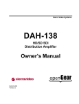
Rear Module Installation (Optional)
If you are installing the card in a 8310-C-BNC or 8310-BNC frame (one with a 100 BNC rear module
installed across the entire back plane), skip this section.
If you are installing the card into a slot with no rear module, you should have ordered and received one
of the following modules; RM-ADM-188-B or RM-ADM-188-C. You will need to install it in your
8310 frame before you can connect cables.
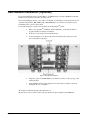
Use the following steps to install a rear module in an 8310 openGearTM frame:
1.
Refer to the openGearTM 8310 frame Owner’s Manual, to ensure that the frame is
properly installed according to instructions.
2.
On the rear of the 8310, locate the card frame slot.
3.
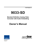
As shown in Figure 2, seat the bottom of the rear module in the seating slot at the
base of the frame’s back plane.
Figure 2. Rear Module Installation
4.
Align the top hole of the RM-ADM-188-C with the screw hole on the top edge of the
8310 back plane.
5.
Using a Phillips driver and the supplied screw, fasten the rear module to the 8310
back plane. Do not over tighten.
All modules are installed using the same method above.
The following section contains a table of the optional rear modules available for the ADM-188.
Page 10 of 23
ADM-188 Owner’s Manual • (V 2.2)
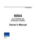
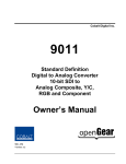
Rear Modules Available for ADM-188
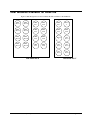
Figure 3. BNC Designations for the Card Rear Modules available for the ADM-188.
AES
OUT 1
AES
OUT 2
AES
IN 1
AES
IN 2
AES
IN 1
AES IN
2
AES
OUT 3
AES
OUT 4
AES
IN 3
AES
IN 4
AES
IN 3
AES
IN 4
AES
OUT 5
AES
OUT 6
AES
IN 5
AES
IN 6
AES IN
5
AES
OUT 7
AES
OUT 8
AES
IN 7
AES
IN 8
AES
OUT 2
AES
OUT 3
AES
OUT 4
AES
OUT 5
text
RM-ADM-188-B
ADM-188 User Manual • (V 2.2)
text
AES
OUT 1
RM-ADM-188-C
Page 11 of 23
Board Installation
Use the following steps to install the card in the openGearTM 8310 frame:
1.
Warning
Refer to the Owner’s Manual of the openGearTM 8310 frame to ensure that the frame
is properly installed according to instructions.
Heat and power distribution requirements within a frame may dictate
specific slot placement of cards. Cards with many heat-producing
components should be arranged to avoid areas of excess heat build-up,
particularly in frames using convection cooling.
2.
After selecting the desired frame installation slot, hold the card by the edges and
carefully align the card edges with the slots in the frame. Then, fully insert the card
into the frame until the rear connection plugs are properly seated on the midplane and
rear modules.
This completes the procedure for installing the card in the openGearTM 8310 frame.
Page 12 of 23
ADM-188 Owner’s Manual • (V 2.2)
Card Control and Status
Card Status
The card indicates the status of the input signal with the four blue LEDs labled with the different
supported formats (1080, 720, 625, 525), these LEDs correspond to AES Inputs 1-4. The four orange
LEDs labeled User 1-4 correspond to AES Inputs 5-8 respectively. When the card has locked to an
AES signal, a corresponding LED will be illuminated. When the card has not locked to an AES signal,
the card will search for a signal and the lights will cycle rapidly.
Menu Navigation
The card can be configured from a menu system built in to the front card edge. This provides an
intuitive and easy to use method for exploring and using the features of the card.
The menu is navigated by using the toggle switch and the two push buttons. The lower button is the
“Enter” button to enter a submenu, and the upper button is the “Exit” button to exit a submenu. Moving
the toggle switch up or down moves up or down in menu choices, and pressing the buttons moves in or
out of sub menus.
The menu LEDs will illuminate from top to bottom to indicate increasing depth in the menu.
Audio Submenu
Menu Structure
AES
Ch01- Src
Aud
Ch16 Gain
(x16) Pol
Tone
TG1-TG4 (x4)
Parameter Type
Output Source
Output Gain
Output Polarity
Tone Frequency
Output Source
Because the cards audio system functions like a router, each output can be sourced from any input
channel. This parameter lets you choose from the many different sources. Here is an explanation of the
different source names:
Source Name
Description
AeXX
Discrete AES channel XX (1 through 16)
TgX
Test Generator channel X (1 through 4)
Output Gain
The gain of each output is adjustable from +30 dB to –100 dB in 0.1 dB steps. After –100 dB gain is
set to –Inf, which means that output is present, but muted.
Output Polarity
If set to “Norm” output polarity is the same as input polarity, if set to “Inv” the output polarity is
inverted. This can be used to correct polarity errors in the input signals fed to the card.
ADM-188 User Manual • (V 2.2)
Page 13 of 23
Tone Frequency
This sets the frequency of the test tone for each of the four tone generators. Each of the four tone
generators TG1 – TG4 can be set to a different frequency, and are available as audio sources for the
embedded or AES audio outputs. The tones can range from 50Hz to 16kHz.
Display Submenu
Menu Structure
Disp H/V
BRGT
Parameter Type
Display Orientation
Display Brightness
Display Orientation
This parameter lets you change the orientation of the display. “Vert” makes the characters look correct
when the cards are mounted in a 2 RU frame like the 8310. “Horz” makes the characters look right in a
horizontal frame.
Display Brightness
This parameter allows you to set the standard output brightness of the menu display. It is a percentage
of maximum brightness.
Preset Submenu
Menu Structure
Prst
Slct
Save
Load
Fact
Parameter Type
Select Preset
Save Settings
Load Settings
Restore Factory Settings
Select Preset
Select from one of the five saved presets.
Save Settings
In this parameter, move the toggle switch up to save the settings to the card persistent storage.
Load Settings
In this parameter, move the toggle switch up to load the saved settings and make them active.
Restore Factory Settings
In this parameter, move the toggle switch up to make the factory default settings active, and make the
stored settings equal to the factory settings.
Information Submenu
Menu Structure
Info
+POW
-POW
SWR#
Page 14 of 23
Parameter Type
Positive Watts Consumed
Negative Watts Consumed
Software Release Number
ADM-188 Owner’s Manual • (V 2.2)
SWB#
Software Build Number
Positive Watts Consumed
A read only indication of power consumed by the card from the frames +12V rail.
Negative Watts Consumed
A read only indication of power consumed by the card from the frames +-7.5V rail.
Software Release Number
A read only indication of the software release number. A higher number is newer release of software.
Software Build Number
A read only indication of the software build number. Software build number is an internal indicator
used by Sierra engineers to differentiate different software builds.
Factory Default Settings
The factory default settings are as follows
1) The audio mapping is for each AES input to be routed to its respective AES output, for example
AES IN 1 to AES OUT 1.
2) Audio gain is set to 0dB and polarity is set to normal on all channels.
ADM-188 User Manual • (V 2.2)
Page 15 of 23
Remote Control
In This Chapter
This section provides a detailed explanation on using remote control functions with your card.
DashBoard Control System Software
The DashBoard Control System enables you to monitor and control openGearTM frames and controller
cards from a computer. The DashBoard software and manual can be downloaded from the Sierra Video
Systems website (www.sierravideo.com).
Using the Menus and Menu Descriptions
You must first install the DashBoard Control System software on your computer. Refer to the
DashBoard Owner’s Manual for software installation procedures and for using the DashBoard
interface.
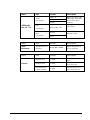
The following pages list the parameters from the menu tabs available in the DashBoard software when
connected to a ADM-188.
Menu
Item
Format
Description
Product
ADM-188
The product name
Sierra Video Systems
The manufacturer of the
product
Manufacturer
Card Info
(Read-only)
Software Release
Number
###
The release number of the
firmware in this card
Software Build
Date
###
The internal build number
of this software
Software Build
Time
###
The date and time the
software was created
+12 V Power Rail
#.## W
Positive Supply Power
-7.5 Power Rail
#.## W
Negative Supply Power
Video Input
Standard
############
Detected Video Standard
on SDI or Analog Input
Reference Standard
############
Detected standard of
selected reference.
############
Displays the Silicon Serial
Number of the card.
SSN
Page 16 of 23
ADM-188 Owner’s Manual • (V 2.2)
Menu
Item
Source
(per channel)
AES Audio
Out 1/2 - 7/8
Gain
(per channel)
Format
Description
AES 1-16
Silence
Selects the source for the
AES outputs. Each AES
source can be chosen
separately.
Range (-400) - 400
Gain applied to AES
audio output.
Tone Generator 1-4
Inverts the phase of the
AES audio output.
Phase
Normal
(per channel)
Invert
Menu
Item
Format
Description
Tone
Generator
Tone Generator 1-4
Frequency
Range 50Hz –16KHz
Selects the frequency of
the tone generated.
Menu
Item
Format
Description
Parameter Save
Confirm
Saves the parameters as
preset.
Parameter Load
Confirm
Loads parameters
previously saved.
Restart Parameters
to Factory Default
Confirm
Will load factory presets
and overwrite the save.
Presets
ADM-188 User Manual • (V 2.2)
Page 17 of 23
Technical Specifications
Category
Parameter
AES Audio
Input
AES Audio
Output
Standard
SMPTE 276M
Number of Inputs
8 unbalanced
Input Level
0.1 to 2.5V p-p (5V p-p tolerant)
Input Impedance
75Ω
Return Loss
> 12dB 100kHz to 6MHz
Equalization
Automatic to 1000m with Belden 1694A (or
equivalent) @ 48kHz AES signal
Sample Rate
48KHz
Standard
SMPTE 276M
Number of Outputs
8 unbalanced
Output Impedance
75Ω
Return Loss
> 30dB 100kHz to 6MHz
Resolution
Up to 24-bit
Sample Rate
48KHz
Number of Inputs
2 Terminating Frame Reference Inputs
Standards Supported
Signal Level
HD:
720p 24/25/29.97/30/50/59.94
1080i 25/29.97
1080p 23.98/24/25/29.97/30
1080p/sF 23.98/24
SD:
486i 29.97 NTSC, 575i 25 PAL
1Vp-p nominal
Signal
Analog video sync (black burst or tri-level)
Impedance
75Ω
Return Loss
> 30dB to 30MHz
Max DC on Ref Input
±1V
Total Power Consumption
< 5W
Warranty
Five Year Transferable
Reference
Video Input
Other
Specification
Specifications are subject to change without notice.
Page 18 of 23
ADM-188 Owner’s Manual • (V 2.2)
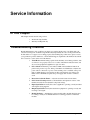
Service Information
In This Chapter
This chapter includes the following sections:
•
Troubleshooting Checklist
•
Warranty and Repair Policy
Troubleshooting Checklist
Routine maintenance to this openGear product is not required. In the event of problems with your
card, the following basic troubleshooting checklist may help identify the source of the problem. If the
module still does not appear to be working properly after checking all possible causes, please contact
your openGear products distributor, or the Technical Support department at the numbers listed under
the “Contact Us” section at the end of this manual.
1.
Visual Review Performing a quick visual check may reveal many problems, such
as connectors not properly seated or loose cables. Check the module, the frame, and
any associated peripheral equipment for signs of trouble.
2.
Power Check Check the power indicator LED on the distribution frame front
panel for the presence of power. If the power LED is not illuminated, verify that the
power cable is connected to a power source and that power is available at the power
main. Confirm that the power supplies are fully seated in their slots. If the power
LED is still not illuminated, replace the power supply with one that is verified to
work.
3.
Reseat the Card in the Frame Eject the card and reinsert it in the frame.
4.
Check Control Settings Refer to the Installation and Operation sections of the
manual and verify all user-adjustable component settings.
5.
Input Signal Status Verify that source equipment is operating correctly and that a
valid signal is being supplied.
6.
Output Signal Path Verify that destination equipment is operating correctly and
receiving a valid signal.
7.
Module Exchange Exchanging a suspect module with a module that is known to
be working correctly is an efficient method for localizing problems to individual
modules.
ADM-188 User Manual • (V 2.2)
Page 19 of 23
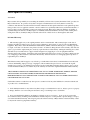
Sierra openGear Warranty
A. General
Buyer assumes all responsibility for ascertaining the suitability of Sierra Video Systems (hereinafter "SVS") products for
Buyer's intended use. No product sold by SVS is designed or manufactured for use in any manner or under any
conditions other than those described in SVS's instruction manuals and other printed material for each particular product.
If any product is used or applied in a manner or under conditions not specifically authorized by such written materials or
if any product is used by unqualified or improperly trained personnel, Buyer agrees that SVS shall have no liability of
any kind arising from such use, and Buyer agrees to indemnify and hold SVS harmless from any claims of third parties
arising from such use, and Buyer shall provide SVS with counsel of SVS's choice to defend against such claims.
B. Limited Warranty
1. This warranty applies only to the original purchaser and is non-transferable. This warranty begins on the date of
purchase and will be in effect for five (5) years for new equipment or and for three (3) years for "Factory Refurbished"
equipment. Buyer must obtain a Return Material Authorization ("RMA") number from SVS prior to returning a product
for repair. If, in SVS' sole discretion, the product is found to be defective during the term of this warranty, SVS will at its
option: (a) provide free replacement parts, and/or (b) repair the unit at an SVS facility. During the warranty period, SVS
will make every reasonable effort to support critical emergencies by supplying no-cost loan equipment while the
defective unit is being repaired. SVS will provide replacement parts and/or factory service at no charge. Buyer bears the
cost of shipping products returned to SVS under this warranty. SVS will bear the cost of shipping repaired products or
replacement parts to the Buyer.
This limited warranty shall not apply to any of SVS's goods which have been altered or which shall have been subjected
to misuse, mishandling, improper storage or negligence. The aforementioned provisions do not extend the original
warranty period of any goods which have been replaced by SVS. This limited warranty shall not apply to any goods not
of SVS's manufacture, Buyer to be entitled only to the warranty set forth in the original manufacturer's limited warranty.
THIS LIMITED WARRANTY IS EXPRESSED IN LIEU OF ALL OTHER WARRANTIES, EXPRESS, IMPLIED
OR STATUTORY, INCLUDING WITHOUT LIMITATION THE IMPLIED WARRANTIES OF
MERCHANTABILITY AND OF FITNESS FOR A PARTICULAR PURPOSE, AND ALL OTHER OBLIGATIONS
OR LIABILITIES ON SVS'S PART.
SVS neither assumes nor authorizes any other person to assume for SVS any other liabilities in connection with the sale
of products of its own manufacture.
2. SVS's liability hereunder on any claim of any kind, except as set forth herein for any loss, injury to person or property
or damage, shall in no case exceed the price allocable to the goods which give rise to such claim.
3. In no event shall SVS be liable for any damages or injuries to person or property if any goods do not meet the
above limited warranty, including, without limitation, incidental expenses or consequential or special damages, except as
set forth in such limited warranty. The foregoing states the exclusive remedy of Buyer and the exclusive liability of SVS
for any breach of the foregoing limited warranty.
Page 20 of 23
ADM-188 Owner’s Manual • (V 2.2)
C. Cancellation
Except as provided in paragraph B immediately above, all sales are final, and Buyer may cancel this order or return
products only upon written consent of SVS.
D. General
A.
In the event of a breach of any of the terms hereof, the non-breaching party shall be entitled to recover all of its
costs, fees, and expenses, including, without limitation, reasonable attorney's fees, from the breach party incurred as a
result of such breach, regardless of whether or not a suit is actually filed to enforce the terms hereof.
B.
The provision hereof shall be governed by the laws of the State of California (excluding its choice of law
provisions).
C.
The headings are for convenience only and do not limit or amplify the terms and provisions hereof.
D.
In case any one or more of the provisions set forth herein shall be held to be invalid, illegal, or unenforceable in
any respect, the validity, legality, and enforceability of the remaining provisions contained herein shall not in any way be
affected or impaired thereby.
E.
No waiver, alteration, or modification of any of the provisions hereof shall be binding unless in writing and
signed by an authorized Officer of SVS.
NOTE:
All products returned to SVS for service must have prior approval. Return authorization requests may be obtained from
your SVS dealer.
ADM-188 User Manual • (V 2.2)
Page 21 of 23
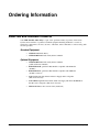
Ordering Information
ADM-188 and Related Products
Your ADM-188 AES Audio Delay is a part of the openGear family of products. Sierra Video
Systems offers a full line of openGear terminal equipment including distribution, conversion,
monitoring, synchronizers, encoders, decoders, embedders, and de-embedders, as well as analog audio
and video products.
Standard Equipment
•
ADM-188 AES Audio Delay
•
ADM-188-OM AES Audio Delay Owner’s Manual
Optional Equipment
Page 22 of 23
•
ADM-188-OM AES Audio Delay Owner’s Manual
(additional Owner’s Manual)
•
RM-ADM-188-B openGearTM Rear Module compatible with ADM-188
(10 BNC)
•
RM-ADM-188-C openGearTM Rear Module compatible with ADM-188
(16 BNC connector)
•
8310-C Digital Products Frame and Power Supply with Cooling Fans
(2RU, holds 10 cards)
•
8310-C-BNC Digital Products Frame and Power Supply with fixed 100-BNC Rear
Module and Cooling Fans. (2RU, holds 10 cards)
•
MFC-8310-N Network Controller Card (Additional)
ADM-188 Owner’s Manual • (V 2.2)
Contact Us
Contact Sierra Video Systems
PHONE
E-MAIL
POSTAL
SERVICE
General Business Office
and Technical Support
530.478.1000
Fax
530.478.1105
General Information
[email protected]
Sales Information
[email protected]
Sierra Video Systems
P.O. Box 2462
Grass Valley, CA 95945 USA
Visit us at the Sierra Video Systems website.
http://www.sierravideo.com
•
Online catalog
•
Related products and full product lines
•
Trade show information
•
Dealer information
•
Sierra Video Systems news
ADM-188 User Manual • (V 2.2)
Page 23 of 23