1
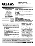
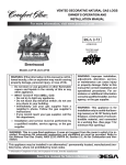
VENTED DECORATIVE NATURAL GAS LOGS
OWNER’S OPERATION AND
INSTALLATION MANUAL
For more information, visit www.desatech.com
Vanguard Burner Models VVSR18, VVSR24, VVDR18, VVDR24, and VVDR30
For Use with Log Sets:
Hanover Round Oak Log Models VSLR18 and VSLR24
Kingston Split Oak Log Models VDLCR18, VDLCR24 (Shown), and VDLCR30
FMI Burner Models FVSR18, FVSR24, FVDR18, FVDR24, and FVDR30
For Use with Log Sets:
Arlington Round Oak Log Models FSLR18 and FSLR24
Manchester Split Oak Log Models FDLCR18, FDLCR24 and FDLCR30
Comfort Glow Oxford Oak Log Set and Burner Models:
CVSR18 and CVSR24
Comfort Glow Amherst Oak Log Set and Burner Models:
CPVSR18 and CPVSR24
Comfort Glow Berkshire Oak Log Set and Burner Models:
CVDR18, CVDR24, and CVDR30
Comfort Glow Shenandoah Oak Log Set and Burner Models:
LBFL18 and LBFL24
Comfort Glow Conventry Oak Log Set and Burner Models:
LVDR18, LVDR24 and LVDR30
APPROVED
Comfort Glow Mendocino Oak Log Set and Burner Models:
BFLT18 and BFLT24
Comfort Glow Malibu Drift Log Set and Burner Models: MD18 and MD24
RGA 2-72
WARNING: If the information in this manual is not
followed exactly, a fire or explosion may result causing property damage, personal injury, or loss of life.
— Do not store or use gasoline or other flammable
vapors and liquids in the vicinity of this or any
other appliance.
— WHAT TO DO IF YOU SMELL GAS
• Do not try to light any appliance.
• Do not touch any electrical switch; do not use
any phone in your building.
• Immediately call your gas supplier from a
neighbor’s phone. Follow the gas supplier’s
instructions.
• If you cannot reach your gas supplier, call the
fire department.
— Installation and service must be performed by a
qualified installer, service agency, or the gas
supplier.
TESTED AND
LISTED BY
WARNING: Improper installation,
adjustment, alteration, service, or
maintenance can cause injury or
property damage. Refer to this
manual for correct installation and
operational procedures. For assistance or additional information consult a qualified installer, service
agency, or the gas supplier.
WARNING: This appliance is for
installation only in a solid-fuel burning masonry or UL127 factory-built
fireplace, constructed of noncombustible material, and connected
to a working flue. (See page 7 for
minimum flue opening.)
WARNING: This is a gas-fired appliance. It uses air (oxygen) from the room in which it is installed.
Provisions for adequate combustion and ventilation air must be provided. Refer to the National
Fuel Gas Codes, ANSI Z233.1/NFPA 54, Section 5.3, Air for Combustion and Ventilation.
This appliance may be installed in an aftermarket,* permanently located, manufactured
(mobile) home, where not prohibited by local codes.
* Aftermarket: Completion of sale, not for purpose of resale, from the manufacturer
Save this manual for future reference.
2
TABLE OF CONTENTS
SAFETY INFORMATION
TABLE OF CONTENTS
SAFETY INFORMATION ............................................................ 2
SERVICE HINTS ........................................................................ 11
PRODUCT IDENTIFICATION ..................................................... 3
TECHNICAL SERVICE .............................................................. 11
LOCAL CODES ........................................................................... 3
REPLACEMENT PARTS ........................................................... 11
UNPACKING ............................................................................... 3
TROUBLESHOOTING .............................................................. 12
OPTIONAL PRODUCT FEATURES ........................................... 3
ACCESSORIES ........................................................................ 15
INSTALLATION ........................................................................... 4
ILLUSTRATED PARTS BREAKDOWN AND PARTS LIST ....... 16
OPERATING APPLIANCE ........................................................ 10
OWNER’S REGISTRATION FORM ........................................ ..29
CLEANING AND MAINTENANCE ............................................. 11
WARRANTY INFORMATION ...................................... Back Cover
SAFETY INFORMATION
WARNING ICON
G 001
2.
WARNINGS
WARNING: This product contains and/or generates
chemicals known to the State of California to cause
cancer or birth defects, or other reproductive harm.
WARNING: Keep flue open when operating unit.
IMPORTANT: Read this owner’s manual carefully and
completely before trying to assemble, operate, or service this log set. Improper use of this log set can cause
serious injury or death from burns, fire, explosion,
electrical shock, and carbon monoxide poisoning.
DANGER: Carbon monoxide poisoning may lead
to death!
Carbon Monoxide Poisoning: Early signs of carbon monoxide
poisoning resemble the flu, with headaches, dizziness, or nausea. If
you have these signs, the log set may not be working properly. Get
fresh air at once! Have log set serviced. Some people are more
affected by carbon monoxide than others. These include pregnant
women, people with heart or lung disease or anemia, those under the
influence of alcohol, and those at high altitudes.
Natural Gas: Natural gas is odorless. An odor-making agent is
added to the gas. The odor helps you detect a gas leak. However, the
odor added to the gas can fade. Gas may be present even though no
odor exists.
Make certain you read and understand all warnings. Keep this manual
for reference. It is your guide to safe and proper operation of this log set.
WARNING: Any change to this log set or its
controls can be dangerous.
1.
This appliance, as supplied, is only for use with the type of gas
indicated on the rating plate. This appliance is convertible for use
with propane/LP, using the GA9050A or GA9150A pilot kit.
If you smell gas
• shut off gas supply
• do not try to light any appliance
• do not touch any electrical switch; do not use any phone in
your building
• immediately call your gas supplier from a neighbor’s phone.
Follow the gas supplier’s instructions
• if you cannot reach your gas supplier, call the fire department
3. Never install the log set
• in a recreational vehicle
• where curtains, furniture, clothing, or other flammable objects are less than 42 inches from the front, top, or sides of
the log set
• in high traffic areas
• in windy or drafty areas
4. Before installing in a solid fuel burning fireplace, the chimney
flue and firebox must be cleaned of soot, creosote, ashes and
loose paint by a qualified chimney cleaner. Creosote will ignite if highly heated. Inspect chimney flue for damage. If damaged, repair flue before operating heater.
5. You must operate this log set with a fireplace screen in place.
Make sure fireplace screen is closed before running log set.
6. This log set is designed to be smokeless. If logs ever appear to
smoke, turn off appliance and call a qualified service person.
Note: During initial operation, slight smoking could occur due
to log curing and the burning of manufacturing residues. You
may wish to add more ventilation by opening a window.
7. To reduce the creation of soot, follow the instructions in Cleaning and Maintenance, page 11.
8. Do not allow fans to blow directly into the fireplace. Avoid
any drafts that alter burner flame patterns. Ceiling fans can
create drafts that alter burner flame patterns. Altered burner
patterns can increase sooting.
9. Do not use a blower insert, heat exchanger insert or other accessory not approved for use with this log set.
10. The installation and provisions for combustion and ventilation
air must conform with the National Fuel Gas Code, ANSI Z233.1/
NFPA 54, Section 5.3, Air for Combustion and Ventilation.
For more information, visit www.desatech.com
901265-01K
SAFETY INFORMATION
PRODUCT IDENTIFICATION
LOCAL CODES
UNPACKING
OPTIONAL PRODUCT FEATURES
SAFETY INFORMATION
3
3
LOCAL CODES
Continued
11. Do not run log set
• where flammable liquids or vapors are used or stored
• under dusty conditions
12. Do not burn solid fuel in the fireplace after installing the log set.
Do not use this log set to cook food or burn paper or other objects.
13. Log set becomes very hot when in use. Keep children and adults
away from hot surface to avoid burns or clothing ignition. Log
set will remain hot for a time after shutdown. Allow surface to
cool before touching.
14. Carefully supervise young children when they are in the room
with log set.
15. Do not use appliance if any part has been exposed to or under
water. Immediately call a qualified service technician to inspect
the room appliance and to replace any part of the control system (if using GA9050A or GA9150A) and any gas control which
has been under water.
16. To help prevent breakage, new logs must be broken-in (see
Curing Logs page 10).
17. Turn log set off and let cool before servicing, installing, or repairing. Only a qualified service person should install, service, or repair log set.
18. Provide adequate clearances around air openings.
PRODUCT IDENTIFICATION
Grate Steps
Grate
Install and use log set with care. Follow all local codes. In the absence
of local codes, use the latest edition of The National Fuel Gas Code
ANSI Z223.1/NFPA 54*.
*Available from:
American National Standards Institute, Inc.
1430 Broadway
New York, NY 10018
National Fire Protection Association, Inc.
Batterymarch Park
Quincy, MA 02269
UNPACKING
CAUTION: Do not remove the data plates from the
burner pan. The data plates contain important product information.
1.
2.
3.
Remove logs, hearth kit, pan materials, and hardware from carton.
Remove all protective packaging applied to logs and base for
shipment.
Check all items for any shipping damage. If damaged, promptly
inform dealer where you bought the product.
OPTIONAL PRODUCT
FEATURES
ON/OFF SAFETY VALVE/PILOT KIT AND
PROPANE/LP CONVERSION
An optional valve/safety pilot kit with a piezo ignitor is available for
this appliance. This system requires no matches, batteries, or other
sources to light. You must use this optional system for LP conversion. See Accessories, page 15.
REMOTE CONTROL READY (MILLIVOLT)
SAFETY VALVE/PILOT KIT
Burner
Pan
An optional millivolt valve/safety pilot kit with a piezo ignitor is
available for this appliance. This system requires no matches, batteries,
or other sources to light. This system may be connected to a wall switch
or hand-held wireless remote control. See Accessories, page 15.
Burner
Clamp
Burner
Manifold
Burner Inlet
Fitting
Figure 1 - Product Identification (Dual Burner Shown)
Hearth Kit Model _________________________
Serial Number ___________________________
Log Set Model ___________________________
REMOTE CONTROL ACCESSORIES
There is an optional hand-held ON/OFF remote control that can be
purchased separately for this log set. You must use the millivolt
valve/safety pilot kit to use remote accessories with this appliance.
See Accessories, page 15.
A wall switch is also available for this appliance. You must use the
millivolt valve/safety pilot kit to use the wall switch with this
appliance. See Accessories, page 15.
For more information, visit www.desatech.com
901265-01K
4
INSTALLATION
Flue Opening Specifications
Check Gas Type
Venting Specifications for Installation
INSTALLATION
CAUTION: Do not remove the data plates attached
to the burner pan. The data plates contain important
warranty information.
WARNING: Before installing in a solid fuel burning
fireplace, the chimney flue and firebox must be cleaned
of soot, creosote, ashes and loose paint by a qualified
chimney cleaner. Creosote will ignite if highly heated.
A dirty chimney flue may create and distribute soot
within the house. Inspect chimney flue for damage. If
damaged, repair flue before operating heater.
NOTICE: Installation, service, and repair of this appliance must be performed by a qualified installer,
service agency, company or gas supplier experienced with this type of gas appliance. Only factory
authorized components listed in these instructions
may be used in accordance with the manufacturer’s
instructions and all codes and requirements of the
authority having jurisdiction. Any modifications to
this kit, or use of unauthorized components or accessory items will void the manufacturer’s warranty, and
may result in a hazardous condition.
FLUE OPENING SPECIFICATIONS
Note: This vented appliance must be installed only in a solid-fuel
burning fireplace with a working flue and constructed of noncombustible material.
The charts in Figure 2 indicate technical information regarding the
installation of your gas log set. Please make sure that all of the
specifications shown are applicable before installation is attempted.
The fireplace must include a working flue and venting system with
the minimum openings shown in the Figure 2.
MODEL
BURNER
DESCRIPTION
VVSR18
FVSR18
18" Single
VVSR24
FVSR24
24" Single
60,000
50,000
8" dia.
VVDR18
FVDR18
MD18
18" Dual
55,000
45,000
8" dia.
VVDR24
FVDR24
MD24
24" Dual
65,000
55,000
8" dia.
VVDR30
FVDR30
30" Dual
70,000
60,000
8" dia.
LBFL18
BFLT18
18" Triple
65,000
55,000
8" dia.
LBFL24
BFLT24
24" Triple
70,000
60,000
8" dia.
MINIMUM FIREBOX SIZES
FRONT
WIDTH*
BACK
WIDTH**
DEPTH
HEIGHT
18DR/SR
MD18
28"
16"
14"
18"
24DR/SR
MD24
29 3/4"
17"
15 1/2"
18"
30DR
36"
27"
18"
18"
BFL18
28"
16"
15 1/2"
18"
BFL24
30"
22"
15 1/2"
18"
MODEL
*Add 6" if safety valve/pilot is used
**At depth indicated
FUEL INLET PRESSURE
SPECIFICATIONS (W.C.)
Min.
Max.
CHECK GAS TYPE
Use only natural gas. If your gas supply is not natural gas, you must
install ON/OFF Safety Valve/Pilot Kit (see Accessories, page 15).
Call dealer where you bought log set.
If the fireplace does not have a gas supply shutoff valve, one must
be installed.
VENTING SPECIFICATIONS FOR
INSTALLATION
The fireplace chimney flue and vent must be drafting properly. To
check the vent for proper drafting: Light a tightly rolled newspaper
on one end and place it at the inside front edge of the fireplace.
Observe the smoke and be sure the vent is properly drawing it up the
chimney. If the smoke spills out into the room, extinguish the flame
and remove any obstruction until proper venting is achieved.
The chimney flue must remain open a minimum of 3" at all times
during the operation of this log set.
Btu Input
Btu Input
Minimum
Natural Gas Propane/LP Vent Opening
Gas
50,000
40,000
8" dia.
LOG
SIZE
NG
5.5"
10.5"
LP
11"
13"
BURNER ORIFICE
NATURAL
IN.
NUM.
PROPANE/LP
IN.
NUM.
18SR/DR
MD18/18SR/DR
.120
31
.073
49
24SR/DR/BFL18
MD24/24SR/DR/BFL18
.129
30
.086
44
30DR/BFL24
.1405
28
.089
43
Figure 2 - Technical Information Charts
For more information, visit www.desatech.com
901265-01K
INSTALLATION
Installing Damper Clamp
Connecting to Gas Supply
5
5
INSTALLATION
Continued
INSTALLING DAMPER CLAMP
Secure the damper stop clamp provided to the leading edge of the
damper as shown in Figure 3. If for any reason this clamp doesn't
work on your fireplace, another suitable clamp or permanent stop
must be installed, or the damper blade must be cut or removed.
Damper Clamp
Damper
Clamp
WARNING: Use pipe joint sealant that is resistant
to liquid petroleum (LP) gas.
Damper
Masonry Fireplace
IMPORTANT: Install equipment shutoff valve in an accessible
location. The equipment shutoff valve is for turning on or shutting
off the gas to the appliance.
Apply pipe joint sealant lightly to male NPT threads. This will
prevent excess sealant from going into pipe. Excess sealant in pipe
could result in a clogged burner injector.
Damper
Damper
Installation must include a equipment shutoff valve, union, and
plugged 1/8" NPT tap. Locate NPT tap within reach for test gauge
hook up. NPT tap must be upstream from log set (see Figure 4).
Manufactured
Fireplace
Figure 3 - Attaching Damper Clamp
CONNECTING TO GAS SUPPLY
We recommend that you install a sediment trap in supply line as
shown in Figure 4. Locate sediment trap where it is within reach for
cleaning. Install in piping system between fuel supply and heater.
Locate sediment trap where trapped matter is not likely to freeze. A
sediment trap traps moisture and contaminants. This keeps them
from going into log set controls. If sediment trap is not installed or
is installed wrong, log set may not run properly.
Approved Flexible Gas Hose
(if allowed by local codes)
CSA Design-Certified
Equipment Shutoff
Valve With 1/8" NPT
Tap*
WARNING: A qualified service person must connect log set to gas supply. Follow all local codes.
Installation Items Needed
Before installing log set, make sure you have the items listed below.
• piping (check local codes)
• sealant (resistant to Propane/LP gas)
• equipment shutoff valve
• test gauge connection
• adjustable (crescent) wrench or pliers
• sediment trap
• tee joint
• pipe wrench
CAUTION: Use only new, black iron or steel pipe.
Internally-tinned copper tubing may be used in certain
areas. Check your local codes. Use pipe of 1/2" diameter or greater to allow proper gas volume to log set. If
pipe is too small, undue loss of volume will occur.
From Gas Meter
(5" W.C.** to 10.5"
W.C. Pressure)
3" Minimum
Cap
Pipe Nipple Tee Joint
Figure 4 - Gas Connection
* Purchase the optional CSA design-certified equipment shutoff
valve from your dealer. See Accessories, page 15.
** Minimum inlet pressure for purpose of input adjustment.
For more information, visit www.desatech.com
901265-01K
Sediment Trap
6
INSTALLATION
Checking Gas Connections
Hearth Kit Assembly and Installation
INSTALLATION
Continued
CHECKING GAS CONNECTIONS
WARNING: Test all gas piping and connections,
internal and external to unit, for leaks after installing
or servicing. Correct all leaks at once.
HEARTH KIT ASSEMBLY AND INSTALLATION
Kit Assembly - Single and Dual-Flame Only
1.
NOTICE: Triple-burner models CBL18/24 or BFLT18/24
come preassembled with gas inlet on right side of
burner pan. DO NOT attempt to reposition burner on
triple-burner models. If your fireplace supply is on the
left side, a longer 3/8" flex line should be purchased and
routed behind burner pan and away from flame area.
WARNING: Never use an open flame to check for
a leak. Apply a noncorrosive leak detection fluid to
all joints. Bubbles forming show a leak. Correct all
leaks at once.
Pressure Testing Gas Supply Piping System
Test Pressures In Excess Of 1/2 PSIG (3.5 kPa)
1. Disconnect log set and its individual equipment shutoff valve
from gas supply piping system.
2. Cap off open end of gas pipe where equipment shutoff valve
was connected.
3. Pressurize supply piping system by either using compressed
air or opening main gas valve located on or near gas meter.
4. Check all joints of gas supply piping system. Apply noncorrosive
leak detection fluid to gas joints. Bubbles forming show a leak.
5. Correct all leaks at once.
6. Reconnect log set and equipment shutoff valve to gas supply.
Check reconnected fittings for leaks.
Test Pressures Equal To or Less Than 1/2 PSIG (3.5 kPa)
1. Close equipment shutoff valve (see Figure 5).
2. Pressurize supply piping system by either using compressed
air or opening main gas valve located on or near gas meter.
3. Check all joints from gas meter to equipment shutoff valve
(see Figure 5). Apply noncorrosive leak detection fluid to gas
joints. Bubbles forming show a leak.
4. Correct all leaks at once.
Equipment
Shutoff Valve
Gas Meter
Determine which side the gas line will be coming into the fireplace.
2.
3.
4.
5.
Using a hammer and screw driver, remove knockout plug from
the side of the pan that corresponds to the gas line (see Figure 6).
Unscrew burner inlet fitting from burner manifold.
Place burner manifold in pan with threaded opening facing
open knockout plug.
Using thread sealant (resistant to the action of propane/LP
gas) on larger end of fitting, screw the burner inlet fitting
through hole and into burner manifold (see Figure 6). Tighten
using a wrench. If using propane/LP gas, see Propane/LP
Gas Conversion, page 8.
Nut
Burner Manifold
Knockout
Plugs
Knockout
Plugs
Burner Pan
(Front)
Burner Pan
(Front)
Burner Inlet
Fitting
SINGLE-BURNER
Screw
Burner Inlet
Fitting
DUAL-FLAME
Burner
Manifold
Front Burner
Burner Pan
(Front)
Figure 5 - Checking Gas Joints
Burner Clamp
TRIPLE-BURNER
Gas Connection
Must Be On Right
Side For Triple
Burner
Burner Inlet
Fitting
Figure 6 - Installing Burner
For more information, visit www.desatech.com
901265-01K
INSTALLATION
Hearth Kit Assembly and Installation (Cont.)
Optional GA9050A ON/OFF Safety Valve/Pilot Kit Assembly
7
7
INSTALLATION
Continued
6.
7.
Using burner clamp, screw, and nut provided, assemble clamp
to pan (“U” style and triple burners only). This will hold the
burner manifold in place.
If using optional GA9050A kit, go to Optional GA9050A On/
Off Safety Valve/Pilot Kit section for installation instructions.
If using optional GA9150A kit, follow instructions included
with kit for installation and operation.
2.
3.
4.
4.
5.
6.
Installation and Gas Connection
1.
3.
Place the burner pan assembly in the center of the fireplace
floor. Make sure the front of pan faces forward.
Thread the gas supply fitting to the fireplace gas supply pipe.
Use thread sealant.
Install adapter fitting onto the burner inlet fitting using
thread sealant on male threads of burner inlet fitting (see
Figure 7). Adjust to most convenient position.
Install the gas connector tube to the gas supply fitting. Carefully shape tube to attach to adapter fitting. Be careful not to
cause kinks in tube.
Gas Connector
Tube
Burner Pan
Assembly (Facing
Front of Fireplace)
Adapter
Fitting
7.
8.
Install the inlet fitting into the inlet opening of the gas control
valve (see Figure 10). Use thread sealant on the male pipe
threads.
Place the burner pan assembly in the center of the fireplace
floor. Make sure the front of pan faces forward.
Thread the gas supply fitting to the fireplace gas supply pipe.
Adjust to most convenient position.
Install the gas connector tube to the gas supply fitting. Carefully
shape tube to attach to adapter fitting. Be careful not to cause
kinks in tube.
Test for leaks following instructions under Testing Burner for
Leaks, page 9.
Retighten and adjust the location of the gas control as necessary.
The gas control should be level, with the control rod to the front.
Burner Inlet Fitting
Gas Control
Valve
Burner Pan
Assembly
Figure 8 - Installing Gas Control Valve
Control Rod
Thermocouple and Line
Figure 7 - Connecting Gas to Appliance
OPTIONAL GA9050A ON/OFF SAFETY
VALVE/PILOT KIT ASSEMBLY
Pilot and Line
For additional convenience and safety, or for propane/LP conversion, an optional ON/OFF safety valve/pilot kit is available. See
Accessories, page 15.
Gas Control Valve
Figure 9 - Gas Control Valve with Thermocouple and Pilot
WARNING: You must use a ON/OFF safety valve/
pilot kit for propane/LP conversion.
Gas
Connector
Tube
Natural Gas Installation
1.
2.
Thread the gas control valve onto the burner inlet fitting (see
Figure 8). Use thread sealant on the male threads of the burner
inlet fitting. Hold the burner inlet fitting with a wrench to prevent overtightening the connection to the burner. Make sure
the control rod is facing the front (see Figure 8).
Attach the pilot gas line to the pilot outlet of the gas control valve
and tighten. Connect the thermocouple to the rear of the gas control valve. See Figure 9. Do not overtighten. If using propane/LP
gas, see Changing Pilot Orifice, page 8.
Gas Control
Valve
Inlet
Opening
Figure 10 - Installing Inlet Fitting and Gas Connector Tube
For more information, visit www.desatech.com
901265-01K
Gas Inlet
Fitting
8
INSTALLATION
Optional GA9050A ON/OFF Safety Valve/Pilot Kit Assembly (Cont.)
INSTALLATION
Continued
9. Install cover to burner pan using screws provided.
10. Install thermocouple, pilot, and ignitor onto valve cover as
shown in Figure 11. Use the provided screws.
11. Push the control rod extension onto the “D” shaped control
rod through the center hole in the cover.
12. Install the position decal and control knob making sure to align
the marks with the correct stop positions of the gas control.
4.
Using thread sealant (resistant to the action of propane/LP gas) on
larger end of fitting, screw the burner inlet fitting through hole
and into burner manifold (see Figure 13). Tighten using a wrench.
5 . Follow steps 1 through 12 under Natural Gas Installation, pages
7 and 8.
Injector for
Natural Gas
Injector for
Propane/LP Gas
Thermocouple
Screw
NATURAL
GAS FITTING
Ignitor
PROPANE/LP
GAS FITTING
Figure 12 - Burner Inlet Fittings with Injectors
Pilot
Burner Inlet
Fitting for
Natural Gas
Valve Cover
Piezo Ignitor
Control
Knob
Control Rod
Extension
Figure 13 - Remove Burner Inlet Fitting
Figure 11 - Installing Cover, Control Knob, and Piezo Ignitor
Propane/LP Gas Conversion
To convert to propane/LP gas, the burner inlet fitting and pilot orifice
must be replaced. The propane/LP burner inlet fitting is supplied with
the orifice installed for a 24" log set. If you have an 18" or 30" set, you
must change this orifice also. See Figure 1, page 3 for product
identification.
Burner Inlet Fitting
1. Remove the burner inlet fitting from the burner pan assembly.
DO NOT remove the orifice from this fitting. The propane/LP
burner inlet fitting is included in the hardware kit (see Figure 12).
2. Be sure to use the correct orifice for your appliance. The hardware kit included with this appliance contains two orifices with
a cone-like shape. If you have an 18" set, the orifice for the
burner inlet fitting is red; for a 30" set, it is black. If you have
a 24" log set, the orifice is already installed inside the fitting.
3. For an 18" or 30" set, use a 10mm socket or nut driver to remove the orifice from the propane/LP burner inlet fitting.
Choose the correct orifice for your log set size and install in
place of the orifice you just removed.
Changing Pilot Orifice
The pilot is provided with a natural gas orifice installed. For
propane/LP gas you must remove it and replace it with an propane/
LP orifice. The accessory hardware kit contains an propane/LP
orifice with a red stripe for converting the pilot.
1. Gently loosen and remove the pilot line connection from the
bracket (see Figure 14).
2. Replace the injector (see Figure 14) with the propane/LP pilot
injector with the red stripe.
3. Replace and tighten the pilot line to the bracket.
4. Continue with step 3 under Natural Gas Installation, pages 7
and 8.
Pilot Injector
Figure 14 - Installing Propane/LP Pilot Orifice
For more information, visit www.desatech.com
901265-01K
INSTALLATION
Testing Burner for Leaks
Adding Pan Material
Installing the Grate and Logs
9
9
INSTALLATION
Continued
TESTING BURNER FOR LEAKS
1.
Generously apply noncorrosive leak detection fluid to all
connections.
WARNING: Never check for gas leaks with
open flame.
2.
3.
4.
5.
Light the burner with the shutoff valve no more than half open
and holding a match slightly in front of the pan (see Lighting
Instructions, page 10).
Inspect all connections for bubbles, raw gas odor, or flame
from any area other than the burner (leaks). If leaks are detected, shut off the gas valve immediately. Tighten, or reassemble the loose connection(s) using pipe joint compound until
burner system is leak free.
When the burner is tested and leak free, observe the individual
tongues of flame on the burner. Note: The burner design includes more ports on the outside of the bar. Make sure that all
ports are clear and producing flame evenly across the burner. If
any ports appear blocked, clear them by removing the burner
manifold and reaming the ports with a modified paper clip or
other suitable tool.
When finished testing, turn the gas shutoff valve OFF to extinguish all flames.
3.
4.
5.
Place the back log on the grate onto the grate steps (see
Figure 16).
Place the front log(s) on the grate and slide forward against
the front bars on the grate (see Figure 16).
Place the smaller top logs onto the bottom logs (see Figure 17).
Leave as much open space between logs as possible to minimize flame impingement and sooting. Note: Logs may chip if
they are handled roughly or if hit together while being placed.
Kingston Split Oak Logs
Hanover Round Oak Logs
Figure 16 - Installing Front and Back Logs (Number and style of
your logs may vary)
ADDING PAN MATERIAL
1.
2.
Open the bag of ash bed material (vermiculite) and spread it
evenly across the burner pan to the top. You may overflow the
front and sides of the pan to cover the entire pan and connecting hardware. Do not cover GA9050A or GA9150A valve.
Open the glowing embers and evenly cover the ash bed material (vermiculite) in the burner pan.
INSTALLING THE GRATE AND LOGS
1.
2.
Place the grate over the burner pan where the two outer horizontal supports on the grate fit into the two pan positioning
notches in the rear vertical edge of the pan.
Slide the two rear log grate steps over the two outer horizontal
supports on the grate as shown in Figure 15.
Kingston Split Oak Logs
Figure 17 - Placement of Top Logs
Grate Steps
Grate
Figure 15 - Installing Grate (Pan Material Not Shown)
For more information, visit www.desatech.com
901265-01K
Malibu Drift Logs
10
OPERATING APPLIANCE
For Your Safety Read Before Lighting
Lighting Instructions
Gas Shutoff Valve Operation
Curing Logs
Operating Instructions for GA9050A
OPERATING APPLIANCE
FOR YOUR SAFETY
READ BEFORE LIGHTING
WARNING: Keep flue open when operating unit.
WARNING: If you do not follow these instructions
exactly, a fire or explosion may result causing property damage, personal injury or loss of life.
BEFORE LIGHTING smell all around the appliance area for
gas. Be sure to smell next to the floor because some gas is heavier
than air and will settle on the floor.
WHAT TO DO IF YOU SMELL GAS
• Do not try to light any appliance.
• Do not touch any electric switch; do not use any phone in
your building.
• Immediately call your gas supplier from a neighbor’s phone.
Follow the gas supplier’s instructions.
• If you cannot reach your gas supplier, call the fire department.
LIGHTING
INSTRUCTIONS
1.
2.
3.
4.
5.
STOP! Read the safety information, above.
Turn the gas shutoff valve to OFF.
Wait five (5) minutes to clear out any gas. If you then smell
gas STOP! Follow the safety information above. If you don't
smell gas, go on to the next step.
Light a match and lay it on top of the pan material about
2" from the end of the supply side of the pan
Slowly turn the gas shutoff valve ON until the burner ignites. If the burner doesn’t ignite within 10 seconds with
the match burning, turn the shutoff valve OFF and repeat
steps 1 through 4 again.
CURING
LOGS
During the 2-3 hour appliance break-in period, you may detect
an odor from the appliance as the various paints and compounds used in the manufacturing of this log set cure. This is a
normal and temporary situation that is not cause for alarm.
However, you may want to provide extra ventilation to the room
during this time.
To ensure proper curing of the logs:
• Ignite a 2" flame and maintain it for 1 hour.
• Burn the logs in consecutive 1 hour periods raising the flame
an additional 2" to full flame height for a total of three hours.
OPERATING INSTRUCTIONS
FOR GA9050A
Note: Operation instructions for GA9150A Remote Ready
Valve/Pilot Kit will be included with the kit.
1. STOP! Read the safety information, column one this page.
2. Make sure equipment shutoff valve is fully open.
to the
3. Press in and turn control knob clockwise
OFF position.
4. Wait five (5) minutes to clear out any gas. Then smell for
gas around log set and near floor. If you smell gas, STOP!
Refer to the National Fuel Gas Codes, ANSI Z233.1/NFPA
54, Section 5.3, Air for Combustion and Ventilation. If you
don’t smell gas, go to the next step.
5. Turn control knob counterclockwise
to the PILOT
position and press in. Keep control knob pressed in for five
(5) seconds.
Note: You may be running this log set for the first time
after hooking up to gas supply. If so, the control knob may
need to be pressed in for 30 seconds. This will allow air to
bleed from the gas system.
• If control knob does not pop up when released, contact a
qualified service person or gas supplier for repairs.
GAS SHUTOFF
VALVE OPERATION
Ignitor
Flame Adjustment
ON
OFF
FROM "PILOT" POSITION
SLIGHT PUSH TO
TURN OFF
PULL PUSH
ON
OFF
to the OFF position.
Off
FROM "PILOT" POSITION
SLIGHT PUSH TO
TURN OFF
PULL PUSH
Shutting Off Appliance
OFF
FROM "PILOT" POSITION
SLIGHT PUSH TO
TURN OFF
PULL PUSH
On
ON
Adjust the flame ON/OFF by turning the gas shutoff valve
counterclockwise
to open or clockwise
to close,
as necessary.
Turn gas shutoff valve clockwise
Control Knob
Pilot
Figure 18 - Ignitor and Control Knob
For more information, visit www.desatech.com
901265-01K
OPERATING APPLIANCE
Operating Instructions for GA9050A (Cont.)
To Turn Off Gas to Appliance
11
11
CLEANING AND MAINTENANCE
SERVICE HINTS
TECHNICAL SERVICE
REPLACEMENT PARTS
OPERATING APPLIANCE
Continued
6.
7.
8.
SERVICE HINTS
When Gas Pressure is Too Low
With control knob pressed in, push down and release ignitor button. This will light pilot. The pilot is attached to the
rear of the front burner. If needed, keep pressing ignitor
button until pilot lights.
Note: If pilot does not stay lit, contact a qualified service
person or gas supplier for repairs. Until repairs are made,
light pilot with match.
Keep control knob pressed in for 30 seconds after lighting
pilot. After 30 seconds, release control knob.
Note: If pilot goes out, repeat steps 3 through 7, pages 10
and 11.
Turn control knob counterclockwise
to the ON
position. Burner should light. If burner does not light, call
a qualified service person.
Thermocouple
•
•
•
•
pilot will not stay lit
burners will have delayed ignition
heater will not produce specified heat
propane/LP gas supply may be low
You may feel your gas pressure is too low. If so, contact your local
propane/LP or natural gas supplier.
TECHNICAL SERVICE
You may have further questions about installation, operation, or
troubleshooting. If so, contact DESA’s Technical Service Department at 1-866-672-6040. When calling please have your model and
serial numbers of your heater ready.
You can also visit DESA’s technical services web site at
www.desatech.com.
REPLACEMENT PARTS
Pilot
Burner
Note: Use only original replacement parts. This will protect your
warranty coverage for parts replaced under warranty.
Figure 19 - Thermocouple and Pilot
PARTS UNDER WARRANTY
Shutting Off Burner Only (pilot stays lit)
Contact authorized dealers of this product. If they can’t supply
original replacement part(s), call DESA’s Technical Service Department at 1-866-672-6040. When calling DESA, have ready
• your name and address
• model and serial numbers of your log set
• how log set was malfunctioning
• type of gas used (propane/LP or natural gas)
• purchase date
Turn control knob clockwise
Usually, we will ask you to return the part to the factory.
TO TURN OFF GAS
TO APPLIANCE
Shutting Off Appliance
1.
2.
Turn control knob clockwise
to the PILOT position.
Press in and turn control clockwise
to the OFF
position.
to the PILOT position.
CLEANING AND
MAINTENANCE
• Keep the area around the log set clean and clear of debris.
• Occasionally, you may use a soft bristle brush to clean logs.
• Once every year a qualified agency or certified chimney sweep
should examine and clean the venting system of the fireplace.
PARTS NOT UNDER WARRANTY
Contact authorized dealers of this product. If they can’t supply
original replacement part(s), call DESA at 1-866-672-6040 for
referral information. When calling DESA, have ready
• model number of your log set
• the replacement part number
For more information, visit www.desatech.com
901265-01K
12
TROUBLESHOOTING
TROUBLESHOOTING
WARNING: Turn off log set and let cool before
servicing. Only a qualified service person should
service and repair log set.
Note: All troubleshooting items are listed in order of operation.
OBSERVED PROBLEM
POSSIBLE CAUSE
REMEDY
Log set is smoking/sooting excessively
(Note: It is natural and unavoidable for
vented gas log sets to produce moderate
levels of carbon (soot) where flames
contact the logs. This is especially true
with propane/LP gas.)
1. Poor fuel quality
5. Excessive gas supply/pressure
1. Contact local natural or propane/LP gas
company
2. Adjust damper wide open and/or have
fireplace and venting professionally
cleaned and checked
3. Separate the logs to allow more flame
passage
4. Remove any foreign items from the
flame pattern and/or check for proper
orifice sizing
5. Preheat flue in very cold weather
Burner is excessively noisy
(Note: The movement and combustion of
gas will create low, unavoidable levels of
noise.)
1. Passage of air/gas across irregular surfaces
1. Relieve any tight bends or kinks in gas
supply line
Burner flame is too low or too high
1. Incorrect gas supply or pressure
2. Blocked burner orifice or burner manifold ports
3. Improper burner orifice size
1. Check for proper gas supply pressure
2. Free burner orifice and manifold ports
of any burrs, paint, or other blockage
3. Verify proper burner orifice sizing (see
Figure 2, page 4)
When ignitor button is pressed, there is no
spark at pilot (GA9050A Only)
1. Ignitor electrode not connected to ignitor cable
2. Ignitor cable pinched or wet
1. Reconnect ignitor cable
2. Fireplace venting system not drafting
properly
3. Excessive flame impingement or
blockage
4. Improper fuel/air mixture
3. Bad ground on piezo ignitor
4.
5.
6.
7.
Broken ignitor cable
Bad piezo ignitor
Ignitor electrode broken
Ignitor electrode positioned wrong
2. Free ignitor cable if pinched by any
metal or tubing. Keep ignitor cable dry
3. Scrape away paint on bracket for better
contact with ground on piezo ignitor
4. Replace ignitor cable
5. Replace piezo ignitor
6. Replace electrode
7. Reposition electrode
For more information, visit www.desatech.com
901265-01K
TROUBLESHOOTING
13
13
TROUBLESHOOTING
Continued
OBSERVED PROBLEM
POSSIBLE CAUSE
REMEDY
When ignitor button is pressed, there is
spark at pilot but no ignition (GA9050A
Only)
1. Gas supply turned off or equipment
shutoff valve closed
2. Control knob not in PILOT position
3. Control knob not pressed in while in
PILOT position
4. Air in gas lines when installed
1. Turn on gas supply or open equipment
shutoff valve
2. Turn control knob to PILOT position
3. Press in control knob while in PILOT
position
4. Continue holding down control knob.
Repeat igniting operation until air is removed
5. Adjust pilot flame for approximately
2" blue flame
6. Clean pilot (see Cleaning and Maintenance, page 11) or replace pilot assembly
7. Replace gas control
5. Pilot adjustment screw closed
6. Pilot is clogged
7. Low gas pressure
Pilot lights but flame goes out when control
knob is released (GA9050A Only)
1. Control knob not fully pressed in
2. Control knob not pressed in long enough
3. Equipment shutoff valve not fully open
4. Pilot flame not touching thermocouple,
which allows thermocouple to cool,
causing pilot flame to go out. This problem could be caused by one or both of
the following:
A) Low gas pressure
B) Dirty or partially clogged pilot
5. Thermocouple connection loose at control valve
6. Thermocouple damaged
7. Control valve damaged
Burner does not light after pilot is lit
(GA9050A Only)
1. Burner orifice clogged
2. Inlet gas pressure is too low
3. Thermocouple leads disconnected or improperly connected
Delayed ignition burner (GA9050A Only)
1. Pilot flame needs adjusting
2. Wrong pilot orifice
1. Press in control knob fully
2. After pilot lights, keep control knob
pressed in 30 seconds
3. Fully open equipment shutoff valve
4. A) Contact local natural gas company
B) Clean pilot (see Cleaning and Maintenance, page 11) or replace pilot assembly
5. Hand tighten until snug, then tighten
1/4 turn more
6. Replace thermocouple
7. Replace control valve
1. Clean burner orifice
2. Contact local natural or propane/LP gas
company
3. Reconnect leads
1. Adjust pilot flame for approximately
2" blue flame
2. Replace pilot orifice set
For more information, visit www.desatech.com
901265-01K
14
TROUBLESHOOTING
TROUBLESHOOTING
Continued
WARNING: If you smell gas
• Shut off gas supply.
• Do not try to light any appliance.
• Do not touch any electrical switch; do not use any phone in
your building.
• Immediately call your gas supplier from a neighbor’s phone.
Follow the gas supplier’s instructions.
• If you cannot reach your gas supplier, call the fire department.
IMPORTANT: Operating log set where impurities in air exist may create odors.
Cleaning supplies, paint, paint remover, cigarette smoke, cements and glues, new
carpet or textiles, etc., create fumes. These fumes may mix with combustion air
and create odors. These odors will disappear over time.
OBSERVED PROBLEM
POSSIBLE CAUSE
REMEDY
Log Set produces a clicking/ticking noise
just after burner is lit or shut off
1. Metal expanding while heating or contracting while cooling
1. This is common with most log sets. If
noise is excessive, contact qualified service person
Log Set produces unwanted odors
1. Log Set burning vapors from paint, hair
spray, glues, cleaners, chemicals, new
carpet, etc. (See IMPORTANT statement above)
2. Gas leak. See Warning statement at
top of page
1. Open flue to maximum. Stop using odor
causing products while log set is running
Gas odor even when control knob is in OFF
position
1. Gas leak. See Warning statement at
top of page
2. Control valve defective
1. Locate and correct all leaks (see Checking Gas Connections, page 6)
2. Replace control valve
Gas odor during combustion
1. Gas leak. See Warning statement at
top of page
2. Locate and correct all leaks (see Checking Gas Connections, page 6)
2. Locate and correct all leaks (see Checking Gas Connections, page 6)
For more information, visit www.desatech.com
901265-01K
ACCESSORIES
15
15
ACCESSORIES
Purchase these log set accessories from your local dealer. If they
can not supply these accessories, call DESA at 1-866-672-6040
for referral information. You can also write to the address listed on
the back page of this manual.
INDIVIDUAL SPLIT LOG - GA9550A
(Not Shown)
For decorative purposes only. Not to be used as additional logs on unit.
PINE CONES - GA9650A
(Not Shown)
For all models. Use for additional decoration only. (3 pine cones
per box).
ASH BED MATERIAL (Vermiculite) - GA9750A
EQUIPMENT SHUTOFF VALVE - GA5010
(Not Shown)
For all models. Equipment shutoff valve with 1/8" NPT tap. Fits
1/2" NPT pipe.
For all models. Use for firebox decoration only.
GLOWING EMBERS - GA9950A
(Not Shown)
For all models. Use for firebox decoration only.
SILICA SAND - GA9850A
(Not Shown)
RECEIVER AND HAND-HELD ON/OFF REMOTE CONTROL KIT - GHRCB Series
For all models. Use for firebox decoration only.
For all models. Allows the gas log set to be turned on and off by
using the hand-held remote control. Valve/Pilot Kit GA9150A must
be purchased to use this remote.
(Not Shown)
WALL-MOUNT ON/OFF SWITCH - GWMS2
(Not Shown)
For all models. Allows the gas log set to be turned on and off with
a wall switch. Valve/Pilot Kit GA9150A must be purchased to use
this remote.
MANUAL CONTROL ON/OFF SAFETY VALVE/
PILOT KIT - GA9050A
(Not Shown)
For all models. Contains components for propane/LP conversion.
REMOTE CONTROL READY ON/OFF SAFETY
VALVE/PILOT KIT - GA9150A
(Not Shown)
LAVA ROCK - GA6067A
For all models. Use for firebox decoration only.
DECORATIVE ASH BED CONTROL COVER
CDABKA (Not Shown)
An attractive way to cover control knob and piezo ignitor.
18" ORNAMENTAL GRATE ENHANCER
GA9350A (Not Shown)
For 18" models only. Additional decoration for front grate.
24" ORNAMENTAL GRATE ENHANCER
GA9360A (Not Shown)
For 24" models only. Additional decoration for front grate.
30" ORNAMENTAL GRATE ENHANCER
GA9370A (Not Shown)
For all models. Required for remote control operation. Contains
components for propane/LP conversion.
For 30" models only. Additional decoration for front grate.
INDIVIDUAL ROUND LOG - GA9450A
(Not Shown)
(Not Shown)
For all models. Creates the sound of a real burning fire.
FIRE CRACKLE - CF6-A
For decorative purposes only. Not to be used as additional logs on unit.
For more information, visit www.desatech.com
901265-01K
16
ILLUSTRATED PARTS BREAKDOWN
Models VVSR18, FVSR18, VVSR24, FVSR24, VVDR18,
FVDR18, VVDR24, FVDR24, VVDR30 and FVDR30
ILLUSTRATED PARTS
BREAKDOWN
BURNER MODELS VVSR18, FVSR18,
VVSR24, FVSR24, VVDR18, FVDR18, VVDR24,
FVDR24, VVDR30 AND FVDR30
9
9
10
7
12
5
11
5
1
6
8
4
3
2
13
For more information, visit www.desatech.com
901265-01K
PARTS LIST
Models VVSR18, FVSR18, VVSR24, FVSR24, VVDR18,
FVDR18, VVDR24, FVDR24, VVDR30 and FVDR30
PARTS LIST
This list contains replaceable parts used in your log set. When
ordering parts, follow the instructions listed under Replacement
Parts on page 11 of this manual.
KEY
NO.
VVSR18
FVSR18
VVSR24
FVSR24
VVDR18
FVDR18
VVDR24
FVDR24
VVDR30
FVDR30
DESCRIPTION
1
2
3
4
5
6
7
8
9
10
11
12
13
901063-01
901057-01
901066-01
901064-02
901208-01
901136-01
901242-01
901232-01
901430-01
901243-01
—
—
—
901063-01
901057-01
901066-01
901064-03
901208-02
901136-02
901242-01
901232-01
901430-01
901243-02
—
—
—
901063-01
901057-01
901066-01
901064-02
901207-01
901137-01
901242-01
901232-01
901431-01
901246-01
901681-01
901078-01
901076-01
901063-01
901057-01
901066-01
901064-03
901207-02
901137-02
901242-01
901232-01
901431-01
901246-02
901681-01
901078-01
901076-01
901063-01
901057-01
901066-01
901064-04
901207-03
901137-03
901242-01
901232-01
901431-01
901246-03
901681-01
901078-01
901076-01
Brass 3/8 FLR x 1/2 FPT Elbow
Brass 3/8 FLR x 3/8 FPT Elbow
Brass Air Mixer - Natural Gas
Natural Gas Injector
Burner Manifold
Burner Pan
Damper Clamp - Std. Assembly
Gas Line - 12" Aluminum
Grate Steps
Log Grate
Burner Strap
Nut #8/32
Screw #8/32 x 3/8
1
1
1
1
1
1
1
1
2
1
1
1
1
.125# Bag Embers
1.5# Bag Ash Bed Material
(Vermiculite)
1
QTY.
PARTS AVAILABLE — NOT SHOWN
901156-01
901155-01
901156-01
901155-01
901156-01
901155-01
901156-01
901155-01
901156-01
901155-01
For more information, visit www.desatech.com
901265-01K
1
17
17
18
ILLUSTRATED PARTS BREAKDOWN AND PARTS LIST
Models VSLR18, VSLR24, VDLCR18, VDLCR24 and VDLCR30
ILLUSTRATED PARTS
BREAKDOWN AND PARTS LIST
LOG SET MODELS VSLR18, VSLR24, VDLCR18,
VDLCR24 AND VDLCR30
This list contains replaceable parts used in your log set. When
ordering parts, follow the instructions listed under Replacement
Parts on page 11 of this manual.
8
15
6
7
5
12
4
13
14
9
1
10
3
11
2
Kingston Split Oak Logs
Hanover Round Oak Logs
KEY
PART NUMBER
NO.
VSLR18
VSLR24
VDLCR18
VDLCR24
VDLCR30
DESCRIPTION
1
2
3
4
5
6
7
8
9
10
11
12
13
14
15
—
—
—
—
—
—
—
—
—
901625-03
901583-01
901541-02
901580-01
901579-01
—
—
—
—
—
—
—
—
—
—
901626-03
901584-01
901541-02
901580-01
901579-01
901578-01
901565-02
901603-01
901593-01
—
901588-01
—
901591-02
901551-03
901587-01
—
—
—
—
—
—
901566-02
901604-01
901594-01
—
901588-01
901592-01
901591-02
901551-03
901587-01
—
—
—
—
—
—
901567-02
901604-04
901595-01
901580-02
901588-01
901592-01
901591-02
901551-03
901587-01
—
—
—
—
—
—
Bottom Rear
Bottom Front
Bottom Front
VR-11\VC Top Log
VS-12 Top Log
VCR-12 Top Log
VCR-11\VC Top Log
CHR-13\VC Top Log
VCR-9 Top Log
Bottom Rear
Bottom Front
CPR-13\VR Top Log
VR-11\VR Top Log
VR-10Y Top Log
VR-10 Top Log
QTY.
1
1
1
1
1
1
1
1
1
1
1
1
1
1
1
For more information, visit www.desatech.com
901265-01K
ILLUSTRATED PARTS BREAKDOWN AND PARTS LIST
Models FSLR18, FSLR24, FDLCR18, FDLCR24 and FDLCR30
ILLUSTRATED PARTS
BREAKDOWN AND PARTS LIST
LOG SET MODELS FSLR18, FSLR24, FDLCR18,
FDLCR24 AND FDLCR30
This list contains replaceable parts used in your log set. When
ordering parts, follow the instructions listed under Replacement
Parts on page 11 of this manual.
8
15
7
6
4
12
5
14
1
10
3
13
9
11
2
Arlington Round Oak Logs
KEY
Manchester Split Oak Logs
PART NUMBER
NO.
FSLR18
FSLR24
FDLCR18
FDLCR24
FDLCR30
DESCRIPTION
1
2
3
4
5
6
7
8
9
10
11
12
13
14
15
—
—
—
—
—
—
—
—
—
901625-01
901635-01
901620-01
901622-01
—
901623-01
—
—
—
—
—
—
—
—
—
901626-01
901636-01
901620-01
901622-01
901547-01
901623-01
901565-03
901656-01
901666-01
901619-01
901617-01
901612-01
901620-02
—
—
—
—
—
—
—
—
901566-03
901657-01
901667-01
901619-01
901617-01
901612-01
901620-02
901614-01
—
—
—
—
—
—
—
901567-03
901658-01
901668-01
901619-01
901617-01
901612-01
901620-02
901614-01
901623-02
—
—
—
—
—
—
Bottom Rear Log
Bottom Front Log
Bottom Front Log
FS-12Y Top Log
FS-16 Top Log
FS-17 Top Log
FR12L Top Log
FS15 Top Log
FR14 Top Log
Bottom Rear Log
Bottom Front Log
FR12L Top Log
FR11 Top Log
CPR11 Top Log
FR14 Top Log
For more information, visit www.desatech.com
901265-01K
QTY.
1
1
1
1
1
1
1
1
1
1
1
1
1
1
1
19
19
20
ILLUSTRATED PARTS BREAKDOWN
Models CVSR18, CVSR24, CPVSR18 and CPVSR24
ILLUSTRATED PARTS
BREAKDOWN
15
14
MODELS CVSR18, CVSR24,
CPVSR18 AND CPVSR24
16
13
12
11
9
Oxford Round Oak Logs
23
9
22
10
21
20
18
19
7
5
17
1
Amherst Round Oak Logs
6
8
4
3
2
For more information, visit www.desatech.com
901265-01K
PARTS LIST
Models CVSR18, CVSR24, CPVSR18 and CPVSR24
PARTS LIST
This list contains replaceable parts used in your log set. When
ordering parts, follow the instructions listed under Replacement
Parts on page 11 of this manual.
KEY
PART NUMBER
NO.
CVSR18
CVSR24
CPVSR18
CPVSR24
DESCRIPTION
1
2
3
4
5
6
7
8
9
10
11
12
13
14
15
16
17
18
19
20
21
22
23
901058-01
901059-01
901066-01
901064-02
901208-01
901136-01
901242-01
101628-01
—
901243-01
901635-01
901625-01
901545-01
—
901541-01
901547-01
—
—
—
—
—
—
—
901058-01
901059-01
901066-01
901064-03
901208-02
901136-02
901242-01
101628-01
—
901243-02
901636-01
901626-01
901545-01
901546-01
901541-01
901547-01
—
—
—
—
—
—
—
901058-01
901059-01
901066-01
901064-02
901208-01
901137-01
901242-01
101628-01
901431-01
901246-01
—
—
—
—
—
—
901641-01
901625-02
901580-04
901555-01
901550-01
901551-01
901556-01
901058-01
901059-01
901066-01
901064-03
901208-02
901137-02
901242-01
101628-01
901431-01
901246-02
—
—
—
—
—
—
901642-01
901626-02
—
901555-01
901550-01
901551-01
901556-01
Brass 3/8 FLR x 1/2 FPT Adapter
Brass 3/8 FLR x 3/8 FPT Adapter
Brass Air Mixer - Natural Gas
Natural Gas Injector
Burner Manifold
Burner Pan
Damper Clamp - Std. Assembly
Gas Line - 10" Flex
Grate Steps
Log Grate
Bottom Front Log
Bottom Rear Log
CPR12/CP Top Log
CPR13S/CP Top Log
CPR13/CP Top Log
CPR14/CP Top Log
Bottom Front Log
Bottom Rear Log
VR11/CH Top Log
CHR10/CH Top Log
CHR11/CH Top Log
CHR13/CH Top Log
CHR13Y/CH Top Log
QTY.
1
1
1
1
1
1
1
1
2
1
1
1
1
1
1
1
1
1
1
1
1
1
1
PARTS AVAILABLE — NOT SHOWN
901156-01
901155-01
901156-01
901155-01
901156-01
901155-01
901156-01
901155-01
.125# Bag Embers
1.5# Bag Ash Bed Material
(Vermiculite)
For more information, visit www.desatech.com
901265-01K
1
1
21
21
22
ILLUSTRATED PARTS BREAKDOWN
Models CVDR18, CVDR24, CVDR30, LVDR18, LVDR24 and LVDR30
ILLUSTRATED PARTS
BREAKDOWN
15e
15f
MODELS CVDR18, CVDR24, CVDR30,
LVDR18, LVDR24 AND LVDR30
15a
15c
15d
15b
14b
14a
Berkshire Oak Log Set
9
14a
9
10
17e
17a
17b
7
17f
17c
12
11
5
17d
16b
16a
1
6
8
4
16b
3
Coventry Oak Log Set
13
2
For more information, visit www.desatech.com
901265-01K
PARTS LIST
Models CVDR18, CVDR24, CVDR30, LVDR18, LVDR24 and LVDR30
23
23
PARTS LIST
This list contains replaceable parts used in your log set. When
ordering parts, follow the instructions listed under Replacement
Parts on page 11 of this manual.
KEY
NO.
CVDR18
CVDR24
PART NUMBER
CVDR30
LVDR18
LVDR24
LVDR30
DESCRIPTION
1
2
3
4
5
6
7
8
9
10
11
12
13
14
14a
14b
15
901058-01
901059-01
901066-01
901064-02
901207-01
901137-01
901242-01
101628-01
901431-01
901246-01
901681-01
901078-01
901076-01
901437-01
901461-01
901111-01
901440-01
901058-01
901059-01
901066-01
901064-03
901207-02
901137-02
901242-01
101628-01
901431-01
901246-02
901681-01
901078-01
901076-01
901437-03
901461-02
901111-02
901440-02
901058-01
901059-01
901066-01
901064-04
901207-03
901137-03
901242-01
101628-01
901431-01
901246-03
901681-01
901078-01
901076-01
901437-05
901461-03
901111-03
901440-03
901058-01
901059-01
901066-01
901064-02
901207-01
901137-01
901242-01
101628-01
901431-01
901246-01
901681-01
901078-01
901076-01
—
—
—
—
901058-01
901059-01
901066-01
901064-03
901207-02
901137-02
901242-01
101628-01
901431-01
901246-02
901681-01
901078-01
901076-01
—
—
—
—
901058-01
901059-01
901066-01
901064-04
901207-03
901137-03
901242-01
101628-01
901431-01
901246-03
901681-01
901078-01
901076-01
—
—
—
—
15a
15b
15c
15d
15e
15f
16
16a
16b
17
901089-01
901094-01
—
—
901118-01
901120-01
—
—
—
—
901089-01
901094-01
901101-01
—
901118-01
901120-01
—
—
—
—
901090-01
901095-01
901101-01
901106-01
901107-01
901120-01
—
—
—
—
—
—
—
—
—
—
901897-01
901111-01
901463-01
901898-01
—
—
—
—
—
—
901897-02
901111-02
901463-02
901898-02
—
—
—
—
—
—
901897-01
901111-03
901463-01
901898-03
901089-01
—
901103-01
—
901120-01
901476-01
901089-01
901100-01
901103-01
—
901120-01
901476-01
901089-01
901100-01
901103-01
901118-01
901120-01
901476-01
Brass 3/8 FLR x 1/2 FPT Adapter
Brass 3/8 FLR x 3/8 FPT Adapter
Brass Air Mixer - Natural Gas
Natural Gas Injector
Burner Manifold
Burner Pan
Damper Clamp - Std. Assembly
Gas Line - 10" Flex
Grate Steps
Log Grate
Burner Strap
Nut #8/32
Screw #8/32 x 3/8
Berkshire Oak Bottom Log Set - 3 Pieces
Front Bottom Split (2 Pieces)
Back Bottom Round
Berkshire Oak Top Log Set
(18"-4 Pc. Set, 24"-5 Pc. Set, 30"-6 Pc. Set)
Top Split Log
Top Round Log
Top Round Log
Top Split Log
Top Round Log
Top Round Log
Coventry Oak Bottom Log Set - 3 Pieces
Back Bottom Log
Front Bottom Split (2 Pieces)
Coventry Oak Top Log Set
(18"-4 Pc. Set, 24"-5 Pc. Set, 30"-6 Pc. Set)
12" Top Split Log
11" Top Round Log
13" Top Round "Y" Log
9" Top Round Log
11" Top Round Log
13" Top Split "Y" Log
17a
17b
17c
17d
17e
17f
—
—
—
—
—
—
—
—
—
—
—
—
—
—
—
—
—
—
QTY.
1
1
1
1
1
1
1
1
2
1
1
1
1
1
1
1
1
1
1
1
1
1
1
1
1
1
1
1
1
1
1
1
1
PARTS AVAILABLE — NOT SHOWN
901156-01
901155-01
901156-01
901155-01
901156-01
901155-01
901156-01
901155-01
901156-01
901155-01
901156-01
901155-01
.125# Bag Embers
1.5# Bag Ash Bed Material (Vermiculite)
For more information, visit www.desatech.com
901265-01K
1
1
24
ILLUSTRATED PARTS BREAKDOWN
Models LBFL18, LBFL24, BFLT18 and BFLT24
ILLUSTRATED PARTS
BREAKDOWN
25
MODELS LBFL18, LBFL24, BFLT18 AND
BFLT24
28
27
23
26
24
14
Shenandoah
Green
Mountain Oak Log Set
14
15
19
22
21
13
11
20
12
6
7
16
18
5
17
1
9
8
Mendocino Oak Log Set
4
3
2
10
For more information, visit www.desatech.com
901265-01K
PARTS LIST
Models LBFL18, LBFL24, BFLT18 and BFLT24
PARTS LIST
This list contains replaceable parts used in your log set. When
ordering parts, follow the instructions listed under Replacement
Parts on page 11 of this manual.
KEY
PART NUMBER
NO.
BFLT18
BFLT24
LBFL18
LBFL24
DESCRIPTION
1
2
3
4
5
6
7
8
9
10
11
12
13
14
15
16
17
18
19
20
21
22
23
24
25
26
27
28
901058-01
901059-01
901066-01
901064-03
110331-01
110332-01
110325-01
901232-01
110367-01
901076-01
901078-01
901681-01
901242-01
901431-01
901246-01
110300-01
110299-01
110298-01
110292-01
110293-01
110295-01
110294-01
—
—
—
—
—
—
901058-01
901059-01
901066-01
901064-04
110331-01
110332-02
110325-02
901232-01
110367-02
901076-01
901078-01
901681-01
901242-01
901431-01
901246-02
110303-01
110302-01
110301-01
110292-01
110293-01
110295-01
110294-01
—
—
—
—
—
—
901058-01
901059-01
901066-01
901064-03
110331-01
110332-01
110325-01
901232-01
110367-01
901076-01
901078-01
901681-01
901242-01
901431-01
901246-01
—
—
—
—
—
—
—
110305-01
110304-01
110292-01
110293-01
110295-01
110294-01
901058-01
901059-01
901066-01
901064-04
110331-01
110332-02
110325-02
901232-01
110367-02
901076-01
901078-01
901681-01
901242-01
901431-01
901246-02
—
—
—
—
—
—
—
110296-01
110297-01
110292-01
110293-01
110295-01
110294-01
3/8 FLR x 1/2 FPT Adapter
3/8 FLR x 3/8 FPT Adapter
Brass Air Mixer - Natural Gas
Natural Gas Injector
1/2 MPT x 3/8 Compression Fitting
Burner Manifold
Front Burner
Gas Line - 12" Flex
Burner Pan
Screw #8/32 x 3/8"
Nut #8/32
Burner Strap
Damper Clamp - Std. Assy
Grate Steps
Log Grate
Rear Log - Mendocino Oak
Front Right Split Log - Mendocino Oak
Front Left Split Log - Mendocino Oak
Left Top Log - Mendocino Oak
Right Top Log - Mendocino Oak
Left Center Top Log - Mendocino Oak
Right Center Top Log - Mendocino Oak
Rear Log - Shenandoah Oak
Front Log - Shenandoah Oak
Left Top Log - Shenandoah Oak
Right Top Log - Shenandoah Oak
Left Center Top Log - Shenandoah Oak
Right Center Top Log - Shenandoah Oak
QTY.
1
1
1
1
1
1
1
1
1
1
1
1
1
2
1
1
1
1
1
1
1
1
1
1
1
1
1
1
PARTS AVAILABLE — NOT SHOWN
901156-01
901155-01
901156-01
901155-01
901156-01
901155-01
901156-01
901155-01
.125# Bag Embers
1.5# Bag Ash Bed Material (Vermiculite)
For more information, visit www.desatech.com
901265-01K
1
1
25
25
26
ILLUSTRATED PARTS BREAKDOWN
Models MD18 AND MD24
ILLUSTRATED PARTS BREAKDOWN
MODELS MD18 AND MD24
Malibu Drift Log Set
15a
15d
15b
14c
15c
9
14a
9
14b
10
7
12
11
5
1
6
8
4
13
3
2
For more information, visit www.desatech.com
901265-01K
PARTS LIST
Models MD18 AND MD24
PARTS LIST
This list contains replaceable parts used in your log set. When
ordering parts, follow the instructions listed under Replacement
Parts on page 11 of this manual.
KEY
NO.
PART NUMBER
MD18
MD24
DESCRIPTION
1
2
3
4
5
6
7
8
9
10
11
12
13
14
14a
14b
14c
15
15a
15b
15c
15d
901058-01
901059-01
901066-01
901064-03
901207-01
901137-01
901242-01
101628-01
901431-01
901246-01
901681-01
901078-01
901076-01
111857-01
111843-01
111843-02
111843-03
111858-01
111845-01
111845-02
111845-03
111845-04
3/8 FLR x 1/2 FPT Adapter
3/8 FLR x 3/8 FPT Adapter
Brass Air Mixer - Natural Gas
Natural Gas Injector
Burner Manifold
Burner Pan
Damper Clamp - Std. Assy
Gas Line - 10" Flex
Grate Steps
Log Grate
Burner Strap
Nut #8/32
Screw #8/32 x 3/8
Malibu Drift Bottom Log Set - 3 Pieces
Front Bottom Left Log (Split Log)
Front Bottom Right Log (Split Log)
Rear Bottom Round Log
Malibu Drift Top Log Set - 4 Pieces
Top Left Log
Top Right Center Log
Top Left Center Log
Top Right Y Log
901058-01
901059-01
901066-01
901064-04
901207-01
901137-02
901242-01
101628-01
901431-01
901246-02
901681-01
9010787-01
901076-01
111857-02
111844-01
111844-02
111844-03
111858-02
111845-01
111845-02
111845-03
111845-04
QTY.
1
1
1
1
1
1
1
1
2
1
1
1
1
1
1
1
1
1
1
1
1
1
PARTS AVAILABLE — NOT SHOWN
901156-01
901155-01
901156-01
901155-01
.125# Bag Embers
1.5# Bag Ash Bed Material (Vermiculite)
For more information, visit www.desatech.com
901265-01K
1
1
27
27
28
NOTES
NOTES
_______________________________________________________________________________________________
_______________________________________________________________________________________________
_______________________________________________________________________________________________
_______________________________________________________________________________________________
_______________________________________________________________________________________________
_______________________________________________________________________________________________
_______________________________________________________________________________________________
_______________________________________________________________________________________________
_______________________________________________________________________________________________
_______________________________________________________________________________________________
_______________________________________________________________________________________________
_______________________________________________________________________________________________
_______________________________________________________________________________________________
_______________________________________________________________________________________________
_______________________________________________________________________________________________
_______________________________________________________________________________________________
_______________________________________________________________________________________________
_______________________________________________________________________________________________
_______________________________________________________________________________________________
_______________________________________________________________________________________________
_______________________________________________________________________________________________
_______________________________________________________________________________________________
_______________________________________________________________________________________________
_______________________________________________________________________________________________
_______________________________________________________________________________________________
_______________________________________________________________________________________________
_______________________________________________________________________________________________
_______________________________________________________________________________________________
_______________________________________________________________________________________________
_______________________________________________________________________________________________
_______________________________________________________________________________________________
_______________________________________________________________________________________________
_______________________________________________________________________________________________
_______________________________________________________________________________________________
For more information, visit www.desatech.com
901265-01K
29
29
OWNER'S REGISTRATION FORM
In order to provide better customer service for this and future purchases, we recommend that you register your product with us.
You can register online at www.desatech.com. If access to our website is not available to you, please complete this Owner’s
Registration Form and mail to the address on the back of this owner’s manual. Please provide the following product information:
Brand:
(Comfort Glow, Vanguard, etc.)
Model:
(EFP33PR, VTGH33NR, etc.)
Date Purchased:
Note: Keep receipt for warranty verification.
Serial Number:
7 or 9 digit number located on product or identification tag.
First Name:
Last Name:
Address:
City:
Home Phone:
State:
(
)
Zip:
Country:
-
E-Mail:
Please answer the following questions to register your product with DESA:
1.
Where will the product be used?
2.
If you bought this product yourself, did you plan to purchase this type of product before going into the store?
3.
Who selected the product? ❍ Male ❍ Female ❍ Both
4.
What is the population of your area? ❍ Under 10,000
5.
What is your primary source of heat?
❍ Living/Family Room
❍ 100,000 to 250,000
❍ Office/Warehouse
❍ Utility Shed/Outbuilding
❍ 10,000 to 25,000
❍ Bedroom
❍ 25,000 to 50,000
❍ Bathroom
❍ Other
❍ Yes ❍ No
❍ 50,000 to 100,000
❍ Over 250,000
❍ Propane (LP Gas)
❍ Fuel Oil
6.
How was the product installed? ❍ Professional Installer
7.
Cost of product excluding sales tax? $___________________
❍ Self
8.
Cost to install product? $____________________
9.
Type of store where product was purchased? ❍ Hardware
❍ Fireplace or Hearth Shop
❍ Farm Store
❍ Emergency Back-Up Heat
❍ Propane Dealer
❍ Electric
❍ Natural Gas/Utility Co.
11. How did you learn about this product brand? ❍ Advertising
❍ Relative or Friend
❍ Other
❍ Home Center/Builder’s Supply
❍ 30 - 39
❍ 40 - 49
❍ 50 - 59
❍ D.I.Y. Home Project
❍ Construction Project
❍ Store Display
❍ Completed High School
14. Buyer’s total annual household income: ❍ Under $15,000
❍ $75,000 to $99,999
❍ Replace Older Model
❍ Energy Savings/High Efficiency
12. Level of Education of Purchaser: ❍ Some High School
❍ 20 - 29
❍ Natural Gas
❍ Other
❍ Heater was on Sale
13. Age of Purchaser: ❍ Under 20
❍ Wood
❍ Other
10. What motivated you to buy this product? ❍ Sudden Cold Weather
❍ $50,000 to $74,999
❍ Garage
❍ Other ________________________
❍ Completed College
❍ $20,000 to $34,999
❍ $100,000 and Over
Name: ______________________________________
City: _______________________ State: __________
16. In choosing this product, how important were the following:
Availability
❍
Price
❍
Brand Name
❍
Overall Quality
❍
Heat Output
❍
Made in USA
❍
Warranty
❍
Local Service
❍
Value for Price
❍
Prior Brand Experience
❍
Controls Location
❍
Thermostat, Remote, or Manual Operation
❍
Ease of Operation
❍
Special Features
❍
Salesperson’s Recommendation
❍
Friend/Relative’s
Recommendation
❍
For more
information,
Portability
❍
901265-01K
Quiet Operation
❍
Somewhat Important
visit
❍ Completed Graduate School
❍ 60 or Over
❍ $15,000 to $19,999
15. Store where product was purchased:
Not Important
❍ Other
Very Important
❍
❍
❍
❍
❍
❍
❍
❍
❍
❍
❍
❍
❍
❍
❍
❍
❍
❍
❍
❍
❍
❍
❍
❍
❍
❍
❍
❍
❍
❍
❍
❍
www.desatech.com
❍
❍
❍
❍
❍ $35,000 to $49,999
TAPE
30
Postage
Required
2701 Industrial Drive
P.O. Box 90004
Bowling Green, KY 42102-9004
For more information, visit www.desatech.com
TAPE
901265-01K
NOTES
31
31
NOTES
_______________________________________________________________________________________________
_______________________________________________________________________________________________
_______________________________________________________________________________________________
_______________________________________________________________________________________________
_______________________________________________________________________________________________
_______________________________________________________________________________________________
_______________________________________________________________________________________________
_______________________________________________________________________________________________
_______________________________________________________________________________________________
_______________________________________________________________________________________________
_______________________________________________________________________________________________
_______________________________________________________________________________________________
_______________________________________________________________________________________________
_______________________________________________________________________________________________
_______________________________________________________________________________________________
_______________________________________________________________________________________________
_______________________________________________________________________________________________
_______________________________________________________________________________________________
_______________________________________________________________________________________________
_______________________________________________________________________________________________
_______________________________________________________________________________________________
_______________________________________________________________________________________________
_______________________________________________________________________________________________
_______________________________________________________________________________________________
_______________________________________________________________________________________________
_______________________________________________________________________________________________
_______________________________________________________________________________________________
_______________________________________________________________________________________________
_______________________________________________________________________________________________
_______________________________________________________________________________________________
_______________________________________________________________________________________________
_______________________________________________________________________________________________
_______________________________________________________________________________________________
_______________________________________________________________________________________________
For more information, visit www.desatech.com
901265-01K
32
WARRANTY INFORMATION
KEEP THIS WARRANTY
Model
Serial No.
Date Purchased
Always specify model and serial numbers when communicating with the factory.
We reserve the right to amend these specifications at any time without notice. The only warranty applicable is our standard written warranty. We make
no other warranty, expressed or implied.
LIMITED WARRANTY - VENTED GAS LOGS
DESA warrants this product to be free from defects on burner system for four (4) years and logs for a lifetime from the date of first purchase, provided
that the product has been properly installed, operated and maintained in accordance with all applicable instructions. To make a claim under this
warranty the Bill of Sale or cancelled check must be presented.
This warranty is extended only to the original retail purchaser. This warranty covers the cost of part(s) required to restore this log set to proper operating
condition and an allowance for labor when provided by a DESA Authorized Service Center. Warranty part(s) MUST be obtained through authorized
dealers of this product and/or DESA who will provide original factory replacement parts. Failure to use original factory replacement parts voids this
warranty. The log set MUST be installed by a qualified installer in accordance with all local codes and instructions furnished with the unit.
This warranty does not apply to parts that are not in original condition because of normal wear and tear, or parts that fail or become damaged as
a result of misuse, accidents, lack of proper maintenance or defects caused by improper installation. Travel, diagnostic cost, labor, transportation
and any and all such other costs related to repairing a defective log set will be the responsibility of the owner.
TO THE FULL EXTENT ALLOWED BY THE LAW OF THE JURISDICTION THAT GOVERNS THE SALE OF THE PRODUCT; THIS
EXPRESS WARRANTY EXCLUDES ANY AND ALL OTHER EXPRESSED WARRANTIES AND LIMITS THE DURATION OF ANY AND
ALL IMPLIED WARRANTIES, INCLUDING WARRANTIES OF MERCHANTABILITY AND FITNESS FOR A PARTICULAR PURPOSE
TO FOUR (4) YEARS ON BURNER SYSTEM AND A LIFETIME ON LOGS FROM THE DATE OF FIRST PURCHASE; AND DESA’S
LIABILITY IS HEREBY LIMITED TO THE PURCHASE PRICE OF THE PRODUCT AND DESA SHALL NOT BE LIABLE FOR ANY
OTHER DAMAGES WHATSOEVER INCLUDING INDIRECT, INCIDENTAL OR CONSEQUENTIAL DAMAGES.
Some states do not allow a limitation on how long an implied warranty lasts or an exclusion or limitation of incidental or consequential damages,
so the above limitation on implied warranties, or exclusion or limitation on damages may not apply to you.
This warranty gives you specific legal rights, and you may also have other rights that vary from state to state.
For information about this warranty write:
2701 Industrial Drive
P.O. Box 90004
Bowling Green, KY 42102-9004
www.desatech.com
901265 01
NOT A UPC
901265-01
Rev. K
03/04
For more information, visit www.desatech.com
901265-01K