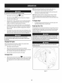
1
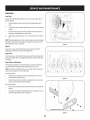
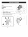
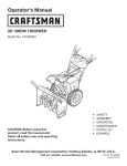
Operator's
Manual
CRRFr MRN
30" SNOW THROWER
Model No. 247.883961
,, SAFETY
o ASSEMBLY
OPERATION
MAINTENANCE
PARTS LIST
o ESPANOL
CAUTION" Before using this
product, read this manual and
follow all safety rules and operating
instructions.
Sears Brands
Management
Corporation,
Visit our website:
Hoffman
www.craftsman.com
Estates,
IL 60179, U.S.A.
FormI/o 769-08184C
(June21,2013)
WarrantyStatement
..............................
SafeOperationPractices......................
Assembly
....................................
Operation..................................
Service&Maintenance
......................
Page2
Pages3-6
Pages8-12
Pages13-17
Pages18-23
Off-Season
Storage
.............................
Page24
Troubleshooting
...............................
Page26
PartsList...................................
Pages28-44
RepairProtectionAgreement
....................
Page47
Espa_ol
........................................
Page48
CRAFTSMAN
TWOYEARFULLWARRANTY
FORTWOYEARS
fromthedateof purchase,
this productiswarrantedagainstanydefectsin materialor workmanship.
Defectiveproductwill receivefree
repairorfreereplacement
if repairisunavailable.
ADDITIONALLIFETIME
LIMITEDWARRANTY
on UPPERand LOWERCHUTE
FORASLONG
ASITISUSED
bytheoriginalownerafterthesecondyearfromthedateofpurchase,the
upperandlowerchuteofthissnowthrowerare
warrantedagainstanydefectsin materialor workmanship
asverifiedbya Sears
authorizedserviceprovider.With proofofpurchase,
youwill receivea new
chutefreeofcharge.Youareresponsible
for thelaborcostofinstallationandanycostincurredto verifythedefect.
Forwarrantycoverage
detailsto obtainrepairor replacement,
visitthewebsite:www.craftsman.com
ThiswarrantycoversONLY
defectsin materialandworkmanship.
Warrantycoverage
doesNOTinclude:
•
Expendable
itemsthatcanwearoutfrom normalusewithin thewarrantyperiod,includingbutnotlimitedto augers,augerpaddles,drift cutters,skid
shoes,shaveplate,shearpins,sparkplug,air cleaner,belts,andoilfilter.
•
Standard
maintenance
servicing,oil changes,
ortune-ups.
•
Tirereplacement
orrepaircausedbypunctures
from outsideobjects,suchasnails,thorns,stumps,orglass.
•
Tireor wheelreplacement
or repairresultingfrom normalwear,accident,or improperoperationormaintenance.
•
Repairsnecessary
becauseofoperatorabuse,includingbutnot limitedto damagecausedbyover-speeding
theengine,orfrom impactingobjectsthat
bendtheframe,augershaft,etc.
•
Repairsnecessary
becauseofoperatornegligence,
includingbutnot limitedto, electricalandmechanical
damagecausedbyimproperstorage,failureto
usethepropergradeandamountofengineoil,orfailureto maintaintheequipmentaccording
to theinstructions
containedinthe operator's
manual.
•
Engine(fuelsystem)cleaningorrepairscausedbyfueldeterminedto be contaminated
or oxidized(stale).Ingeneral,fuelshouldbe usedwithin 30days
ofitspurchasedate.
•
Normaldeteriorationandwearoftheexteriorfinishes,or productlabelreplacement.
Thiswarrantyisvoidif thisproductiseverusedwhileprovidingcommercial
services
or if rentedto anotherperson.
Thiswarrantygivesyouspecificlegalrights,andyoumayalsohaveotherrightswhichvaryfrom stateto state.
SearsBrandsManagement
Corporation,
NoffmanEstates,
IL60179
Engine Oil:
5W-30
Model Number
Fuel:
Unleaded Gasoline
Serial Number
Engine:
MTD
Date of Purchase
Record the model number, serial number,
and date of purchase above.
© Sears Brands, LLC
2
Thissymbolpointsout importantsafety instructionswhich, if not
followed, couldendangerthe personalsafetyand/or property of
yourself and others.Readandfollow all instructions in this manual
beforeattempting to operatethis machine.Failureto complywith these
instructions
may resultin personalinjury.Whenyou seethis symbol, HEED
ITSWARNING!
CALIFORNIA
PROPOSITION
65
EngineExhaust,someof its constituents,and certain vehiclecomponents
containor emit chemicalsknownto Stateof Californiato causecancerand
Thismachinewasbuilt to beoperatedaccordingto the safeoperation
practicesin this manual.Aswith anytype of powerequipment,
carelessnessor error on the part of the operatorcanresultin seriousinjury.
Thismachineiscapableof amputating fingers, hands,toesandfeet and
throwingdebris. Failureto observethefollowing safety instructions
could
resultin seriousinjuryor death.
Your Responsibility--Restrict the useof this powermachineto
personswho read,understandandfollow the warningsand instructionsin
this manualandon the machine.
SAVETHESEINSTRUCTIONS!
birth defectsor other reproductiveharm.
TRAINING
Disengage
all controlleversbeforestartingtheengine.
Read,understand,andfollowall instructionsonthe machineandinthe
manual(s)beforeattemptingto assembleandoperate.Failureto dosocan
resultinseriousinjury tothe operatorand/orbystanders.Keepthis manual
inasafeplaceforfutureandregularreferenceandfororderingreplacement
Adjustcollectorhousingheightto cleargravelor crushedrocksurfaces.
parts.
Letengineandmachineadjustto outdoortemperaturebeforestartingto
clearsnow.
Befamiliarwith all controlsandtheir properoperation.Knowhowto stop
the machineanddisengagethemquickly.
Neverallowchildrenunder14yearsof ageto operatethis machine.Children
14andovershouldreadandunderstandthe instructionsandsafeoperation
practicesinthis manualandonthe machineandbetrainedandsupervised
byanadult.
Neverallowadultsto operatethismachinewithout properinstruction.
Thrownobjectscancauseseriouspersonalinjury.Planyoursnow-throwing
patternto avoiddischargeof materialtowardroads,bystandersandthe like.
Keepbystanders,
petsandchildrenat least75feetfrom the machinewhileit
isin operation.Stopmachineif anyoneentersthe area.
Exercise
cautionto avoidslippingor falling, especiallywhenoperatingin
reverse.
PREPARATION
Thoroughlyinspect
the areawherethe equipmentisto beused.Removeall
doormats,newspapers,
sleds,boards,wiresandotherforeignobjects,which
couldbetrippedoveror thrownbythe auger/impeller.
Alwayswearsafetyglasses
or eyeshieldsduringoperationandwhile
performinganadjustmentor repairto protectyoureyes.Thrownobjects
whichricochetcancauseseriousinjuryto the eyes.
Donot operatewithout wearingadequatewinteroutergarments.Donot
wearjewelry,longscarvesorotherlooseclothing,whichcouldbecome
entangledin movingparts.Wearfootwearwhichwill improve
footing on
slipperysurfaces.
Usea groundedthree-wireextensioncordandreceptacleforall machines
with electricstartengines.
Neverattemptto makeanyadjustmentswhileengineisrunning,except
wherespecificallyrecommended
inthe operator'smanual.
Safe Handling
of Gasoline:
Toavoid personalinjuryor property damageuseextreme carein handling
gasoline.Gasolineisextremely flammable andthe vaporsareexplosive.
Seriouspersonalinjurycan occurwhengasolineis spilledon yourselfor your
clotheswhichcanignite. Washyour skinandchangeclothesimmediately.
Useonlyanapprovedgasolinecontainer.
Neverfill containersinsidea vehicleor ona truckor trailerbedwitha plastic
liner.Alwaysplacecontainersonthe groundawayfrom yourvehiclebefore
filling.
Whenpractical,removegas-poweredequipmentfrom the truckor
trailer andrefuelit onthe ground.Ifthisis not possible,thenrefuelsuch
equipmenton atrailerwith aportablecontainer,ratherthanfrom agasoline
dispensernozzle.
Keepthe nozzleincontactwith the rim ofthe fuel tankor containeropening
at all timesuntil fuelingiscomplete.Donot usea nozzlelock-opendevice.
Extinguishall cigarettes,cigars,pipesandothersourcesof ignition.
Neverfuel machineindoors.
Neverremovegascapor addfuel whilethe engineishot or running.Allow
engineto coolat leasttwo minutesbeforerefueling.
Neveroverfill fueltank.Filltankto nomorethan1/2inchbelowbottomof
filler neckto allowspacefor fuelexpansion.
Replace
gasolinecapandtightensecurely.
Ifgasolineisspilled,wipeit offthe engineandequipment.Moveunitto
anotherarea.Wait.5minutesbeforestartingtheengine.
To
reduce
firehazards,
keep
machine
free
ofgrass,
leaves,
orother
debris
build-up.
Clean
upoilorfuelspillage
and
remove
any
fuelsoaked
debris.
Never
store
themachine
orfuelcontainer
inside
where
there
isanopen
flame,
spark
orpilot
light
asonawater
heater,
space
heater,
furnace,
clothes
dryer
orother
gas
appliances.
OPERATION
Useonlyattachmentsandaccessories
approvedbythe manufacturer(e.g.
wheelweights,tire chains,cabsetc.).
Whenstartingengine,pull cordslowlyuntil resistanceisfelt, thenpull
rapidly.Rapidretractionofstartercord(kickback)will pullhandandarm
towardenginefasterthanyoucanletgo. Brokenbones,fractures,bruisesor
sprainscouldresult.
Ifsituationsoccurwhicharenot coveredinthismanual,usecareandgood
judgment.
Donot put handsor feetnearrotatingparts,inthe auger/impellerhousing
or chuteassembly.
Contactwith the rotatingpartscanamputatehandsand
feet.
CLEARING
Theauger/impellercontrolleverisasafetydevice.Neverbypassits
operation.Doingsomakesthe machineunsafeandmaycausepersonal
injury.
Handcontactwith the rotatingimpellerinsidethedischargechuteisthe most
commoncauseof injuryassociated
with snowthrowers.Neveruseyourhandto
cleanout the dischargechute.
Thecontrolleversmustoperateeasilyin bothdirectionsandautomatically
returnto the disengagedpositionwhenreleased.
Toclearthe chute:
A CLOGGED
DISCHARGE
CHUTE
a.
SHUTTHE
ENGINE
OFF!
Neveroperatewith amissingor damagedchuteassembly.Keepall safety
devicesin placeandworking.
b.
Wait 10secondsto besurethe impellerbladeshavestopped
rotating.
Neverrunanengineindoors
or inapoorlyventilatedarea.Engineexhaust
containscarbonmonoxide,anodorlessanddeadlygas.
c.
Alwaysuseaclean-outtool, not yourhands.
MAINTENANCE
& STORAGE
Donot operatemachinewhileunderthe influence
of alcoholor drugs.
Nevertamperwith safetydevices.Checktheirproperoperationregularly.
Referto the maintenanceandadjustmentsectionsof thismanual.
Mufflerandenginebecomehot andcancauseaburn.Donot touch.Keep
childrenaway.
Beforecleaning,repairing,or inspecting
machinedisengageall control
leversandstopthe engine.Waituntil the auger/impellercometo acomplete
stop.Disconnect
thesparkplugwire andgroundagainstthe engineto
preventunintendedstarting.
Exercise
extremecautionwhenoperatingonor crossinggravelsurfaces.Stay
alertforhiddenhazardsor traffic.
Exercise
cautionwhenchangingdirectionandwhileoperatingonslopes.Do
not operateon steepslopes.
Checkboltsandscrewsforpropertightnessat frequentintervals
to keepthe
machineinsafeworkingcondition.Also,visuallyinspect
machineforany
damage.
Planyoursnow-throwingpatternto avoiddischargetowardswindows,
walls,carsetc.Thus,avoidingpossiblepropertydamageor personalinjury
causedbyaricochet.
Donot changethe enginegovernorsettingor over-speed
the engine.The
governorcontrolsthe maximumsafeoperatingspeedof the engine.
Neverdirectdischargeat children,bystanders
andpetsor allowanyonein
front of the machine.
Snowthrowershaveplatesandskidshoesaresubjectto wearanddamage.
Foryoursafetyprotection,frequentlycheckall componentsandreplace
with originalequipmentmanufacturer's
(OEM)partsonlyaslistedinthe
Partspagesofthisoperator'smanual.Useof partswhichdonot meetthe
originalequipmentspecifications
mayleadto improper
performanceand
compromisesafety!
Donot overloadmachinecapacitybyattemptingto clearsnowat too fastof
arate.
Neveroperatethismachinewithoutgoodvisibilityor light. Alwaysbesureof
yourfootingandkeepafirm holdon the handles.Walk,neverrun.
Disengage
powerto the auger/impellerwhen transportingor not in use.
Checkcontrolleversperiodicallyto verifytheyengageanddisengage
properlyandadjust,if necessary.
Referto the adjustmentsectioninthis
operator'smanualfor instructions.
Neveroperatemachineat hightransportspeedsonslipperysurfaces.Look
downandbehindandusecarewhenbackingup.
If the machineshouldstartto vibrateabnormally,stopthe engine,
disconnectthe sparkplugwire andgroundit againstthe engine.Inspect
thoroughlyfordamage.Repairanydamagebeforestartingandoperating.
Maintainor replacesafetyandinstruction
labels,asnecessary.
Observe
properdisposallawsandregulationsforgas,oil,etc.to protectthe
environment.
Disengage
all controlleversandstopenginebeforeyouleavethe operating
position(behindthe handles).Waituntil the auger/impellercomesto
acompletestopbeforeuncloggingthe chuteassembly,
makingany
adjustments,or inspections.
Priorto storing,runmachineafewminutesto clearsnowfrom machineand
preventfreezeupof auger/impeller.
Neverstorethe machineor fuelcontainerinsidewherethereisanopen
flame,sparkor pilot light suchasa waterheater,furnace,clothesdryeretc.
Neverput yourhandin the dischargeor collectoropenings.Donot unclog
chuteassemblywhileengineis running.Shutoff engineandremainbehind
handlesuntil all movingpartshavestoppedbeforeunclogging.
Alwaysreferto the operator'smanualforproperinstructionsonoff-season
storage.
4
Checkfuelline,tank,cap,andfittings frequentlyfor cracksor leaks.Replace
if necessary.
Donot crankenginewith sparkplug removed.
Accordingto the ConsumerProductsSafetyCommission
(CPSC)
andthe
U.S.Environmental
ProtectionAgency(EPA),
thisproducthasan Average
Useful Life of seven(7)years,or 60 hoursofoperation.Atthe endof
the Average Useful Life havethe machineinspectedannuallybyan
authorizedservicedealerto ensurethat all mechanical
andsafetysystems
areworkingproperlyandnotwornexcessively.
Failureto dosocanresultin
accidents,
injuriesor death.
DO NOT MODIFY
ENGINE
Toavoidseriousinjuryor death,do notmodifyenginein anyway. Tampering
with the governorsetting canlead to arunawayengineandcauseit to
operateat unsafespeeds.Nevertamper with factory setting of engine
governor.
NOTICE
REGARDING
EMiSSiONS
Engineswhich are certifiedto complywith Californiaandfederal EPA
emissionregulations for SORE
(SmallOff RoadEquipment)arecertified
to operate on regularunleadedgasoline,and mayincludethe following
emissioncontrol systems:EngineModification (EM),OxidizingCatalyst(0C),
SecondaryAir injection(SAI)andThreeWayCatalyst(TWC)if soequipped.
SPARK ARRESTOR
e
This machineisequippedwith an internalcombustionengine andshould
not be usedon or near any unimprovedforest-covered,brushcoveredor
grass-coveredland unlessthe engine'sexhaust systemis equippedwith a
sparkarrestormeeting applicable localor state laws (if any).
Ira sparkarrestoris used,it shouldbe maintained in effective working order
bythe operator. In the State of Californiathe aboveisrequired bylaw (Section
4442of the CaliforniaPublicResourcesCode).Otherstates mayhavesimilar
laws.Federallaws apply on federal lands.
Asparkarrestorfor the muffler is availablethrough your nearestSearsParts
andRepairServiceCenter.
SAFETY
SYMBOLS
Thispage depicts and describes safety symbols that may appear on this product. Read, understand, and follow all instructions on the machine before
attempting
to assemble and operate.
READ THE OPERATOR'S MANUAL(S)
Read, understand,
and follow
all instructions
in the manual(s) before
attempting
to assemble
and
operate
WARNING--
ROTATING BLADES
Keep hands out of inlet and discharge openings
inside
WARNING--
blades
while
machine is running. There are rotating
blades
ROTATING AUGER
Do not put hands or feet near rotating
Contact with the rotating
WARNING--THROWN
This machine
parts, in the auger/impeller
parts can amputate
can cause serious personal
injury.
IS FLAMMABLE
before refueling.
CARBON MONOXIDE
Never run an engine indoors or in a poorly ventilated
monoxide, an odorless and deadly gas.
area. Engine exhaust contains carbon
ELECTRICAL SHOCK
Do not use the engine's
WARNING--
or chute assembly.
OBJECTS
Allow the engine to cool at least two minutes
WARNING--
housing
hands and feet.
may pick up and throw and objects which
WARNING--GASOLINE
WARNING--
machine is running. There are rotating
ROTATING BLADES
Keep hands out of inlet and discharge openings
inside
WARNING--
while
electric starter in the rain
HOT SURFACE
Engine parts, especially the muffler,
muffler to cool before touching.
WARNING:
Your Responsibility--Restrict
the warnings
and instructions
in this manual
become extremely
the use of this power machine
hot during
to persons
and on the machine.
SAVETHESEiNSTRUCTIONS!
6
operation.
Allow engine and
who read, understand
and follow
This page left intentionally blank.
7
f
NOTE:References
to rightor left sideofthe snowthroweraredeterminedfrom
behindthe unit in theoperatingposition(standingdirectlybehindthe snow
thrower,facingthe handlepanel).
Removing FromCarton
1.
Cutthe cornersof the cartonandlaythe sidesflat on theground.Remove
anddiscardall packinginserts.
2.
Movethe snowthrowerout of the carton.
3.
Makecertainthe cartonhasbeencompletelyemptiedbeforediscardingit.
Assembly
1.
Observe
the lowerrearareaof the snowthrowerto besurebothcablesare
alignedwith rollerguidesbeforepivotingthe handleupward.
2.
a.
Placetheshift [everinthe F6position.
b.
Puffup andbackonupperhandleasshownin Figure1.Asyouare
raisingthe handleupward,makesurethat bothendsof the center
cablearepositionedproperlyinthe brackets.SeeFigure2.Align
upperhandlewith the lowerhandle.
c.
Tightenhandknobssecuringupperhandleto lowerhandle.Remove
anddiscardanyrubberbands,if present.Theyarefor packaging
purposesonly.
Figure2
f
Removecotterpin, wingnut,andhexscrewfrom chutecontrolheadand
clevispinandbow-tiecotterpinfrom chutesupportbracket.SeeFigure3.
ChuteControl Head
Bracket
i,
Chute
-t
Figure3
J
Figure 1
8
3.
Insertthe roundendofthe chutecontrolrodinto inputofchutecontrol
head.Pushrodasfar intothe chutecontrolheadaspossible,keepingthe
holesinthe rodpointingupward.SeeFigure4.
4.
Placechuteontochutebaseandensurechutecontrolrodispositionedunder
handlepanel.Securechutecontrolheadto chutesupportbracketwithclevis
pinandbow-tiecotterpinremovedinstep 1.SeeFigure5.
5.
Finishsecuringchutecontrolheadbyinstallinghexbolt andwing nut.See
Figure6.
6.
Insertthe otherendof thechutecontrolrodinto the inputshaftbelowthe
handlepanel.Makesureto lineupthe flat endof the rodandthe flat end
ofthe inputshaft.Youmayneedto rotatethe rodarounduntil thesetwo
surfaceslineup.SeeFigure7.
f
Figure 6
f
,.
J
Figure4
Figure7
Figure5
9
F
Pushthe chutecontrolrodtowardthe controlpane[until the holeinthe rod
linesupwith the middleholeinthe chutecontrolinputandinsertthe cotter
pin. SeeFigure&
s
//
NOTE:
Thereisareferenceholeprovidedat rearendof controlrodto help
knowwhenholesarevertical
i
!
NOTE:
Theholefurthestfrom the chutecontrolheadisusedto achieve
furtherengagementofthe chutecontrolrodintothe inputshaftif required.
Referto the Maintenance
& AdjustmentssectionforChuteControlRod
adjustment.
Theholeclosestto the chutecontrolheadisusedfor manualmovementof
the chuteassemblyif required.Refertothe Controls& Features
section.
8.
Checkthat the cablesareproperlyroutedthroughthe cableguideontop of
the engine.SeeFigure9.
NOTE:Forsmoothestoperation,the cablesshouldall beto the left ofthe
chutecontrolrod.
Set-Up
ShearPins
Holes
arelocated
intheplastic
dashpanelforconvenient
shearpinstorage.
See
Figure
10.RefertotheOperation
section
formoreinformation
regarding
shear
pin
replacement.
Figure9
s_ .......
=/
/
/
J
Figure
10
Figure8
10
ChuteClean-OutTool
f
Achuteclean-outtool isfastenedto the top ofthe augerhousingwith amounting
clip.SeeFigure11.Thetool isdesignedto cleara chuteassemblyof iceandsnow.
Thisitem isfastenedwith acabletieat the factory.Cutthe cabletie before
operatingthe snowthrower.
Neveruseyour handsto clearacloggedchute assembly.Shutoff engine
and remainbehind handlesuntil all moving parts havestoppedbefore
using the clean-outtool to clearthe chute assembly.
Drift Cutters
Removethe two screwsandwingknobsthatsecureeachdrift cutter,and
removethemfromthe sidesof the augerhousing.
Turnthe drift cuttersaroundandpositionthemasshownin Figure12to the
outsideof the augerhousing.
2.
//
/
Attachthe drift cutterswith the screwsandwingknobsremovedearlier.See
Figure13.
3.
J
Tire Pressure
Figure12
f
Underany circumstancedo not exceedmanufacturer'srecommendedpsi.
Equaltire pressureshouldbe maintained at all times. Excessivepressure
when seatingbeadsmaycausetirelrim assemblyto burstwith force
sufficient to causeseriousinjury. Referto sidewallof tire for recommended
pressure.
Thetiresareover-inflatedforshippingpurposes.Checkthe tire pressurebefore
operatingthe snowthrower.Referto the tire sidewall fortire manufacturer's
recommended
psianddeflate(orinflate)the tiresasnecessary.
NOTL::
Equaltire pressureisto bemaintainedat all timesforperformancepurposes.
f
ChuteClean-outTool
Figure13
Figure11
11
Adjustments
f
Skid Shoes
Thesnowthrowerskidshoesareadjustedupwardat the factoryfor shipping
purposes.
Adjustthemdownward,if desired,priorto operatingthe snowthrower.
Smooth Surface
it isnotrecommended
that youoperate this snowthrower on gravelas
it caneasilypickup andthrowloose gravel,causingpersonalinjuryor
damageto thesnowthrowerandsurroundingproperty.
Forclosesnowremovalon asmoothsurface,raiseskidshoeshigheronthe
augerhousing.Referto Figure14.
Useamiddleor lowerpositionwhenthe areato beclearedisuneven,suchas
agraveldriveway.
flOTE:Ifyouchooseto operatethe snowthroweron agravelsurface,keep
the skidshoesinpositionformaximumclearancebetweenthe groundand
the shaveplate.
UnevenSurface
Toadjustthe skidshoes:
1.
Loosenthe four hexnuts (two oneachside)andcarriagebolts.Moveskid
shoesto desiredposition.SeeFigure14.
2.
Makecertainthe entirebottomsurfaceof skidshoeisagainstthe groundto
avoidunevenwearon the skidshoes.
3.
Retightennutsandboltssecurely.
Figure14
f
Auger Control
Priorto operating yoursnowthrower, carefully read andfollow all
instructions
below. Performall adjustmentsto verify your snowthrower is
operating safelyand properly.
\
Checkthe adjustmentof theaugercontrolasfollows:
1.
Theaugercontrolislocatedon the left handle.SeeFigure15inset.When
the augercontrolisreleasedandinthe disengaged"up" position,the cable
shouldhaveverylittle slack.ItshouldNOTbetight.
2.
Ina well-ventilatedarea,start thesnowthrowerengine.Referto Starting
the Engineinthe Operationsection.
3.
Whilestandinginthe operator'sposition(behindthe snowthrower),engage
the auger.
4.
Allowthe augerto remainengagedfor approximatelyten (10)seconds
beforereleasingthe augercontrol.Repeatthisseveraltimes.
\
Figure15
5.
Withthe augercontrolin the disengaged
"up" position,walk to thefront of
the machine.
7.
Toreadjust
thecontrolcable,loosen
theupperhexboltontheaugercable
bracket.
SeeFigure
15.
6.
Confirmthat the augerhascompletelystoppedrotatingandshowsNOsigns
of motion.Ifthe augershowsANYsignsof rotating,immediatelyreturnto
the operator'spositionandshutoffthe engine.WaitforALLmovingpartsto
stopbeforeadjustingthe augercontrol.
8.
Position
thebracket
upward
toprovide
moreslack(ordownward
to increase
cabletension).
9.
Retightenthe upperhexbolt.
10.
Repeatsteps2-6aboveto verify properadjustmenthasbeenachieved.
12
Shift Lever
Drive Control
J
Electric Chute Control
Headlight
(Joystick)
Auger Control
Manual
ChuteControl
Gas Cap _
.\
Chute Assembly
\
Wheel Steering Control
Drift Cutter
Muffler
\
Clean Out
Tool
Recoil Starter
Oil Fill
Handle
\
Auger
Housing
\
/
Augers
Skid Shoe
Oil Drain
J
Figure16
Nowthat youhavesetupyoursnowthrower,it's importantto becomeacquainted
with its controlsandfeatures.Referto Figure16.
Shift Lever
6
Theshiftleverislocatedonthe right sideofthe handlepanel.Placethe shift
leverintoanyof eightpositionsto controlthe directionoftravelandground
speed.
5
3
Forward
Yoursnowthrowerhassixforward(F)speeds.
Position
one(1)istheslowest
andpositionsix(6)isthefastest.
Reverse
4
t 2
F1
Key
Thekeyisasafetydevice.It mustbefully inserted
in
orderfor the engineto start. Removethe keywhenthe
snowthrowerisnot in use.
NOTE:Donot turn the ignitionkeyinanattempt tostart
the engine.Doingsomaycauseit to break.
ChokeControl
Thechokecontrolisfoundonthe rearof theengineandis
activatedbyturningthe rotarychokeknobto the CHOKE
position.Activatingthe chokecontrolclosesthe choke
plateonthe carburetorandaidsinstartingthe engine.
R1
Yoursnowthrowerhastworeverse
(R)speeds.
One(1)istheslowerandtwo(2)
isthefaster.
[I 2
ChuteAssembly
Drift Cutters
Snowdrawnintothe augerhousingisdischargedout the chuteassembly.
Thedrift cuttersaredesignedfor useindeepsnow.Theiruseisoptionalfor normal
snowconditions.Maneuverthe snowthrowersothatthe cutterspenetratea high
standingsnowdrift to assistsnowfalling into the augersforthrowing.
Meets ANSiSafetyStandards
CraftsmanSnowThrowersconformtothe safetystandardof the AmericanNationalStandardsInstitute(ANSI).
13
Throttlecontrol
DriveControl/Auger ControlLock
f
DRIVE
CONTROL
Thethrottle control islocated on the rear ofthe engine. Itregulates the speedof the
engineand willshut offthe enginewhen moved into the STOPposition.
Depressing
the primerforcesfueldirectlyintothe
engine'scarburetorto aidin cold-weatherstarting.
_J'
444
3X
Recoil Starter Handle
Thishandleisusedto manuallystartthe engine.
Thedrivecontrolislocatedon the right handle.Squeeze
the controlgripagainstthe
handleto engagethe wheeldrive.Release
to stop.
Electric Starter Button
Pressing
the electricstarterbuttonengagesthe engine'selectricstarterwhen
pluggedinto a 120Vpowersource.
Electric Starter Outlet
Requires
the useof athree-prongoutdoorextensioncordanda 120Vpowersource/
walloutlet.
OUFill
Thedrivecontrolalsolocksthe augercontrolsoyoucanoperatethe chute
directionalcontrolwithoutinterruptingthe snowthrowingprocess.Ifthe auger
controlisengagedsimultaneously
with the drivecontrol,the operatorcanrelease
the augercontrol(onthe left handle)andtheaugerswill remainengaged.Release
both controlsto stoptheaugersandwheeldrive.
NOTE:Alwaysreleasethe drivecontrolbeforechangingspeeds.Failureto dosowill
resultinincreasedwearon yourmachine'sdrivesystem.
ElectricChute Control
Engineoil levelcanbe checkedandoil addedthroughthe oil fill.
ELECTRIC
DIRECTIONAL
Headlight
Theheadlightison wheneverthe engineisrunning.
CHUTE
CONTROL
CHUTE TILT DOll
Auger
CHUTE
ROTATE
LEFT
Whenengaged,the augerbladesrotateanddrawsnowintothe augerhousing.
WheelSteeringControls
CHUTE
ROTATE
RIGHT
Theleft andfight wheelsteeringcontrolsarelocatedonthe undersideofthe
handles.Squeeze
the fight controlto turn right; squeeze
the left controlto turn left.
flOTE:Operatethe snowthrowerinopenareasuntil youarefamiliarwith these
controls.
AugerControl
/
Theelectricchutecontrol(Joystick)islocatedon the rightsideof the handlepanel.
AUGER
CONTROL
Tochangethe directionin whichsnowis thrown,movethe joystickto the
rightor to the left.
Tochangethe angle/distance
whichsnowisthrown,pivot thejoystick
forwardto tilt the chutedownandbackwardto tilt the chuteup.
Skid Shoes
Positionthe skidshoesbasedonsurfaceconditions.Adjustupwardforhard-packed
snow.Adjustdownwardwhenoperatingon gravelor crushedrocksurfaces.
Theaugercontrolislocatedon the left handle.Squeeze
the controlgripagainstthe
handleto engagethe augerandstartsnowthrowingaction.Release
to stop.
14
Manual ChuteControl
Clean-OutTool
Proceedasfollowsto utilizethe manualchutecontrol:
Removethe cotterpin fromeitherof the holesfurthestfromthe chute
assemblyon the chutecontrolhead.
2.
Neveruseyour handsto cleara cloggedchuteassembly.Shutoff engine
andremainbehindhandlesuntil all moving parts havestoppedbefore
using the clean-outtool to clearthe chuteassembly.
Pushinthe chutecontrolroduntil the holein it linesupwith the third hole
inthe chutecontrolhead.SeeFigure17.
Thechuteclean-outtool isconvenientlyfastenedto the rearof the augerhousing
with a mountingclip.Shouldsnowandicebecomelodgedinthe chuteassembly
duringoperation,proceedasfollowsto safelycleanthe chuteassemblyandchute
opening:
/
,/
1.
Release
boththeAugerControlandthe DriveControl.
2.
Stopthe enginebyremovingthe ignitionkey.
3.
Removethe clean-outtool fromthe clip whichsecuresit to the rearof the
augerhousing.
4.
Usethe shovel-shaped
endof theclean-outtool to dislodgeandscoopany
snowandicewhichhasformedinandnearthe chuteassembly.
5.
Refasten
the clean-outtool to the mountingclip onthe rearof the auger
housing,reinsertthe ignitionkeyandstart thesnowthrower'sengine.
6.
Whilestandinginthe operator'sposition(behindthe snowthrower),engage
the augercontrolforafew secondsto clearanyremainingsnowandicefrom
the chuteassembly.
//
/
Before Starting Engine
Figure17
3.
ReJnsert
the cotterpinthroughthisholeandthe chutecontrolrodasshown
in Figure17.
4.
Graspthe indentedportionof the chutecontrolrodandmanuallyrotatethe
chuteto the rightor to the left. SeeFigure18.
Read,understand,andfollow all instructionsandwarnings on the
machineand inthis manualbeforeoperating.
Oil
Theunit wasshippedwith oil in the engine.Checkoil levelbeforeeachoperationto
ensureadequateoil inthe engine.
NOTE:Besureto checkthe engineona levelsurfacewith theenginestopped.
1.
Removethe oil filler cap/dipstickandwipethe dipstickclean.
2.
Insertthe cap/dipstickintothe oil filler neck,but doNOTscrewit in.
3.
Removethe oil filler cap/dipstick.If the levelislow,slowlyaddoil (5W-30,
with a minimumclassificationof SF/SG)
until oil levelregistersbetweenhigh
(H)andlow (L).
J
/
/
/ /
,I
i
y
i
/
NOTE:Donot overfill.Overfillingwithoil mayresultinenginesmoking,hard
startingorsparkplugfouling.
/
4.
Figure 18
15
Replace
andtighten cap/dipstickfirmly beforestartingengine.
Gasoline
Electrk Starter
Useautomotivegasoline(unleadedor low leadedto minimizecombustionchamber
deposits)witha minimumof87 octane.Gasoline
with up to 10%ethanolor 15%
MTBE(MethylTertiaryButylEther)canbeused.Neveruseanoil/gasolinemixture
or dirty gasoline.Avoidgetting dirt, dust,or waterinthe fuel tank.DONOTuseE85
gasoline.
Refuelin awell-ventilatedareawith the enginestopped.Donot smokeor
allowflamesor sparksin the areawherethe engineisrefueledor where
gasolineisstored.
Donot overfillthe fuel tank.After refueling,makesurethe tank capisclosed
properlyandsecurely.
Becarefulnot to spillfuel whenrefueling.Spilledfuel or fuelvapormay
ignite.Ifanyfuel isspilled,makesuretheareaisdry beforestartingthe
engine.
Theelectric starter isequippedwith a groundedthree-wire power plug,
andisdesignedto operate on 120voltAChouseholdcurrent.It must be
usedwith a properly groundedthree-prong receptacleat all times to avoid
the possibilityof electrk shock.Follow all instructionscarefully prior to
operatingthe electricstarter. DONOTuseelectric starter in the rain.
Determinethatyourhome'swiring isathree-wiregroundedsystem.Aska licensed
electricianif youarenot certain.
Ifyouhavea groundedthree-prongreceptacle,proceedasfollows.If youdonot
havethe properhousewiring, DONOTusethe electricstarterunderanyconditions.
1.
Avoidrepeatedor prolongedcontactwith skinor breathingof vapor.
Theextensioncordcan beany length, but must be ratedfor 15ampsat
125volts,groundedand ratedfor outdoor use.
Useextreme carewhen handlinggasoline.Gasolineisextremely
flammable and the vapors areexplosive.Neverfuel the machineindoorsor
while the engine ishotor running. Extinguishcigarettes,cigars,pipesand
other sourcesof ignition.
I.
Cleanaroundfuel fill beforeremovingcapto fuel.
2.
Afuel levelindicatorislocatedinthe fueltank.SeeFigure16inset.Be
carefulnot to overfill.Filltank untilfuel reachesthe fuel levelindicatorto
Pluganextensioncordinto the outletlocatedon the engine'ssurface.Plug
the otherendofextensioncordintoathree-prong120-volt,grounded,AC
outlet inawell-ventilatedarea.
2.
Movethrottlecontrolto FAST
(rabbit)_
11 position.
3.
Movechoketo the CHOKE
1,'_'1 position(coldenginestart).Ifengineis
warm,placechokeinRUNposition.
4.
Pushprimerthree(3)times,makingsureto coverventholein primerbulb
whenpushing.If engineiswarm,pushprimeronlyonce.Alwayscovervent
holewhen pushing.Coolweathermayrequireprimingto berepeated.
5.
Pushstarterbuttonto startengine.Oncethe enginestarts,immediately
releasestarterbutton. Electricstarterisequippedwith thermaloverload
protection;systemwill temporarilyshut-downto allowstarterto coolif
electricstarterbecomesoverloaded.
6.
Asthe enginewarms,slowlyrotatethe chokecontrolto RUNposition.If the
enginefalters,restartengineandrunwith chokeat half-chokepositionfora
shortperiodoftime,andthenslowlyrotatethe chokeinto RUNposition.
7.
Afterengineisrunning,disconnectpowercordfrom electricstarter.When
disconnecting,
alwaysunplugthe endat the walloutlet beforeunplugging
the oppositeendfromthe engine.
allowspaceforfuel expansion.
Starting TheEngine
Alwayskeephandsandfeet clearof moving parts. Donot usea pressurized
starting fluid. Vaporsareflammable.
flOTEtAllow the engineto warmup forafew minutesafterstarting.Theenginewill
not developfull poweruntil it reachesoperatingtemperatures.
1.
Makecertainboththe augercontrolanddrivecontrolareinthe disengaged
(released)
position.
2.
Insertkeyintoslot.Makesureit snapsinto place.Donot attemptto turn the
key.
NOTE:
Theenginecannotstartwithout the keyfullyinsertedinto the
ignitionswitch.
16
Recoil
Starter
NOTE:Whenselectinga DriveSpeed,usetheslowerspeedsuntilyouare
comfortableandfamiliarwith theoperationof the snowthrower.
2.
Donot pullthe starter handlewhile the enginerunning.
1.
Movethrottle controlto FAST
(rabbit)_J_ position.
2.
Movechoketo the CHOKE
I,'#1 position(coldenginestart).If engineis
flOTE:NEVER
repositiontheshift lever(changespeedsor directionof travel)
without first releasingthe drivecontrolandbringingthesnowthrowerto a
completestop.Doingsowill resultin prematurewearto the snowthrower'sdrive
system.
warm,placechokein RUNposition.
3.
4.
5.
Squeezethe drivecontrolagainstthe handleandthe snowthrowerwill
move.Release
it anddrivemotionwill stop.
ToEngageAuger
Pushprimerthree(3)times,makingsureto covervent holewhenpushing.
If engineiswarm,pushprimeronlyonce.Alwayscoverventholewhen
pushing.Coolweathermayrequireprimingto be repeated.
Toengagetheaugerandstartthrowingsnow,squeezethe augercontrol
againstthe left handle.Release
to stopthe auger.
Pullgentlyonthe starterhandleuntil it beginsto resist,then pullquickly
andforcefullyto overcome
the compression.
Donot releasethe handleand
allowit to snapback.ReturnropeSLOWLY
to originalposition.If required,
repeatthisstep.
ReplacingShearPins
Eachaugerbladeissecuredto the spiralshaftwith ashearpinandbow-tieclip.If
anaugerbladestrikesa foreignobjector icejam, the pinwill shearoff to prevent
damageto the blade.Ifan augerbladedoesnot turn, checkto seeif itspinhas
shearedoff. SeeFigure19.
Asthe enginewarms,slowlyrotatethe chokecontrolto RUNposition.Ifthe
enginefalters,restartengineandrunwith chokeat half-chokepositionfor a
shortperiodof time,andthenslowlyrotatethe chokeintoRUNposition.
NEVER
replacethe augershear pinswith anything otherthan SearsSKU#
88389/0EMPart No.738-04124Areplacementshearpins.Any damageto
the augergearboxor other components
asa result of failing to do sowill
NOTbe coveredbyyour snowthrower's warranty.
Toavoid unsupervisedengineoperation, never leavethe machine
unattended with the engine running. Turnthe engine off after useand
removekey.
Stopping TheEngine
Afteryouhavefinishedsnow-throwing,runenginefor afewminutesbefore
stoppingto helpdry offany moistureon the engine.
1.
Movethrottle controlto OFFposition.
2.
Removethe key.Removing
the keywill reducethe possibilityof
unauthorizedstartingof the enginewhileequipmentisnot inuse.Keepthe
keyina safeplace.Theenginecannotstartwithout the key.
3.
Wipeanymoistureawayfrom the controlson the engine.
Alwaysturn off the snowthrower's engine and removethe keypriorto
replacingshearpins.
ToEngageDrive
1.
With thethrottle controlinthe Fast(rabbit)_ _111position,moveshift lever
into oneof thesixforward(F)positionsor two reverse(R)positions.Selecta
speedappropriateforthe snowconditionsandapaceyou'recomfortable
with.
Figure19
17
MAINTENANCE
SCHEDULE
Followthe maintenance
schedulegivenbelow.Thischartdescribes
service
guidelinesonly.Usethe ServiceLogcolumnto keeptrackofcompleted
maintenancetasks.Tolocatethe nearestSearsServiceCenteror to scheduleservice,
Beforeperforming any type of maintenance/service,disengageall controls
andstop the engine.Wait until all moving parts havecometo a complete
stop. Disconnectsparkplug wire and ground it againstthe engine to
preventunintendedstarting.
simplycontactSearsat 1-800-4-MY-HOME
®.
I.
Engineoil level
1.
Check
2.
Looseor missinghardware
2.
Tightenor replace
3.
Unitandengine.
3.
Clean
Ist 5hours
I.
EngineoJl
1.
Change
Annuallyor 25hours
I.
Sparkplug
1.
Check
2.
Controllinkagesandpivots
2.
Lubewith light oil
3.
Wheels
3.
Lubewith multipurposeautogrease
4.
GearshaftandAugershaft
4.
Lubewith light oil
Annuallyor 50hours
I.
EngineoJl
1.
Change
Annuallyor 100hours
I.
Sparkplug
1.
Change
BeforeStorage
I.
Fuelsystem
1.
Runengineuntil it stopsfrom lackof=fuel
EachUseandevery5hours
GENERAL
RECOMMENDATIONS
CheckingEngine Oil
Beforelubricating, repairing,or inspecting,disengageall controlsandstop
engine.Wait until all movingparts havecometo acompletestop.
NOTE:Checkthe oil levelbeforeeachuseto besurecorrectoil levelismaintained.
Whenaddingoil to the engine,referto viscositychartbelow.Engineoil capacity
is1100ml(approx.37oz.).Donot over-fill.Usea4-stroke,or anequivalenthigh
detergent,premiumquality motoroil certifiedto meetor exceedU.S.automobile
manufacturer'srequirementsforserviceclassificationSG,SF.Motoroilsclassified
SG,SFwill showthisdesignationon thecontainer.
1.
Removethe oil filler cap/dipstkkandwipethe dipstickclean.
2.
Insertthe cap/dipstkkinto the oil filler neck,but do NOTscrewit in.
3.
Removethe oil filler cap/dipstick.Iflevelis low,slowlyaddoil until oil level
registersbetweenhigh(H)andlow (L).SeeFigure20.
4.
J
Figure20
Replace
andtighten cap/dipstickfirmly beforestartingengine.
Tip unitto drainoil intothe container.Usedoil mustbedisposedof at a
propercollectioncenter.
Changing EngineOil
NOTE:Change
the engineoil after the first 5 hoursof operationandoncea season
or every50 hoursthereafter.
1.
Drainfuel fromtank byrunningengineuntil the fueltank isempty.Besure
fuelfill capissecure.
2.
Placesuitableoil collectioncontainerunderoil drainplug.
3.
Removeoil drainplug.SeeFigure21on next page.
Usedoii isa hazardouswaste product. Disposeof usedoil properly. Donot
discardwith householdwaste. Checkwithyour localauthorities or Sears
ServiceCenterfor safedisposal/recyclingfacilities.
5.
18
Reinstallthe drainplugandtighten it securely.
Refillwith the recommended
oil andcheckthe oil level.SeeRecommended
OilUsagechart.Theengine'soil capacityis37ounces.
(oF)-40o-20 o 0o 200 400
(oc)
Oil Drain
-30° -20° -10 ° 0°
Plug
\
DONOTuse nondetergentoil or 2-strokeengine oil. It couldshorten the
engine'sservicelife.
7.
Reinstallthe oil filler cap/dipsticksecurely.
Figure21
Thoroughly
washyourhandswith soapandwater assoonaspossibleafter
handling usedoil.
SparkPlug
CheckingSparkPlug
DONOTcheckfor sparkwith sparkplug removed.DONOTcrankenginewith
sparkplug removed.
Ifthe engine hasbeenrunning,the muffler will bevery hot. Becarefulnot
to touchthe muffler.
NOTE:Checkthe sparkplugonceaseasonor every25 hoursof operation.Change
the sparkplugonceaseasonor every100hours.Toensureproperengineoperation,
the sparkplug mustbeproperlygappedandfreeof deposits.
1.
Removethe sparkplugbootandusea sparkplugwrenchto removethe
plug.SeeFigure22.
2.
Visuallyinspectthe sparkplug.Discardthe sparkplugif thereisapparent
wear,or if the insulatoriscrackedor chipped.Cleanthe sparkplugwith a
wirebrushif it isto be reused.
3.
Measurethe pluggapwith afeelergauge.Correctasnecessary
bybending
sideelectrode.SeeFigure23.Thegapshouldbesetto .02-.03inches(0.600.80mm).
4.
Checkthatthe sparkplug washerisin goodconditionandthreadthe spark
plug inbyhandto preventcross-threading.
5.
Afterthe sparkplug isseated,tightenwith asparkplugwrenchto compress
the washer.
SparkPlugBoot
Figure22
Electrode
NOTE:Wheninstallinganewsparkplug,tighten 1/2-turnafterthe sparkplug
seatsto compressthe washer.Whenreinstallinga usedsparkplug,tighten 1/8- to
1/4-turnafter the sparkplugseatsto compressthewasher.
Thesparkplug mustbe tightened securely.Aloosesparkplug can become
very hot andcan damagethe engine.
Figure23
19
Lubrication
"I
GearShaft
Thegear(hex)shaftshouldbelubricatedat leastonceaseasonor after every25
hoursof operation.
I.
Topreventspillage,removeall fuel fromtank byrunningengineuntil it
stops.
2.
Carefullypivotthe snowthrowerupandforwardsothat it restsonthe auger
housing.
3.
Removethe lowerframecoverfrom the undersideof the snowthrowerby
removingthe self-tappingscrewswhichsecureit.
4.
Applya lightcoatingof engineoil (or3-in-1oil) to the hexshaft.SeeFigure
24.
NOTE:
Whenlubricatingthe hexshaft,becarefulnot to get anyoil onthe aluminum
driveplateor rubberfrictionwheel.Doingsowill hinderthe snowthrower'sdrive
system.Wipeoffany excessor spilledoil.
Wheels
J
Figure24
f
Atleastonceaseason,removebothwheels.Cleanandcoattheaxleswitha
multipurposeautomotivegreasebeforereinstallingwheels.
Auger Shaft
Atleastonceaseason,removethe shearpinson augershaft.Spraylubricantinside
shaft,andaroundthe spacers
andflangebearingsfoundat eitherendof the shaft.
SeeFigure25.
ShavePlate and Skid Shoes
Theshaveplateandskidshoeson the bottomofthe snowthroweraresubjectto
wear.Theyshouldbecheckedperiodkallyandreplacedwhennecessary.
NOTE:
Theskidshoeson thismachinehavetwo wearedges.Whenonesidewears
out,theycanberotated180°to usethe otheredge.
Toremoveskidshoes:
Remove
thetwocarriage
bolts,washers,
andhexflangenutsthatsecure
eachskidshoetothesnowthrower.
2.
Reassemble
newskidshoeswith the fourcarriagebolts(two on eachside),
washers,andhexflangenuts.Referto Figure26.
f
Toremoveshaveplate:
1.
Removethe carriageboltsandhexnutswhichattachit to the snowthrower
housing.
2.
Reassemble
newshaveplate,makingsureheadsof carriageboltsareto the
insideof housing.Tightensecurely.SeeFigure26.
NOTE:Augersnot shown for clarity.
Figure26
20
f
Adjustments
Shift Cable
If the full rangeof speeds(forwardandreverse)cannotbeachieved,referto the
figureto the fight andadjusttheshift cableasfollows:
I.
Placethe shift leverinthe fastestforwardspeedposition(F6).
2.
Loosenthe hex nut onthe shift cableindexbracket.SeeFigure27.
3.
Pivotthe bracketdownwardtotake upslackinthe cable.
4.
Retightenthe hexnut.
Drive Control
Whenthe drivecontrolis releasedandinthe disengaged
"up" position,the cable
shouldhaveverylittle slack.ItshouldNOTbetight. Also,if thereisexcessive
slack
inthe drivecableor if the unit experiences
intermittentdrivewhileusing,the cable
mayneedto beadjusted.Checkthe adjustmentof the drivecontrolasfollows:
I.
With thedrivecontrolreleased,pushthe snowthrowergentlyforward.The
unit shouldroll freely.
2.
Engagethe drivecontrolandgentlyattemptto pushthe snowthrower
forward.Thewheelsshouldnot turn. Theunit shouldnot roll freely.
3.
With thedrivecontrolreleased,movethe shift leverbackandforth between
Figure27
the R2positionandthe F6positionseveraltimes.Thereshouldbeno
resistanceinthe shift lever.
4.
If anyof the abovetestsfailed,the drivecableisinneedof adjustment.
Proceedasfollows:
a.
Shutoff the engineasinstructedinthe Operationsection.
b.
Loosenthe lowerhexbolt onthe drivecablebracket.SeeFigure28.
c.
Positionthe bracketupwardto providemoreslack(ordownwardto
increasecabletension).
d.
Retightenthe lowerhexbolt.
ChuteControlRod
Toachievemorechutecontrolrodengagementinthe inputshaftunderthe handle
panel,the chutecontrolrodwill haveto beadjusted.Referto Figure29.
Figure28
Toadjustthisrod,proceedasfollows:
I.
Removethe cotterpin fromthe holeclosestto the chutecontrolheadon the
chutecontrolinput.
2.
Pullout the chutecontrolroduntilthe holeinit linesupwith the otherhole
inthe chutecontrolinput.
3.
Reinsertthe cotterpinthroughthisholeandthe chutecontrolrod.
Figure29
21
f
Auger
Control
Referto theAssemblysectionforinstructionson adjustingtheaugercontrolcable.
Skid Shoes
Referto theAssemblysectionforinstructionson adjustingtheskidshoes.
Belt Replacement
Auger Belt
Toremoveandreplaceyoursnowthrower'saugerbelt, proceedasfollows:
I.
Topreventspillage,removeall fuel fromtank byrunningengineuntil it
stops.
2.
Removethe plasticbelt coveronthe front of the enginebyremovingthetwo
self-tappingscrews.SeeFigure30.
3.
Rollthe augerbeltoffthe enginepulley.SeeFigure31.
4.
Carefullypivotthe snowthrowerupandforwardsothat it restsonthe auger
housing.
5.
Removethe framecoverfrom the undersideof the snowthrowerby
removingfourself-tappingscrewswhichsecureit. SeeFigure32.
J
Figure 30
f
........................................
/
................
; /
Figure31
Figure 32
22
Loosenandremovethe shoulderscrewwhichactsasabelt keeper.Referto
Figure33.
Removethe belt fromaroundthe augerpulley,andslipthe belt betweenthe
supportbracketandtheaugerpulley.SeeFigure34.
NOTE:Engagingthe augercontrolwill easeremovalandreinstallationof the
belt.
8.
Reassemble
augerbeltbyfollowing instructionsinreverseorder.
flOTE:DoNOTforgetto reinstallthe shoulderscrewandreconnectthespring
to the frameafterinstallingareplacement
augerbelt.
Performthe AugerControltestoutlinedinthe Assemblysectionof this
manual.
Drive Belt
flOTE:Severalcomponentsmustberemovedandspecialtoolsarerequiredin order
to replacethe snowthrower'sdrivebelt. Contactthe nearestSearsParts& Repair
Centerto havethe drivebelt replaced.
FrictionWheel inspection
Figure33
If the snowthrowerfailsto drivewith the drivecontrolengaged,andperforming
the DriveControlCableAdjustmentfailsto correctthe problem,the frictionwheel
mayneedto bereplaced.Examinethe frictionwheelrubberforsignsof wearor
crackingandreplacewheelif necessary.
flOTE:Severalcomponentsmustberemovedandspecialtoolsarerequiredin order
to replacethissnowthrower'sfrictionwheel.Ifyourfrictionwheelneedsto be
replaced,contactthe nearestSearsParts& RepairCenter.
Toinspectthe frictionwheel,proceedasfollows:
1.
Allowthe engineto rununtil it isout of fuel. Donot attemptto pourfuel
fromthe engine.
2.
Carefullypivotthe snowthrowerupandforwardsothat it restson theauger
housing.
3.
Removethe framecoverfrom the undersideof the snowthrowerby
removingfourself-tappingscrewswhichsecureit. Referto Figure32.
4.
Examinethe frictionwheelforsignsof wearor cracking.
i
:_
Figure34
23
•
/
If the snowthrowerwill not beusedfor 30daysor longer,or if it is theendof thesnowseasonwhenthe lastpossibilityof snowisgone,the equipmentneedsto bestored
properly.Followstorageinstructionsbelowto ensuretop performancefrom thesnowthrowerformanymoreyears.
PreparingEngine
PreparingSnowThrower
Enginesstoredover30daysneedto bedrainedof fuel to preventdeteriorationand
gumfromforminginfuel systemor on essentialcarburetorparts.If thegasolinein
yourenginedeterioratesduringstorage,youmayneedto havethe carburetor,and
otherfuel systemcomponents,servicedor replaced.
Whenstoringthe snowthrowerin anunventilatedor metalstorageshed,
careshouldbetakento rustproofthe equipment.Usinga lightoil or silicone,
coatthe equipment,especially
anychains,springs,bearingsandcables.
1.
Removeall fuel fromtank byrunningengineuntil it stops.Donot attemptto
pourfuelfrom the engine.
Followlubricationrecommendations.
2.
Changetheengineoil.
3.
Removesparkplugandpourapproximately1oz.(30ml) ofcleanengineoil
into the cylinder.Pullthe recoilstarterseveraltimesto distributetheoil, and
reinstallthe sparkplug.
4.
Cleandebrisfrom aroundengine,andunder,around,andbehindmuffler.
Applya lightfilm ofoil on anyareasthat aresusceptibleto rust.
Removeall dirt fromexteriorof engineandequipment.
Storeequipmentinaclean,dry area.
Inflatethe tiresto the maximumPSI.Referto tire sidewall.
Storeinaclean,dry andwell ventilatedareaawayfromanyappliancethat
operateswith aflameor pilot light,suchasa furnace,waterheater,or
clothesdryer.Avoidanyareawitha sparkproducingelectricmotor,or where
powertoolsareoperated.
Neverstore snowthrower with fuel in tank indoorsor in poorlyventilated
areas,where fuel fumes may reachan openflame, sparkor pilotlight ason
a furnace,water heater,clothesdryeror gasappliance.
If possible,avoidstorageareaswith high humidity.
Keepthe enginelevelinstorage.Tiltingcancausefuelor oil leakage.
24
25
Disconnect
the sparkplug wireandgroundit againstthe engine to prevent
unintendedstarting. Beforeperforminganytypeof maintenance/service,
disengageall controls andstop the engine.Wait until aHmovingparts
havecometo a completestop.Alwayswear safetyglassesduringoperation
or while performingany adjustmentsor repairs.
Thissection
addresses
minorservice
issues.
Tolocatethe nearestSearsServiceCenterorto schedule
service,
simplycontactSearsat 1-800-4-MY=HOMP.
Engine fails to start
1. Choke control not in CHOKE position.
1. Move choke control to CHOKE position.
2. Spark plug wire disconnected.
2. Connectwire
3. Faulty spark plug.
3. Clean, adjust gap, or replace.
4. Fuel tank empty or stale fuel.
4. Fill tank with clean, fresh gasoline.
5. Engine not primed.
5. Prime engine as instructed
6. Key not inserted.
6. Insert key fully into the switch.
7. Extension
cord not connected
(when
Engine running
erratically/
RPM (hunting
1. Engine running
on CHOKE.
in the Operation
7. Connect one end of the extension
Section.
cord to the
electric starter outlet and the other end to a threeprong 120-volt, grounded, AC outlet.
using electric start button, on models so
equipped).
inconsistent
to spark plug.
1. Move choke control to RUN position.
2. Stale fuel.
2. Fill tank with clean, fresh gasoline.
3. Water or dirt in fuel system.
3. Drain fuel tank by running
with fresh fuel.
4. Carburetor
4.
or surging)
out of adjustment.
5. Over-governed
engine until it stops. Refill
Contact your Sears Parts & Repair Center.
5. Contact your Sears Parts & Repair Center.
engine.
Excessive vibration
1. Loose parts or damaged
Lossof power
1. Spark plug wire loose.
1.
2. Gas cap vent hole plugged.
2. Remove ice and snow from gas cap. Be certain vent
hole is clear.
1. Drive cable in need of adjustment.
1. Adjust drive control cable. Refer to Service and
Maintenance section.
2. Drive belt loose or damaged.
2. Have drive belt replaced. Contact your Sears Parts &
Repair Center.
3. Worn friction
3. Have friction wheel replaced at a Sears Parts &
Repair Center.
Unit fails to propel itself
1. Stop engine immediately
and disconnect spark
plug wire. Tighten all bolts and nuts. If vibration
continues, have unit serviced by a Sears Parts &
Repair Center.
auger.
wheel.
NEED MORE HELP?
Find this
and a[[ your
Get answers
from
other
our team
product
manuals
of home
experts.
online,
Get a personalized maintenance plan for your home.
Find information and tools to help Mth home projects.
26
Connect and tighten
spark plug wire.
Unit fails to discharge snow
1. Chute assembly
clogged.
2. Foreign object lodged
Chute fails to easily rotate
180 degrees
1. Stop engine immediately and disconnect spark
plug wire. Clean chute assembly and inside of auger
housing with clean-out tool or a stick.
in auger.
2. Stop engine immediately and disconnect spark plug
wire. Remove object from auger with clean-out tool
or a stick.
3. Auger cable in need of adjustment.
3. Adjust auger control cable. Refer to Assembly
section.
4. Auger belt loose or damaged.
4. Replace auger belt. Refer to Service and
Maintenance section.
5. Shearpin(s) sheared.
5. Replace with new shear pin(s).
1. Chute assembled incorrectly.
1. Disassemble
directed
NEED MORE HELP?
YotJU,fir_} the _: swe a_] :m,_"
Yeo_:__._a_,a_emy[f_eo_@_,,,,,,,
fo_' free!
o Find this
and a[[ your
Get answers
from
other
our team
product
manuals
of home
experts,
online.
o Get a personalized maintenance plan for your home_
Find information
and tools to help with home projects.
27
chute control and reassemble
in the Assembly
section.
as
Craftsman SnowThrower Model 247.883961
/
18
24
13
26
/
3
/
1
%
j&
/
o
57
55
17
14
\
25
23 12
5
7
16
28
/
8
5
/
/
/
7
35
/
54
3O
37
53
21
/
42
31
29
28
10
/
34
L\15 20
Craftsman
Snow
ThrowerModel 247.883961
m
m
!
m
1.
731-2635
Snow Removal Tool Mount
30.
684-04108-4044
Spiral Assembly,
2.
684-04057A-0637
Impeller
12" Dia.
31.
731-04870
Spacer, 1.25 OD x .75 ID x 1.00
3.
710-0347
Hex Screw, 3/8-16, 1.75, Gr5
32.
736-0188
Washer, Flat, .76 x 1.49 x .06
4.
710-0451
Bolt, Carriage,
33.
741-0493A
Bushing,
Flange, .80 ID x .91 OD
1" Hex Bearing
Assembly,
5/16-18, .750 Grl
RH
5.
710-04484
Screw, 5/16-18, 0.750
34.
790-00087A-0637
Housing,
6.
710-0703
Screw, Carriage,
35.
790-00119-0691
Shave Plate, 2.25 x 29.66
7.
712-04063
Nut, Flange Lock, 5/16-18, Nylon
36.
731-05984A
Slide Shoe
8.
712-04064
Nut, Flange Lock, 1/4-20, Nylon
37.
918-0123A
Housing,
Auger, RH Reduced
9.
712-04065
Nut, Flange Lock, 3/8-16, Nylon
38.
918-0124A
Housing,
Auger, LH Reduced
10.
714-04040
Cotter Pin, Bow-tie
39.
921-0338
Seal, Oil, .750 x 1.00 x .125
11.
710-0276
Scr., Crg., 5/16-18 x 1.00
40.
741-0662
Bearing, Flange, .75 x 1.0 x .59
12.
926-04012
Nut, Push-on, .25 Dia
41.
710-0642
Screw, Self-tapping,
13.
731-07525
Chute, Adapter
42.
711-04282
Axle, Auger, 30"
14.
732-04460
Spring, Extension,
.38 OD x 4.59
43.
914-0161
Key, Hi-pro 3/16 x 5/8
15.
736-0174
Washer, Wave, .625 x .885 x .015
44.
715-04021
Pin, Dowel, .25 OD x 1.2
16.
736-0242
Washer, Bell, .340 x .872 x .060
45.
917-04126
Shaft, Worm .75 OD
17.
946-04230A
Clutch
46.
917-0528A
Gear, Worm 20T
18.
931-2643
Snow Removal Tool
47.
718-04071
Collar, Thrust
19.
738-0143
Screw, Shoulder,
.498 x .34, 3/8-16
48.
721-0325
Plug, 1/4 x .437
20.
938-0281
Screw, Shoulder,
.625 x .17, 3/8-16
49.
721-0327
Seal, Oil, .75 x 1 x .131
21.
738-04124A
Shear Pin, .25 x 1.50
50.
936-0351
Washer, Flat, .760 ID x 1.50D
22.
941-0245
Bearing, Hex Flange x .75 ID
51.
736-3084
Washer, Flat, .51 x 1.12
23.
941-0309
Bearing, Ball, .75 ID x 1.85 OD
52.
741-0663
Bearing, Flange, .75 x 1.0 x .925
24.
756-04224
Flat Pulley, Idler, 2.75 OD
53.
741 -0661 B
Bearing, Flange, .75 x 1.00 x .975
25.
790-00075
Housing,
54.
936-0159
Washer, Flat, .349 x .879 x .063
26.
790-00080A-0637
Bracket, Auger Idler w/Brake
55.
790-00181-0637
Drift Cutter
27.
918-04165A
Gearbox
Auger, 30"
56.
731-04871
Spacer, 1.25 OD x .75 ID x 3/16
28.
684-04267-0691
Housing
Auger 30"
57.
920-0284
Wing Nut
29.
684-04107-4044
Spiral Assembly,
1/4-20, .750, GrS
5" Dia
Cable, Auger, 47.23"
Bearing, 1.85 ID
Assembly,
Assembly,
LH
29
1/4-20, 0.750
Craftsman SnowThrower Model 247.883961
42
45
2
I
14
13
10
20
2O
12
13
14
21
22
26
45
24
I
28
61/
3O
36
Craftsman SnowThrowerModel 247.883961
m
N
1.
735-04099
Plug, 3/8 ID
2.
711-1268B
Actuator
3.
946-05067
Drive Clutch
4.
732-04345
Extension
Drive Clutch
Shaft
Cable
Spring
Cable Guide Bracket
32.
738-04184A
Shoulder
Screw
33.
790-00316-0691
Frame Cover
34.
656-04055
Friction
35.
918-06072
Drive Shaft Assembly
36.
684-04153C
Friction
716-0136
Retainer
Wheel
5.
790-00207C
6.
684-04156A
Shift Rod Assembly
37.
7.
750-04474
Axle Support
38.
726-0221
Speed Nut
8.
914-0126
Hi Pro Key
39.
790-00183C-0691
Wheel
932-0264
Extension
Tube
Disc Assembly
Wheel Assembly
Ring
Drive Frame
9.
735-04100
Plug, 1/2 ID
40.
10.
917-04210
Gear, 56T
41.
712-0417A
Flange Nut, 5/8-18
11.
941-0245
Hex Flange Bearing
42.
946-0956C
Steering Cable
790-00528-0691
Shaft Retainer-
Spring
12.
790-00206A-0637
Auger Clutch Cable Guide Bracket
43.
RH
13.
756-0625
Cable Roller
44.
750-0767
Axle Spacer
14.
738-0924A
C Screw, 1/4-28 x 0.375
45.
712-04065
Flange Lock Nut, 3/8-16
15.
618-06988
Dogg Assembly
- LH
46.
710-0751
Hex Screw, 1/4-20 x .620
- RH
47.
790-00217A-0637
618-06987
Dogg Assembly
Speed Selector
Pivot Bracket
16.
936-3015
Washer, Flat
48.
790-00218A-0637
Speed Selector
Shift Bracket
17.
732-04311A
Torsion Spring, .750 ID x .968 Lg.
49.
712-04063
Flange Lock Nut, 5/16-18
18.
731-05297
Spacer
50.
712-04064
Flange Lock Nut, 1/4-20
19.
916- 0104
E Ring
51.
618-0063A
Friction
Wheel
20.
736-0188
Flat Washer, .76 x 1.49 x .06
52.
935-04054
Friction
Wheel
790-00174C
Friction
Plate
Bearing Assembly
21.
750-06087
Spacer
53.
22.
941-0563
Ball Bearing
54.
710-04484
Screw, 5/16-18 x .750
23.
938-04180
Axle
55.
710-1652
AB Screw, 1/4-20 x 0.625
918-06054
Gear Assembly,
24.
731-04873
Spacer
56.
25.
710-0788
TT Screw, 1/4-20 x 1.0
57.
918-06056
Carrier Assembly,
26.
790-00527-0691
Shaft Retainer-
58.
711-06117
Shaft, Strbl Drv Hex, .812
- LH
59.
916-0231
E-Ring
- RH
60.
717-05146
Gear, Sun, 18T
61.
717-1209A
Gear, 12T
62.
736-04581
Washer, Thrust, .75 x 1.25 x .03
63.
736-05031
Washer, Flat, .67 x 1.174 x .02
27.
634-04136-0911
Wheel Complete
LH
634-04137-0911
Wheel Complete
28.
710-05339
Screw, 5/16-24 x 0.75
29.
684-04154B-0637
Friction
30.
790-00096A-0637
Auger Cable Guide Bracket
31.
748-0190
Spacer
Wheel Support
Brkt. Assy.
31
Plantry Ring
Plantry
Ring
Craftsman SnowThrower Model247.883961
42
29
J
_\38
66/g
32
7
Craftsman SnowThrower Model 247.883961
M
N
I.
684-04112C
Handle Engagement
39.
716-04036
E-Ring
2.
731-04894D
Lock Plate
40.
914-0145
Click Pin
3.
684-04250
Pivot Rod
41.
732-04677
Cable Guide
4.
935-0199A
Rubber Bumper
42.
731-08947
Handle Panel Cover
925-06095
LED Light Socket
Ass'y RH
5.
710-3069
Screw, 1/4-20 x .500
43.
6.
731-04896B
Clutch
44.
725-06090
Electric
7.
712-04081A
Shoulder
45.
710-04329
Screw, .159 OD x .610
710-0599
Screw (For ground
Lock Cam
Nut, 1/4-20
Chute Harness
8.
720-0274
Grip
46.
9.
710-1233
Screw, #10-24 x 0.375
47.
731-08876
Joystick
10.
738-04348
Shoulder
48.
710-1652
AB Screw, 1/4-20 x 0.625
11.
710-04586
Screw, 1/4-20 x 1.625
49.
731-06401
Belt Cover
12.
749-04190A-0691
Upper Handle RH
50.
926-04012
Push-on
13.
710-0572
Carriage
51.
756- 04109
Auger Pulley
14.
720-04039
Shift Knob
52.
736-0505
Flat Washer
15.
931-04187A
Handle Panel
53.
738-04439
Shoulder
16.
731-05324
Lens
54.
936-0119
Lock Washer
17.
931-04653
Handle Clutch
55.
684-04169
Idler Pulley Assembly
790-00332-0637
Pit., Cvr.
Screw, 1/4-20
Screw, 5/16-18 x 2.25
Lock Assembly-
RH
Housing
wire)
Cover
Nut
Screw
18.
725-0157
Ca ble Tie
56.
19.
712-04064
Flange Lock Nut, 1/4-20
57.
750-04571
Spacer
20.
732-0193
Compression
58.
732-04308A
Torsion Spring
710-0672
Hex Screw, 5/16-24 x 1.25
Spring
21.
790-00311B-0637
Shift Lever
59.
22.
790-00248C-0637
Panel Bracket
60.
756-04252
Pulley Half
23.
738-04125
Shoulder
61.
954-04201A
Belt, Wheel
62.
710-0809
TT Screw, 1/4-20 x 1.25
790-00208D
Drive Clutch Idler Bracket
Screw
Drive
24.
946-04396A
25.
749-04191A-0691
Upper Handle LH
63.
26.
710-04326
Screw, #8-16 x 0.50
64.
748-04112B
Shoulder
27.
732-04219C
Clutch
65.
750-04477A
Spacer
28.
631-04133A
Handle Clutch
- LH
66.
710-0654A
TT Seres Screw, 3/8-16 x 1.0
29.
684- 04111 B
Handle Engagement
LH
67.
750-04303
Spacer
30.
920-0284
Wing Knob
68.
756- 04113
Pulley Half
736-3082A
Flat Washer
Speed Selector
Cable
Lock Spring
Lock Assembly
Assembly
Spacer
31.
710-04484
Screw, 5/16-18 x 0.75
69.
32.
749-04138B-0691
Lower Handle
70.
710-0191
Hex Bolt, 3/8-24 x 1.25
33.
732-04238
Torsion Spring
71.
748-04053A
Pulley Adapter
710-1245B
Hex Bolt, 5/16-24 x 0.875
34.
936-0267
Flat Washer
72.
35.
710-04022
Screw, M8-1.25
73.
954- 04195A
V-Belt,.500
36.
936-0264
Flat Washer, .330 x .630 x .0635
74.
936-0329
Lock Washer
N/A
37.
731-06113
Steering
38.
738-04126
Pin, 3/16
Control
x 35.00 Lg
Engine (see breakdown)
MTD Model No. 952Z483-SUB
33
Craftsman SnowThrower Model 247.883961
21
231
'25
34
Craftsman SnowThrowerModel 247.883961
m
M
24.
712-04064
Flange Lock Nut, 1/4-20
Hex Screw, 5/16-24 x .750
25.
710-04373A
Screw, #12-16 x .75
Lower Chute
26.
911-05752
Shaft, Worm
Carriage
27.
917-04973A
Gear, Helical
28.
917-05019
Worm, 2-Start Nylon
1.
738-04367
Flange Shoulder
2.
710-0627
3.
731-06440A
Screw
Drive
4.
710-04071
5.
684-04310A-0637
Chute Support
6.
736-04446
Flat Washer, .25 x .630 x .0515
29.
731-07529A
Cover, Gear, Chute Control
7.
710-0895
Hi-Lo Screw, 1/4-15 x .75
30.
936-0272
Wash., Flat, .510 x 1.00 x .060
8.
710-04370
Hex Screw, 1/4-20 x 3.00
31.
741-04388A
Bearing, Flange, 1.00 ID
9.
731-04427A
Upper Chute
32.
741-04453A
Bearing, Flange, .50 ID
10.
918-04932A
Electric Chute Gearbox Assembly
33.
790-00342B-0637
Brkt., Gear, Chute Rotation
11.
710-04187
Hi-Lo Screw, 1/4-15 x 0.5
34.
710-04509
Scr., AB, #10-16 x 1.25
12.
684-05051
Electric Chute Control Assembly
35.
724-04209
Motor,
Pitch, Chute
13.
712-3087
Wing Nut, 1/4-20
36.
724-04210
Motor,
Rotate, Chute
731-07868
Clip, Cable
Bolt, 5/16-18 x 1.0
Bracket
14.
714-04040
Bow Tie Cotter Pin
37.
15.
710-0262
Carriage
38.
731-08795
Coupler,
16.
784-5594-0637
Cable Bracket
39.
731-08845A
Hsg., LH, 4-Way, Chute Control
731-08846
Hsg., RH, 4-Way, Chute Control
Bolt, 5/16-18 x 1.50
Electric Chute
17.
712-04063
Flange Lock Nut, 5/16-18
40.
18.
731-06451
Chute Tilt Cable Guide
41.
731-1313C
Gde., Cbl., Chute Tilt
19.
711-04469A
Clevis Pin
42.
938-0849
Scr., Hex, 5/16-18 x .75
946-04528B
Cbl., Snow, 4-Way, Tall Chute
748-04297A
Ad pt., Pitch, Chute
753-08018±
Chute Kit (Incl. Ref.# 3 & 9)
20.
914-0101
Cotter Pin
43.
21.
936-0159
Flat Washer, .349 x .879 x .063
44.
22.
747-05721
Chute Rod
23.
790-00503
Chute Bracket
f Available
for warranty
service provider
35
coverage
for details.
only. Contact
a Sears authorized
Craftsman Engine Model 483-SUBForSnow Model 247.883961
m
II
_
o
0
i
1
710-04915
Bolt M6x12
i 2
951-11339
Muffler
ii
i
i
Shield
!
i
3
710-04915
Bolt M6x12
i 4
951-10757
Throttle
Control
951-11595
Control
Panel
731-05632
Key
951-10637
Key Switch Assembly
ii 9
951-11302
Choke Knob
i
ii
i
i
i
i
i 5
!
!
i
i 7
i
i
i 8
!
Knob
i
i
i
10
710-04914
Bolt M6xlO
ii
11
951-11181
Exhaust Pipe Shield
i
12
951-11321
Carburetor
13
710-04968
Bolt M6x16
14
951-11338
MuFfler Assembly
15
712-05015
Nut, M8
38
951-11311
Throttle
i 39
710-04915
Bolt M6x12
i
i
i
i
i
i
i
Heat Shield
!
i
ii
i
i
i
!
i
ii
i
i
i
36
Control
Assembly
Craftsman Engine Model 483-SUBForSnow Model 247.883961
h
i
131
O
I
0
33
--134
136
m
137138
__0--_
135--_
147-Carburetor Rebuild Kit
139_
138
_139
z
m
ID -
o
0
D -
129
710-05392
Stud M6-8x100
h
n_
Throttle
130
710-05056
Stud M6-8x118
I
n_
Idle Jet Rivet
131
951-11315
Carburetor
Intake Gasket
J
n_
Idle Jet Assembly
132
951-11316
Carburetor
Insulator
k
n_
Idle Speed Adjusting
133
951-11223
Carburetor
Gasket
I
n_
Primer Pipe
134
951-14023A
Ca rburetor
Assembly
m
751-11991
Primer Hose
Primer Hose Clamp
o
0
Shaft Cover
135
951-10639A
Primer Assembly
n
951-11906
135
951-11824
Primer Bulb
o
n_
Carburetor
136
951-11304
Heater Box
P
n_
Float Pin
Emulsion
Screw
Body
137
951-11192
Choke Assembly
q
n_
138
736-04477
LockWasher
r
n_
Nickel Plated Brass Needle Valve
139
712-05015
NutM6
s
n_
Main Jet
147
951-12760A
Carburetor
t
n_
Needle Valve Spring
(I n c.i,j,p,q,r,s,t,u,v,x,z)
U
n_
Float
V
951-11970
Fuel Bowl Gasket
W
n_
Fuel Bowl
X
951-11348
Fuel Bowl Gasket
Rebuild
Kit
Tube
a
n/a
Choke Shaft
b
736-04638
Choke Control
C
710-05469
Fuel Shutoff
d
n/a
Choke Plate
Y
710-04945
Fuel Bowl Mounting
e
Lever Washer
Lever Screw
Bolt
n/a
Throttle
Shaft
Z
951-11349
Fuel Drain Plug Gasket
f
n/a
Throttle
Plate
aa
710-04938
Fuel Drain Plug
g
n/a
Gasket
37
Craftsman
Engine
Model
483-SUB
ForSnow Model 247.883961
4O
I
42
44
43
42
61
141
140
144- GasketKit- CompJete
145- GasketKit- External
146- CompleteEngine
49
38
Craftsman Engine Model 483-SUBForSnow Model 247.883961
D
4O
951-11951
Connecting
41
951-11952
42
951-11953
43
-
o
o
D -
o
0
67
710-06062
Bolt M8x45
Piston
68
710-06063
Bolt M8x35
Piston Pin Snap Ring
69
710-04968
Bolt M6x16
951-11954
Piston Pin
70
951-11320
Oil Tube Support
44
951-12579
Piston Ring Set
71
710-05349
Bolt M6x8
48
951-11956
Governor
73
951-11381
Oil Fill Tube O-Ring
49
951-11373
Radial Ball Bearing
74
951-12073
Oil Fill Tube Assembly
5O
736-04453
Flat Washer
75
951-11904
Dipstick
O-Ring
51
714-04077
Governor
Shaft Clip
76
951-11971A
Dipstick
Assembly
52
951-I1958
Governor
Seal
77
951-11341A
Crankcase Kit (Inc.49,52,77,81)
53
951-I1365
Governor
Arm Shaft
951-11328B
Short Block Assembly
54
951-I1342
Crankshaft
55
951-I0307
Woodruff
56
715-04102
Dowel Pin 9 X 12
78
951-11350
Oil Drain Pipe
57
715-04092
Dowel Pin 7 X 14
79
736-04440
Drain Pipe Washer 10X16X1.5
58
951-I1959
Camshaft
8O
710-04906
Oil Drain Plug Bolt
59
951-I1376
Crankcase Cover Gasket
81
951-11499
Oil Seal
6O
736-04545
Washer
140
951-11968
Balance Gear Assembly
61
951-I1283
Oil Fill Plug Assembly
141
951-11969
Bearing
62
951-I1577
O-Ring
143
951-10641
Oil Drain Asm
64
951-14220
Crankcase Cover
144
951-11330A
Gasket Kit - Complete
951-I1340
Crankcase Cover Kit
145
951-11331
146
952Z483-SU B
Rod Assembly
Gear/Shaft
Assembly
Kit (Inc.49,54,55,65,81)
(Inc.40-44,48-68,77-81,102,105,106,108
Key
ll0,111,125,131,132,140,141)
Assembly
(Inc.52,59,65,79,81,106,
(Inc.49,59,60,64-68)
65
951-11375
Oil Seal
66
710-06061
Bolt M8x38
Bracket
Gasket Kit- External
(Inc.79,108,125,131-133)
39
Complete
Engine
108,125,131-133)
Craftsman Engine Model 483-SUBForSnow Model 247.883961
11o_
11s
11_
116"--_)
(_
--
_11311s
142
I
114
112
11o
113
o
123
1::4
123
122
121
120 119
I
118
1
144-GasketKit-Coreplete
123
123
123
145- Gasket Kit- I:xternal
146- Complete
Engine
4O
127
128
Craftsman Engine Model 483-SUBForSnow Model 247.883%1
D _
o
o
D
_
o
100
951-11337
Valve Kit
116
951-12081
Exhaust Lash Cap
101
951-11337
Valve Kit
117
951-11965
Push Rod Guide
102
951-11962
Tappet
118
951-11981
Rocker Arm Assembly
103
951-11335
Push Rod Kit
119
710-04962
Bolt, Pivot
104
951-12555
Cylinder
Head Kit (Inc.106,110-112,125)
120
951-11966
Rocker Arm
Head Assembly
121
751-11123
Adjusting
(Inc.100,101,104,106,108-112,
122
751-11124
Pivot Locking
114-122,125,129-133)
123
710-05054
Valve Cover Bolt
951-11220
Valve Cover
951-11329B
Cylinder
Nut ,Valve
Nut
105
715-04097
Dowel Pin
124
106
951-11963
Cylinder
125
951-11967
Valve Cover Gasket
107
951-10292
Spark Plug/F6Rtc
126a
731-07059
Breather
726-04101
Head Gasket
Hose
108
951-11212
Muffler
Gasket
126b
Breather
Hose Clamp
109
710-04964
Exhaust Stud M8x48.5
127
951-11317
Cylinder
Baffle
109
951-11207
Muffler
128
710-04915
Bolt M6x12
110
710-06064
Bolt MlOxl.25x87
142
951-11333
Valve Cover Kit
111
710-06065
Bolt MlOx1.25x65
144
951-11330A
Gasket Kit - Complete
112
951-11964
Intake Valve Seal
113
951-12077
Intake Valve Spring Retainer
114
951-12078
Valve Spring
115
951-12080
Exhaust Valve Spring Retainer
Stud Assembly
o
(I n c.52,59,65,79,81,106,108,125,131-133)
145
951-11331
Gasket Kit - External
(I n c.79,108,125,131-133)
146
41
952Z483-SU B
Complete
Engine
Craftsman Engine Model 483-SUBForSnow Model 247.883961
87
84
82
85
88
91
96
89
97
98
D
-
o
w
D
45
710-04965
Screw M4 X 55
89
951-11313
Cooling
46
951-11196
Electric Starter
90
951-11314
Starter Cup
47
710-04967
Bolt M8x55
91
712-04220
Flywheel
710-04968
Bolt M6x16
-
o
Fan
Nut, M14x1.5
82
951-11305
Ignition
Coil Assembly
92
83
710-05350
Ignition
Coil Bolt
93
710-04915
Bolt M6x12
84
951-12553
Alternator
95
951-11211
Blower
951-14223
Recoil Starter Assembly
Assembly
Housing
85
710-04969
Bolt M6x30
96
86
710-04966
Bolt M6x8
97
736-04455
Flat Washer
87
951-11186
Alternator
98
710-04974
Bolt M6xl0
88
951-12556
Flywheel
Wire Clamp Bracket
42
0
Craftsman Engine Model 483-SUBForSnow Model 247.883961
18
26
/25
%
26/
34 32
D
16
951-12533
17
951-I 1933
18
710-04970
_
o
D _
o
Fuel Cap Assembly
27
951-11336
Fuel Line Kit
Fuel Level Indicator
28
951-11700
Fuel Hose Clamp
Bolt M8x20
29
710-04921
Bolt M8x14
951-11182
Fuel Tank Mounting
o
0
19
750-05312
Bushing,
Slot
30
20
750-05313
Bushing,
Rnd
32
712-04212
Flange Nut M6
21
951-11201
Fuel Tank Assembly
33
710-04908
Governor
Arm Bolt M6X21
34
951-11307
Governor
Arm
35
951-11306
Governor
Spring
22
951-11319
Fuel Tank Shroud
23
951-11318
Fuel Tank Mounting
24
951-11351
Engine Shroud
36
951-11203
Throttle
37
951-11309
Governor
25
710-04968
Bolt M6x16
26
736-04452
Bush
Bracket
43
Bracket
Return Spring
Rod
CraftsmanSnowThrowerModel 247.883961
777S32636
777125002
1001 lnO-NV:ZlO
7VnNVIN S,EIOLVEFIdO
QV::IEI
"g
"8:IOV:IEInS
I:IAVEIONO8NIIVU:IciO
N3HMNOIlrlV3VEIIX3:]Sfl 'S830NVLSA81V
39UVHOSIQ
IO]UIOEI3A3N
'S]IHflPNl8103F80NMOEIHIQIOAV01 "I
"3NIHOVW
9NIOIAEI3S
80 ONIOOOIONA
]H0:139(]3dd01S 3AVHSIUVd9NIAOW11V111NflS31QNVH
ONIH::I8
NIVI/J3H
QNV'::INION3
d01S'SU_A31
HOln1039VON:ISIO
7
":_11'1H3
39EIVHOSIQ
O0"lONn01 "1001lflO-NV3"lO3SR';
"13:1:1
ONVSONVH
:IIVlrldWVNVOU3OflVEIOU]ll]dl_l HIlM
IOVINO0"H39flVONVIJ3133d_ll9NIIV101-IWOEI:I
AVMVd33H'
777S32236
777D19077
777D16340
777122363
777D16338
777X43688
777122340
++DONoi
/'USEE85ORFUEL'"+
CONTAINING
MORE
THAN10% ETHANOL
W
777D18036
44
FEDERAL
and/or CALIFORNIA
EMISSIONCONTROL
WARRANTYSTATEMENT
YOURWARRANTYRIGHTSANDOBLIGATIONS
MTD Consumer Group Inc, the United States Environmental
Protection Agency (EPA), and for those products
California, the California Air Resources Board (CARB) are pleased to explain the emission (evaporative and/or
warranty
on your 2013 and later small off-road
spark-ignited
engine and equipment
(outdoor
equipment
engines
must be designed,
built and equipped
to meet the State's stringent
equipment
engines
must be designed,
built, and equipped
to meet the U.S. EPA small off-road
equipment
anti-smog
certified
exhaust)
engine).
standards
engine
diagnosis,
condition
exists, MTD Consumer
Group Inc will repair your outdoor
equipment
new outdoor
regulations).
of time listed below, provided
Your ECS may include parts such as the carburetor, fuel-injection
system, ignition system, catalytic converter,
valves, canisters, filters, vapor hoses, clamps, connectors,
and other associated emission-related
components.
Where a warrantable
In California,
(in other states, outdoor
spark ignition
Consumer Group Inc must warrant the ECSon your outdoor equipment
engine for the period
abuse, neglect, or improper maintenance
of the outdoor equipment
engine.
for sale in the state of
control system (ECS)
MTD
there has been no
fuel tanks, fuel lines, fuel caps,
engine at no cost to you including
parts, and labor.
MANUFACTURER'S
WARRANTYCOVERAGE:
This emission
control system is warranted
for two years. If any emission-related
part on your outdoor
part will be repaired or replaced by MTD Consumer Group Inc. In the event that a component
Manufacturer's
equipment warranty, the longer coverage period will apply.
equipment
is covered
engine
for longer
is defective,
the
than two years by the
/
OWNERSWARRANTY
RESPONSIBILITIES:
As the outdoor equipment
engine
Consumer Group Inc recommends
Group Inc cannot deny warranty
As the outdoor
your outdoor
equipment
equipment
owner, you are responsible
that you retain all receipts
for performance
of the required maintenance
listed in your owner's manual. MTD
covering maintenance
on your outdoor equipment
engine, but MTD Consumer
solely for the lack of receipts.
engine
owner, you should
however
be aware that MTD Consumer
engine or a part has failed due to abuse, neglect,
improper
Group Inc may deny you warranty
maintenance,
or unapproved
coverage
if
modifications.
You are responsible for presenting your outdoor equipment
engine to MTD Consumer Group Inc's distribution
center or service center as soon
as the problem exists. The warranty repairs should be completed
in a reasonable amount of time, not to exceed 30 days. If you have a question
regarding
http://su
your warranty
pport.mtd
coverage,
you should contact
the MTD Consumer
Group Inc Service Department
at 1-800-800-7310
or at
prod ucts.com.
GENERALEMISSIONS
WARRANTYCOVERAGE:
MTD Consumer
designed,
Group Inc warrants
built, and equipped
cause the failure of a warranted
The warranty
period
Subject to certain
1.
to the ultimate
so as to conform
part for a period
Any warranted
and exclusions
regulations;
equipment
Group Inc according
remainder
of the period.
for replacement
to subsection
as required
Any warranted
part that is scheduled
stated above. Any such part repaired
only for regular inspection
or replaced under warranty
3.
Any warranted
for replacement
part that is scheduled
replacement
as required
to an ultimate
maintenance
(4) below. Any such part repaired
2.
of time before the first scheduled
that the outdoor
on emission-related
stated above. If the part fails during the period of warranty
Consumer
period
purchaser
and (2) free from defects
engine is delivered
as stated below, the warranty
part that is not scheduled
period
and each subsequent
equipment
in materials
engine
is: (1)
and workmanship
purchaser
or first placed into service.
parts is as follows:
in the written
coverage,
instructions
supplied
the part will be repaired
or replaced
under warranty
is warranted
or replaced
will be warranted
for the
in the written instructions
supplied is warranted for the warranty
will be warranted for the remaining warranty period.
maintenance
in the written
instructions
supplied
date for that part. If the part fails before the first scheduled
Repair or replacement
to the owner.
5.
Notwithstanding
of any warranted
the provisions
service the subject engines
6.
The outdoor
equipment
emission-related
7.
MTD Consumer
warranty
8.
Throughout
warranted
9.
herein, warranty
part, provided
the off-road
herein must be performed
services or repairs will be provided
for diagnostic
that such diagnostic
Group Inc is liable for damages
parts sufficient
provisions
is warranted
replacement,
at a warranty
at all of our distribution
period
station
for the
the part
under
at no charge
centers that are franchised
or equipment.
engine owner will not be charged
warranted
of any warranted
Any replacement
part under the warranty
for
by MTD
will be repaired or replaced by MTD Consumer Group Inc according to subsection (4) below. Any such part repaired or replaced
warranty will be warranted for the remainder of the period prior to the first scheduled replacement
point for the part.
4.
that
of two years.
begins on the date the outdoor
conditions
the warranty
purchaser
with all applicable
to other engine
labor that is directly
work is performed
or equipment
associated
at a warranty
components
with diagnosis
of a defective,
station.
proximately
caused by a failure under
part.
engine
and equipment
warranty
to meet the expected
demand
part may be used in the performance
the owner. Such use will not reduce the warranty
period
stated above, MTD Consumer
Group Inc will maintain
a supply of
for such parts.
of any warranty
obligations
maintenance
of MTD Consumer
or repairs and must be provided
Group Inc.
without
charge to
to
10. Add-on
ormodified
partsthatarenotexempted
bytheAirResources
Board
maynotbeused.
Theuseofanynon-exempted
add-on
or
modified
partsbytheultimate
purchaser
willbegrounds
fordisallowing
awarranty
claims.
MTDConsumer
Group
Incwillnotbeliable
to
warrant
failures
ofwarranted
partscaused
bytheuseofanon-exempted
add-on
ormodified
part.
WARRANTED
PARTS:
The repair or replacement
of any warranted
part otherwise eligible for warranty coverage may be excluded from such warranty coverage if
MTD Consumer Group Inc demonstrates
that the outdoor equipment
engine has been abused, neglected, or improperly
maintained, and that
such abuse, neglect,
any adjustment
coverage.
Further, the coverage
The following
1.
or improper
of a component
emission
Fuel Metering
warranty
maintenance
was the direct cause of the need for repair or replacement
that has a factory
under this warranty
parts are covered
installed,
extends
and properly
operating,
adjustment
limiting
of the part. That notwithstanding,
device is still eligible
only to parts that were present on the off-road
for warranty
engine and equipment
purchased.
(if applicable):
System
Cold start enrichment
Carburetor
system (soft choke)
and internal
parts (or fuel injection
system)
Fuel pump
Fuel tank
2.
Air Induction
System
Air cleaner
Intake manifold
3.
Ignition
System
Spark plug(s)
Magneto
4.
ignition
system
Exhaust System
Catalytic
converter
SAI (Reed valve)
5.
Miscellaneous
Items Used in Above System
Vacuum, temperature,
Connectors
6.
Evaporative
position,
time sensitive valves and switches
and assemblies
Control
Fuel hose
Fuel hose clamps
Tethered
Carbon
fuel cap
canister
Vapor lines
050790 Rev.A
Congratulations
onmakingasmartpurchase.
YournewCraftsman
®productisdesignedandmanufacturedfor yearsof
dependableoperation.Butlikeall products,it mayrequirerepairfromtime to time.That'swhenhavinga RepairProtection
Agreementcansaveyoumoneyandaggravation.
Here'swhat the Repair ProtectionAgreement_ includes:
[] Expertservice byour 10,000
professional
repairspecialists
[] Unlimitedservice and nocharge for partsandlaboronallcoveredrepairs
[] Productreplacementupto $1500if yourcoveredproductcan'tbefixed
[] Discountof 25%from regularpriceof serviceandrelatedinstalled
partsnot coveredbythe agreement;also,25%off
regularpriceof preventivemaintenance
check
[] Fasthelp by phone- wecallit RapidResolution- phonesupportfromaSearsrepresentative.
Thinkof usasa"talking
owner'smanual."
Onceyoupurchasethe RepairProtectionAgreement,a simplephonecallisallthat it takesfor youto scheduleservice.You
cancallanytimedayor night,or scheduleaserviceappointmentonline.
TheRepairProtectionAgreementisa risk-freepurchase.If youcancelfor anyreasonduringthe productwarrantyperiod,
wewill provideafull refund.Or,a proratedrefundanytimeafterthe productwarrantyperiodexpires.Purchase
yourRepair
ProtectionAgreementtoday!
Somelimitations and exclusionsapply. Forpricesand additional informationin the U.S.A.call 1-800-827-6655.
_Coveragein Canadavarieson someitems. Forfull details call SearsCanadaat 1-800-361-6665.
SearsInstallationService
ForSears
professional
installationof homeappliances,
garagedooropeners,waterheaters,andothermajorhomeitems,in
the U.S.A.or Canada
call1-800-4-MY-HOME
®.
47
Your Home
For troubleshooting,
product manuals and expert advice:
managernylife
www.managemylife.com
For repair - in your home - of all major brand appliances,
lawn and garden equipment, or heating and cooling systems,
no matter who made it, no matter who sold it!
For the replacement parts, accessories and
owner's manuals that you need to do-it-yourself.
For Sears professional installation of home appliances
and items like garage door openers and water heaters.
1-800-4-MY-HOME
®
(1-800-469-4663)
Call anytime, day or night (U.S.A. and Canada)
www.sears.com
www.sears.ca
Our Home
For repair of carry-in items like vacuums, lawn equipment,
and electronics, call anytime for the location of your nearest
Sears Parts & Repair Service Center
1-800-488-1222
(U.S.A.)
www.sears.com
To purchase a protection
1-800-827-6655
agreement
Para pedir servicio de reparaci6n
a domicilio, y para ordenar piezas:
(1-888-784-6427)
www.sears.com
®
(Canada)
www.sears.ca
(U.S.A.)
1-888-SU-HOGAR
1-800-469-4663
on a product serviced
by Sears:
1-800-361-6665
(Canada)
Au Canada pour service
en frangais:
1-800-LE-FOYER
Mc
(1-800-533-6937)
www.sears.ca
® Registered Trademark / TMTrademark of KCD IP, LLC in the United States, or Sears Brands, LLC in other countries
® Marca Registrada ! TMMarca de Fabrica de KCD IP, LLC en Estados Unidos, o Sears Brands, LLC in otros paises
MCMarque de commerce ! MDMarque deposee de Sears Brands, LLC