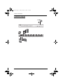
1
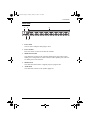
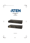
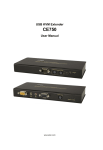
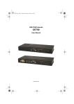
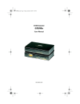
VS-1601.book Page i Tuesday, January 16, 2007 12:15 PM User Manual VS1601 VS-1601.book Page ii Tuesday, January 16, 2007 12:15 PM VS1601 User Manual FCC Information This is an FCC Class A product. In a domestic environment this product may cause radio interference in which case the user may be required to take adequate measures. This equipment has been tested and found to comply with the limits for a Class A digital device, pursuant to Part 15 of the FCC Rules. These limits are designed to provide reasonable protection against harmful interference when the equipment is operated in a commercial environment. This equipment generates, uses and can radiate radio frequency energy and, if not installed and used in accordance with the instruction manual, may cause harmful interference to radio communications. Operation of this equipment in a residential area is likely to cause harmful interference in which case the user will be required to correct the interference at his own expense. RoHS This product is RoHS compliant. ii VS-1601.book Page iii Tuesday, January 16, 2007 12:15 PM VS1601 User Manual User Notice All information, documentation, and specifications contained in this manual are subject to change without prior notification by the manufacturer. The manufacturer makes no representations or warranties, either expressed or implied, with respect to the contents hereof and specifically disclaims any warranties as to merchantability or fitness for any particular purpose. Any of the manufacturer's software described in this manual is sold or licensed `as is'. Should the programs prove defective following their purchase, the buyer (and not the manufacturer, its distributor, or its dealer), assumes the entire cost of all necessary servicing, repair and any incidental or consequential damages resulting from any defect in the software. The manufacturer of this system is not responsible for any radio and/or TV interference caused by unauthorized modifications to this device. It is the responsibility of the user to correct such interference. The manufacturer is not responsible for any damage incurred in the operation of this system if the correct operational voltage setting was not selected prior to operation. PLEASE VERIFY THAT THE VOLTAGE SETTING IS CORRECT BEFORE USE. iii VS-1601.book Page iv Tuesday, January 16, 2007 12:15 PM VS1601 User Manual Safety Instructions General Read all of these instructions. Save them for future reference. Follow all warnings and instructions marked on the device. Do not place the device on any unstable surface (cart, stand, table, etc.). If the device falls, serious damage will result. Do not use the device near water. Do not place the device near, or over, radiators or heat registers. The device cabinet is provided with slots and openings to allow for adequate ventilation. To ensure reliable operation, and to protect against overheating, these openings must never be blocked or covered. The device should never be placed on a soft surface (bed, sofa, rug, etc.) as this will block its ventilation openings. Likewise, the device should not be placed in a built in enclosure unless adequate ventilation has been provided. Never spill liquid of any kind on the device. Unplug the device from the wall outlet before cleaning. Do not use liquid or aerosol cleaners. Use a damp cloth for cleaning. The device should be operated from the type of power source indicated on the marking label. If you are not sure of the type of power available, consult your dealer or local power company. The device is equipped with a 3-wire grounding type plug. This is a safety feature. If you are unable to insert the plug into the outlet, contact your electrician to replace your obsolete outlet. Do not attempt to defeat the purpose of the grounding-type plug. Always follow your local/national wiring codes. Do not allow anything to rest on the power cord or cables. Route the power cord and cables so that they cannot be stepped on or tripped over. If an extension cord is used with this device make sure that the total of the ampere ratings of all products used on this cord does not exceed the extension cord ampere rating. Make sure that the total of all products plugged into the wall outlet does not exceed 15 amperes. To help protect your system from sudden, transient increases and decreases in electrical power, use a surge suppressor, line conditioner, or un-interruptible power supply (UPS). iv VS-1601.book Page v Tuesday, January 16, 2007 12:15 PM VS1601 User Manual Position system cables and power cables carefully; Be sure that nothing rests on any cables. When connecting or disconnecting power to hot-pluggable power supplies, observe the following guidelines: Install the power supply before connecting the power cable to the power supply. Unplug the power cable before removing the power supply. If the system has multiple sources of power, disconnect power from the system by unplugging all power cables from the power supplies. Never push objects of any kind into or through cabinet slots. They may touch dangerous voltage points or short out parts resulting in a risk of fire or electrical shock. Do not attempt to service the device yourself. Refer all servicing to qualified service personnel. If the following conditions occur, unplug the device from the wall outlet and bring it to qualified service personnel for repair. The power cord or plug has become damaged or frayed. Liquid has been spilled into the device. The device has been exposed to rain or water. The device has been dropped, or the cabinet has been damaged. The device exhibits a distinct change in performance, indicating a need for service. The device does not operate normally when the operating instructions are followed. Only adjust those controls that are covered in the operating instructions. Improper adjustment of other controls may result in damage that will require extensive work by a qualified technician to repair. v VS-1601.book Page vi Tuesday, January 16, 2007 12:15 PM VS1601 User Manual Rack Mounting Before working on the rack, make sure that the stabilizers are secured to the rack, extended to the floor, and that the full weight of the rack rests on the floor. Install front and side stabilizers on a single rack or front stabilizers for joined multiple racks before working on the rack. Always load the rack from the bottom up, and load the heaviest item in the rack first. Make sure that the rack is level and stable before extending a device from the rack. Use caution when pressing the device rail release latches and sliding a device into or out of a rack; the slide rails can pinch your fingers. After a device is inserted into the rack, carefully extend the rail into a locking position, and then slide the device into the rack. Do not overload the AC supply branch circuit that provides power to the rack. The total rack load should not exceed 80 percent of the branch circuit rating. Ensure that proper airflow is provided to devices in the rack. Do not step on or stand on any device when servicing other devices in a rack. vi VS-1601.book Page vii Tuesday, January 16, 2007 12:15 PM VS1601 User Manual Package Contents Basic Package The basic VS1601 package consists of: 1 VS1601 Video Switch with Standard Rack Mounting Kit 1 VGA/Audio Cable (1.8 m) 1 IR Remote Control Unit 1 External IR receiver (1.8m) 1 Power Adapter (AC 9V) 1 User Manual* 1 Quick Start Guide Check to make sure that all the components are present and that nothing got damaged in shipping. If you encounter a problem, contact your dealer. Read this manual thoroughly and follow the installation and operation procedures carefully to prevent any damage to the unit, and/or any of the devices connected to it. * Features may have been added to the VS1601 since this manual was printed. Please visit our website to download the most up to date version of the manual. © Copyright 2006 ATEN® International Co., Ltd. Manual Part No. PAPE-1293-100G Printing Date: 01/2007 ATEN and the ATEN logo are registered trademarks of ATEN International Co., Ltd. All rights reserved. All other brand names and trademarks are the registered property of their respective owners. vii VS-1601.book Page viii Tuesday, January 16, 2007 12:15 PM VS1601 User Manual Contents FCC Information . . . . . . . . . . . . . . . . . . . . . . . . . . . . . . . . . . . . . . . . . . . . . ii User Notice . . . . . . . . . . . . . . . . . . . . . . . . . . . . . . . . . . . . . . . . . . . . . . . . . iii Safety Instructions . . . . . . . . . . . . . . . . . . . . . . . . . . . . . . . . . . . . . . . . . . .iv General . . . . . . . . . . . . . . . . . . . . . . . . . . . . . . . . . . . . . . . . . . . . . . . . .iv Rack Mounting . . . . . . . . . . . . . . . . . . . . . . . . . . . . . . . . . . . . . . . . . . .vi Package Contents . . . . . . . . . . . . . . . . . . . . . . . . . . . . . . . . . . . . . . . . . . vii Basic Package . . . . . . . . . . . . . . . . . . . . . . . . . . . . . . . . . . . . . . . . . . vii About this Manual . . . . . . . . . . . . . . . . . . . . . . . . . . . . . . . . . . . . . . . . . . . .ix Conventions . . . . . . . . . . . . . . . . . . . . . . . . . . . . . . . . . . . . . . . . . . . . . . . . x Getting Help . . . . . . . . . . . . . . . . . . . . . . . . . . . . . . . . . . . . . . . . . . . . . . . . x 1. Introduction Overview. . . . . . . . . . . . . . . . . . . . . . . . . . . . . . . . . . . . . . . . . . . . . . . . . . . 1 Features . . . . . . . . . . . . . . . . . . . . . . . . . . . . . . . . . . . . . . . . . . . . . . . . . . . 1 System Requirements . . . . . . . . . . . . . . . . . . . . . . . . . . . . . . . . . . . . . . . . 2 Load Device . . . . . . . . . . . . . . . . . . . . . . . . . . . . . . . . . . . . . . . . . . . . . 2 Source Device(s). . . . . . . . . . . . . . . . . . . . . . . . . . . . . . . . . . . . . . . . . . 2 Cables . . . . . . . . . . . . . . . . . . . . . . . . . . . . . . . . . . . . . . . . . . . . . . . . . . 2 Components . . . . . . . . . . . . . . . . . . . . . . . . . . . . . . . . . . . . . . . . . . . . . . . . 3 Front View . . . . . . . . . . . . . . . . . . . . . . . . . . . . . . . . . . . . . . . . . . . . . . . 3 Rear View . . . . . . . . . . . . . . . . . . . . . . . . . . . . . . . . . . . . . . . . . . . . . . . 4 IR Remote Control Unit . . . . . . . . . . . . . . . . . . . . . . . . . . . . . . . . . . . . . 5 2. Hardware Setup Installation. . . . . . . . . . . . . . . . . . . . . . . . . . . . . . . . . . . . . . . . . . . . . . . . . . 6 Installation Diagram . . . . . . . . . . . . . . . . . . . . . . . . . . . . . . . . . . . . . . . 7 3. Operation Port Selection . . . . . . . . . . . . . . . . . . . . . . . . . . . . . . . . . . . . . . . . . . . . . . . 8 Manual Port Up / Port Down . . . . . . . . . . . . . . . . . . . . . . . . . . . . . . . . . 8 IR Port Up / Port Down . . . . . . . . . . . . . . . . . . . . . . . . . . . . . . . . . . . . . 8 IR Direct Port Selection. . . . . . . . . . . . . . . . . . . . . . . . . . . . . . . . . . . . . 8 Appendix Specifications . . . . . . . . . . . . . . . . . . . . . . . . . . . . . . . . . . . . . . . . . . . . . . . 9 Troubleshooting . . . . . . . . . . . . . . . . . . . . . . . . . . . . . . . . . . . . . . . . . . . . 10 Limited Warranty. . . . . . . . . . . . . . . . . . . . . . . . . . . . . . . . . . . . . . . . . . . . 10 viii VS-1601.book Page ix Tuesday, January 16, 2007 12:15 PM VS1601 User Manual About this Manual This User Manual is provided to help you get the most from your VS1601 system. It covers all aspects of installation, configuration and operation. An overview of the information found in the manual is provided below. Introduction, introduces you to the VS1601 system. Its purpose, features and benefits are presented, and its front and back panel components are described. Hardware Setup, describes how to set up your installation. Operation, explains the fundamental concepts involved in operating the VS1601. An Appendix, provides specifications and other technical information regarding the VS1601. ix VS-1601.book Page x Tuesday, January 16, 2007 12:15 PM VS1601 User Manual Conventions This manual uses the following conventions: Monospaced Indicates text that you should key in. [] Indicates keys you should press. For example, [Enter] means to press the Enter key. If keys need to be chorded, they appear together in the same bracket with a plus sign between them: [Ctrl+Alt]. 1. Numbered lists represent procedures with sequential steps. ♦ Bullet lists provide information, but do not involve sequential steps. → Indicates selecting the option (on a menu or dialog box, for example), that comes next. For example, Start → Run means to open the Start menu, and then select Run. Indicates critical information. Getting Help If you need to contact ATEN technical support with a problem, visit or website at www.aten.com. x VS-1601.book Page 1 Tuesday, January 16, 2007 12:15 PM Chapter 1 Introduction Overview The VS1601 Video Switch is a modern control unit that allows you to conveniently display the video output of 16 separate computer systems on a single monitor, or via a multimedia projector - thereby eliminating the unnecessary expense of purchasing a separate monitor for each computer. The VS1601 is perfect for server rooms. The VS1601 features stereo audio support; easy computer selection via pushbuttons; intelligent infrared (IR) remote control; and electronic switching technology for reliability and durability. The VS1601 is rack mountable and occupies 1U of space; furthermore, it saves extra monitor space, extra power costs, and eliminates the inconvenience and wasted effort involved in constantly moving around from one computer to another. Features Supports up to 250 MHz bandwidth. High resolution video up to 1920 x 1440 @ 60Hz; DDC; DDC2; DDC2B Supports VGA, SVGA, XVGA and MultiSync monitors. Stereo audio support External IR receiver (1.8m) for maximum efficiency and convenience. Fast and convenient computer selection via push buttons or infrared (IR) remote control. Maintains high video resolution over long distances. Duplicates and enhances video signal up to 65m (max.) All metal exterior case. Designed for enterprise use – 1U in size and rack mountable. 1 VS-1601.book Page 2 Tuesday, January 16, 2007 12:15 PM 1. Introduction System Requirements Load Device One VGA, SVGA, XGA, or Multisync compatible analog monitor, with a standard PC high density cable having a 15 pin HDB type male connector One mini stereo audio input jack (optional) Source Device(s) One VGA, SVGA, XGA, or Multisync analog video card having a standard PC 15 pin HDB type female connector per computer One mini stereo audio output jack (optional) Cables A video cable with one male and one female HDB-15 connector at each end for each computer you will be installing. An audio cable with a Mini Stereo Jack. Note: One (1) VGA/audio cable is supplied with this unit. 2 VS-1601.book Page 3 Tuesday, January 16, 2007 12:15 PM 1. Introduction Components Front View 1 2 4 3 5 1. Port LEDs The LED lights ORANGE to indicate the computer connected to its corresponding port is Online. The LED lights GREEN to indicate the computer connected to its corresponding port is the one that is currently selected. 2. Port Selection Switches Press this button to switch the video focus. Port Down – switches the video focus to the computer previous to the current one. Port Up – switches the video focus to the computer subsequent to the current one. 3. IR Sensor This is the integrated IR receiver for the VS1601 remote control unit. 4. VGA Display On / Off LED The LED lights Blue to indicate the unit's VGA display is ON. 5. External IR Receiver Port The external IR Receiver has an attached cable that allows it to be placed anywhere up to 1.8m from the VS1601 switch. The cable from the external IR Receiver plugs in here. 3 VS-1601.book Page 4 Tuesday, January 16, 2007 12:15 PM 1. Introduction Rear View 1 2 4 3 5 1. Power Jack The AC Power Adapter cable plugs in here. 2. Power Switch Press this switch to turn ON or OFF the VS1601. 3. Media Port Section The cables that connect to the computer media ports plug in here. Each media port is comprised of a VGA connector and a speaker jack. There are 16 media ports on the VS1601. 4. Monitor Port The cable from the monitor or digital projector plugs in here. 5. Audio Jack The cable that connects to the speaker plugs her. 4 VS-1601.book Page 5 Tuesday, January 16, 2007 12:15 PM 1. Introduction IR Remote Control Unit Note: The VS1601's remote control unit comes packaged in protective plastic film. Before operating the remote control unit, please remove this protective film. 1 2 3 1. Port Up / Port Down These buttons function in a similar manner to the Port Up / Port Down buttons on the main unit. Press these buttons to switch the video focus to the NEXT or PREVIOUS computer on the installation. 2. Port Selection The numbers correspond to the video ports on the main unit. Press a pushbutton (1 to 16) to switch the video focus to the computer connected to its corresponding port. Note: Switching ports requires a few seconds to complete. To switch the video focus immediately, press Enter after selecting a port. 3. Enter Press this pushbutton after selecting a video port (1 to 16) to quickly switch the video focus to the corresponding port. 5 VS-1601.book Page 6 Tuesday, January 16, 2007 12:15 PM Chapter 2 Hardware Setup 1. Important safety information regarding the placement of this device is provided on page iv. Please review it before proceeding. 2. Make sure that power to all the devices you will be connecting up have been turned off. You must unplug the power cords of any computers that have the Keyboard Power On function. Installation Installation is quick and easy. See Installation Diagram, page 7 for reference. Note: Before starting the installation, make sure that power to all the devices to be connected to the VS1601 is turned off. 1. Plug the monitor or digital projector cable into the unit's Monitor port. 2. Connect speakers to the unit’s audio output port. 3. Plug one end of a video cable (refer to the System Requirements section on p. 2), into any available video port on the unit; plug the other end into the computer's video output port. Note: One video cable is supplied with this unit. Additional cables require an extra purchase. 4. Use a male/male audio cable to connect the computer’s speaker output port with the audio input port of the video port selected in step 4. 5. Repeat steps 3 and 4 for each computer you wish to install. 6. Plug the power adapter (supplied with this package) into an AC source, and then plug the power adapter cable into the unit's Power Jack. 7. Plug the IR Receiver cable into the IR Receiver port at the front of the main unit (this step is optional). 8. Power On all equipment. 6 VS-1601.book Page 7 Tuesday, January 16, 2007 12:15 PM VS1601 User Manual Installation Diagram 7 3 4 6 1 7 2 VS-1601.book Page 8 Tuesday, January 16, 2007 12:15 PM Chapter 3 Operation Port Selection Manual Port Up / Port Down Use the Port Up and Port Down pushbuttons, located on the VS1601 unit, to cycle the video focus to the port you want. The selected port’s LED lights GREEN to indicate that the computer connected to its corresponding port has the video focus. IR Port Up / Port Down The video focus can also be cycled among the computers using the Port Up and Port Down buttons of the IR Remote Control Unit (see page 5). IR Direct Port Selection Instead of cycling among the individual computers one-by-one, a computer can be directly selected by pushing the button on the Remote Control Unit that corresponds to its port number (1-16) on the main unit. The selected port's LED lights GREEN to indicate that the computer connected to its corresponding port has the video focus. Note: The VS1601's Remote Control Unit has a maximum infrared-signal range of up to10 meters. For optimum performance make sure that there is a clear line-of-site between the handset and the receiver. 8 VS-1601.book Page 9 Tuesday, January 16, 2007 12:15 PM Appendix Specifications Function Computer Connections Port Selection Connectors Video In 16 x HDB-15 Male (Blue) Audio In 16 x Mini Stereo Jack Female (Green) Video Out 1 x HDB-15 Female (Blue) Audio Out 1 x Mini Stereo Jack Female (Green) Power Selected 16 (Green) 1 (Blue) Power 1 x Rocker Port Up 1 x Pushbutton Port Down 1 x Pushbutton 1 Video 1920 x 1440 @ 60Hz (max); DDC2B Signal Range 65m Power Consumption Physical Properties 1 x AC Jack (Black) 16 (Orange) IR Sensor Environment 1 x Mini Stereo Jack (Female) On Line Video Out Display On/Off Switches 16 Pushbutton; IR Remote Control IR LEDs VS1601 Operating Temp. AC 9V, 2.5W 0 – 50o C Storage Temp. -20 – 60o C Humidity 0 – 80% RH Housing Metal Weight 2.60kg Dimensions 43.30 x 16.00 x 4.40 cm (L x W x H) 9 VS-1601.book Page 10 Tuesday, January 16, 2007 12:15 PM VS1601 User Manual Troubleshooting Problem There are ghost images on the external monitor. Solution The distance between the external console and the VS1601 is too great. The maximum VGA cable distance should not exceed 20m and, in some cases, may need to be shorter. Replace the VGA cable with one of an appropriately short length. Limited Warranty IN NO EVENT SHALL THE DIRECT VENDOR'S LIABILITY EXCEED THE PRICE PAID FOR THE PRODUCT FROM DIRECT, INDIRECT, SPECIAL, INCIDENTAL, OR CONSEQUENTIAL DAMAGES RESULTING FROM THE USE OF THE PRODUCT, DISK, OR ITS DOCUMENTATION. The direct vendor makes no warranty or representation, expressed, implied, or statutory with respect to the contents or use of this documentation, and especially disclaims its quality, performance, merchantability, or fitness for any particular purpose. The direct vendor also reserves the right to revise or update the device or documentation without obligation to notify any individual or entity of such revisions, or update. For further inquiries, please contact your direct vendor. 10