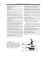
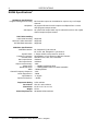
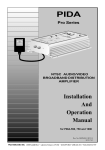
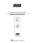
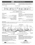
1
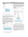
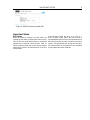
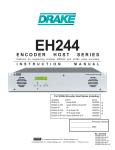
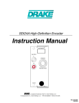
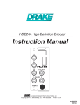
EH244 Encoder Host
INSTRUCTION MANUAL
EH244 ENCODER HOST
ENTER
ENCODER
SELECT
is a registered trademark of R. L. Drake Holdings, LLC
© Copyright 2012 R. L. Drake Holdings, LLC
P/N: 3852568-4-2012
2
TABLE OF CONTENTS AND CAUTION STATEMENTS
Contents
Caution Statements
2
Important Safety Instructions
3
Specifications
4
General Description
5
Installation and Mounting
5
Configuration
6
Front Panel Configuration . . . . . . . . . . . . . . . . . . . . . . . . . . . . . . . . . . . . 6
Ethernet Control Interface Configuration . . . . . . . . . . . . . . . . . . . . . . . . . . . . 7
Important Notes
9
Warranty
11
Caution Statements
WARNING: TO PREVENT FIRE OR
ELECTRICAL SHOCK, DO NOT
EXPOSE TO RAIN OR MOISTURE
CAUTION
RISK OF ELECTRIC SHOCK
DO NOT OPEN
A product and cart combination should be
moved with care. Quick stops, excessive
force and uneven surfaces may cause the
product and cart combination to overturn.
!
CAUTION: TO REDUCE THE RISK OF ELECTRIC
SHOCK, DO NOT REMOVE COVER. NO USERSERVICEABLE PARTS INSIDE. REFER SERVICING
TO QUALIFIED PERSONNEL
!
The lightning flash with arrow head symbol,
within an equilateral triangle, is intended to
alert the user to the presence of uninsulated
"dangerous voltage" within the product's
enclosure that may be of sufficient
magnitude to constitute a risk of electric
shock to persons.
The exclamation point within an equilateral
triangle is intended to alert the user to the
presence of important operating and
maintenance (servicing) instructions in the
literature accompanying the product.
WARNING:
TO REDUCE THE RISK OF FIRE OR ELECTRIC SHOCK, DO NOT
EXPOSE THIS PRODUCT TO RAIN OR MOISTURE.
DO NOT OPEN THE CABINET, REFER SERVICING TO QUALIFIED
PERSONNEL ONLY.
CAUTION:
TO PREVENT ELECTRIC SHOCK, DO NOT USE THIS (POLARIZED)
PLUG WITH AN EXTENSION CORD RECEPTACLE OR OTHER OUTLET
UNLESS THE BLADES CAN BE FULLY INSERTED TO PREVENT BLADE
EXPOSURE.
ATTENTION:
POUR PREVENIR LES CHOCS ELECTRIQUES, NE PAS UTILISER
CETTE FICHE POLARISEE AVEC UN PROLONGATEUR, UNE PRISE
DE COURANT OU UNE AUTRE SORTIE DE COURANT, SAUF SI LES
LAMES PEUVENT ETRE INSEREES A FOND SANS EN LAISSER
AUCUNE PARTIE A DECOUVERT.
IMPORTANT SAFETY INSTRUCTIONS
1 Read Instructions: All the safety and operating instructions should be
read before the product is operated.
2 Retain Instructions: The safety and operating instructions should be
retained for future reference.
3 Heed Warnings: All warnings on the product and in the operating instructions should be adhered to.
4 Follow Instructions: All operating and use instructions should be followed.
5 Cleaning: Unplug this product from the wall outlet before cleaning. Do
not use liquid cleaners or aerosol cleansers. Use a damp cloth for cleaning.
6 Attachments Do not use attachments that are not recommended by the
product manufacturer as they may cause hazards.
7 Water and Moisture Do not use this product near water—for example,
near a bathtub, wash bowl, kitchen sink or laundry tub; in a wet basement; or near a swimming pool; and the like.
8 Accessories Do not place this product on an unstable cart, stand, tripod, bracket, or table. The product may fall, causing serious injury to
a child or adult, and serious damage to the product. Use only with a
cart, stand, tripod, bracket, or table recommended by the manufacturer,
or sold with the product. Any mounting of the product should follow the
manufacturer's instructions, and should use a mounting accessory recommended by the manufacturer.
9 A product and cart combination should be moved with care. Quick stops,
excessive force, and uneven surfaces may cause the product and cart
combination to overturn.
10 Ventilation Slots and openings in the cabinet are provided for ventilation and to ensure reliable operation of the product and to protect it from
overheating, and these openings must not be blocked or covered. The
openings should never be blocked by placing the product on a bed, sofa,
rug, or similar surface. This product should not be placed in a built-in installation such as bookcase or rack unless proper ventilation is provided
or the manufacturer's instructions have been adhered to.
11 Power Sources This product should be operated only from the type of
power source indicated on the marking label. If you are not sure of the
type of power supplied to your home, consult your product dealer or local
power company. For products intended to operate from battery power,
or other sources, refer to the operating instructions.
12 Grounding or Polarization This product may be equipped with a polarized alternating-current line plug (a plug having one blade wider than
the other). This plug will fit into the power outlet only one way. This is
a safety feature. If you are unable to insert the plug fully into the outlet,
try reversing the plug. If the plug should still fail to fit, contact your electrician to replace your obsolete outlet. Do not defeat the safety purpose
of the polarized plug. Alternate Warnings – If this product is equipped
with a three-wire grounding- type plug, a plug having a third (grounding)
pin, the plug will only fit into a grounding-type power outlet. This is a
safety feature. If you are unable to insert the plug into the outlet, contact
your electrician to replace your obsolete outlet. Do not defeat the safety
purpose of the grounding-type plug.
13 Mise à la terre ou Polarisation Cet appareil est équipé avec un cordon
d'alimentation à trois fils. Il est a brancher sur une prise ayant un connecteur a la terre. Assurez-vous que la connection a la terre ne manque
pas.
3
14 Power-Cord Protection Power-supply cords should be routed so that
they are not likely to be walked on or pinched by items placed upon or
against them, paying particular attention to cords at plugs, convenience
receptacles, and the point where they exit from the product.
15 Lightning For added protection for this product during a lightning storm,
or when it is left unattended and unused for long periods of time, unplug it
from the wall outlet and disconnect the antenna or cable system. This will
prevent damage to the product due to lightning and power-line surges.
16 Power Lines An outside antenna system should not be located in the
vicinity of overhead power lines, other electric light or power circuits,
where it can fall into such power lines or circuits. When installing an
outside antenna system, extreme care should be taken to keep from
touching such power lines or circuits as contact with them may be fatal.
17 Overloading Do not overload wall outlets, extension cords, or integral
convenience receptacles as this can result in a risk of fire or electric
shock.
18 Object and Liquid Entry Never push objects of any kind into this product through openings as they may touch dangerous voltage points or
short-out parts that could result in a fire or electric shock. Never spill
liquid of any kind on the product.
19 Servicing Do not attempt to service this product yourself as opening or
removing covers may expose you to dangerous voltage or other hazards.
Refer all servicing to qualified service personnel.
20 Damage Requiring Service Unplug this product from the wall outlet and
refer servicing to qualified service personnel under the following conditions:
a) When the power-supply cord or plug is damaged,
b) If liquid has been spilled, or objects have fallen into the product,
c) If the product has been exposed to rain or water,
d) If the product does not operate normally by following the operating instructions.
Adjust only those controls that are covered by the operating instructions
as an improper adjustment of other controls may result in damage and
will often require extensive work by a qualified technician to restore the
product to its normal operation, e. If the product has been dropped or
damaged in any way, and f. When the product exhibits a distinct change
in performance—this indicates a need for service.
21 Replacement Parts When replacement parts are required, be sure the
service technician has used replacement parts specified by the manufacturer or have the same characteristics as the original part. Unauthorized
substitutes may result in fire, electric shock or other hazards.
22 Safety Check Upon completion of any service or repairs to this product,
ask the service technician to perform safety checks to determine that the
product is in proper operating condition.
23 Wall or Ceiling Mounting The product should be mounted to a wall or
ceiling only as recommended by the manufacturer.
24 Heat The product should be situated away from heat sources such as
radiators, heat registers, stoves, or other products (including amplifiers)
that produce heat.
ANTENNA
LEAD IN
WIRE
NOTE TO CABLE INSTALLER:
THIS REMINDER IS PROVIDED TO CALL THE
CATV SYSTEM INSTALLER'S ATTENTION TO ARTICLE 820-40 OF THE NEC THAT PROVIDES GUIDELINES FOR PROPER GROUNDING AND, IN PARTICULAR, SPECIFIES THAT THE CABLE GROUND
SHALL BE CONNECTED TO THE GROUNDING
SYSTEM OF THE BUILDING, AS CLOSE TO THE
POINT OF CABLE ENTRY AS PRACTICAL.
GROUND CLAMP
ANTENNA
DISCHARGE UNIT
(NEC SECTION 810-20)
ELECTRIC
SERVICE
EQUIPMENT
GROUNDING CONDUCTORS
(NEC SECTION 810-21)
GROUND CLAMPS
POWER SERVICE GROUNDING
ELECTRODE SYSTEM
(NEC ART 250, PART H)
NEC - NATIONAL ELECTRIC CODE
Example of antenna grounding as per National Electrical Code, ANSI/NFPA 70
4
SPECIFICATIONS
EH244 Specifications1
Multiplexer Specifications
Program Filtering and Grooming
Multiplexer
ASI Outputs
PSIP Table Handling
PSIP Table Rewriting
MGT/VCT Table Generation
SCTE18 EAS Generation
Modulator Specifications
Modulation Modes:
Symbol Rates:
Frequency Coverage:
Channel Plans:
Max Output Power:
Min Output Power:
Output Level Accuracy:
Phase Noise:
Broadband Noise:
MER:
Channel Frequency Response:
Carrier Suppression:
I/Q Imbalance:
Spurious Emissions:
Temperature Rating
Form Factor
Dimensions
Weight
Power Requirements
1
Each encoder output can be disabled or output to any or all output
channels
All programs directed to each output are multiplexed into a correct
multi-program transport stream
An optional ASI output board may be ordered that mirrors the 4 QAM
channel output transport streams
Supported
Supported
Supported
64, 256QAM ITU j.83 Annex B
16, 32, 64, 128, 256QAM ITU j.83 Annex A
1-7Msps variable, with presets for Annex B
54-1002MHz, up to 4 frequency-adjacent channels
Standard CATV, HRC, IRC, Broadcast
+54dBmV
+42dBmV
±2dB
< −108dBc/Hz@10kHz offset
< −75dBc@12MHz offset in a 6MHz bandwidth
>44dB equalized
<1dB
>80dB
<1 degree
<-60dBc
0-50C ambient
2RU 19'' rack enclosure
14.25''D x 3.5''H x 19'' W
9.5 lbs
90-260VAC 65W maximum
Specifications subject to change without notice or obligation.
DESCRIPTION / INSTALLATION
5
General Description
The R. L. Drake model EH244 encoder host is a
platform for supporting modular MPEG2 and H.264
video encoders, including the SDE24, HDE24, and
SDI24. The encoder host multiplexes the encoder
outputs into up to 4 output channels, configurable
via a front panel interface or ethernet web server.
The encoder includes provisions for emergency alert
services, using either video replacement or SCTE18
control messages.
The EH244 accepts up to 6 encoder modules, and allows each encoder's output program to be assigned
to any or all 4 output program streams. The EH244
can output on up to 4 frequency-adjacent QAM channels using an internal QAM modulator, and supports
optional ASI outputs that mirror the QAM program
streams.
Installation and Mounting
ASI OUTPUTS
1
2
ASI OUTPUT
3
4
IP OUTPUT
AC POWER
120 VAC, 60 Hz
65 WATTS
EAS
EAS
RF OUTPUT
ETHERNET
GND
Slot Numbers:
1
2
3
4
5
6
The EH244 is designed to be installed in a standard
19'' rack. All encoder and interface modules must
be installed in the EH244 chassis before power is
applied. DO NOT INSERT ENCODER MODULES
WHILE THE UNIT IS POWERED. Doing so will
void the EH244 and encoder warranties.
If the EH244 will be used as a master in a DTAenabled system, a Drake model ASII input module
must be installed in slot 6 (or slot 5, if the unit is an
EAS master using the Slot 6 or Slot 6 + SCTE
18 EAS modes). This ASII must be connected to
the output of a PC that is generating the DTA conThe input modules on the rear of the chassis are trol messages, created by the R. L. Drake DTA Control software. If the EH244 will be used as a slave
numbered 1-6, from left to right, if you look at the rear
in a DTA-enabled system, a Drake model ASII input
of the unit. Each encoder's program number will be
assigned based on its slot location (slot 1 will provide module must be installed in slot 6, and connected
programs 1 and 2; slot 2 will provide programs 3 and to the previous EH24/EH244 ASI Output. For slave
4; etc). HDE24 and SDI24 encoders only provide systems using both DTA- and EAS-modes, a single
odd-numbered programs, as each of these encoders ASII input module will perform both functions.
is a single-input encoder.
Connect the AC line cord to an appropriate
If the EH244 will be used in an EAS-enabled sys- 120-240V, 50/60Hz AC power source. The EH244
tem, and the unit will be used as the master EAS unit will always be powered and running as long as it is
in Slot 6 or Slot 6 + SCTE 18 modes, a Drake connected to its power source.
model SDE24EAS input module must be installed in
slot 6 of the chassis. If the EH244 is configured for
slave EAS modes Slot 6 or Slot 6 + SCTE 18,
a Drake model ASII module must be installed in slot
6, and wired to the ASI Output port of the previous
EH24/EH244 in the chain.
Connect the RF output to a 75-ohm cable system.
Optionally, connect the EAS terminals to the output
of an EAS receiver to enable emergency alerts. Connect the ethernet control interface port to a secured
network or VPN for remote system configuration.
6
CONFIGURATION
Configuration
The EH244 is configured by either the front-panel interface or the ethernet-connected web server interface. When the unit is first installed, the front-panel
should be used to configure the unit's IP settings before using the ethernet controls; most configuration
of the unit may be performed from the front panel if
the operator chooses to do so.
Front Panel Configuration
The front panel can display several useful status
messages that can be selected by using the buttons to the right of the LCD. When pressing the button above the ENTER button, the LCD display will
cycle between: the currently-installed firmware version; the IP address currently assigned to the ethernet control interface; and the MAC address of the
ethernet control interface. When pressing the button
below the ENTER button, the LCD display will cycle
between the output channel bit-rates of the 4 outputs.
To use the front panel to change settings, press one
of the two buttons labeled ENCODER SELECT until
the LCD display says EH244, and then hold in the
center button labeled ENTER for about two seconds
(until the LCD display begins to blink). At this point,
you are in configuration mode, and you can use the
two buttons on either side of the ENTER button to
switch between settings on the unit; pressing the
buttons above or below the ENTER button will cycle
through the valid values for the setting currently displayed on the LCD. When all configuration is complete, pressing the ENTER button again will save all
settings and return the front panel to its normal mode.
The following settings are available from the front
panel:
· USER NAME: Variable – this sets the username
for the ethernet control interface authorization; this
field is case-sensitive
· PASSWORD: Variable – this sets the password
for the ethernet control interface authorization; this
field is case-sensitive
· HOST NAME: Variable – this sets the display
hostname for the ethernet control interface
· DHCP: ENABLED, DISABLED – this configures the
ethernet control interface to use DHCP for its IP configuration settings when enabled, or to use the static
IP configuration that follows when disabled
· IP ADDRESS: Variable – this sets the ethernet
control interface's static IP address when DHCP is
disabled
· SUBNET MASK: Variable – this sets the eth-
ernet control interface's IP subnet netmask when
DHCP is disabled
· GATEWAY ADDRESS: Variable – this sets the
default gateway for the ethernet control interface
when DHCP is disabled
· DTA/EAS CONTROL: DISABLED, MASTER,
SLAVE – this sets the unit's EAS and DTA control
mode. When Master, the unit is the first in the daisy
chain of Drake devices; when slave, the unit is not
the first in the daisy chain
· DTA MODE: DISABLED, ENABLED – this enables
the DTA control feature of the unit (which allows
SCTE65 control messages to be passed out to
low-cost DTA settop boxes for channel lineup and
firmware update purposes)
· EAS MODE: DISABLED, MODULE 6, SCTE
18, MODULE 6+SCTE 18 – this sets the EAS
mode in use. MODULE 6 replaces all video and audio
streams with the input from the EAS encoder when
an EAS alert is active. SCTE 18 sends the SCTE 18
EAS control messages when an EAS alert is active.
MODULE 6+SCTE 18 performs both actions when
an EAS alert is active
· EAS RF CHANNEL: Channel number – this configures the SCTE 18 force-tuning RF channel number that every receiver should tune to during an EAS
alert
· EAS MODULATION: QAM-64B, QAM-256B – this
configures the SCTE 18 force-tuning channel modulation method that every receiver should tune to during an EAS alert
· EAS MPEG PROG #: Program number – this
configures the SCTE 18 force-tuning MPEG program
number that every receiver should tune to during an
EAS alert
· EAS MAJOR CHAN: Major number – this sets
the PSIP major channel number of the SCTE 18
force-tuning channel
· EAS MINOR CHAN: Minor number – this sets
the PSIP minor channel number of the SCTE 18
force-tuning channel
· PACKET DELAY: 0-200 usec – this sets the delay interval between encoder output packets, in microseconds. This setting may be used to enable
older settop boxes with small decoder buffers to work
with the SDE24 encoder's output stream. If needed,
a setting around 70-100usec works well, but this setting must be tweaked for each encoder based on the
deployed settop boxes
· OUTPUTx BITRATE: Variable – when a specific
output is not being used for generating a QAM channel, the output bitrate may be varied to allow for more
CONFIGURATION
flexible deployments. This allows the optional ASI
outputs to run at higher than the standard QAM data
rates (or lower, if they will be used in conjunction with
an external lower-bitrate modulator)
· ENCODER x: OUTPUT - x – this setting allows
each encoder's output program to be assigned to any
or all of the output channels, by cycling through all of
the options
· MGT/VCT: DISABLED, CVCT, TVCT – this sets
the MGT/VCT table style to the cable (CVCT) or
broadcast (TVCT) standard as needed by the deployment
· VIRTUAL+MPEG #s: DEFAULT, USER DEFINED
– this setting allows the operator to override
the default virtual channel numbers (which default to RF_channel_number - encoder_index_number). The user-defined settings must be
set from the ethernet control interface
· QAM OUTPUT x: ENABLED, DISABLED – this allows each individual QAM channel to be disabled individually
· QAM MODE: QAM-256B, QAM-64B, QAM-256A,
QAM-128A, QAM-64A, QAM-32A, QAM-16A –
this sets the output modulation type for all 4 QAM
channels
· QAM SYMRATE: DEFAULT, variable – this
sets the symbol rate for all 4 QAM modulators.
The DEFAULT choice only exists for QAM-256B and
QAM-64B, for which default symbol rates exist
· INTERLEAVER: Variable – this sets the interleaver configuration when the unit is in QAM-256B
or QAM-64B modes
· OUTPUT FORMAT: NORMAL, STANDBY, CW –
this sets the modulator format (CW for adjusting system carrier levels, STANDBY to turn off all 4 modulators)
· OUTPUT
CHANMAP:
CATV, BROADCAST,
HRC, IRC – this sets the RF channel number mapping style
· OUTPUT CHANNELS: Variable – this selects
the 4 frequency-adjacent RF channels that the QAM
modulator will use for QAM outputs 1-4
· RF OUT: 42-54dBmV – this sets the output level of
all 4 QAM outputs
Ethernet Control Interface
Configuration
There are two options for the ethernet control interface setup. If your ethernet network has a DHCP
server available, and you would like to use that to
7
configure the IP address of your EH244, you may
enable DHCP on the EH244. When the unit's front
panel has exited from configuration mode, you can
press the button above ENTER twice to view the IP
address that was discovered by DHCP.
If your network does not have a DHCP server, or you
choose not to use DHCP for configuration (this is the
recommended configuration, to avoid your EH244's
IP address changing in the future), you must obtain
an IP address, subnet mask, and default gateway
from your network administrator. Once you have determined the correct values for your particular network, set these values from the front panel.
Once the unit has an assigned IP address, you can
view and change its settings from a web browser. For
instance, if the unit's IP address were 10.0.0.1,
you would load http://10.0.0.1 in your web
browser to view and configure your EH244. The
username and password required to log into the unit
are both set from the front panel.
Once the EH244 web server has been loaded from
your browser, you should see the login dialog (see
Fig. 1). Enter the username and password (configurable via the front panel interface) and click LOG
IN.
Figure 1: EH244 Login Dialog
Once you are logged in to the EH244, you will be presented with the status page (see Figure 2). Along the
top edge of the page, there are five tabs listed; each
tab allows you to view and configure different parts of
the encoder host. The Status tab gives the overall
status of the whole unit, including firmware versions,
output bit-rates for all 4 outputs, output buffer usage,
and links to the relevant encoder manuals.
8
CONFIGURATION
The Output tab provides an interface to set all modulator output settings for the unit. A screenshot of this
tab is shown in Figure 4. This tab selects the DTA
and EAS modes, channel bitrates, QAM settings,
and the mapping from encoders to output channels.
For settings like the DTA/EAS options, more options
appear as you enable the sub-systems.
Figure 2: EH244 Status Tab
The Encoders tab allows you to set each encoder's
individual parameters. Select an encoder module
from the drop-down menu, and the appropriate setting selections will be displayed.
The Channels tab provides an interface to configure
the virtual channel mappings for this encoder host.
If PSIP is enabled, this page will display a screen
that looks like Figure 3; for each encoder output, the
MPEG program number can be modified, along with
the Major and Minor channel numbers. If one-part
virtual channel numbers are desired, the PSIP Mode
must be set to CVCT and the Minor number for each
channel should be set to 0.
Figure 4: EH244 Output Tab
The Firmware Update tab allows you to update all
of the firmware on the unit with a single upload (see
Figure 5). Once you have received a new firmware
image for the unit, click on the Choose File button and select the provided firmware; click Upload
to initiate the update. After a few minutes, the unit
will restart with the new firmware. If a power loss
occurs during update, the unit will recover automatically – if the firmware upload was not completed, it
may be necessary to re-initiate the update process
once power is restored.
Figure 3: EH244 Channels Tab
IMPORTANT NOTES
9
Figure 5: EH244 Firmware Update Tab
Important Notes
EAS Notes
When the EH244 is running in an EAS mode, the
emergency alert state is entered when the two terminals on the rear panel labeled EAS are connected
together via an external contact closure. EAS receivers should provide this contact closure output,
which will be wired to the terminal block on the rear
of the EH244.
If the EH244 is using the Slot 6 or Slot 6 +
SCTE 18 EAS modes, ensure that the bit rates of
the SDE24EAS encoder's two output channels are at
least as low as all of the other encoders in the entire
system. This guarantees that, during an EAS event,
the output bit-rates of the system are not exceeded
by the replacement video channels.
WARRANTY
11
Three Year Limited Warranty
R.L. DRAKE HOLDINGS LLC warrants to the original purchaser this product shall be free from defects in
material or workmanship for three (3) years from the date of original purchase.
During the warranty period R.L. DRAKE HOLDINGS LLC or an authorized Drake service facility will provide,
free of charge, both parts and labor necessary to correct defects in material and workmanship. At its option,
R.L. DRAKE HOLDINGS LLC may replace a defective unit.
To obtain such a warranty service, the original purchaser must:
1. Retain invoice or original proof of purchase to establish the start of the warranty period.
2. Notify R.L. DRAKE HOLDINGS LLC or the nearest authorized service facility, as soon as possible
after discovery of a possible defect, of:
a) the model and serial number,
b) the identity of the seller and the approximate date of purchase; and
c) A detailed description of the problem, including details on the electrical connection to associated
equipment and the list of such equipment.
3. Deliver the product to R.L. DRAKE HOLDINGS LLC or the nearest authorized service facility, or ship
the same in its original container or equivalent, fully insured and shipping charges prepaid.
Correct maintenance, repair, and use are important to obtain proper performance from this product. Therefore carefully read the Instruction Manual. This warranty does not apply to any defect that R.L. DRAKE
HOLDINGS LLC determines is due to:
1. Improper maintenance or repair, including the installation of parts or accessories that do not conform
to the quality and specifications of the original parts.
2. Misuse, abuse, neglect or improper installation.
3. Accidental or intentional damage.
All implied warranties, if any, including warranties of merchantability and fitness for a particular purpose,
terminate three (3) years from the date of the original purchase.
The foregoing constitutes R.L. DRAKE HOLDINGS LLC'S entire obligation with respect to this product, and
the original purchaser shall have no other remedy and no claim for incidental or consequential damages,
losses or expenses. Some states do not allow limitations on how long an implied warranty lasts or do
not allow the exclusions or limitation of incidental or consequential damages, so the above limitation and
exclusion may not apply to you.
This warranty gives you specific legal rights and you may also have other rights which vary from state to
state. This warranty shall be construed under the laws of Ohio.
For Service, contact:
R.L. DRAKE HOLDINGS LLC
230 Industrial Drive
Franklin, Ohio 45005 U.S.A.
Customer Service and Parts Telephone: +1 (937) 746-6990
Telefax: +1 (937) 806-1576
Web Site: http://www.rldrake.com
R.L. Drake Holdings LLC
230 Industrial Drive
Franklin, Ohio 45005 U.S.A.
Customer Service and Parts Telephone: +1 (937) 746-6990
Telefax: +1 (937) 806-1576
World Wide Web Site: http://www.rldrake.com