1
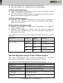
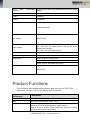
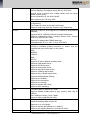
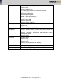
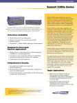
24-Port 10/100 L3 Switch
Model: 065-7434
Installation Guide
Revision A1
Table of Contents
OVERVIEW.......................................................................................................................... 2
PRODUCT FEATURES ........................................................................................................... 2
HARDWARE FEATURES ........................................................................................................ 4
Front Panel of 065-7434 Signamax 24-Port 10/100 L3 Switch .................................... 4
065-7434 Signamax 24-Port 10/100 L3 Switch System ................................................ 5
PRODUCT FUNCTIONS ......................................................................................................... 6
MODULES ............................................................................................................................ 9
POE15-8PSE MODULE....................................................................................................... 9
Ethernet Port Power Supply Control Module (POE15-8PSE) ...................................... 9
Connection of POE15-8PSE Interface Module ............................................................. 9
POWER MODULE (MANDATORY) ........................................................................................ 9
INSTALLATION PREPARATIONS ................................................................................. 11
SECURITY SUGGESTIONS ................................................................................................... 11
ENVIRONMENT REQUIREMENTS ......................................................................................... 11
Temperature and Humidity ...........................................................................................12
Dust-free Environment .................................................................................................12
Anti-static .....................................................................................................................13
Electromagnetic Environment Requirements ...............................................................13
Anti-lightning ...............................................................................................................14
CHECK SWITCH & ACCESSORIES .......................................................................................14
TOOLS & EQUIPMENT ........................................................................................................14
SYSTEM INSTALLATION ................................................................................................16
PREPARATIONS ...................................................................................................................16
Tools .............................................................................................................................16
Check Cabinet ..............................................................................................................16
Check Switch & Accessories ........................................................................................17
INSTALL SWITCH ................................................................................................................18
CONNECT CABLES .............................................................................................................19
Connect Console Port of Switch ..................................................................................19
GROUNDING WIRE CONNECTION .......................................................................................19
CONNECT POWER SUPPLY ..................................................................................................20
INSTALL MODULES ............................................................................................................21
Install POE15-8PSE Module .......................................................................................21
CABLES ...............................................................................................................................23
ETHERNET INTERFACE CABLE ...........................................................................................23
CABLES OF ETHERNET OPTICAL INTERFACE ......................................................................24
CONSOLE PORT CABLE ......................................................................................................24
RJ45-2BNC CABLE OF E1/T1 INTERFACE .........................................................................25
3I3O INTERFACE CABLE ....................................................................................................26
1
SIGNAMAX LLC • www.signamax.eu
Overview
065-7434 Signamax 24-Port 10/100 L3 Switch provides telecom-level
Ethernet access switches for operators. It supports next generation L2
and L3 features meets the requirements of customers for QoS, OAM, VPN,
Multi-service and Protection.
065-7434 Signamax 24-Port 10/100 L3 switch can help customers
develop IPTV, VoIP, VPN, wireless access and TDMoIP services. The high
integrated platform design meets the requirement of the customer that a
box provides rich physical interface and software features to reduce the
total cost (TCO) and operating expenses (OpEx).
065-7434 Signamax 24-Port 10/100 L3 Switch is the first in the world to
adopt dual power supply, high integrated E1/T1 interface, standard PoE,
and optical-electric Ethernet access on the access device. The operators
adopt it to be deployed in 2G/3G base station for developing multiservice access (wireless, VPN, and mobile) and completing the
reconstruction from TDM to IP.
Key Features:
Multi-service Ethernet switch with highest integrity
First to support dual power supply on access-level Ethernet
device
Supports perfect OAM protocol
Supports VPN services defined by MEF
50ms Ethernet service protection
Supports QinQ and selective QinQ
Supports UDLD and improves operation and maintenance
capabilities
Supports rich L2 and L3 protocols
Supports PoE and TDMoIP
Product Features
Multi-service access
2 SIGNAMAX LLC • www.signamax.eu
065-7434 Signamax 24-Port 10/100 L3 Switch supports the PoE power
supply of eight Ethernet interfaces for accessing wireless AP; provides
eight E1/T1 interfaces (TDMoIP) to meet the requirement that operators
access 2G base station service to IP network through E1/T1 interfaces,
and access the traditional TDM devices such as PBX, realizing unified IP
bearing; supports Ethernet fiber access for operators to access
commercial customers.
Perfect OAM
Currently, 065-7434 Signamax 24-Port 10/100 L3 Switch is one of
Ethernet access devices with perfect OAM. It can help operators to
manage the network more efficiently. In this way, the operation cost of
customers is reduced. The supported OAM standards include 802.1ag,
802.3ah and E-LMI.
Various VPN services
065-7434 Signamax 24-Port 10/100 L3 Switch passes MEF9 and MEF14
authentications of MEF, and supports the three VPN services including
EPL, EVPL and E-LAN defined by MEF to help operators open various VPN
services for customers.
Carriers-level UNI/NNI
Considering carriers, 065-7434 Signamax 24-Port 10/100 L3 Switch
defines all downstream interfaces as UNI interfaces. By default, UNI
interfaces are in close state and have no local switching function. And the
data on UNI interface is not sent to CPU, which ensures the device
security. By default, NNI interfaces are enabled, which is convenient for
carriers operate remotely.
50ms service protection
065-7434 Signamax 24-Port 10/100 L3 Switch adopts Ethernet ring
protection technology of Signamax, which can realize 50ms network
protection in single-ring, dual-ring/multi-ring, tangent-ring and
crossover-ring networking environments. In this way, the service
continuity of carriers is ensured and customer satisfaction is improved.
High reliability
065-7434 Signamax 24-Port 10/100 L3 Switch is one of the devices that
are first to support power redundancy in 1U box. Each power can access
different power supply network. In this way, the hot backup for power
modules (to prevent power supply fault) and the backup for power
supply network (to prevent the power-off of power company) are realized.
Advanced QoS
Each port of 065-7434 Signamax 24-Port 10/100 L3 Switch supports
eight queues and the queue scheduling policies such as SP, RR, WRR,
and WDRR; rich priority mappings including 802.1p802.1p,
802.1pCOS, DSCP802.1p, and DSCPDSCP; 64Kbps-based port
traffic rate restriction and carriers can limit the rate according to time
segment; Tail Drop and sRED packet loss arithmetic.
065-7434 Signamax 24-Port 10/100 L3 Switch supports single-rate
3 SIGNAMAX LLC • www.signamax.eu
three-color mode (srTCM) and dual-rate three-color mode (trTCM) to
meet the SLA requirements of carriers, including CIR, CBS and PIR.
L2/L3 multicast
065-7434 Signamax 24-Port 10/100 L3 Switch supports 1024 concurrent
multicast data flow; IGMP snooping and IGMP fast-adding/leaving
protocol.
Powerful anti-attack checking capability
065-7434 Signamax 24-Port 10/100 L3 Switch supports LAND, SYN Flood,
Smurf, Ping Flood, Teardrop and Ping of Death and defines the processing
policies for attack packets to ensure the device and network security.
Various authentication modes
065-7434 Signamax 24-Port 10/100 L3 Switch supports PPPOE and
802.1x access authentication modes, and Radius and TACAS+ protocols
to meet the requirements of carriers’ access authentication, authorization
and accounting for customers.
Hardware Features
Front Panel of 065-7434 Signamax 24Port 10/100 L3 Switch
Front panel of 065-7434 Signamax 24-Port 10/100 L3 Switch
The above are the front panels of 065-7434 Signamax 24-Port 10/100 L3
Switches. The meanings of the indicators on the panels are as follows:
SYS & PWR & FAN (system, power and fan indicators)
SYS: system status indicator, which flashes slowly after successful
system loading;
MASTER: system power indicator, which is on when the right (taking
the power panel as the reference side) 5V power works normally;
SLAVE: system power indicator, which is on when the left (taking the
power panel as the reference side) 5V power works normally;
FAN: system fan indicator, which is reserved for checking 3-wire fan
status (when the indicator is off, the fan works abnormally; when it
is on, the fan works normally); when the 2-wire fan is adopted, the
indicator is always on.
CON/AUX (console/AUX port)
4 SIGNAMAX LLC • www.signamax.eu
TXD: the indicator for console/AUX port sending data;
RXD: the indicator for console/AUX port receiving data;
FET0-23 (100M Ethernet port)
LINK: the indicator of Ethernet port link, which is always on when
the link of Ethernet port is set up;
ACT: the indicator of Ethernet port sending/receiving data, which is
flashes when data is being sent or received;
FEF8-23 (100M Ethernet port)
LINK/ACT: the indicator of Ethernet port link, which is always on
when the link of Ethernet port is set up and flashes when data is
being sent or received;
GE24-27 (WAN 1000M Ethernet port)
IN/OUT: the indicator of 3I3O alarm input/output; the software
control indicator is on;
LINK/ACT: the indicator of Ethernet port link, which is always on
when the link of Ethernet port is set up and flashes when data is
being sent or received;
The interfaces on the front panels of 065-7434 Signamax 24-Port 10/100
L3 Switch
Device Type
065-7434 Signamax
10/100 L3 switch
24-Port
Interface
Interface
Type
Description
CON/AUX
RJ45
Console port
FET
RJ45
24 100M Ethernet electric
ports
GEF
RJ45
Four 1000M
optical ports
3I3O
RJ45
Three input and three
output alarm signals
Ethernet
065-7434 Signamax 24-Port 10/100 L3 Switch System
The basic configurations and working environment of
Signamax 24-Port 10/100 L3 Switch are described as follows:
The system of 065-7434 Signamax 24-Port 10/100 L3 Switch:
Item
Description
CON/AUX port
RJ45, asynchronous DTE working mode
100M Ethernet electric port
100M fast Ethernet port (RJ45)
100M Ethernet optical port
100M Ethernet optical interface (SFP)
1000M Ethernet optical port
1000M Ethernet optical interface (SFP)
E1/T1 interface
E1/T1 interface (RJ45)
CLK interface
2M/25M clock input
5 SIGNAMAX LLC • www.signamax.eu
065-7434
Three
alarm
interfaces
input/output
Supports three alarm input signals and three alarm output
signals
Processor
High-speed MIPS32 processor
FLASH
32Mbytes
SDRAM
128Mbytes
Demission (W×D× H)
444x220x43.8mm
Max. weight
About 3.5Kg
Input voltage
AC: 100-240V, 50/60Hz;
DC: -40V–-57V (5V output power; only for the device
without POE function);
DC: -46V–-57V (POE input power);
Temperature
0-50
Relative humidity
10-90%, non-condensing
Rated power
60W (5V AC/DC output power)
℃
150W (-48V output POE power)
500W (5V and -48V output DC power)
Max. power consumption
About 22W
Product Functions
The functions and supported protocols and services of 065-7434
Signamax 24-Port 10/100 L3 Switch are as follows:
Supported Protocols
and Services
Description
VPN
EPL, EVPL, E-LAN (comply with MEF9)
OAM
802.1ag (CFM), 802.3ah, E-LMI, Y.1731
QoS
Each port supports eight queues;
Supports 802.1q and can change the packet priority;
Limited speed of traffic: srTCM (single-rate three-color mode),
trTCM (dual-rate three-color mode);
6 SIGNAMAX LLC • www.signamax.eu
SLA: CIR, PIR, CBS
Priority mapping: the mapping among 802.1p, COS, DSCP
Limited speed of Ingress port: 64Kbp particle, limit the speed
based on time period
Queue scheduling: SP, RR, WRR, WDRR
Block workaround: Tail Drop, sRED
50ms protection
Adopts Ethernet ring protection protocol (ERPP) (private standard
of Signamax);
The number of nodes on the ring is not limited;
Supports single ring, dual-ring, crossover ring, tangent ring
TDMoIP
Supports E1 and T1, up to eight 8 E1/T1 interfaces, RJ40 physical
interface;
Supports SAToP, CESoPSN, and HDLC bearing mechanisms;
Supports independent clocks, including internal clock, external
clock, loop clock and RTP clock;
Supports 64 independent TDMoIP data flow;
Compatible with ITU-T Y.1413, Y.1414, IETF PWE3;
Security
IP packet filtering firewall;
Configure command grading protection to ensure that the
unauthorized users cannot log in to the switch;
MD5;
RADIUS;
TACACS;
AAA;
802.1x;
Supports IP Source Address spoofing check;
Supports LAND attack check;
Supports SYN Flood check;
Supports Smurf attack check;
Supports Ping Flood attack check;
Supports Teardrop attack check;
Supports Ping of Death attack check;
Supports Netbios/Samba filtering;
Supports port isolation;
Supports port monitoring;
Supports port security;
Supports dynamic ARP check;
Supports DHCP Snooping;
VLAN
The value range of VLAN ID is 1–4094
Supports dividing VLANs based on port, protocol, MAC, and IP
address
Port VLAN type: Access, Trunk, Hybrid
Supports Super-VLAN and Sub-VLAN
QinQ
Complies with IEEE 802.1ad;
Supports modifying label protocol ID;
Supports up to 1024 QinQs;
Supports selective QinQ based on C-VLAN ID;
Supports the mapping between C-VLAN and S-VLAN;
Multicast
Supports IGMP Snooping;
7 SIGNAMAX LLC • www.signamax.eu
Supports IGMP fast adding/leaving;
Supports MVR;
Supports multicast ACL;
The whole device supports 1024 multicast data flows;
Authentication
Supports IEEE 802.1x
EAP trunk working mode
EAP ending working mode
Based on MAC address and port
Compatible with Windows client
Supports Auto VLAN
Supports Guest VLAN
Supports Radious, nTACAS+
Availability
Supports UDLD
Supports SLA
Supports dual power redundancy
Configuration
management
and
Supports SSH, Telnet, SNMPV1/2
Supports outband Console port, and Ethernet port (shared with
service Ethernet port) management
Supports Masterplan management and third-party network
management system
Supports SPAN
L2 protocol
Supports
Supports
Supports
Supports
Supports
Supports
MSTP;
LACP;
L2 Protocol Tunnel;
LLDP;
port management and statistics;
loopback detection
L3 protocol
Static route, RIPv1/v2, OSPF, IPv4 protocol stack, UDP/TCP
Upper layer application
TELNET
,FTP/TFTP,DHCP, SNMP V1/V2,NTP
8 SIGNAMAX LLC • www.signamax.eu
Modules
065-7434 Signamax 24-Port 10/100 L3 Switch modules include one POE
module and several kinds of AC/DC power modules.
POE15-8PSE Module
Ethernet Port Power Supply Control Module (POE15-8PSE)
POE15-8PSE module is used by 065-7434 Signamax 24-Port 10/100 L3
Switch to control the power supply of up to 24-port Ethernet interface.
Each Ethernet port provides up to 15W power. It serves as PSE and is
inserted in 065-7434 Signamax 24-Port 10/100 L3 Switch chassis. 0657434 Signamax 24-Port 10/100 L3 switch does not support this module.
Connection of POE15-8PSE Interface Module
POE15-8PSE module is directly inserted on two connectors of the device.
For details, refer to the chapter of “System Installation”.
Power Module (Mandatory)
065-7434 Signamax 24-Port 10/100 L3 Switch is a fixed device. The
power adopts the fixed structure. 065-7434 Signamax 24-Port 10/100 L3
Switch adopts dual power modules, which are hot backup for each other.
The power modules include two modes, including AC and DC. The user
can select single power module or dual power modules as desired. One
065-7434 Signamax 24-Port 10/100 L3 Switch must select one or dual
power modules. When dual power modules are selected, they must be
the combination of AC power and AC power or DC power and DC power.
~
~
~
AC power: 100 240V 50/60Hz, 60W
AC power: 100 240V 50/60Hz, 150W (provides power for one POE158PSE module)
DC power: -40 -57V, 60W (only for the devices without POE function)
9 SIGNAMAX LLC • www.signamax.eu
DC power: -46
~-57V, 500W (only for the devices with POE function)
The power modules for 065-7434 Signamax 24-Port 10/100 L3 Switch
are as follows:
Power Model
AD150-1S007A
Description
150W AC power module (inbuilt and can provide power for one
POE15-8PSE module)
10 SIGNAMAX LLC • www.signamax.eu
Installation Preparations
Security Suggestions
To avoid the harms on persons and equipments caused by various
accidents, comply with the following:
Keep the switch far away from humid places and heat;
Ensure that router is well grounded;
Wear anti-static wrists during installation and maintenance, and
ensure that the anti-static wrists contact well with the skins;
Do not install, move and dismantle switches and modules during
power on to avoid damages on persons and equipments;
Do not hot swap the interface modules or interface cards of the
switch;
Connect the interface cables of switches correctly, especially do
not connect phone lines (including ISDN lines) to serial ports;
Pay attention to the laser use security (for example, do not keep
eyes open at the optical emitting mouth of LASER or the fiber
connecter;
Use Uninterrupted Power Supply (UPS);
The AC power switch of the switch cuts the main return circuit of
AC power supply. It is recommended that the user connects the
main return circuit of the power input to the external control
switch so as to cut down power supply fast in case of accidents.
Environment Requirements
065-7434 Signamax 24-Port 10/100 L3 Switch must be used indoor. To
guarantee stable use of the switch and prolong the life, the application
scenario must meet the following requirements.
11 SIGNAMAX LLC • www.signamax.eu
Temperature and Humidity
To ensure the service quality and life of 065-7434 Signamax 24-Port
10/100 L3 Switch, it is recommended to maintain a certain temperature
and humidity in the computer lab. If the humidity in the computer lab is
high for long time, it causes the poor insulation and even electricity leak
of insulation materials easily.
Sometimes, the mechanical performances of materials change and the
metal parts are corroded easily, too. If the relative humidity is too low,
insulation pads shrink, which causes the fastened screws loose.
Meanwhile, in dry environment, static electricity appears easily, which
harms the circuits on the switch.
If the temperature is too high, the reliability of the switch reduces
greatly. The long-time high temperature affects the life and speeds
up the aging of insulation materials.
The recommended temperature and humidity in computer room:
Temperature
Short-term
15
℃~30℃
Relevant humidity
Short-term
Long-term
℃~50℃
0
40%
Long-term
~65%
10%
~90%
Note
1)
2)
3)
Measuring points of the working temperature and humidity of 0657434 Signamax 24-Port 10/100 L3 Switch in the computer room
mean the values measured from the floor above 1.5 m and 0.4 m
from the front of the rack when there are no protection boards.
The short-term working condition means less than 48h continuously
and less than 15 days for the annual total.
Extreme adverse working environment means the environment
temperature and humidity when the air-conditioning system in the
computer room fails. Each time the normal work should be recovered
within less than 5h.
Dust-free Environment
Dust is harmful for 065-7434 Signamax 24-Port 10/100 L3 Switch
operation. Dust causes static absorption, which makes the poor contact
of metal pieces. Static absorption appears especially when the
temperature and humidity are lower, which affects the device life and
causes communication fault.
Dust requirements for the room:
Maximum diameter (µm)
Maximum concentration
(contained particles per
0.5
1
7
1.4×10
7×10
3
5
5
5
2.4×10
3
m)
12 SIGNAMAX LLC • www.signamax.eu
5
1.3×10
Apart from dust, the switch has strict requirements for SO2, H2S, NH3,
and Cl2 in the room, because these harmful gases speed up the eroding
of metals and the aging of some components.
The specific limitations are as follows:
Gas
Maximum value (mg/m3)
SO
0.2
2
HS
0.006
NH
0.05
2
Cl
3
0.01
2
Anti-static
065-7434 Signamax 24-Port 10/100 L3 switch takes lots of measures in
anti-static, but when the static exceeds a certain volume, the circuits
even the whole device are damaged.
In the communication network connected to the switch, static electricity
originates from external electric field of high-pressure like electricity
cables and thunders, and internal system such as floor material and
chassis structure. To prevent the damage caused by the static, do as
follows:
Ensure proper equipment grounding
Maintain dustproof room
Keep suitable temperature & humidity
Wear anti-static equipment
Place
the
disassembled
circuit
board
on
the
anti
static
workstation and keep the face upturned or in the anti static bag
When viewing or removing the disassembled circuit board, touch
the edge of circuit board and avoid touching the components on
the circuit board.
Electromagnetic Environment Requirements
The various interference sources no matter from the exterior of devices
or application systems or from the interior affect the devices through
capacitance coupling, inductance coupling, electromagnetic radiation,
public impedance (including grounding system) and lead (such as power
lines, signal lines and output lines).
Therefore, pay attention to the following:
Take anti-electric network interference for power system;
13 SIGNAMAX LLC • www.signamax.eu
The switch working place had better not be used with the
grounding settings of power devices or anti-thunder grounding
settings and the distance between them had better be as long as
possible;
Be away from the strong power radio transmitters, radar
transmitter, and high frequency high-current equipments.
Take electromagnetic shielding methods when necessary.
Anti-lightning
065-7434 Signamax 24-Port 10/100 L3 switch takes lots of measures in
anti-lightning, but when the lightning exceeds a certain volume, the
router may be damaged. To prevent the damages caused by lightning, do
as follows:
Ensure that the protect ground of the chassis is well grounded;
Ensure that the grounding point of AC power supply jack is well
grounded;
Add power lightning arrester to the input end of the power supply,
so as to improve the anti-lightning capability of the power supply;
To improve the anti lightning capability, the 065-7434 Signamax
24-Port 10/100 L3 Switch interface modules are connected to
outdoor signal lines. You can add special anti-lightning equipment
to the input end of signal lines.
Check Switch & Accessories
After ensuring the installation environment requirements are met, you
can open the package. However, before installation, check whether the
switch and the accessories are complete as per the purchase order.
Tools & Equipment
Tools
Slotted point screwdriver/cross point screwdriver
Level, ruler or tapeline
Anti-static equipment
Connected cables
14 SIGNAMAX LLC • www.signamax.eu
Cables in the package
Equipment
Configuration terminal (can be PC)
HUB or Ethernet switch
15 SIGNAMAX LLC • www.signamax.eu
System Installation
Preparations
Tools
Before installation, prepare slotted point screwdriver/cross
screwdriver, level, ruler or tapeline, and anti-static equipment.
point
Check Cabinet
Signamax devices are designed according to the dimension of 19-inch
standard cabinet, so they can be installed and fixed normally on 19-inch
standard cabinet.
Center distance of horizontal installation hole and net horizontal installation space
Use the level or tapeline to measure the center distance of the horizontal
installation hole and net horizontal direction installation space of the
cabinet.
Check whether the pallet bracket, floating nut, fixed screw, and baffle
board on the cabinet are complete, which are the standard accessories.
Different cabinets have different dimensions and shapes. Therefore, to
add cabinet accessories, contact the supplier of the cabinet to provide
genuine accessories.
16 SIGNAMAX LLC • www.signamax.eu
The device must be installed on the pallets or trays (used in pairs) of the
cabinet. Therefore, install the pallets or trays on the cabinet before
installing the device as follows. Use the level to check whether the pallets
or trays are horizontal. If not, adjust the fixed bolt of pallet or tray to
make the pallet or tray horizontal and then fasten it.
Pre-installed pallet or bracket
Check whether the floating nut for fixing the device is installed in the
square hole of the cabinet column. If not, insert the floating nut to the
square hole according to the position of the pallet or tray.
It is required that one device is placed on a pallet or a bracket. It is not
recommended to overlap multiple devices.
Check Switch & Accessories
After ensuring the installation environment requirements are met, open
the package and check whether the router and the accessories are
complete according to the purchase order.
If there is some missing or damaged items in the package, contact the
equipment dealer or sales.
During check, place router and accessories at safe place to avoid falling
down or impacting; keep the router far away from the places with liquids,
toxic gases and dust to avoid damages on the router.
When moving or checking the device, wear gloves to avoid the corrosion
of metal parts caused by perspiration.
Keep all packaging materials for later use during transporting.
17 SIGNAMAX LLC • www.signamax.eu
Install Switch
Install 065-7434 Signamax 24-Port 10/100 L3 switch in the cabinet:
Step 1: Wear gloves and anti-static wrists, and make the anti-wrists well
grounded;
Step 2: Place the device on the fixed platform; make the installation
holes of the brackets aim at the corresponding holes of the device sides;
use the bolts to fix the brackets on the two sides of the device, as follows.
Bracket
Step 3: Make the front of the device face the operator. Use two hands to
hold the device and keep the device horizontal. Be careful to place the
device on the pallets or brackets from the cabinet front. When placing
the device, avoid the collision between the shelf and the cabinet. For
heavier or higher device, two persons should cooperate to perform the
operation.
Step 4: Use two hands to push the device into the cabinet and make the
brackets of the device close to the surface of the cabinet column.
Step 5: Use the fixed screws to install the device on the column of the cabinet
as follows.
Installing switch to cabinet
Step 6: Check whether the device is installed fixedly and straight.
Step 7: Check the spaces between the installed devices. Select the
appropriate baffle boards (standard accessories of the shelf) to place in
the spaces between the devices; use the bolts to fix the baffle boards on
the shelf.
18 SIGNAMAX LLC • www.signamax.eu
Note
Installation suggestions:
When installing several devices on one cabinet, consider trying to install
heavier devices at or close to the bottom of the cabinet on the premise of
not affecting the whole cabling and layout. In this way, the gravity center
of the cabinet is lowered and the stability is improved.
When installing the device in the cabinet, it is recommended to reserve
1U space between the devices for dispersing the heat. Install the baffle
boards between the devices.
Connect Cables
This section describes the methods of connecting the cables on the
control board of the 065-7434 Signamax 24-Port 10/100 L3 Switch to the
network, including connecting the console port of the switch.
Connect Console Port of Switch
065-7434 Signamax 24-Port 10/100 L3 Switch provides one EIA/TIA-232
asynchronous serial console port, through which the user can adopt the
character terminal with RS-232 serial port (it is usually a PC) to configure
the switch.
For details of the connection and configuration, refer to the later chapter.
Configure the switch via the terminal as follows:
Step 1: Find a character terminal, which can be the terminal with RS-232
serial port or a PC. Usually, it is the latter.
Step 2: After confirming the switch or the character terminal is powered
off, connect the RS-232 serial port of the character terminal to the
console port of the switch by configuring cables.
Note
Pay attention to the interface ID during connection, so as to avoid
inserting into other interface.
Grounding Wire Connection
The normal connection of 065-7434 Signamax 24-Port 10/100 L3
19 SIGNAMAX LLC • www.signamax.eu
Switch ground wire is the first guarantee of anti-thunder and antiinterference of the switch. It is required that users must connect the
ground wires correctly.
AC noise filter is connected to the AC input end of switch power
supply, whose center is connected with chassis. The chassis ground
(that is protect ground) must be connected to the ground, so as to
make induction electricity and leaked electricity flow to the earth
and improve the feature of anti electromagnetic interference.
For external network connection such as E1 interface, grounding
cable protects the PSTN. The grounding wire also protects the
thunder high voltage from the external network connection such as
E1 interface and PSTN.
Connect this point and ground it by a thick cable with resistance not
bigger than 4Ω. If the switch is installed on 19-inch standard cabinet,
the cabinet should be grounded.
Connect Power Supply
065-7434 Signamax 24-Port 10/100 L3 switch adopts stable power
supply switch system and has a low requirement for input AC. It
supports 220V and 50Hz AC, which is a civilian electricity standard.
Different areas have different power supply systems.
The input power supply requirements of 065-7434 Signamax 24Port 10/100 L3 Switch are as follows:
AC: 100-240V, 50/60Hz
DC: -40--57V (the devices without POE function)
DC: -46--57V (PoE power supply, the devices with POE function)
When connecting power supply, use the below suggested power
supply jack or MIM PC power supply jack for reliable grounding.
When laying cables for buildings, the ground wires of the power
supply system have been installed underground. Users should
ensure the reliable grounding and make the corresponding
processing.
The input wire of the DC power supply is the private three-core DC
wire. Use the furcated lug to connect the American Standard DC
socket (8.25 distance and M3 crimp screw).
The connection method is as follows:
DC power cabling
No.
Color
Diameter
Corresponding End
20 SIGNAMAX LLC • www.signamax.eu
1
2
3
Blue
Black
Kelly
1mm²
1mm²
1mm²
-48V
0V
Protection ground
The following is the common AC power jack:
Ground wire
Naught wire
Live wire
Connect the power supply as follows:
Step 1: Put the power supply switch to OFF. For AC switch, connect
one side of AC power supply cable to the AC power input end of the
back panel of the switch and another side to power supply jack; for
DC switch, connect the power cable to the post according to the
description of panel silk screen on the interface.
Step 2: Put power supply switch to ON.
Step 3: Check whether the power supply indicator of the front panel
is on. If not, repeat step 1 and 2.
Note
If the power supply indicator is not on after repeating the above
steps, contact the agent.
Install Modules
Install POE15-8PSE Module
The steps for installing POE15-8PSE module:
Open the module package, check the modules and then begin to
install the modules.
1)
Open the chassis and install the stud bolts.
2)
Insert the modules into the connectors on the main board to ensure
the reliable contact (note that the pins on the circuit board of the
modules must aim at the back of the connector socket on the main
board).
3)
Tighten the screws.
21 SIGNAMAX LLC • www.signamax.eu
4)
The modules can be dismantled as per the reverse order.
Install POE15-8PSE (POE module) module
22 SIGNAMAX LLC • www.signamax.eu
Cables
Ethernet Interface Cable
Ethernet interface cable of 065-7434 Signamax 24-Port 10/100 L3 switch
adopts 8-pin non-screen twisted pair. Silver plate 1 and 2 are the
sending ends; silver plate 3 and 6 are the sending ends.
The connection relation of RJ45 straight-through cable (type-5 twistedpair):
RJ45
1
2
3
6
4
5
7
Signal
TX0+
TX0RX0+
RX048V
48V
0V
8
0V
Direction
—>
—>
<—
<—
—>
—>
<—
<—
RJ45
1
2
3
6
4
5
7
Description
Twisted-pair 1
Length
2m
Twisted-pair 2
Twisted-pair 3
Twisted-pair 4
8
The connection relation of RJ45 crossover cable (type-5 twisted-pair):
RJ45
Signal
Direction
RJ45
1
TX+
—>
3
2
TX-
—>
6
3
RX+
<—
1
6
RX-
<—
2
4
48V
—>
7
5
48V
—>
8
7
0V
8
0V
<—
<—
4
5
Description
Length
Twisted-pair 1
Twisted-pair 2
2m
Twisted-pair 3
Twisted-pair 4
23 SIGNAMAX LLC • www.signamax.eu
Cables of
Interface
Ethernet
Optical
The Ethernet optical interface cable of 065-7434 Signamax 24-Port
10/100 L3 Switch is the single-mode or multi-mode fiber of the LC
interface.
Console Port Cable
065-7434 Signamax 24-Port 10/100 L3 Switch Console port cable is
connected with PC 9-pin serial jack, and it is 8-pin non-screen cable. One
side is RJ45 plug and another is DB9 (hole).
5 4 3 2 1
9 8 7 6
Standard DB9 interface
RJ45 jack
The connection relation of Console port cable:
RJ45
Signal
Direction
DB9
1
CTS
—>
8
2
DSR
—>
6
3
RXD
—>
2
4
GND
---
5
5
---
---
---
6
TXD
<—
3
7
DTR
<—
4
8
RTS
<—
7
---
---
1
---
---
9
24 SIGNAMAX LLC • www.signamax.eu
Length
2m
RJ45-2BNC
Interface
Cable
of
E1/T1
E1/T1 interface uses RJ45-2BNC cable and the model is M1234-1372.
The connection relation of E1/T1 interface cable
Pin No. of
Crystal Head
1
2
3
4
5
6
7
8
RJ45
Coaxial-cable
Plug
RX core
RX shell
Empty
TX core
TX shell
Empty
Empty
Empty
Twisted-pair
Color
Orange
Orange-white
Green-white
Blue
Blue-white
Green
Brown-white
Brown
Connection Pairs of Twisted-pair
(1, 2, 3, 4)
1
1
2
3
3
2
4
4
The method of judging the pin numbers of RJ45 crystal head: Use the
hand to hold the tail of the crystal head. The forward or upward is the
inserting direction. From the left to the right on the side with contact
strip are pin 1, pin 2…pin 8.
Pins of RJ-45 crystal head
RJ45 head-BNC pin
25 SIGNAMAX LLC • www.signamax.eu
3I3O Interface Cable
The 3I3O input interface cable of 065-7434 Signamax 24-Port 10/100 L3
Switch is 8-pin non-screen twisted pair.
The connection relation of RJ45 straight-through cable (type-5 twisted
pair):
RJ45
1&2
3&6
4&5
7&8
Signal
Input1
Input2
Input3
Reserved
Direction
<—
<—
<—
RJ45
1,2
3,6
4,5
7,8
Description
Twisted-pair 1
Twisted-pair 2
Twisted-pair 3
Twisted-pair 4
The 3I3O output interface cable of 065-7434 Signamax 24-Port 10/100
L3 Switch is 8-pin non-screen twisted pair.
The connection relation of RJ45 straight-through cable (type-5 twisted
pair):
RJ45
1&2
3&6
4&5
7&8
Signal
Output 1
Output 2
Output 3
Reserved
Direction
—>
—>
—>
RJ45
1,2
3,6
4,5
7,8
26 SIGNAMAX LLC • www.signamax.eu
Description
Twisted-pair 1
Twisted-pair 2
Twisted-pair 3
Twisted-pair 4