1
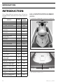
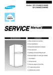
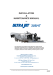
2003 Shop Manual GTI, GTI LE, GTI LE RFI, GTX DI, XP DI, RX DI, LRV DI, GTX 4-TEC SERIES Legal deposit: National Library of Quebec 2nd trimester 2003 National Library of Canada All rights reserved. No parts of this manual may be reproduced in any form without the prior written permission of Bombardier Inc. ©Bombardier Inc. 2003 Technical Publications Bombardier Inc. Valcourt (Quebec) Canada Printed in Canada ®*Registered trademarks of Bombardier Inc. Knight’s Spray-Nine† is a trademark of Korkay System Ltd GTX† is a trademark of Castrol Ltd. Used under license Loctite® is a trademark of Loctite Corporation Snap-on® is a trademark of Snap-on Tools Corporation Gelcote® is a trademark of Gelcote International Limited The following trademarks are the property of Bombardier Inc. or its subsidiaries: SEA-DOO® BOMBARDIER-ROTAX® BOMBARDIER LUBE® BOMBARDIER-ROTAX Formula XP-S Synthetic Injection Oil BOMBARDIER Formula XP-S DI Synthetic Injection Oil BOMBARDIER-ROTAX Injection Oil Sea-Doo Synthetic Grease Sea-Doo LKTM DESSTM Rotax® O.P.A.S.TM TOPSTM TABLE OF CONTENTS SECTION SUBSECTION PAGE SAFETY NOTICE .................................................................................................................................. III INTRODUCTION ................................................................................................................................... IV 01 SERVICE TOOLS AND PRODUCTS 01 - Table of contents ...................................................................... 02 - Mandatory service tools............................................................ 03 - Optional service tools................................................................ 04 - Service products ....................................................................... 01-01-1 01-02-1 01-03-1 01-04-1 02 MAINTENANCE 01 - Table of contents ...................................................................... 02 - Periodic inspection chart ........................................................... 03 - Flushing and lubrication............................................................. 04 - Water-flooded engine................................................................ 05 - Storage...................................................................................... 02-01-1 02-02-1 02-03-1 02-04-1 02-05-1 03 TROUBLESHOOTING 01 - Troubleshooting chart ............................................................... 03-01-1 04 ENGINE (2-stroke) 01 - Table of contents ...................................................................... 02 - Leak test ................................................................................... 03 - Removal and installation ........................................................... 04 - Magneto system ....................................................................... 05 - Top end ..................................................................................... 06 - Bottom end ............................................................................... 07 - Rotary valve............................................................................... 08 - Exhaust system......................................................................... 04-01-1 04-02-1 04-03-1 04-04-1 04-05-1 04-06-1 04-07-1 04-08-1 05 ENGINE (4-TEC) 01 - Table of contents ...................................................................... 02 - Leak test ................................................................................... 03 - Intake system............................................................................ 04 - Exhaust system......................................................................... 05 - Removal and installation ........................................................... 06 - PTO housing/magneto .............................................................. 07 - Lubrication system.................................................................... 08 - Cylinder head and valves........................................................... 09 - Engine block.............................................................................. 05-01-1 05-02-1 05-03-1 05-04-1 05-05-1 05-06-1 05-07-1 05-08-1 05-09-1 06 ENGINE MANAGEMENT (RFI) 01 - Table of contents ...................................................................... 02 - Overview................................................................................... 03 - Diagnostic procedures .............................................................. 04 - Component inspection .............................................................. 05 - Troubleshooting summary ........................................................ 06 - Adjustment................................................................................ 07 - Removal and installation ........................................................... 06-01-1 06-02-1 06-03-1 06-04-1 06-05-1 06-06-1 06-07-1 07 ENGINE MANAGEMENT (DI) 01 - Table of contents ...................................................................... 02 - Overview................................................................................... 03 - Component inspection and adjustment .................................... 04 - Diagnostic procedures .............................................................. 07-01-1 07-02-1 07-03-1 07-04-1 08 ENGINE MANAGEMENT (4-TEC) 01 - Table of contents ...................................................................... 02 - Overview................................................................................... 03 - Component inspection and adjustment .................................... 04 - Diagnostic procedures .............................................................. 08-01-1 08-02-1 08-03-1 08-04-1 09 COOLING SYSTEM 01 - Table of contents ...................................................................... 02 - Circuit, components and care ................................................... 09-01-1 09-02-1 SMR2003_001_00_00A2.FM I TABLE OF CONTENTS II PAGE SECTION SUBSECTION 10 FUEL SYSTEM 01 - Table of contents ...................................................................... 02 - Fuel circuit ................................................................................ 03 - Air intake (2-stroke)................................................................... 04 - Carburetor................................................................................. 10-01-1 10-02-1 10-03-1 10-04-1 11 LUBRICATION SYSTEM (2-stroke) 01 - Table of contents ...................................................................... 02 - Oil injection system .................................................................. 03 - Oil injection pump..................................................................... 11-01-1 11-02-1 11-03-1 12 ELECTRICAL SYSTEM 01 - Table of contents ...................................................................... 02 - Ignition system (carbureted engines) ....................................... 03 - Charging system....................................................................... 04 - Starting system......................................................................... 05 - Instruments and accessories.................................................... 06 - DESS (carbureted and RFI engines).......................................... 12-01-1 12-02-1 12-03-1 12-04-1 12-05-1 12-06-1 13 PROPULSION SYSTEM 01 - Table of contents ...................................................................... 02 - Jet pump................................................................................... 03 - Drive system............................................................................. 04 - Reverse system........................................................................ 05 - Variable trim system ................................................................. 13-01-1 13-02-1 13-03-1 13-04-1 13-05-1 14 STEERING SYSTEM 01 - Table of contents ...................................................................... 02 - Steering system........................................................................ 03 - Alignment ................................................................................. 14-01-1 14-02-1 14-03-1 15 SUSPENSION 01 - Table of contents ...................................................................... 02 - Direct action suspension .......................................................... 15-01-1 15-02-1 16 HULL/BODY 01 - Table of contents ...................................................................... 02 - Adjustment and repair .............................................................. 16-01-1 16-02-1 17 TECHNICAL DATA 01 - GTI and GTI LE models............................................................. 02 - GTI LE RFI models.................................................................... 03 - GTX DI, RX DI and XP DI models.............................................. 04 - LRV DI models.......................................................................... 05 - GTX 4-TEC models.................................................................... 17-01-1 17-02-1 17-03-1 17-04-1 17-05-1 18 WIRING DIAGRAMS 01 - Wiring diagrams........................................................................ 18-01-1 SMR2003_001_00_00A2.FM SAFETY NOTICE SAFETY NOTICE 0 This manual has been prepared as a guide to correctly service and repair all 2003 SEA-DOO watercraft. See model list below. This edition was primarily published to be used by watercraft mechanical technicians who are already familiar with all service procedures relating to Bombardier made watercraft. Mechanical technicians should attend training courses given by Bombardier Training Dept. Please note that the instructions will apply only if proper hand tools and special service tools are used. This Shop Manual uses technical terms which may be slightly different from the ones used in the Parts Catalog. It is understood that this manual may be translated into another language. In the event of any discrepancy, the English version shall prevail. The content depicts parts and/or procedures applicable to the particular product at time of writing. Service and Warranty Bulletins may be published to update the content of this manual. Make sure to read and understand these. In addition, the sole purpose of the illustrations throughout the manual, is to assist identification of the general configuration of the parts. They are not to be interpreted as technical drawings or exact replicas of the parts. The use of Bombardier parts is most strongly recommended when considering replacement of any component. Dealer and/or distributor assistance should be sought in case of doubt. The engines and the corresponding components identified in this document should not be utilized on product(s) other than those mentioned in this document. Torque wrench tightening specifications must be strictly adhered to. Locking devices (ex.: locking tab, self-locking fasteners, etc.) must be installed or replaced with new ones. If the efficiency of a locking device is impaired, it must be renewed. This manual emphasizes particular information denoted by the wording and symbols: WARNING Identifies an instruction which, if not followed, could cause serious personal injury including possibility of death. CAUTION: Denotes an instruction which, if not followed, could severely damage vehicle components. NOTE: Indicates supplementary information needed to fully complete an instruction. Although the mere reading of such information does not eliminate the hazard, your understanding of the information will promote its correct use. Always use common shop safety practice. Bombardier Inc. disclaims liability for all damages and/or injuries resulting from the improper use of the contents. We strongly recommend that any services be carried out and/or verified by a highly skilled professional mechanic. It is understood that certain modifications may render use of the vehicle illegal under existing federal, provincial and state regulations. SMR2003_001_00_00A2.FM III INTRODUCTION INTRODUCTION This Shop Manual covers the following BOMBARDIER made SEA-DOO® 2003 watercraft models. ENGINE TYPE MODEL NUMBER XP DI 947 DI 6131 XP DI International 947 DI 6130 GTI (blue) International 717 5568 GTI (ultraviolet) 717 5598 GTI California (ultraviolet) 717 5567 GTI International (ultraviolet) 717 5597 GTI LE (earthen clay) 717 6102 GTI LE International (earthen clay) 717 6101 GTI LE RFI 787 RFI 6104 GTI LE RFI International 787 RFI 6103 GTX DI 947 DI 6119 GTX DI International 947 DI 6118 RX DI 947 DI 6123 MODELS RX DI International 947 DI 6122 LRV DI 947 DI 5771 GTX 4-TEC 1503 6112 GTX 4-TEC International 1503 6111 GTX 4-TEC Vans Triple Crown Edition 1503 6126 GTX 4-TEC Vans Triple Crown Edition International 1503 6125 GTX 4-TEC Supercharged (viper red) 1503 6129 GTX 4-TEC Supercharged International (viper red) 1503 6128 GTX 4-TEC Supercharged (yellow) 1503 6106 GTX 4-TEC Supercharged International (yellow) 1503 6105 GTX 4-TEC Supercharged Limited 1503 6108 GTX 4-TEC Supercharged Limited International 1503 6107 IV 0 HULL IDENTIFICATION NUMBER (H.I.N.) It is located on footboard at the rear of watercraft. 1 F00L2EA 1. Hull Identification Number (H.I.N.) F08L0QA 1 TYPICAL 1. Hull Identification Number (H.I.N.) SMR2003_001_00_00A2.FM INTRODUCTION All Models The Hull Identification Number is composed of 12 digits: ZZN12345L495 Serial number* F00A0CB Manufacturer Model year Year of production Month of production *A letter may also be used as a digit. ENGINE IDENTIFICATION NUMBER (E.I.N.) F01D87A 717 Engines The Engine Identification Number is located on the upper side of the magneto housing. 1 1. Engine Identification Number (E.I.N.) 947 DI Engines The Engine Identification Number is located on the upper crankcase on MAGNETO side. 1 F01D01A TYPICAL 1. Engine Identification Number (E.I.N.) 787 RFI Engines The Engine Identification Number is located on the upper crankcase on PTO side. F06D15A 1 1. Engine Identification Number (E.I.N.) ARRANGEMENT OF THIS MANUAL The manual is divided into many major sections as you can see in the main table of contents at the beginning of the manual. Several sections are divided in various subsections. There is a table of contents at the beginning of many sections. SMR2003_001_00_00A2.FM V INTRODUCTION TYPICAL PAGE Page heading indicates section and subsection detailed. Subsection title indicates beginning of the subsection. Subsection 04 (MAGNETO SYSTEM) Italic sub-title above exploded view indicate pertaining models. Drop represents a liquid product to be applied to a surface. In this case Loctite 243 to screw threads. Loctite 243 Loctite 243 Dotted box contains parts of a particular model or an exploded view. Loctite 243 Exploded view assits you in identifying parts and related positions. Loctite 243 Loctite 243 Bold face number indicates special procedure concerning this part. Loctite 648 145 Nm (107 lbfft) Anti-seize lubricant F01D4WS Illustration number for publishing process. 03-04-1 Page numbering system: 03: ENGINE section 04: MAGNETO SYSTEM subsection 1: First page of this subsection F01A0CS VI SMR2003_001_00_00A2.FM INTRODUCTION TYPICAL PAGE Sub-title with part name(s) from exploded view. Section 06 FUEL SYSTEM Subsection 03 (CARBURETORS) Title indicates main procedure to be carried-out. Service tool to be used to perform a certain procedure. Title in italic indicates a particular procedure concerning a model. Sub-sub-title in this case indicates that particular procedure for XP is finished, so from this point, all others models are concerned. CARBURETOR REMOVAL DISASSEMBLY AND INSPECTION To remove carburetors from engine, proceed as follows: Remove air vent tube support. Unlock retaining slides holding air intake silencer base. Remove air intake silencer base from watercraft. Remove screws holding flame arrester base support to cylinder head cover. Unscrew base retaining screws then remove base from carburetors and move to front of watercraft. Turn the valve to OFF position. Inspect parts for corrosion dammage (shaft, butterfly, spring screw, check valve housing, etc.). Diaphragm PUMP DIAPHRAGM LEAK TEST Using a suitable pump gauge tester, perform the following test proceeding as follows: - Install pump gauge tester (P/N 295 000 083) on pulse nipple. - Pump tester until it reaches 28 kPa (4 PSI). NOTE: For fuel line removal, use pliers (P/N 295 000 054). 1 A Disconnect pulse line from fuel pump. Disconnect fuel fuel supply line from fuel pump. Disconnect fuel return line. Disconnect oil injection pump cable, throttle cable and choke cable. Illustration always follows text it is pertained to. XP Model Only Remove screws no. 6 and lock washers no. 7 retaining carburetors. All Others Models Remove 4 bolts no. 8 and lock washers no. 12 from rotary valve cover then move carburetors and rotary valve cover on top of engine. NOTE: When removing rotary valve cover , pay attention that the rotary valve stay in place, other-wise it must be timed. Remove carburetors from intake manifold. Disconnect fuel bypass line between carburetors (twin carburetors). Remove carburetor(s) from rotary valve cover. Sub-sub-title in capital indicates a particular testing, adjustment or repair procedure. F01F0XB 2 1 TYPICAL mention indicates a general view which does not represent full detail. 2 TYPICAL 1 2 Diaphragm must stand pressure for 10 seconds. If pressure drops, replace diaphragm. Numbers in a frame are used to give a sequence to be perfomed. Letters are used for any measures. 06-03-4 Bold numbers in the text refer to the parts shown in the exploded view at the beginning of the subsection. Numbers are used for description of components. F01A0BS SMR2003_001_00_00A2.FM VII INTRODUCTION LIST OF ABBREVIATIONS USED IN THIS MANUAL ADC AC APS ATS B.U.D.S. CDI CPS CSI DC DESS DI E.I.N. ECM ECU EPA HP LED MAG MPEM MPH MPI N.A. OPT P/N PFD PSI PTO RAVE RFI RPM STD TBD TDC TPS VDC VCK VDC VTS WTS VIII DESCRIPTION Analog to Digital Conversion Alternate Current Air Pressure Sensor Air Temperature Sensor Bombardier Utility and Diagnostic Software Capacitor Discharge Ignition Crankshaft Position Sensor Cooling System Indicator Direct Current Digitally Encoded Security System Direct Injection Engine Identification Number Engine Control Module Electronic Control Unit Environmental Protection Agency (USA) Horse Power Light Emitting Diode Magneto Multi-Purpose Electronic Module Mile Per Hour Multi Protocol Interface Not Applicable Optional Part Number Personal Flotation Device Pound Per Square Inch Power Take Off Rotax Adjustable Variable Exhaust Rotax Fuel Injection Revolution Per Minute Standard To Be Determined Top Dead Center Throttle Position Sensor Volt Direct Current Vehicle Communication Kit Volt Direct Current Variable Trim System Water Temperature Sensor GENERAL INFORMATION The use of RIGHT (starboard) and LEFT (port) indications in the text, always refers to driving position (when sitting on watercraft). Besides, in the marine industry, FRONT is called BOW and REAR is called STERN. 1 2 F01L45B 1. Left (port) 2. Right (starboard) The information and component/system descriptions contained in this manual are correct at time of writing. Bombardier Inc. however, maintains a policy of continuous improvement of its products without imposing upon itself any obligation to install them on products previously manufactured. Bombardier Inc. reserves the right at any time to discontinue or change specifications, designs, features, models or equipment without incurring obligation. This Shop Manual uses technical terms which may be different from the ones of the Parts Catalogs. When ordering parts always refer to the specific model Parts Catalogs. ILLUSTRATIONS AND PROCEDURES The illustrations show the typical construction of the different assemblies and, in all cases, may not reproduce the full detail or exact shape of the parts shown, however, they represent parts which have the same or a similar function. CAUTION: These watercraft are designed with parts dimensioned mostly in the metric system. However some components may be from the imperial system. When replacing fasteners, make sure to use only those recommended by Bombardier. SMR2003_001_00_00A2.FM INTRODUCTION As many of the procedures in this manual are interrelated, we suggest, that before undertaking any task, you read and thoroughly understand the entire section or subsection in which the procedure is contained. A number of procedures throughout the book require the use of special tools. Before undertaking any procedure, be sure that you have on hand all the tools required, or approved equivalents. ENGINE EMISSIONS INFORMATION Manufacturer’s Responsibility Beginning with 1999 model year engines, PWC manufacturers of marine engines must determine the exhaust emission levels for each engine horsepower family and certify these engines with the United States of America Environmental Protection Agency (EPA). An emissions control information label, showing emission levels and engine specifications, must be placed on each vehicle at the time of manufacture. Dealer Responsibility When performing service on all 1999 and more recent Sea-Doo watercrafts that carry an emissions control information label, adjustments must be kept within published factory specifications. Replacement or repair of any emission related component must be executed in a manner that maintains emission levels within the prescribed certification standards. Dealers are not to modify the engine in any manner that would alter the horsepower or allow emission levels to exceed their predetermined factory specifications. Exceptions include manufacturer’s prescribed changes, such as altitude adjustments for example. Owner Responsibility The owner/operator is required to have engine maintenance performed to maintain emission levels within prescribed certification standards. The owner/operator is not to, and should not allow anyone to modify the engine in any manner that would alter the horsepower or allow emissions levels to exceed their predetermined factory specifications. SMR2003_001_00_00A2.FM EPA Emission Regulations All new 1999 and more recent Sea-Doo watercrafts manufactured by Bombardier are certified to the EPA as conforming to the requirements of the regulations for the control of air pollution from new watercraft engines. This certification is contingent on certain adjustments being set to factory standards. For this reason, the factory procedure for servicing the product must be strictly followed and, whenever practicable, returned to the original intent of the design. The responsibilities listed above are general and in no way a complete listing of the rules and regulations pertaining to the EPA requirements on exhaust emissions for marine products. For more detailed information on this subject, you may contact the following locations: VIA U.S. POSTAL SERVICE: Office of Mobile Sources Engine Programs and Compliance Division Engine Compliance Programs Group (6403J) 401 M St. NW Washington, DC 20460 VIA EXPRESS or COURIER MAIL: Office of Mobile Sources Engine Programs and Compliance Division Engine Compliance Programs Group (6403J) 501 3rd St. NW Washington, DC 20001 EPA INTERNET WEB SITE: http:/www.epa.gov/omswww SELF-LOCKING FASTENERS PROCEDURE The following describes the most common application procedures when working with self-locking fasteners. Use a metal brush or a screwtap to clean the hole properly then use a solvent (Methyl-Chloride), let act during 30 minutes and wipe off. The solvent utilization is to ensure the adhesive works properly. IX INTRODUCTION LOCTITE APPLICATION PROCEDURE Blind Holes The following describes the most common application procedures when working with Loctite products. NOTE: Always use proper strength Loctite product as recommended in this Shop Manual. 1 2 THREADLOCKER Uncovered Holes (bolts and nuts) A00A3MA 1. On threads 2. On threads and at the bottom of hole 1 2 A00A3LA 1. Apply here 2. Do not apply 1. Clean threads (bolt and nut) with solvent. 2. Apply Loctite Primer N (P/N 293 800 041) on threads and allow to dry. 3. Choose proper strength Loctite threadlocker. 4. Fit bolt in the hole. 5. Apply a few drops of threadlocker at proposed tightened nut engagement area. 6. Position nut and tighten as required. 1. Clean threads (bolt and hole) with solvent. 2. Apply Loctite Primer N (P/N 293 800 041) on threads (bolt and nut) and allow to dry for 30 seconds. 3. Choose proper strength Loctite threadlocker. 4. Apply several drops along the threaded hole and at the bottom of the hole. 5. Apply several drops on bolt threads. 6. Tighten as required. Stud in Blind Holes 1 3 2 A00A5RA 1. On threads 2. On threads and in the hole 3. Onto nut threads X SMR2003_001_00_00A2.FM INTRODUCTION 1. Clean threads (stud and hole) with solvent. 2. Apply Loctite Primer N (P/N 293 800 041) on threads and allow to dry. 3. Put several drops of proper strength Loctite threadlocker on female threads and in hole. 4. Apply several drops of proper strength Loctite on stud threads. 5. Install stud. 6. Install cover, etc. 7. Apply drops of proper strength Loctite on uncovered threads. 8. Tighten nuts as required. Adjusting Screw 2 1 A00A3PA Preassembled Parts 1. Apply here 2. Plunger 1 1. Adjust screw to proper setting. 2. Apply drops of proper strength Loctite threadlocker on screw/body contact surfaces. 3. Avoid touching metal with tip of flask. NOTE: If it is difficult to readjust, heat screw with a soldering iron (232°C (450°F)). STRIPPED THREAD REPAIR Stripped Threads 2 5 A00A3OA 1 1. Apply here 2. Do not apply 1. Clean bolts and nuts with solvent. 2. Assemble components. 3. Tighten nuts. 4. Apply drops of proper strength Loctite on bolt/nut contact surfaces. 5. Avoid touching metal with tip of flask. NOTE: For preventive maintenance on existing equipment, retighten nuts and apply proper strength Loctite on bolt/nut contact surfaces. SMR2003_001_00_00A2.FM 6 8 2 3 A00A3QA 1. 2. 3. 4. 5. 6. 7. 8. 4 7 Release agent Stripped threads Form-A-Thread Tape Cleaned bolt Plate New threads Threadlocker XI INTRODUCTION Standard Thread Repair 1. Follow instructions on Loctite FORM-A-THREAD 81668 package. 2. If a plate is used to align bolt: a. Apply release agent on mating surfaces. b. Put waxed paper or similar film on the surfaces. 3. Twist bolt when inserting it to improve thread conformation. NOTE: NOT intended for engine stud repairs. Repair of Small Holes/Fine Threads Option 1: Enlarge damaged hole, then follow Standard Thread Repair procedure. Option 2: Apply FORM-A-THREAD on the screw and insert in damaged hole. Permanent Stud Installation (light duty) 1. Use a stud or thread on desired length. 2. DO NOT apply release agent on stud. 3. Do a Standard Thread Repair. 4. Allow to cure for 30 minutes. 5. Assemble. NOTE: Avoid grinding. 2. Clean both mating surfaces with solvent. 3. Spray Loctite Primer N on both mating surfaces and on both sides of gasket. Allow to dry 1 or 2 minutes. 4. Apply GASKET ELIMINATOR 518 (P/N 293 800 038) on both sides of gasket, using a clean applicator. 5. Place gasket on mating surfaces and assemble immediately. NOTE: If the cover is bolted to blind holes (above), apply proper strength Loctite in the hole and on threads. Tighten. If holes are sunken, apply proper strength Loctite on bolt threads. 6. Tighten as usual. MOUNTING ON SHAFT Mounting with a Press GASKET COMPOUND All Parts 1 1 2 2 3 A00A3UA 1 A00A3SA 1 3 1. Proper strength Loctite 2. Loctite Primer N (P/N 293 800 041) and Gasket Eliminator 518 (P/N 293 800 038) on both sides of gasket 3. Loctite Primer N only 1. Remove old gasket and other contaminants with Loctite Chisel remover (P/N 413 708 500). Use a mechanical mean if necessary. XII 1. Bearing 2. Proper strength Loctite 3. Shaft Standard 1. Clean shaft external part and element internal part. 2. Apply a strip of proper strength Loctite on shaft circumference at insert or engagement point. NOTE: Retaining compound is always forced out when applied on shaft. 3. DO NOT use anti-seize Loctite or any similar product. 4. No curing period is required. SMR2003_001_00_00A2.FM INTRODUCTION Mounting in Tandem 1. Apply retaining compound on internal element bore. 2. Continue to assemble as shown above. CASE-IN COMPONENTS Metallic Gaskets A00A3VA 1 1. Proper strength Loctite 1. Clean inner housing diameter and outer gasket diameter. 2. Spray housing and gasket with Loctite Primer N (P/N 293 800 041). 3. Apply a strip of proper strength Loctite on leading edge of outer metallic gasket diameter. NOTE: Any Loctite product can be used here. A low strength liquid is recommended as normal strength and gap are required. 4. Install according to standard procedure. 5. Wipe off surplus. 6. Allow it to cure for 30 minutes. NOTE: Normally used on worn-out housings to prevent leaking or sliding. It is generally not necessary to remove gasket compound applied on outer gasket diameter. SMR2003_001_00_00A2.FM TIGHTENING TORQUES Tighten fasteners to torque mentioned in exploded views and text. When they are not specified refer to following table.The table also gives the metric conversion. N•m 1 2 3 4 5 6 7 8 9 10 11 12 13 14 15 16 17 18 19 FASTENER SIZE (8.8) N•m 20 21 22 23 24 25 26 27 28 29 30 31 32 33 34 35 36 37 FASTENER SIZE (8.8) M4 M5 M6 M8 Lbf•in 9 18 27 35 44 53 62 71 80 89 97 106 115 124 133 142 150 159 168 Lbf•ft 15 15 16 17 18 18 19 20 21 21 22 23 24 24 25 26 27 27 XIII INTRODUCTION N•m 38 39 40 41 42 43 44 45 46 47 48 49 50 51 52 53 54 55 56 57 58 59 60 61 62 63 64 65 66 67 68 69 70 71 72 73 74 75 76 77 78 79 80 81 82 XIV FASTENER SIZE (8.8) M10 M12 Lbf•ft 28 29 30 30 31 32 32 33 34 35 35 36 37 38 38 39 40 41 41 42 43 44 44 45 46 46 47 48 49 49 50 51 52 52 53 54 55 55 56 57 58 58 59 60 60 N•m 83 84 85 86 87 88 89 90 91 92 93 94 95 96 97 98 99 100 101 102 103 104 105 106 107 108 109 110 111 112 113 114 115 116 117 118 119 120 121 122 123 124 125 126 127 FASTENER SIZE (8.8) Lbf•ft 61 62 63 63 64 65 66 66 67 68 69 69 70 71 72 72 73 74 74 75 76 77 77 78 79 80 80 81 82 83 83 84 85 86 86 87 88 89 89 90 91 91 92 93 94 SMR2003_001_00_00A2.FM INTRODUCTION N•m 128 129 130 131 132 133 134 135 136 137 138 139 140 141 142 143 144 145 146 147 148 149 150 FASTENER SIZE (8.8) M14 Lbf•ft 94 95 96 97 97 98 99 100 100 101 102 103 103 104 105 105 106 107 108 108 109 110 111 TIGHTENING TORQUES FOR 8.8 GRADE BOLTS AND NUTS Technical Publications Bombardier Inc. Valcourt (Quebec), Canada SMR2003_001_00_00A2.FM XV