1
Operation Manual
© ZOOM Corporation
Reproduction of this manual, in whole or in part,
by any means, is prohibited.
SAFETY PRECAUTIONS / Usage Precautions
Handling
SAFETY PRECAUTIONS
Warning
In this manual, symbols are used to highlight warnings and
cautions for you to read so that accidents can be prevented. The
meanings of these symbols are as follows:
This symbol indicates explanations about extremely
dangerous matters. If users ignore this symbol and
Warning handle the device the wrong way, serious injury or
death could result.
This symbol indicates explanations about dangerous
matters. If users ignore this symbol and handle the
device the wrong way, bodily injury and damage to
the equipment could result.
Caution
Caution
Please observe the following safety tips and precautions to
ensure hazard-free use of the B2.1u.
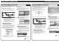
Power requirements
Warning
Since power consumption of this unit is fairly high, we
recommend the use of an AC adapter whenever
possible. When powering the unit from batteries, use
only alkaline types.
[AC adapter operation]
• Be sure to use only an AC adapter which supplies 9 V DC,
300 mA and is equipped with a "center minus" plug
(Zoom AD-0006). The use of an adapter other than the
specified type may damage the unit and pose a safety
hazard.
• Connect the AC adapter only to an AC outlet that supplies
the rated voltage required by the adapter.
• When disconnecting the AC adapter from the AC outlet,
always grasp the adapter itself and do not pull at the cable.
• During lightning or when not using the unit for an
extended period, disconnect the AC adapter from the AC
outlet.
[Battery operation]
• Use four conventional IEC R6 (size AA) batteries
(alkaline).
• The B2.1u cannot be used for recharging.
• Pay close attention to the labelling of the battery to make
sure you choose the correct type.
• When not using the unit for an extended period, remove
the batteries from the unit.
• If battery leakage has occurred, wipe the battery
compartment and the battery terminals carefully to
remove all remnants of battery fluid.
• While using the unit, the battery compartment cover
should be closed.
Environment
Warning
To prevent the risk of fire, electric shock or
malfunction, avoid using your B2.1u in environments
where it will be exposed to:
•
•
•
•
•
2
Extreme temperatures
Heat sources such as radiators or stoves
High humidity or moisture
Excessive dust or sand
Excessive vibration or shock
• Never place objects filled with liquids, such as vases, on
the B2.1u since this can cause electric shock.
• Do not place naked flame sources, such as lighted candles,
on the B2.1u since this can cause fire.
• The B2.1u is a precision instrument. Do not exert undue
pressure on the keys and other controls. Also take care not
to drop the unit, and do not subject it to shock or excessive
pressure.
• Take care that no foreign objects (coins or pins etc.) or
liquids can enter the unit.
Connecting cables and input and output
jacks
You should always turn off the power to the B2.1u and
all other equipment before connecting or disconnecting
any cables. Also make sure to disconnect all connection
cables and the power cord before moving the B2.1u.
Alterations
Warning
Never open the case of the B2.1u or attempt to modify
the product in any way since this can result in damage
to the unit.
Volume
Caution
Do not use the B2.1u at a loud volume for a long time
since this can cause hearing impairment.
Usage Precautions
Electrical interference
For safety considerations, the B2.1u has been designed to
provide maximum protection against the emission of
electromagnetic radiation from inside the device, and protection
from external interference. However, equipment that is very
susceptible to interference or that emits powerful
electromagnetic waves should not be placed near the B2.1u, as
the possibility of interference cannot be ruled out entirely.
With any type of digital control device, the B2.1u included,
electromagnetic interference can cause malfunctioning and can
corrupt or destroy data. Care should be taken to minimize the
risk of damage.
Cleaning
Use a soft, dry cloth to clean the B2.1u. If necessary, slightly
moisten the cloth. Do not use abrasive cleanser, wax, or solvents
(such as paint thinner or cleaning alcohol), since these may dull
the finish or damage the surface.
Please keep this manual in a convenient place for
future reference.
* Windows and Windows XP are registered trademarks of
Microsoft Corporation.
* Macintosh is a registered trademark of Apple Computer.
* All other product names, trademarks, and company names
mentioned in this manual are the property of their respective
owners.
ZOOM B2.1u
Contents
SAFETY PRECAUTIONS / Usage Precautions ................................ 2
SAFETY PRECAUTIONS .................................................................... 2
Usage Precautions .............................................................................. 2
Features .............................................................................................. 4
Terms Used in This Manual .............................................................. 5
Controls and Functions / Connections ........................................... 6
Selecting a Patch ............................................................................... 8
Using the Tuner ............................................................................... 10
Using the Rhythm Function ............................................................ 12
Editing a Patch ................................................................................. 14
Storing/Copying Patches ............................................................... 16
Using the Built-in Expression Pedal ............................................... 18
Other Functions................................................................................ 20
Making settings for the internal expression pedal .......................... 20
Adjusting the sensitivity of the built-in expression pedal ............... 20
Using an external expression pedal (FP01/FP02)............................ 21
Using a foot switch (FS01) ................................................................ 21
Using the B2.1u as audio interface for a computer......................... 22
Use as a direct box ........................................................................... 23
Restoring Factory Defaults ............................................................ 24
Linking Effects.................................................................................. 25
Effect Types and Parameters.......................................................... 26
How to read the parameter table ..................................................... 26
COMP/LIMIT ................................................................................. 27
WAH/EFX ...................................................................................... 27
DRIVE/SYNTH ............................................................................... 29
ZNR/MIX ....................................................................................... 30
LO EQ ........................................................................................... 30
HI EQ............................................................................................. 31
MOD/SFX ...................................................................................... 31
DELAY ........................................................................................... 33
REVERB ........................................................................................ 33
CONTROL..................................................................................... 34
Specifications .................................................................................. 35
Troubleshooting .............................................................................. 35
B2.1u Preset Pattern ............................................................ Back cover
The FCC regulation warning (for U.S.A.)
This equipment has been tested and found to comply with the limits for a Class B digital device, pursuant to Part
15 of the FCC Rules. These limits are designed to provide reasonable protection against harmful interference in a
residential installation. This equipment generates, uses, and can radiate radio frequency energy and, if not
installed and used in accordance with the instructions, may cause harmful interference to radio communications.
However, there is no guarantee that interference will not occur in a particular installation. If this equipment does
cause harmful interference to radio or television reception, which can be determined by turning the equipment
off and on, the user is encouraged to try to correct the interference by one or more of the following measures:
• Reorient or relocate the receiving antenna.
• Increase the separation between the equipment and receiver.
• Connect the equipment into an outlet on a circuit different from that to which the receiver is
connected.
• Consult the dealer or an experienced radio/TV technician for help.
ZOOM B2.1u
3
Features
Thank you for selecting the ZOOM B2.1u (hereafter simply called the "B2.1u"). The B2.1u is a multi
effect processor with the following features and functions.
● Latest technology for outstanding performance
96 kHz / 24 bit sampling (with 32 bit internal processing) assures excellent sound quality. The B2.1u
carves out a sonic outline in superb detail while preserving the original sound character of the bass guitar.
The B2.1u also has a USB connection and can be used as a direct bass guitar/computer interface.
● Versatile palette of effects
Out of a total of 47 effects, up to nine (including ZNR) can be used simultaneously. The dazzling choices
provided by the B2.1u include distortion effects modeled on famous amps and compact effects, compressor/
limiter effects for dynamic punch, a parametric equalizer essential for working on sonic nuances, as well as
various delay and modulation effects. Both in quality and versatility, the B2.1u far surpasses anything in its
class. You can even transform the output into a cool synth bass or fretless bass sound.
● Really usable patches straight out of the box
Effect module combinations are stored and called up in units referred to as patches. The B2.1u comes
with a full complement of 40 read-only plus 40 user-programmable patches, giving you 80 great reasons
to start grooving.
● Great for live performances and direct recording
The distortion effects have a special parameter that selects whether to apply only the head amp
characteristics or add also the cabinet sound. This lets you use the B2.1u effectively not only for a live
performance but also when feeding the signal directly to a recorder.
● XLR connector for direct output
In addition to the [OUTPUT/PHONES] jack, the B2.1u features an XLR connector for sending a
balanced line-level signal to equipment such as a PA mixer or recording console. The signal can be
derived from a point before or after effect processing. A ground lift switch is also provided, which is
useful to prevent hum in the direct output caused by ground loops.
● Integrated auto-chromatic tuner and rhythm functions
Realistic PCM sound sources are available to auto-play a number of rhythm patterns. This is convenient
for use as a metronome during practice or to provide a simple rhythm part for a quick session. An autochromatic tuner for bass guitar is also built right into the unit, including a function for silent tuning
which lets you easily tune your instrument on stage.
● Sophisticated user interface
The combination of a rotary type selector and three parameter knobs make the effect editing process
intuitive and quick. The mute interval when switching patches has been reduced to less than 8
milliseconds. Seamless patch changing is now a reality.
● Dual power supply principle allows use anywhere
The B2.1u can be powered from four IEC R6 (size AA) batteries or an AC adapter. Continuous
operating time on batteries is approximately 6 hours with alkaline batteries.
● Easy operation with expression pedal and foot switch
An optional foot switch (FS01) or expression pedal (FP01/FP02) can be connected to the [CONTROL
IN] jack. The foot switch is convenient for quickly toggling effect programs, setting the tempo of the
rhythm function, turning delay hold on and off, etc. A connected expression pedal lets you adjust the
volume in real time.
Please take the time to read this manual carefully so as to get the most out of the unit and to ensure
optimum performance and reliability.
4
ZOOM B2.1u
Terms Used in This Manual
This section explains some important terms that are used throughout the B2.1u documentation.
IN
COMP/LIMIT WAH/EFX DRIVE/SYNTH ZNR/MIX LO EQ HI EQ
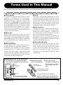
■ Effect module
As shown in the illustration above, the B2.1u can be
thought of as a combination of several single effects.
Each of these effects is referred to as an effect module.
In addition to modules comprising compressor and
limiter effects (COMP/LIMIT), amp simulator/synth
bass effects (DRIVE/SYNTH), and modulation/special
effects (MOD/SFX), the B2.1u also provides a module
for ZNR (ZOOM Noise Reduction). Various
parameters such as effect intensity can be adjusted for
each module individually, and modules can be
switched on and off as desired.
■ Effect type
Within some effect modules, there are several
different effects which are referred to as effect types.
For example, the modulation/SFX effect module
(MOD/SFX) comprises chorus, flanger, pitch shifter,
delay, and other effect types. Only one of these can
be selected at a time.
■ Effect parameter
All effect modules have various parameters that can
be adjusted. These are called effect parameters.
In the B2.1u, effect parameters are adjusted with the
parameter knobs 1 – 3. Similar to the knobs on a
compact effect, these change aspects such as tonal
character and effect intensity. Which parameter is
assigned to each knob depends on the currently
selected effect module and effect type.
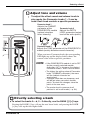
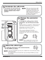
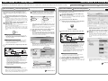
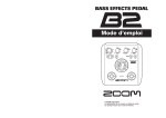
Operating the B2.1u on batteries
1. Turn the B2.1u over and open the cover
of the battery compartment on the bottom.
B2.1u
bottom view
Latch
MOD/SFX DELAY REVERB OUT
■ Patch
In the B2.1u, effect module combinations are stored
and called up in units referred to as patches. A patch
comprises information about the on/off status of each
effect module, about the effect type used in each
module, and about effect parameter settings. The
internal memory of the B2.1u holds up to 80 patches
(including 40 patches which allow read/write).
■ Bank and area
A group of ten patches is called a bank. The memory
of the B2.1u comprises a total of eight banks,
labelled A to d and 0 to 3. Banks A – d form the user
area which allows read/write. Banks 0 to 3 are the
preset area containing read-only patches.
The patches within each bank are numbered 0
through 9. To specify a patch of the B2.1u, you use
the format "A1" (patch number 1 from bank A), "06"
(patch number 6 from bank 0), etc.
■ Play mode/edit mode
The internal status of the B2.1u is referred to as the
operation mode. The two major modes are "play
mode" in which you can select patches and use them
for playing your instrument, and "edit mode" in
which you can modify the effects. The module
selector serves for switching between the play mode
and edit mode.
2. Insert four fresh IEC
R6 (size AA) batteries.
Four IEC R6
(size AA) batteries
3. Close the cover of
the battery compartment.
Push the cover in until the
latch audibly snaps into
place.
Insert batteries facing
in alternate directions.
Latch
Cover
ZOOM B2.1u
Press the latch to release
it and then raise the cover.
Use four IEC R6 (size AA) batteries.
When the batteries are getting low, the
indication "bt" appears on the display.
5
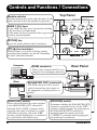
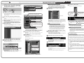
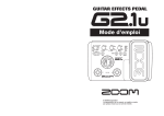
Controls and Functions / Connections
Top Panel
Module selector
Switches between play mode and edit mode. In edit
mode, the knob selects the module for operation.
BANK [-]/[+] keys
In play mode, the keys serve for directly switching
to the next lower or higher bank.
In edit mode, the keys switch the effect type for the
currently selected module.
[STORE] key
Serves for storing edited patches in memory.
[W]/[Q] foot switches
These switches are used for selecting patches,
switching effect modules on and off, controlling
the tuner, and other functions.
Computer
[USB] connector
Rear Panel
Allows you to connect the B2.1u. to a
computer, for exchanging audio data.
Mixer
[BALANCED OUT] connector
This XLR connector can be used to
send a balanced line-level signal to
PA equipment, recording devices, or
similar.
[PRE/POST] switch
[GROUND] switch
Selects the point where the signal supplied
at the [BALANCED OUT] connector is
obtained. In the "POST" position (switch
engaged), the signal is branched at a point
after effect processing, and in the "PRE"
position (switch disengaged), it is branched
at a point before effect processing.
Determines whether the [BALANCED OUT]
connector is grounded or not. In the "LIFT"
position (switch engaged), the ground pin of
the [BALANCED OUT] connector is
uncoupled from the signal path. In the
"CONNECT" position (switch disengaged),
the ground pin is connected.
6
ZOOM B2.1u
Controls and Functions / Connections
Parameter knobs 1 - 3
These knobs allow changing the level of effect parameters or of
the overall patch. During rhythm playback, the knobs let you select
a pattern, set the tempo, and adjust the rhythm volume.
[PEDAL ASSIGN] key
This key lets you select the function of the built-in expression
pedal. The currently selected function is shown by a lit LED.
[TAP] key
Allows manual input of time related effect parameter values such
as delay time, and rhythm pattern tempo.
RHYTHM [R/P] key
Serves to start/stop rhythm playback.
Display
Shows patch numbers, setting values, and other information about
operating the B2.1u.
Expression pedal
Lets you adjust the volume or various effect parameters in real
time during play.
[INPUT] jack
Bass Guitar
Serves for connecting the bass guitar.
[DC IN] jack
An AC adapter (ZOOM AD-0006)
with a rated output of 9 volts DC,
300 mA (center minus plug) can
be plugged into this jack.
AC adapter
[POWER] switch
Turns the unit on and off.
FP01/FP02
FS01
Headphones
Bass Guitar amplifiers
ZOOM B2.1u
[CONTROL IN] jack
Serves for connection of the optional foot switch
(FS01) or expression pedal (FP01/FP02).
[OUTPUT/PHONES] jack
This stereo phone jack serves for connection to the bass
guitar amplifier or for monitoring with headphones. It is
also possible to use a Y cable for sending the output to
two amplifiers, to produce a spacious stereo effect sound.
7
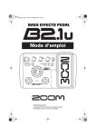
Selecting a Patch
To try out the various effects of the B2.1u, we recommend that you simply play your instrument while
switching patches.
Turn power on
Use a shielded cable with mono phone plug
to connect the bass guitar to the [INPUT]
jack of the B2.1u.
When using the B2.1u with the AC
adapter, plug the adapter into the outlet
and plug the cable from the adapter into
the [DC IN] jack on the B2.1u.
Set the [POWER] switch on the rear
panel of the B2.1u to ON.
Turn the bass guitar amplifier on and
adjust the volume to a suitable position.
Set the B2.1u to play mode
If the Module selector is set to a position
other than "PLAY", set it to "PLAY".
The bank and patch
that were selected
when the power was
last turned off will
appear on the display.
HINT
A1
Bank name
Patch number
Immediately after turning the B2.1u on,
the unit will be in play mode, even if the
Module selector is set to a position other
than "PLAY".
Select a patch
To switch the patch, press one of the [W]/[Q] foot switches.
Pressing the [W] foot switch calls up the next lower patch, and pressing the [Q] foot
switch calls up the next higher patch.
Repeatedly pressing one foot switch cycles through patches in the order A0 – A9 ... d0 – d9
→ 00 – 09 ... 30 – 39 → A0, or the reverse order.
8
ZOOM B2.1u
Selecting a Patch
Adjust tone and volume
To adjust the effect sound and volume levels in
play mode, the Parameter knobs 1 – 3 can be
used. Each knob controls a specific parameter.
Parameter knob 1
Adjusts the CABINET
parameter of the
DRIVE/SYNTH module
(cabinet simulator
effect intensity).
Parameter knob 3
Adjusts the PATCH
LEVEL parameter (output
level of the entire patch).
Parameter knob 2
Adjusts the TONE parameter of the DRIVE/SYNTH
module (mainly distortion sound character).
When you turn a Parameter knob, the corresponding
LED lights up and the display briefly shows the
current value of the respective parameter.
NOTE
• If the DRIVE/SYNTH module is set to OFF
for the currently selected module
(indication "oF" is shown on the display),
Parameter knobs 1 and 2 have no effect.
• The higher the setting value of Parameter
knob 1 (CABINET parameter), the more
will the cabinet character be
emphasized.
• Changes made here are temporary and
will be lost when you select another
patch. To retain the changes, store the
patch in the user area.
• The master level in common to all
patches is set in edit mode (→ p. 34).
Directly selecting a bank
To select the banks A – d, 0 – 3 directly, use the BANK [-]/[+] keys.
Pressing the BANK [-] key calls up the next lower bank, and pressing the BANK
[+] key calls up the next higher bank.
ZOOM B2.1u
9
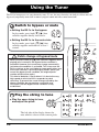
Using the Tuner
The B2.1u incorporates an auto-chromatic tuner. To use the tuner function, the built-in effects must be
bypassed (temporarily turned off) or muted (original sound and effect sound turned off).
Switch to bypass or mute
Setting the B2.1u to the bypass
In play mode, press both [W]/[Q] foot
switches together briefly and release.
BP
Setting the B2.1u to the mute state
In play mode, press both [W]/[Q] foot
switches together and hold for at least 1
second.
MT
Patch change at bypass/mute
When you press both [W]/[Q] foot switches together while
playing your instrument, the bypass/mute condition is
activated. However, the sound may change momentarily
just before the condition is activated. This is because the
B2.1u switches to the next higher or lower patch when one
of the foot switches is pressed slightly earlier. (When you
cancel the bypass/mute condition, the original patch
number will be active again.)
This kind of behavior is not a defect. It is due to the very
high speed at which the B2.1u responds to patch
switching. To prevent the sound change caused by the
above condition, do not produce sound with your
instrument until the bypass/mute condition is fully
established.
Play the string to tune
Play the open string to tune,
and adjust the pitch.
A8
The left side of the display shows the
note which is closest to the current pitch.
10
ZOOM B2.1u
Using the Tuner
Adjusting the reference pitch of the tuner
If required, you can fine-adjust the reference pitch of the B2.1u tuner.
The default setting after power-on is center A = 440 Hz.
Turn Parameter knob 1.
The current reference pitch is shown.
The adjustment range is 35 – 45 (center A = 435 to 445 Hz).
While the reference pitch value is shown, turn
Parameter knob 1 to adjust it.
40
42
When you release the Parameter knob, the
display indication will return to the
previous condition after a while.
NOTE
When you turn the B2.1u off and on
again, the reference pitch setting will be
reset to 40 (center A = 440 Hz).
Return to play mode
Press one of the [W]/[Q] foot
switches.
The right side of the display shows a
symbol that indicates by how much
the tuning is off.
Pitch is high
Pitch is correct Pitch is low
A8
Tune other strings in the
same way.
ZOOM B2.1u
Indication turns faster the more
the pitch is off
11
Using the Rhythm Function
The B2.1u has a built-in rhythm function that plays realistic drum sounds in various patterns. The rhythm
function is available in play mode or in the bypass/mute condition.
Set the B2.1u to play mode
If the Module selector is set to a position
other than "PLAY", set it to "PLAY".
Start the rhythm
function
To start the rhythm function, press
the RHYTHM [R/P] key.
NOTE
During rhythm playback, the
REVERB module is OFF.
Select a rhythm
pattern
The B2.1u has 40 built-in rhythm patterns.
For more information on the pattern contents,
see the back cover of this manual.
To continuously switch rhythm
patterns, turn Parameter knob 1.
To select the next higher or next
lower rhythm pattern, press one of
the BANK [-]/[+] keys.
When the above steps are carried out, the
current rhythm pattern number (01 – 40) is
briefly shown on the display.
12
ZOOM B2.1u
Using the Rhythm Function
Adjust the rhythm volume
To adjust the rhythm volume, turn
Parameter knob 3.
25
When you turn the Parameter knob, the current
setting (0 – 30) is shown on the display.
Adjust the tempo
The rhythm pattern tempo can be adjusted in the
range of 40 – 250 BPM (beats per minute).
To continuously change the rhythm
tempo, turn Parameter knob 2.
To manually specify the rhythm tempo,
hit the [TAP] key at least three times in
the desired interval.
At the first push of the [TAP] key, the current
tempo value is shown on the display. The B2.1u
then automatically detects the interval for the
second and subsequent keypresses and sets the
tempo accordingly.
While the above steps are carried out, the current
tempo value (40 – 250) is shown on the display.
For values in the range from 100 to 199, a dot is
shown after the first digit. For values of 200 and
above, dots are shown after the first and second
digits.
20 40
Dot is shown
Tempo = 120 BPM
Dots are shown
Tempo =240 BPM
Stop the rhythm
To stop the rhythm, press the RHYTHM [R/P] key.
The B2.1u returns to the previous condition.
ZOOM B2.1u
13
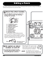
Editing a Patch
The patches of the B2.1u can be freely edited by changing the effect parameter settings. Try editing the
currently selected patch to create your own sound.
Select the effect module
Turn the Module selector to select the
effect module to edit. The following
settings are available.
(5)
(4)
(6)
(3)
(7)
(8)
(2)
(9)
(1)
(10)
(1) COMP/LIMIT module
(2) WAH/EFX module
(3) DRIVE/SYNTH module
(4) ZNR/MIX module
(5) LO EQ module
(6) HI EQ module
(7) MOD/SFX module
(8) DELAY module
(9) REVERB module
(10) Pedal/foot switch related parameters
When you switch to a different module, the effect
type currently selected for that module is shown on
the display. While the B2.1u is in edit mode, a dot
appears in the bottom right of the display.
Effect type
AG
Dot shows that unit
is in edit mode
To switch an effect
module on and off
To switch the selected module
between ON and OFF, press one
of the [W]/[Q] foot switches.
14
The indication "oF" appears on the
display. When you press one of the
foot switches again, the indication
returns to the previous condition.
HINT
OF
The ZNR/MIX module cannot be
turned off in this way. To disable ZNR,
set the effect parameter value to "oF".
ZOOM B2.1u
Editing a Patch
Terminate the edit mode
To terminate the edit mode and
return to the play mode, set the
Module selector to the "PLAY"
position.
NOTE
When you return to play mode
and select another patch, the
changes you have made in edit
mode will be lost unless you
store the patch first. To retain the
changes, store the patch as
described on page 16.
Change the parameter
value
To change the setting value of effect
parameters, use the Parameter knobs
1 – 3.
Which parameter is assigned to a knob depends on
which effect module/effect type is selected. For
information on parameters for effect
modules/effect types, see page 27 – 34.
When you turn a Parameter knob, the
corresponding LED lights up and the display
briefly shows the current value of the respective
parameter.
55
NOTE
When a module that is set to OFF is
selected, the display will show "oF".
Select the effect type
To switch the effect type of the selected module,
use the BANK [-]/[+] keys.
NOTE
SB
If you press the BANK [-]/[+] keys for a module that is set to OFF, the module
will be turned ON.
For modules that have only one effect type, pressing the BANK [-]/[+] keys
has no effect.
ZOOM B2.1u
15
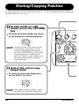
Storing/Copying Patches
An edited patch can be stored in a bank of the user area (A – d). It is also possible to store an existing patch
in another location to create a copy.
In play mode or edit
mode, press the [STORE]
key
The bank and patch number are shown
on the display as a flashing indication.
A0
NOTE
Patches of banks in the preset area (0 –
3) are read-only. No patches can be
stored or copied into these locations. If
you press the [STORE] key while a patch
from the preset area is selected, the
patch "A0" (bank A, patch number 0) will
be selected automatically as default
store/copy target.
Select the store/copy
target bank
To select the store/copy target bank,
use the BANK [-]/[+] keys.
D0
NOTE
16
Only a bank of the user area (A – d) can
be selected as store/copy target bank.
ZOOM B2.1u
Storing/Copying Patches
To cancel the store process
To cancel the store process, operate the
Module selector before pressing the [STORE]
key again ( ).
Press the [STORE]
key once more
When the store/copy process is
completed, the B2.1u returns to
the previous mode, with the target
patch being selected.
D4
Specify the store/copy target
patch number
To specify the store/copy target patch number, use
the [W]/[Q] foot switches.
D4
ZOOM B2.1u
17
Using the Built-in Expression Pedal
The expression pedal on the top panel of the B2.1u lets you adjust the effect sound or the volume in real
time during play. Which element is controlled by the pedal can be selected for each patch individually.
Select the patch for which the expression
pedal is to be used
Select the element to be
controlled by the
expression pedal
Press the [PEDAL ASSIGN]
key to select the element
to be controlled by the
expression pedal. The row
of LEDs above the key
shows which element is
currently selected.
The respective selection is indicated as follows.
• All LEDs are out
The expression pedal has no effect.
• VOLUME
The expression pedal controls the volume for the
entire patch.
• DRIVE MIX
MIX BALANCE parameter of ZNR/MIX module
• WAH/EFX, MOD/SFX, DELAY, REVERB
Respective module parameter
HINT
18
• Which parameter will be changed by the expression pedal depends on the
effect type selected for the respective module. For details, see pages 27 - 33.
• The pattern in which the parameter changes when the expression pedal is
operated can be selected in edit mode from four choices. For details, see page 34.
• If the module to which the expression pedal was assigned is set to OFF in the
patch, the LED flashes. In this case, operating the expression pedal has no
effect. If DRIVE MIX is selected, the LED flashes when the DRIVE/SYNTH
module (not the ZNR/MIX module) is off.
ZOOM B2.1u
Using the Built-in Expression Pedal
Operate the pedal
Move up or down
While playing your
instrument, move the
expression pedal up or down.
To switch a module
on or off
When you push the
expression pedal fully down,
the module selected with
the [PEDAL ASSIGN] key is
switched on or off.
Push fully down
Store the patch as necessary
The expression pedal setting can be stored for
each patch individually.
NOTE
If you select another patch in play mode without storing the
patch, any changes that you have made to the settings will
be lost.
ZOOM B2.1u
19
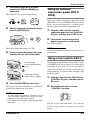
Other Functions
This section describes how to use the internal expression pedal as well as an external pedal or foot switch.
Use of the B2.1u as an audio interface or direct box is also explained.
Making settings for the
internal expression pedal
The built-in expression pedal on the top panel of
the B2.1u can function as a volume pedal or it can
be used to control an effect parameter in real time.
Which function is selected for the expression
pedal is stored for each patch individually.
For details on parameters that can be modified
with the expression pedal, see pages 27 – 33.
sound and effect sound of the DRIVE/SYNTH module
can be adjusted with the pedal. (If the DRIVE/SYNTH
module is set to OFF, the pedal has no effect. )
● MU, Md, MH, ML
MOD/SFX module
● dU, dd, dH, dL
DELAY module
● rU, rd, rH, rL
REVERB module
HINT
1.
Select the patch for which you want
to use the expression pedal.
• The modulation target can also be selected by
using the [PEDAL ASSIGN] key (→ p. 18). This
method is available both in edit mode and in play
mode.
2.
Set the Module selector to the
"CONTROL" position.
• Which parameter changes when the expression pedal
is operated depends on the effect type selected for
the module. For details, see pages 27 – 33.
• The pattern in which the parameter changes when the
expression pedal is operated can be selected in edit
mode from four choices. For details, see page 34.
The B2.1u goes into edit mode.
3.
Turn Parameter knob 1 to select one
of the following modulation targets
for the expression pedal (→ p. 34).
● oF
4. If necessary, store the patch.
The expression pedal setting is stored as part of
the patch.
5.
Select the patch in play mode and
operate the expression pedal.
The selected function will be activated.
When the B2.1u is in the bypass condition, the
expression pedal always functions as a volume
pedal, regardless of the setting made in step 3.
Pedal is inactive.
● VL
Volume
● WU, Wd, WH, WL
WAH/EFX module
● bU, bd, bH, bL
ZNR/MIX module
NOTE
When the modulation target is set to the ZNR/MIX
module, the mixing balance between the original
20
Adjusting the sensitivity of
the built-in expression pedal
The expression pedal of the B2.1u is adjusted for
optimum operation at the factory, but sometimes,
readjustment may be necessary. If the sound does
not change when the pedal is fully pushed down,
or if it changes excessively even if the pedal is
only lightly pushed, adjust the pedal as follows.
ZOOM B2.1u
Other Functions
1.
Turn power to the B2.1u on while
keeping the [PEDAL ASSIGN] key
depressed.
The indication "dn" appears on the display.
DN
2.
With the expression pedal fully raised,
press the [STORE] key.
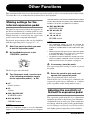
Using an external
expression pedal (FP01/
FP02)
When you connect an optional expression pedal
(FP01/FP02) to the [CONTROL IN] jack of the
B2.1u, you can use that pedal as a volume pedal,
separately from the built-in expression pedal.
1.
Plug the cable from the external
expression pedal into the [CONTROL
IN] jack, and then turn the B2.1u on.
2.
Operate the external expression
pedal in play mode or edit mode.
The volume changes.
The display indication changes to "UP".
3.
Push the expression pedal fully down
and then lift your foot off the pedal.
HINT
The external expression pedal always functions as a
volume pedal.
Using a foot switch (FS01)
Push strongly,
so that pedal touches
here.
When foot is lifted,
pedal returns slightly.
4. Press the [STORE] key once more.
The expression pedal adjustment is completed,
and the unit returns to the play mode.
Connecting an optional foot switch (FS01) to the
[CONTROL IN] jack of the B2.1u allows bank
switching in play mode. It is also possible to
switch bypass/mute on and off, control the tap
tempo function, or perform other functions with
the foot switch.
1.
Plug the cable from the FS01 into the
[CONTROL IN] jack, and then turn the
B2.1u on.
2.
Set the Module selector to the
"CONTROL" position.
HINT
• The point where the module is switched on or off
when the pedal is depressed is always the same,
regardless of the action taken in step 3.
• If "Er" appears on the display, repeat the procedure
from step 2.
The B2.1u goes into edit mode. You can now
make settings for the expression pedal or foot
switch.
ZOOM B2.1u
21
Other Functions
3.
Turn Parameter knob 2 to select one
of the following functions for the foot
switch.
● bP (bypass/mute)
The foot switch controls bypass or mute on/off.
This has the same effect as pressing both [W]/
[Q] foot switches at the same time in play
mode.
● dM (delay input mute)
The foot switch controls muting on/off for the
delay module input signal.
HINT
• For information on effect parameters supporting the
tap function, see pages 27 – 33.
• To use the hold function, an effect type that
supports the hold function must be selected in the
patch. For details, see page 33.
• While the delay module is set to hold or mute, the
dot in the center of the display flashes.
● tP (tap tempo)
Pressing the foot switch repeatedly can be used
to set the interval for the rhythm function or to
make settings for effect parameters supporting
the tap function. This has the same effect as
pressing the [TAP] key.
● bU (bank up)
Each push of the foot switch switches to the
next higher bank. This has the same effect as
pressing the BANK [+] key.
● rH (rhythm on/off)
The foot switch controls start/stop of the
rhythm function. This has the same effect as
pressing the RHYTHM [R/P] key.
● dH (delay hold)
The foot switch controls on/off of the delay
hold function. When a patch using the hold
function is selected, pressing the foot switch
will activate hold, causing the current delay
sound to be repeated (see illustration at the
bottom of this page). Pressing the foot switch
once more cancels the hold condition, and the
delay sound will decay normally.
4.
Select the patch in play mode and
operate the foot switch.
The selected function will be activated.
This function applies to all patches.
Using the B2.1u as audio
interface for a computer
By connecting the [USB] connector of the B2.1u
to a computer, the B2.1u can be used as an audio
interface with integrated AD/DA converter and
effects. The operating environment conditions for
this type of use are as follows.
■ Compatible operating system
• Windows XP
• MacOS X (10.2 or later)
■ Quantization
16-bit quantization
Original sound
Delay sound
Hold
Foot switch pressed
22
Pressed again
ZOOM B2.1u
Other Functions
■ Sampling frequency
audio tracks of the DAW application, mixed with
the guitar sound processed by the effects of the
B2.1u (see illustration at the bottom of this
page).
32 kHz / 44.1 kHz / 48 kHz
HINT
With each of the operating systems listed above, the
B2.1u will function as an audio interface simply by
connecting the USB cable. There is no need to install
any special driver software.
To use the B2.1u as an audio interface for the
computer, connect the [USB] connector of the
B2.1u to a USB port on the computer. The B2.1u
will be recognized as an audio interface.
HINT
• If the [POWER] switch of the B2.1u is set to OFF,
power will be supplied via the USB connection.
• If the [POWER] switch of the B2.1u is set to ON,
power will be supplied from the batteries in the
B2.1u or the AC adapter. Care should be taken
especially when running on battery power,
because setting the switch to ON may result in
faster depletion of the batteries.
In this condition, the sound of a guitar connected
to the [INPUT] jack of the B2.1u can be
processed with the effects of the B2.1u and then
recorded on the audio tracks of a DAW (Digital
Audio Workstation) software application on the
computer.
At the same time, the [OUTPUT/PHONES] jack
of the B2.1u carries the playback sound from the
For details on recording and playback, refer to
the documentation of the DAW application.
NOTE
• Also when using the B2.1u as an audio interface,
the signal after effect processing is always
available directly at the [OUTPUT/PHONES] jack.
• If the DAW application has an echo back function
(input signal during recording is supplied directly to
an output), this must be disabled when using the
B2.1u. If recording is carried out with this function
enabled, the output signal will sound as if
processed by a flanger effect.
• Use a high-quality USB cable and keep the
connection as short as possible. If power is
supplied to the B2.1u via a USB cable that is more
than 3 meters in length, the low voltage warning
indication may appear.
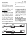
Use as a direct box
The [BALANCED OUT] connector on the rear
panel lets you use the B2.1u as a direct box for
sending the bass signal directly to a PA mixer or
recording console. (Gain: 0 dB, output
impedance: 200 ohms, HOT-COLD)
DAW
application
B2.1u
[INPUT]
[OUTPUT/PHONES]
Effects
USB
[USB]
Record
B2.1u
[INPUT]
DAW
application
Effects
USB
[OUTPUT/PHONES]
ZOOM B2.1u
[USB]
Playback
23
Restoring Factory Defaults
To use this function, connect the [BALANCED
OUT] connector of the B2.1u to the PA mixer or
recording console, using XLR balanced cable. At
the same time, you can also connect the
[OUTPUT/PHONES] jack to the bass amplifier
for monitoring. (The amp settings will have no
effect on the signal supplied at the [BALANCED
OUT] connector.)
[BALANCED OUT]
connector
Mixer
B2.1u
processing, select the "PRE" position (switch
disengaged).
In certain configurations, a ground loop (electrical
signal loop created because devices within the
same system are connected to a separate ground)
may occur, leading to noise problems (audible
hum). In such a case, try setting the [GROUND]
switch to "LIFT". This may help to eliminate or
reduce the noise.
Bass guitar [OUTPUT/PHONES]
jack
HINT
Bass amp
The [PRE/POST] switch lets you control the type
of signal supplied at the [BALANCED OUT]
connector. To use the signal after effect
processing, select the "POST" position (switch
engaged). To use the signal before effect
The [GROUND] switch determines whether the
[BALANCED OUT] connector is grounded or not.
When the switch is set to the "LIFT" position (switch
engaged), the ground pin of the [BALANCED OUT]
connector is uncoupled from the signal path. This can
be effective in eliminating or reducing hum noise
caused by a ground loop.
Restoring Factory Defaults
In the factory default condition, the patches of the user area (A0 – d9) contain the same settings as the
patches of the preset area (00 – 39). Even after overwriting the user patches, their original content can be
restored in a single operation ("All Initialize" function).
1.
Turn the B2.1u on while holding down
the [STORE] key.
The indication "AL" appears on the display.
AL
2.
24
To carry out the All Initialize function,
press the [STORE] key once more.
All patch settings are returned to the factory
default condition, and the unit switches to play
mode. To cancel All Initialize, press the
RHYTHM [R/P] key instead of the [STORE]
key.
NOTE
When you carry out All Initialize, any newly created
patches that were stored in the user area will be
deleted (overwritten). Perform this operation with care
to prevent losing any patches that you want to keep.
ZOOM B2.1u
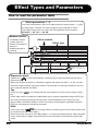
Linking Effects
The patches of the B2.1u consist of nine serially linked effect modules, as shown in the illustration below.
You can use all effect modules together or selectively use certain modules by setting them to on or off.
Effect module
COMP/LIMIT
WAH/EFX
DRIVE/SYNTH
ZNR/MIX
LO EQ
HI EQ
MOD/SFX
DELAY
COMPRESSOR
AUTO WAH
AMPEG
ZNR
LO EQ
HI EQ
CHORUS
DELAY
HALL
LIMITER
AUTO
RESONANCE
FILTER
SUPER BASS
LO
PARAMETRIC
EQ
HI
PARAMETRIC
EQ
STEREO
CHORUS
PINGPONGDELAY
ROOM
FLANGER
ECHO
OCTAVE
ACOUSTIC
TREMOLO
BASSMAN
PEDAL
PITCH
PHASER
HARTKE
VIBRATO
RING
MODULATOR
TRACE ELLIOT
STEP
TUBE PRE
DELAY
SANSAMP
TAPE ECHO
TS9
PITCH
SHIFTER
SWR
REVERB
SPRING
Effect type
DEFRET
PEDAL WAH
ODB-3
MXR BASS D.I+
HARMONIZED
PITCH
SHIFTER
FUZZ FACE
STDSYN
SYNTLK
MONO SYN
* Manufacturer names and product names mentioned in this table are trademarks or
registered trademarks of their respective owners. The names are used only to illustrate
sonic characteristics and do not indicate any affiliation with ZOOM CORPORATION.
For some effect modules, you can select an effect
type from several possible choices. For example,
the COMP/LIMIT module gives a choice between
COMPRESSOR, LIMITER, and other effect
types. The REVERB module comprises HALL,
ROOM, and other effect types from which you
can choose one. Because the ZNR/MIX module
has only one effect type, you cannot choose the
type for this module.
HINT
• The mixing balance of the DRIVE/SYNTH module
original sound and the effect sound/synth sound, as
well as the signal level after passing the module can
be adjusted with the ZNR/MIX module.
• When "STDSYN", "SYNTLK", or "MONO SYN" is
selected as effect type for the DRIVE/SYNTH
module, the action of the COMP/LIMIT module and
WAH/EFX module (connection position set to "bF")
will apply only to the original sound after passing
the DRIVE/SYNTH module and not to the synth
sound.
• The ZNR/MIX module cannot be turned off with the
foot switch. To disable ZNR, set the effect
parameter value to "oF".
• The DRIVE/SYNTH module has a "CABINET"
parameter that controls how the speaker cabinet
characteristics are reproduced. This allows you to
match the cabinet character effect to various
requirements of a live performance or of direct
recording.
ZOOM B2.1u
25
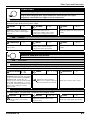
Effect Types and Parameters
How to read the parameter table
Effect parameters 1 – 3
These are the parameters that can be adjusted with Parameter knobs 1 – 3 when
the effect type is selected. The setting range for each parameter is shown.
Three-digit setting values are shown with a dot between the two numerals.
Example: 1 – 98, 1.0 = 1 – 98, 100
Module selector
The Module selector
symbol shows the
position of the knob at
which this
module/parameter is
called up.
Effect module
Effect type
DELAY
DELAY module
DL
dL
This is a delay module which allows long delay times and use of the hold function.
DELAY
HOLD This is a delay with a maximum setting of 5000 ms.
PD
Pd
PINGPONG DELAY
HOLD This is a ping-pong type delay where the delay sound alternates between left and right.
EC
EC
ECHO
HOLD This effect simulates a tape echo with a long delay time of up to 5000 ms.
These three effect types have the same parameters.
TIME
1 – 99,
1.0 – 5.0
FEEDBACK
0 – 98, 1.0
MIX
0 – 98, 1.0
TAP Adjusts the delay time. In the
range from 10 – 990 ms, the
adjustment is made in 10-ms
steps (1 – 99). For 1 second and
above, the adjustment is made in
100-ms steps (1.0 – 2.0).
Adjusts the feedback amount.
Adjusts the mixing ratio of
original sound and effect sound.
Expression pedal
A pedal icon (
) in the listing indicates a parameter that can be controlled with the built-in
expression pedal.
Specify the respective module as modulation target for the expression pedal (→ p. 20), and then
select the respective effect type of the module. The parameter can then be controlled in real time
with a connected expression pedal.
Tap
TAP
A [TAP] key icon (
) in the listing indicates a parameter that can be set by hitting the [TAP]
key.
In edit mode, when the respective module/effect type is selected, repeatedly hitting the [TAP] key
will set the parameter according to the key press interval (modulation cycle, delay time, etc.).
In play mode, if the DELAY module is ON for the currently selected patch, repeatedly hitting the
[TAP] key will temporarily change the parameter.
Hold
HOLD
A foot switch icon (
) in the listing indicates an effect type for which hold can be turned
on and off with the foot switch (FS01).
Set the foot switch function to "dH" (delay hold) (→ p. 22) for the respective patch. When this patch
is then selected in play mode, the hold function can be switched on and off by pressing the foot
switch.
26
ZOOM B2.1u
Effect Types and Parameters
COMP/LIMIT
COMP/LIMIT (Compressor/Limiter) module
This module includes a compressor that keeps the overall signal level within a certain
range by attenuating high-level signal components or boosting low-level signal
components, and a limiter that suppresses peak components.
COMPRESSOR
CP CP
The compressor attenuates high-level signal components and boosts low-level signal components to keep
the overall signal level within a certain range.
SENSE
0 – 10
Adjusts the compressor sensitivity.
Higher setting values result in higher
sensitivity.
ATTACK
LEVEL
1 – 10
Adjusts the time between the sound
attack point and the start of
compression. Higher setting values
result in faster compression action.
2 – 98, 1.0
Adjusts the signal level after passing the
module.
LIMITER
LM LM
This is a limiter that suppresses signal peaks above a certain reference level.
THRESHOLD 0 – 10
Adjusts the reference signal level for the
limiter action.
RATIO
1 – 10
Adjusts the limiter intensity. Higher
setting values result in stronger
compression of the input signal.
LEVEL
2 – 98, 1.0
Adjusts the signal level after passing the
module.
WAH/EFX
WAH/EFX (Wah/Effects) module
Comprises wah and filter effects as well as VCA type effects.
AW
AW
AUTO WAH
This effect varies wah in accordance with playing intensity.
AUTO RESONANCE FILTER
AR Ar
This effect varies the frequency band of the resonance filter according to the picking intensity.
The two effect types above have the same parameters.
POSI & DIR MIX b0 – b9,
A0 – A9
Selects the connection position of the
WAH/EFX module. The b0 - b9 settings
specify connection before the DRIVE/
SYNTH module, and the A0 - A9
settings specify connection after the HI
EQ module. The numbers 0 - 9 specify
the original sound mixing balance, with
higher values resulting in stronger
original sound.
SENSE
-10 – -1, 1 – 10
Adjusts the effect sensitivity.
When set to a negative value, the
filter characteristics are inverted.
RESONANCE 0 – 10
Adjusts the resonance of the sound.
OCTAVE
OC oC
This effect adds a 1-octave lower component to the original sound.
OCT LVL
0 – 98, 1.0
Adjusts the mixing balance of the
effect sound (1-octave lower
sound).
ZOOM B2.1u
DIR LVL
0 – 98, 1.0
Adjusts the mixing balance of the
original sound.
TONE
0 – 10
Adjusts the sound quality after mixing.
27
Effect Types and Parameters
TREMOLO
TR tr
This effect periodically varies the volume.
DEPTH
0 – 98, 1.0
Adjusts the modulation depth.
RATE
0 – 50
TAP Adjusts the effect rate.
u0 – u9, d0 –
d9, t0 – t9
Allows selection of the modulation
waveform. Available settings are "u"
(rising sawtooth), "d" (falling sawtooth),
and "t" (triangular). Higher setting
values result in more clipping of wave
peaks, which reinforces the effect.
WAVE
PHASER
PH PH
This effect produces sound with a pulsating character.
POSITION
bF, AF
Selects the connection position of the
WAH/EFX module. The bF setting
specifies connection before the DRIVE/
SYNTH module, and the AF setting
specifies connection after the HI EQ
module.
RATE
0 – 50
TAP Adjusts the modulation rate.
COLOR
1–4
Adjusts the type of sound.
RING MODULATOR
RG rG
This effect produces a metallic ringing sound. Adjusting the FREQUENCY parameter results in a drastic
change of sound character.
POSITION
bF, AF
Selects the connection position of the
WAH/EFX module. The bF setting
specifies connection before the DRIVE/
SYNTH module, and the AF setting
specifies connection after the HI EQ
module.
FREQUENCY
1 – 50
Adjusts the frequency that is used for
modulation.
BALANCE
0 – 98, 1.0
Adjusts the balance between the
original sound and the effect
sound.
DEFRET
DF dF
This effect changes the sound of any bass into a sound resembling a fretless bass.
SENSE
0 – 30
Adjusts the effect sensitivity.
TONE
1 – 50
Adjusts the sound quality.
COLOR
1 – 10
Adjusts the amount of harmonics.
Higher setting values result in stronger
sonic character.
PEDAL WAH
PW PW
Simulates a Vox wah pedal
POSI & DIR MIX b0 – b9,
A0 – A9
Selects the connection position of the
WAH/EFX module. The b0 - b9 settings
specify connection before the DRIVE/
SYNTH module, and the A0 - A9
settings specify connection after the HI
EQ module. The numbers 0 - 9 specify
the original sound mixing balance, with
higher values resulting in stronger
original sound.
28
FREQUENCY
1 – 50
Adjusts the frequency that is
emphasized. When no expression
pedal is used, the effect is the
same as with a half-raised pedal.
LEVEL
2 – 98, 1.0
Adjusts the signal level after passing the
module.
ZOOM B2.1u
Effect Types and Parameters
DRIVE/SYNTH
DRIVE/SYNTH module
This module provides special effects such as 13 types of amp and stomp box simulations
and a synth bass sound. The mixing balance of original sound and effect sound/synth
sound, and the signal level after passing the module are adjusted with the ZNR/MIX module.
* Manufacturer names and product names mentioned in this table are trademarks or registered trademarks
of their respective owners. The names are used only to illustrate sonic characteristics and do not indicate
any affiliation with ZOOM CORPORATION.
AMPEG
AG AG
Simulation of the AMPEG SVT that is one of the most
popular bass guitar amps in Rock.
SWR
SW SW
Simulation of the SWR SM-900 famous for its hi-fi
sound.
BASSMAN
BM bM
Simulation of the FENDER BASSMAN 100.
SUPER BASS
SB Sb
Simulation of the MARSHALL SUPER BASS, a
milestone in the history of Rock.
ACOUSTIC
AC AC
Simulation of the ACOUSTIC 360 known for its
special midrange sound.
HARTKE
HA HA
Simulation of the HARTKE HA3500 famous for its
aluminum cone.
TRACE ELLIOT
TE tE
Simulation of the TRACE ELLIOT AH-500.
All above effect types have the same parameters.
CABINET
TU
tU
TONE
oF, 1 – 3
With the "oF" setting, only the head amp
characteristics are applied. A numeric
setting adds cabinet sound of differing
intensity as well.
0 – 10
Adjusts the sound quality.
TUBE PRE
ZOOM original tube preamplifier sound.
TS9
TS tS
Simulation of the Tube Screamer used by many
guitarists as a booster.
MXR BASS D.I. +
DS dS
Simulation of the distortion channel of the MXR Bass
D.I.+.
GAIN
0 – 98, 1.0
Adjusts the distortion intensity.
SANSAMP
SA SA
Simulation of the SANSAMP BASS DRIVER DI, very
popular among bassists.
ODB-3
OD od
Simulation of the Boss Overdrive ODB-3 for bass
guitar.
FUZZ FACE
FF FF
Simulation of the Fuzz Face that made rock history
with its zany look.
All above effect types have the same parameters.
CABINET
oF, 1 – 3
With the "oF" setting, only the stomp
box characteristics are applied. A
numeric setting adds cabinet sound of
differing intensity as well.
TONE
0 – 10
Adjusts the sound quality.
GAIN
0 – 98, 1.0
Adjusts the distortion intensity.
STDSYN (Standard Synth)
SS SS
ZOOM standard synth bass sound.
CABINET
oF, 1 – 3
Numeric settings select different cabinet
types.
ST
VARI
1–4
Selects the synth sound variation.
SENSE
0 – 98, 1.0
Adjusts the trigger detection sensitivity.
St
SYNTLK (Synth Talk)
This effect produces a synth sound like a talking modulator using vowels for vocalization.
CABINET
oF, 1 – 3
Numeric settings select different cabinet
types.
ZOOM B2.1u
VARI
iA, UE, UA, oA
Selects the type of vocalization.
DECAY
0 – 98, 1.0
Adjusts the rate of sound change.
29
Effect Types and Parameters
MONO SYN (Mono Synth)
MS MS
This is a monophonic (single-note) bass synthesizer that detects the input signal pitch.
CABINET
oF, 1 – 3
Numeric settings select different cabinet
types.
s1 – s5, p1 –
p5, m1 – m5
Selects the waveform type and sound
variation. "s" produces a sawtooth wave,
"p" produces a square wave, and "m"
uses PWM (pulse width modulation).
VARI
DECAY
0 – 98, 1.0
Adjusts the rate of sound change.
ZNR/MIX
ZNR/MIX module
This module serves for reducing noise during playing pauses. The module also is used to
control the mixing balance of original sound and effect sound for the DRIVE/SYNTH
module, and the signal level after the module. The ZNR/MIX module cannot be turned off
with the foot switch. To disable ZNR, set the effect parameter value to "oF".
ZNR (ZOOM Noise Reduction)
NR nr
This is ZOOM's original noise reduction that suppresses noise in playing pauses without affecting the tonal
quality of the sound. Also allows adjusting the mixing balance and level of the DRIVE/SYNTH module.
ZNR
LEVEL
MIX BALANCE 0 – 98, 1.0
oF, Z0 – Z9
Adjusts the mixing balance
between the signal before input to
the DRIVE/SYNTH module and
the signal after passing the
module. Higher setting values
result in stronger WET sound.
When the DRIVE/SYNTH
module is set to Off, the
indication "oF" is shown.
Adjusts the ZNR sensitivity. For
maximum noise reduction, set the value
as high as possible without causing the
sound to cut in or decay unnaturally.
2 – 98, 1.0
Adjusts the signal level after passing the
DRIVE/SYNTH module. When the
DRIVE/SYNTH module is set to Off,
the indication "oF" is shown.
LO EQ
LO EQ module
This is an equalizer for the low frequency range. You can select either a 3-band equalizer
or parametric equalizer.
LO EQ (Low EQ)
LE LE
This is a 3-band equalizer that adjusts the frequency range below 450 Hz.
70Hz
±12
70 Hz, shelving type equalizer.
150Hz
450Hz
±12
150 Hz, peaking type equalizer.
±12
450 Hz, peaking type equalizer.
LO PARAMETRIC EQ (Low Parametric EQ)
LP LP
This is a parametric equalizer that adjusts the frequency range below 650 Hz.
TYPE
1, 2, SH
Selects the type of filter. "1" gives a
peaking type filter with narrow Q, "2"
gives a peaking type filter with wide Q,
and "SH" produces a shelving type LO
EQ.
FREQUENCY See Table 1
Selects a frequency within the range of
100 - 650 Hz.
Table 1
Display
10
25
35
30
Frequency
100Hz
250Hz
350Hz
Display
50
65
GAIN
±12
Adjusts the gain.
Frequency
500Hz
650Hz
ZOOM B2.1u
Effect Types and Parameters
HI EQ
HI EQ module
This is an equalizer for the high frequency range. You can select either a 3-band equalizer
or parametric equalizer.
HI EQ (High EQ)
HE HE
This is a 3-band equalizer that adjusts the frequency range above 1 kHz.
1kHz
3kHz
±12
1 kHz, peaking type equalizer.
6kHz
±12
3 kHz, peaking type equalizer.
±12
6 kHz, shelving type equalizer.
HI PARAMETRIC EQ (High Parametric EQ)
HP HP
This is a parametric equalizer for the frequency range above 800 Hz.
TYPE
FREQUENCY See Table 2
1, 2, SH
Selects the type of filter. "1" gives a
peaking type filter with narrow Q, "2"
gives a peaking type filter with wide Q,
and "SH" produces a shelving type LO
EQ.
GAIN
Selects a frequency within the range of
800 Hz – 4.8 kHz.
Table 2
Display
80
1.2
2.4
Frequency
800Hz
1.2kHz
2.4kHz
Display
3.6
4.8
±12
Adjusts the gain.
Frequency
3.6kHz
4.8kHz
MOD/SFX
MOD/SFX(Modulation/SFX) module
Comprises modulation and delay effects such as chorus, pitch shifter, delay, and echo.
CHORUS
This effect mixes a variable pitch-shifted component to the original signal, resulting in full-bodied resonating sound.
CH
CH
DEPTH
RATE
0 – 98, 1.0
1 – 50
Adjusts the modulation rate.
Adjusts the modulation depth.
MIX
0 – 98, 1.0
Adjusts the level of the effect sound
mixed to the original sound.
STEREO CHORUS
SC SC
This is a stereo chorus with clear sound.
DEPTH
0 – 98, 1.0
Adjusts the modulation depth.
RATE
1 – 50
Adjusts the modulation rate.
MIX
0 – 98, 1.0
Adjusts the level of the effect
sound mixed to the original sound.
FLANGER
FL FL
This effect produces a resonating and strongly undulating sound.
DEPTH
0 – 98, 1.0
Adjusts the modulation depth.
ZOOM B2.1u
RATE
0 – 50
TAP Adjusts the modulation rate.
RESONANCE -10 – -1, 0,
1 – 10
Adjusts the modulation resonance
intensity.
31
Effect Types and Parameters
PEDAL PITCH
PP PP
This effect allows using a pedal to shift the pitch in real time.
COLOR
See Table 3
Selects the type pitch change type
effected by the pedal.
Table 3
COLOR MODE
1
2
3
4
Pedal minimum value
UP
-100 cent
dn Original sound only
DOUBLING
UP
Detune + DRY
dn
0 cent
UP
+1 octave
dn
0 cent
UP
-2 octaves
dn
MODE
TONE
UP, dn
Selects the direction of the pitch change.
Pedal maximum value COLOR MODE
Original sound only
UP
5
-100 cent
dn
Detune + DRY
UP
6
DOUBLING
dn
+1 octave
UP
7
0 cent
dn
-2 octaves
UP
8
0 cent
dn
0 – 10
Adjusts the sound quality.
Pedal minimum value
-1 octave + DRY
+1 octave + DRY
-700 cent + DRY
500 cent + DRY
-∞ (0 Hz) + DRY
+1 octave
-∞ (0 Hz) + DRY
+1 octave + DRY
Pedal maximum value
+1 octave + DRY
-1 octave + DRY
500 cent + DRY
-700 cent + DRY
+1 octave
-∞ (0 Hz) + DRY
+1 octave + DRY
-∞ (0 Hz) + DRY
VIBRATO
VB Vb
Effect with automatic vibrato.
DEPTH
0 – 98, 1.0
Adjusts the modulation depth.
RATE
0 – 50
TAP Adjusts the modulation rate.
BALANCE
0 – 98, 1.0
Adjusts the balance between original
sound and effect sound.
STEP
ST St
Special effect that changes the sound in a staircase pattern.
DEPTH
0 – 98, 1.0
Adjusts the modulation depth.
RATE
0 – 50
TAP Adjusts the modulation rate.
RESONANCE 0 – 10
Adjusts the modulation resonance
intensity.
DELAY
DL dL
This is a delay with a maximum setting of 2000 ms.
1 – 99,
1.0 – 2.0
TAP Adjusts the delay time. In the range
from 10 – 990 ms, the adjustment is
made in 10-ms steps (1 – 99). For 1
second and above, the adjustment is
made in 100-ms steps (1.0 – 2.0).
TIME
FEEDBACK
0 – 98, 1.0
Adjusts the feedback amount.
MIX
0 – 98, 1.0
Adjusts the level of the effect
sound mixed to the original
sound.
TAPE ECHO
TE tE
This effect simulates a tape echo.
1 – 99,
1.0 – 2.0
TAP Adjusts the delay time. In the range
from 10 – 990 ms, the adjustment is
made in 10-ms steps (1 – 99). For 1
second and above, the adjustment is
made in 100-ms steps (1.0 – 2.0).
TIME
FEEDBACK
0 – 98, 1.0
Adjusts the feedback amount.
MIX
0 – 98, 1.0
Adjusts the level of the effect
sound mixed to the original
sound.
PITCH SHIFTER
PT Pt
This effect shifts the pitch of the original sound up or down.
-12 – -1, dt,
1 – 12, 24
Adjusts the pitch shift amount in semitones.
Selecting "dt" gives a detuning effect.
SHIFT
32
TONE
0 – 10
Adjusts the sound quality.
BALANCE
0 – 98, 1.0
Adjusts the balance between
original sound and effect sound.
ZOOM B2.1u
Effect Types and Parameters
HARMONIZED PITCH SHIFTER
HP HP
This is an intelligent pitch shifter that automatically generates harmonies according to a preset key and
scale.
-6, -5, -4, -3,
-m, m, 3, 4,
5, 6
Determines the interval for the pitch
shifted sound (see Table 4).
KEY
SCALE
Table 4
Setting Type of scale
Interval
Sixth down
-6
Fifth down
-5
Major scale
Fourth down
-4
Third down
-3
Third down
-m
Minor scale
Third up
m
C, Co, d...b
Determines the tonic for the scale used
for pitch shifting (see Table 5).
Setting Type of scale
3
4
Major scale
5
6
Interval
Third up
Fourth up
Fifth up
Sixth up
MIX
0 – 98, 1.0
Adjusts the level of the effect sound
mixed to the original sound.
Table 5
Setting
C
Co
d
do
E
F
Tonic Setting
C
Fo
C#
G
D
Go
D#
A
E
Ao
F
b
Tonic
F#
G
G#
A
A#
B
DELAY
DELAY module
This is a delay module which allows long delay times and use of the hold function.
DL
dL
DELAY
HOLD This is a delay with a maximum setting of 5000 ms.
PD
Pd
PINGPONG DELAY
HOLD This is a ping-pong type delay where the delay sound alternates between left and right.
EC
EC
ECHO
HOLD This is a warm sounding long delay of up to 5000 ms duration.
These three effect types have the same parameters.
1 – 99,
1.0 – 5.0
TAP Adjusts the delay time. In the
range from 10 – 990 ms, the
adjustment is made in 10-ms
steps (1 – 99). For 1 second and
above, the adjustment is made in
100-ms steps (1.0 – 5.0).
TIME
FEEDBACK
0 – 98, 1.0
Adjusts the feedback amount.
MIX
0 – 98, 1.0
Adjusts the level of the effect
sound mixed to the original
sound.
REVERB
REVERB module
This is a module with various kinds of reverb effects.
HALL
This reverb simulates the acoustics of a concert hall.
ROOM
RM rM
This reverb simulates the acoustics of a room.
SPRING
SP SP
This effect simulates a spring-type reverb.
HL
HL
The above three effect types have the same parameters.
DECAY
1 – 30
Adjusts the duration of the reverb.
ZOOM B2.1u
TONE
0 – 10
Adjusts the sound quality.
MIX
0 – 98, 1.0
Adjusts the level of the effect sound
mixed to the original sound.
33
Effect Types and Parameters
CONTROL
CONTROL module
Serves for making pedal settings and lets you control the foot switch function and master
level setting applying to all patches.
FS
RTM DESTINATION See Table 6
Selects the modulation target module
that is controlled with the built-in
expression pedal (see Table 6).
MASTER LEVEL 0 – 98, 1.0
See Table 7
When a foot switch (FS01) is connected
to the [CONTROL IN] jack, this selects
the function that can be operated with
the foot switch (See Table 7). The
function selected here applies to all
patches.
Adjusts the master level for all patches.
RTM (Real Time Modulation): The effect parameter can be changed with the expression pedal in real time.
Table 6
Setting
oF
VL
WU, Wd, WH, WL
bU, bd, bH, bL
MU, Md, MH, ML
dU, dd, dH, dL
rU, rd, rH, rL
Modulation target
OFF
Volume
WAH/EFX module (*)
ZNR/MIX module (*)
MOD/SFX module (*)
DELAY module (*)
REVERB module (*)
Table 7
Setting
bP
tP
bU
rH
dH
dM
The operation of modules denoted by (*) changes as
follows, according to the letter at right.
U UP
The parameter is at minimum when the pedal is fully raised and
at maximum when the pedal is fully pushed down.
D DOWN
The parameter is at maximum when the pedal is fully raised and
at minimum when the pedal is fully pushed down.
Function
Bypass/Mute
Tap tempo
Bank up
Rhythm function on/off
Delay hold
Delay mute
"UP"
Maximum value
Minimum value
"DOWN"
Maximum value
Minimum value
H HIGH
When the pedal is fully raised, the parameter is at the value set in
the patch. When the pedal is fully pushed down, the parameter is
at maximum.
"HIGH"
Maximum value
Value set in patch
L LOW
When the pedal is fully raised, the parameter is at minimum.
When the pedal is fully pushed down, the parameter is at the
value set in the patch.
"LOW"
Value set in patch
HINT
When the ZNR/MIX module is selected as modulation target, the pedal
adjusts the mixing balance of the DRIVE/SYNTH module (→ p. 30).
34
Minimum value
ZOOM B2.1u
Specifications
Effect types
47
Effect modules
Max. 9 simultaneous modules
Patches
User area: 10 patches x 4 banks
Preset area: 10 patches x 4 banks
Sampling frequency
96 kHz
A/D converter 24 bit, 64 times oversampling
D/A converter 24 bit, 128 times oversampling
Signal processing
32 bit
Frequency response
20 Hz – 40 kHz +1 dB -3 dB
(with 10 kilohms load)
Display
2-digit 7-segment LED
Parameter LEDs,
Pedal assign LEDs
Input
Standard mono phone jack
Rated input level
-20 dBm
Input impedance
1 megohm
Output
Standard stereo phone jack
(doubles as line and headphone jack)
Maximum output level
+5 dBm (output load impedance
10 kilohms or more)
Maximum phones output level
20 mW + 20 mW
(into 32 ohms load)
XLR jack (balanced output)
Input/output gain
0 dB
Output impedance
100 ohms
(HOT-GND)
(COLD-GND)
200 ohms
(HOT-COLD)
Control input For FP02 (FP01) /FS01
USB interface
PC interface: 16-bit (stereo configuration for
recording/playback)
Sampling frequency:
32 kHz, 44.1 kHz, 48 kHz
Power requirements
AC adapter 9 V DC, 300 mA (center minus
plug) (ZOOM AD-0006)
Batteries
Four IEC R6 (size AA) batteries,
Approx. 6 hours continuous
operation (alkaline batteries)
Dimensions
165 mm (D) x 255 mm (W) x
79mm (H)
Weight
1200 g (without batteries)
Options
Expression pedal FP02/
Foot switch FS01
• 0 dBm = 0.775 Vrms
• Design and specifications subject to change without
notice.
Troubleshooting
● No power
Refer to "Turn power on" on page 8.
● Reverb effect does not operate
While a rhythm pattern is playing, the reverb
effect is not available. Stop the rhythm pattern
first (→ p. 12).
● No effect processing occurs (when
using [BALANCED OUT] connector)
Check whether the [PRE/POST] switch is set to
POST (signal after effect processing).
● High level of noise
Is ZOOM AC adapter being used? Be sure to use
ZOOM B2.1u
only adapter for 9 V DC, 300 mA with center
minus plug (ZOOM AD-0006).
● High-level noise is heard (when using
[BALANCED OUT] connector)
A ground loop may have been created among
connected devices. Check whether setting the
[GROUND] switch to "LIFT" results in an
improvement.
● Battery life is short
Are manganese batteries being used? The use of
alkaline batteries is recommended.
35
B2.1u Preset Pattern
#
PatternName
TimSig
#
4/4
21
POP_3
4/4
8beat_2
4/4
22
DANCE_1
4/4
3
8beat_3
4/4
23
DANCE_2
4/4
4
8shufle
4/4
24
DANCE_3
4/4
5
16beat_1
4/4
25
DANCE_4
4/4
6
16beat_2
4/4
26
3per4
3/4
7
16shufle
4/4
27
6per8
3/4
8
ROCK
4/4
28
5per4_1
5/4
9
HARD
4/4
29
5per4_2
5/4
10
METAL_1
4/4
30
LATIN
4/4
11
METAL_2
4/4
31
BALLAD_1
4/4
12
THRASH
4/4
32
BALLAD_2
3/4
13
PUNK
4/4
33
BLUES_1
4/4
14
DnB
4/4
34
BLUES_2
3/4
15
FUNK_1
4/4
35
JAZZ_1
4/4
16
FUNK_2
4/4
36
JAZZ_2
3/4
17
HIPHOP
4/4
37
METRO_3
3/4
18
R'nR
4/4
38
METRO_4
4/4
19
POP_1
4/4
39
METRO_5
5/4
20
POP_2
4/4
40
METRO
1
8beat_1
2
PatternName
TimSig
ZOOM CORPORATION
ITOHPIA Iwamotocho 2chome Bldg. 2F, 2-11-2, Iwamoto-cho,
Chiyoda-ku, Tokyo 101-0032, Japan
Web Site: http://www.zoom.co.jp
B2.1u - 5000-1
B2.1u Patch List
Description
No. Patch name
AMPEG
VOLUME
Phaser sound lets you embellish your slap playing with modulation effects.
PHASER
PHASER
RATE
A2 Barred
All-rounder distortion sound is great for chord or lead playing. Turn on pedal wah, flanger, and echo for even more excitement.
ODB-3
FLANGER
RATE (OFF)
A3 AUTO WAH
Traditional-style auto wah with many applications. Transform percussive play with ghost notes straight into a funky sound.
AUTO WAH
AUTO WAH
SENSE
A4 Yes!
Progressive rock sound, taking a hint from Yes bassist Chris Squire.
CHORUS &
ECHO
ECHO MIX
Marcus Miller type slap sound. Typically deep SWR bass amplifier sound is complemented by glossy highs.
SWR
DELAY MIX
A6 Sublime
Sub bass sound such as used for Techno, Electronica, and Drum'n Bass. Experience a sine wave so low it seems to hug the ground.
MONO SYN
& PHASER
PHASER
RATE
A7 Tremolo
Enchanting tremolo sound with reverb creates a dreamy backdrop or enhances a moody solo.
TREMOLO
TREMOLO
RATE
A8 No Worries
A1
PHASER
SLAP
DEMO
No Holds
A5
Miller's
Crossing
Fretless bass sound using the defret effect. Add a slide to a phrase and turn your instrument into a fretless bass.
DEFRET
ROOM MIX
A9 DELAY
Collaboration of synth and step may surprise at first, but will show its potential when played with long tones.
MONO SYN
& STEP
STEP RATE
B0 SVT
Combines the all-tube SVT from AMPEG with an 810E cabinet. Experience that gutsy tube amp sound.
AMPEG
VOLUME
B1 SWR
SWR sound modeled on a SM-900 head amp combined with the Goliath cabinet. Rich low range and clear highs are bound to impress.
SWR
VOLUME
B2 BASS
Simulation of MARSHALL 1992 SuperBass head amp combined with 1935A cabinet, tailored into Marshall style driveoriented sound.
SUPER
BASS
VOLUME
B3 TRACE
Simulation of TRACE ELLIOT head amp AH-500 combined with two cabinets (1048H & 1518), producing the typical
midrange character of British rock.
TRACE
ELLIOT
VOLUME
B4 BASSMAN
Simulates the Fender Bassman 100 used by Paul McCartney. Enjoy that special Beatles sound with Rickenbacker or Hofner
basses.
BASSMAN
VOLUME
B5 ACOUSTIC
Simulation of ACOUSTIC 360 head amp combined with 301 cabinet, characterized by a tight midrange.
ACOUSTIC
VOLUME
B6 HARTKE
Simulation of HARTKE HA3500 head amp combined with aluminum-cone cabinet 4.5XL. Note the characteristically
straightforward punch of aluminum.
HARTKE
VOLUME
B7 TUBE
Simulates a high-class tube preamplifier such as used in recording studios. The fat and supple sound fits every genre.
TUBE PRE
VOLUME
B8 SANSAMP
Simulates the lightly distorted sound of the SANSAMP BASSDRIVER DI, beloved by many bass players.
SANSAMP
DRIVE MIX
B9 SCREAMER
Simulation of the Tube Screamer used by many guitarists as a booster. Get that cool overdrive sound, whether picking or fingering.
TS9
DRIVE MIX
C0 MXR
Simulates the MXR BASS D.I. + distortion channel. A gutsy low end plus the right amount of original sound creates distortion
with a solid core.
MXR BASS
D.I.+
PEDAL
PITCH 2oct
DOWN
C1 ODB
Simulates the ODB-3 overdrive bass machine from Boss. Proper mixing of original sound gives fat overdrive without losing
bass response.
ODB-3
DRIVE MIX
C2 FUZZ FACE
Simulates the Fuzz Face famous for its unique look. Push down the pedal to get wildly distorted fuzz sound, great for those
aggressive bass lines.
FUZZ FACE
DRIVE MIX
C3 Slang
Chorus sound often used by Jaco Pastorius in the late seventies. Lets you play his "Slang" loop solos with hold delay.
CHORUS &
ACOUSTIC
ROOM MIX
C4 Slapstick
Rock style sound as personified by Flea of the Red Hot Chili Peppers. Use a StingRay or Modulus bass and whip up some slap
bass action.
AMPEG
ROOM MIX
C5 BootSea
Bootsy Collins sound using auto wah. Dress up in a fancy costume, wear star-shaped sunglasses, and let it rip!
AUTO WAH
& PITCH
PITCH SHIFTER
BALANCE
C6 Mo'Soul
Motown sound made famous by James Jamerson. Sixties Motown comes alive again.
TUBE PRE
VOLUME
C7 Heavy Comp
Simulates the sound of a HARTKE HA3500 with 4.5XL that became the Will Lee trademark.
COMP &
HARTKE
DELAY MIX
(OFF)
C8 Leadist
Simulation of distortion sound suitable for Tony Levin style lead play. Turn pedal wah on by using the built-in expression
pedal and create highly effective wah sound.
SUPER
BASS
PEDAL WAH
(OFF)
Emulate the midrange-oriented fingering work of artists such as Me'Shell Ndegeocello or Jeff Berlin. Styled as a tube
preamplifier sound.
TUBE PRE
ROOM MIX
D0 With Vinny
Designed to sound like Sting when he was playing with The Police. Fairly traditional approach covers a wide variety of genres.
TUBE PRE
ROOM MIX
D1 Little Muddy
Blues sound from the days of Muddy Waters. The range is low-fi, but the impact is powerful.
SANSAMP
VOLUME
D2 Synth Bass
PAD type synth bass sound. Great for lead bass and for programing sound during live play.
MONO SYN
DRIVE MIX
D3 Stream
Flanging sound for those smooth and flowing phrases, supported by a solid backbone.
FLANGER
FLANGER
RATE
D4 -12 Below
Classic sub-octaver sound created by Pino Palladino.
OCTAVE
OCTAVE
LEVEL
Harmonized pitch shifter sound in A major key. Good for bass solos.
HARMONIZED
PITCH
SHIFTER
HPS MIX
D6 Octave
Combination patch of fuzz and octaver. Heavy sound lets you lay down the rhythm with wild picking or play a strong lead.
FUZZ FACE
& OCTAVE
OCTAVE
LEVEL
D7 Pop Style
Straightforward but addictive sound for pop and rock. A slight dash of room reverb is the secret ingredient.
BASSMAN
ROOM MIX
Stereo chorus and delay in the style of Michael Manring. Control hold delay with a foot switch to play loop solos.
PINGPONGDELAY & HALL
VOLUME
Modeled on the typical slap style of Primus frontman Les Claypool, this sound combines TS9 and resonance filter. Use it to
create your very own style.
AUTO
RESONANCE
FILTER
DRIVE MIX
STEP SYNTH
MODELING
SUPER
TUBE
ARTIST
PEDAL
In Your
C9 Fingers
Groovin'
VARIATION
Main effect Pedal setting
Based on the ultimate rock bass amp, the AMPEG SVT, this sound is great both for finger playing and when using a pick.
A0 ROCK
A Major
D5 Harmony
Dark Side/
D8 ManTap
Les
D9 Thumbs
• The preset area of banks 0 - 3 contains the same patches as A - d.
• The ZNR value may need to be adjusted depending on the bass guitar and amplifier.
• In play mode, parameter knob 1 can be used to adjust the CABINET parameter of the DRIVE/
SYNTH module. Higher values result in stronger cabinet character.
• When using a bass amplifier, selecting the flat EQ setting is recommended.
Manufacturer names and product names mentioned in this
patch list are trademarks or registered trademarks of their
respective owners. These names as well as artist's names are
used only to illustrate sonic characteristics and do not indicate
any affiliation with ZOOM CORPORATION.
B2.1u PATCHLIST 1.0
USB/Cubase LE Startup Guide
USB/Cubase LE Startup Guide
This USB/Cubase LE Startup Guide explains how to install Cubase LE on a computer, how to make the connection and settings of this unit, and how to record your instrument play.
Cubase LE Installation
Connections and Preparations
To connect this unit to a computer running Windows XP and to
enable audio input/output, proceed as follows.
Recording with Cubase LE
Windows XP
Cubase LE Installation
Cubase LE Installation
Connections and Preparations
Connections and Preparations
Recording with Cubase LE
Recording with Cubase LE
MacOS X
To connect this unit to a computer running MacOS X and enable
audio input/output, proceed as follows.
Start Cubase LE.
Install Cubase LE on the computer.
A window asking whether to check the audio input/output port
appears. Click OK to perform the check.
Insert the CD-ROM supplied with this product into the
CD-ROM drive of the Macintosh computer.
When you insert the CD-ROM supplied with this product into the CDROM drive of the computer, the installer will start up automatically.
Follow the on-screen instructions to install Cubase LE.
After Cubase LE has started up, access the "Devices"
menu, select "Device Setup..." and click "VST
Multitrack" in the list of devices.
The "Cubase LE" icon appears on the desktop.
Double-click the icon to open it, and use the "Cubase
LE Installer" to install Cubase LE.
Connect this unit to the computer using a USB cable.
AC adapter
Guitar or other instrument
If another device is selected, use the pull-down menu to change the
selection to "USB Audio CODEC".
When the setting has been made, close Audio MIDI Setup.
Computer
[INPUT] jack
or
This unit
[OUTPUT] jack
Batteries
USB cable
Start Cubase LE.
Audio system or
other hi-fi playback
equipment
NOTE
• If you monitor the audio signal during recording via the audio output
of the computer, there will be an audible latency. Be sure to use the
[OUTPUT] jack of this unit to monitor the signal.
• When a device designed to use USB power is powered via the USB
cable, insufficient power may result in unstable operation or error
indications appearing on the display. In such a case, power the
device from an AC adapter or batteries.
• Use a high-quality USB cable and keep the connection as short as
possible. If power is supplied to a device designed to use USB
power via a USB cable that is more than 3 meters in length, the low
voltage warning indication may appear.
Check whether "ASIO Multimedia Driver" is selected as ASIO driver
in the right part of the device setup window.
Click the "Control Panel" button in the device setup
window. In the window that appears, click the
"Advanced Options" button.
In the advanced options window, check whether "USB Audio
CODEC" is selected as input port and output port.
HINT
Connect this unit to the computer using a USB cable.
AC adapter
When Cubase LE has started up, access the
"Devices" menu, select "Device Setup...", and click
"VST Multitrack" in the list of devices.
Guitar or other instrument
Macintosh
[INPUT] jack
or
This unit
[OUTPUT] jack
Batteries
The Cubase LE program is installed in the "Applications" folder.
Check whether "USB Audio CODEC(2)" is selected as ASIO driver in
the right part of the device setup window.
USB cable
Audio system or
other hi-fi playback
equipment
HINT
No special steps are necessary for canceling the USB connection.
Simply disconnect the USB cable from the computer.
When you connect this unit for the first time to a computer running
Windows XP, a message saying "New Hardware Found" will appear.
Before proceeding, wait a while until this message disappears.
From the "Start" menu, select "Control Panel" and
double-click "Sounds and Audio Devices".
The sounds and audio devices properties screen appears. Click the
"Audio" tab and check whether "USB Audio CODEC" is selected as
default device for audio playback and recording.
NOTE
If not selected, click the respective box to place a check mark in it.
When the setting has been made, click the OK buttons to close the
windows and return to the normal post-startup Cubase LE screen.
HINT
• By clicking the Move up/Move down button in the advanced
options window, you can change the priority sequence setting of
the currently selected port. If you move "USB Audio CODEC" to the
top of the list, it will also be at the top in the following VST input
window.
• When you edit any of the settings in the advanced settings window,
a window asking whether to check the audio input/output port
appears. Click OK to perform the check.
Access the "Devices" menu and select "VST Inputs".
The VST inputs window appears. Check whether the
input port is active.
Active button
If the Active button is Off (grayed out), click the button to set it to On.
If another device is selected, use the "Default Device" pull-down
menu to change the selection to "USB Audio CODEC".
When the setting has been made, click the OK button to close the
sounds and audio devices properties screen.
HINT
When multiple input ports are available for selection, you should scroll
or enlarge the window and check the enable/disable settings for all
ports.
Continued overleaf
• If you monitor the audio signal during recording via the audio output
of the computer, there will be an audible latency. Be sure to use the
[OUTPUT] jack of this unit to monitor the signal.
• When a device designed to use USB power is powered via the USB
cable, insufficient power may result in unstable operation or error
indications appearing on the display. In such a case, power the
device from an AC adapter or batteries.
• Use a high-quality USB cable and keep the connection as short as
possible. If power is supplied to a device designed to use USB
power via a USB cable that is more than 3 meters in length, the low
voltage warning indication may appear.
If another item is selected, use the pull-down menu to change
the selection.
When the setting has been made, click the OK button to close
the window.
Access the "Devices" menu and select "VST Inputs".
The VST inputs window appears. Check whether the
input port is active.
HINT
No special steps are necessary for canceling the USB connection.
Simply disconnect the USB cable from the computer.
Open the "Applications" folder and then the "Utilities"
folder, and double-click "Audio MIDI Setup".
The Audio MIDI Setup screen appears.
Click "Audio Devices" and check whether "USB Audio CODEC" is
selected as default input/default output.
Active button
If the Active button is Off (grayed out), click the button to set it to On.
Continued overleaf
Continued from front
Cubase LE Installation
Access the "File" menu and select "New Project".
Connections and Preparations
Recording with Cubase LE
Windows XP
MacOS X
Make the following settings for the new audio track.
2.
The new project window appears. Here you can select a project
template.
1.
2.
Drag the audio track boundary to the right
to display all buttons.
Click here to select the port for the USB Audio CODEC
1/2 (USB Audio CODEC L/R on MacOS X) assigned as
audio input port to the channel (see step 13).
Mixer window
Verify that the Monitoring On button is
Off (grayed out). If the button is On,
click the button to turn it Off.
1.
To start recording, click the Record button in the
transport panel.
Record button
To adjust the playback level after
recording, click this button to bring
up the master channel of the mixer.
As you play your instrument, the waveform appears in real time in the
project window.
To stop recording, click the Stop button in the
transport panel.
Recording stops.
Check the recorded content.
4.
3.
Make sure that the "Empty" template is selected, and
click the OK button.
Click the Stereo/Mono button to set the audio track to
Stereo. When the button is not grayed out and has changed
from [
] to [
], the track is active as a stereo track.
Click here to set the
audio output port of
the master channel
to "USB Audio
CODEC".
To play the recording, perform the following steps.
A window for selecting the project file save location appears.
After specifying the project file save location (such as
the desktop), click the OK button (Choose button in
MacOS 10.4).
A new project is created, and the project window for controlling most
of the Cubase LE operations appears.
Access the "Devices" menu and select "VST Inputs".
The VST inputs window appears.
This window shows the available input ports and their active/inactive
status.
1.
Channel assigned to audio track
Master channel
You can perform the following steps here.
3.
2.
Verify that the Active button for USB Audio CODEC
1/2 (USB Audio CODEC L/R on MacOS X) is enabled
(not grayed out). If the button is grayed out, click the
button to enable it.
Verify that the Record Standby button is shown in red. (If
the button is grayed out, click the button to enable it. This
will set the audio track to the recording standby condition.)
Move the fader
of the master
channel (as
displayed in step
15) fully down.
To create a new audio track, access the "Project"
menu and select "Add track". In the submenu that
appears, select "Audio".
While playing your instrument, adjust the output level
of this unit to achieve a suitable recording level for
Cubase LE.
VST input window
1.
When there are multiple input ports,
drag here to enlarge the window.
Raise the fader of
the master channel
to obtain a suitable
volume.
HINT
When the Record Standby button is enabled, the level meter next to
the fader shows the input level for the audio track. When the button is
disabled, the output level for the audio track is shown.
Project window
4.
Level meter
A new audio track is added to the project window.
When the audio track is in recording standby mode,
its recording level is shown by the level meter for the
assigned channel. The level should be set in such a
way that the meter registers to a fairly high value but
remains below the maximum point.
Connect the guitar or other instrument to the [INPUT]
jack of this unit and select the desired patch.
The sound selected here will be recorded on the computer via the
[USB] port.
NOTE
Access the "Devices" menu and select "Mixer".
• The level meter shows the signal level after
internal processing by Cubase LE. Therefore
a slight time lag may occur between playing a
guitar or other instrument and the meter
registering the change in level. This is normal
and not a defect.
• The audio tracks of Cubase LE will be
recorded with correct timing exactly matched
to your instrument play. There will be no lag
between already recorded tracks and newly
added tracks.
The mixer window appears.
This window shows the channels assigned to created tracks.
You can perform the following steps here.
HINT
You can add several tracks at once by accessing the "Project" menu,
selecting "Add track" and then selecting "Multiple..." in the submenu.
Verify that the transport panel is shown.
Transport panel
If the transport panel is not shown, access the "Transport" menu and
select "Transport Panel".
Go to beginning of project
2.
Use the controls on the
transport panel to move to
the beginning of the project.
Play button
3.
Click the Play button in
the transport panel to
start playback.
HINT
If no sound is heard when you click the Play button after recording,
check the settings in the VST input window (step 13) and the master
channel output port setting (step 15) once more.
For optimum enjoyment
While using Cubase LE, other applications may slow down drastically
or the message "Cannot synchronize with USB audio interface" may
appear. If this happens frequently, consider taking the following steps
to optimize the operation conditions for Cubase LE.
(1) Shut down other applications besides Cubase LE.
In particular, check for resident software and utilities.
(2) Reduce plug-ins (effects, instruments) used by Cubase LE.
When there is a high number of plug-ins, the computer's
processing power may not be able to keep up. Reducing
the number of tracks for simultaneous playback can also be
helpful.
(3) Power the unit from an AC adapter
When a device designed to use USB power is powered via
the USB port, the current supply may sometimes fluctuate,
leading to problems. See if using an AC adapter improves
operation.
If applications still run very slowly or the computer itself does not
function properly, disconnect this unit from the computer and shut
down Cubase LE. Then reconnect the USB cable and start Cubase LE
again.
USB/Cubase LE 4 Startup Guide
USB/Cubase LE 4 Startup Guide
This USB/Cubase LE 4 Startup Guide explains how to install Cubase LE 4 on a computer, make connections and settings for this unit, and perform recording.
Cubase LE 4 installation
Connections and preparation
To connect this unit to a computer running Windows Vista (or
Windows XP) and to enable audio input/output, proceed as
follows. The installation description uses Windows Vista as an
example.
Use Cubase LE 4 to record
Windows Vista / XP
Bring up the "Sound" window from the Control Panel
and make the input device setting for the computer.
Cubase LE 4 installation
Cubase LE 4 installation
Connections and preparation
Connections and preparation
To bring up the "Sound" window, select "Control Panel" from the
Start menu and click "Hardware and Sound", then click "Sound".
The ASIO driver software is required to enable use of Cubase LE 4 for
audio input and output with a computer. Refer to the read_me file
included in the download package for instructions on how to install
the driver correctly.
Install Cubase LE 4 on the Macintosh.
When the contents of the DVD-ROM appear, open the "Cubase LE 4
for MacOS X" folder by double-clicking it, and then double-click the
"Cubase LE 4.mpkg" file to start the installation process.
In the "Sound" window, verify that "USB Audio CODEC" is listed
under the Play and Record devices and that the device is checked. (To
switch between Play and Record, click the tabs at the top of the
window.)
If the device is not checked, right-click on the icon for the device and
click "Set as Default Device" so that a check mark appears.
If nothing happens when you insert the DVD-ROM, open the Start
menu and select "Computer" ("My Computer" in Windows XP). Then
double-click the "Cubase LE 4" DVD-ROM icon to display the
contents of the DVD-ROM.
Connect this unit to the computer using a USB cable.
Guitar or other instrument
or
This unit
Batteries
The device indication in the left section of the window now shows
"ZOOM ASIO Driver" as the ASIO driver.
Click on this indication to select it, and then click the "Control Panel"
button in the right section of the Device Setup window.
Then click here
Computer
This unit
[OUTPUT] jack
Click here...
USB cable
Audio system or other
hi-fi playback equipment
NOTE
• If you monitor the audio signal during recording via the audio output
of the computer, there will be an audible delay. Be sure to use the
[OUTPUT] jack of this unit to monitor the signal.
• When this unit is operated on USB bus power via the USB cable,
insufficient power may result in unstable operation or error
indications appearing on the display. In such a case, power the
device from an AC adapter or batteries.
• Use a high-quality USB cable and keep the connection as short as
possible. If USB bus power is supplied to this unit via a USB cable
that is more than 3 meters in length, the low voltage warning
indication may appear.
HINT
No special steps are necessary for canceling the USB connection.
Simply disconnect the USB cable from the computer.
When you connect this unit for the first time to a computer running
Windows Vista, a message saying "New Hardware Found" will appear.
Before proceeding, wait a while until this message disappears.
Macintosh
[INPUT] jack
Guitar or other instrument
[INPUT] jack
Batteries
AC adapter
[OUTPUT] jack
When the installation of Cubase LE 4 is complete, a screen asking
about installation of activation (software license authentication)
management software appears. Install this software, because it is
required for registering Cubase LE 4.
or
Connect this unit to the computer using a USB cable.
ASIO driver
NOTE
AC adapter
If another device is selected, use the pull-down menu to change the
selection to "USB Audio CODEC".
When the setting has been made, close Audio MIDI Setup.
Start Cubase LE 4. Then access the "Devices" menu,
select "Device Setup..." and click "VST Audio
System".
To start Cubase LE 4, double-click the Cubase LE 4 shortcut icon that
was created on the desktop. After startup, select "ZOOM ASIO
Driver" as the ASIO driver in the right section of the Device Setup
window. When you change the ASIO driver selection, a confirmation
message appears. Click the "Switch" button.
HINT
MacOS X
Insert the supplied "Cubase LE 4" DVD-ROM into the
DVD drive of the Macintosh.
The contents of the DVD-ROM appear automatically. If nothing
happens when you insert the DVD-ROM, double-click the "Cubase LE
4" icon shown on the desktop.
When you insert the DVD-ROM, a screen asking what you want to do
appears. Select "Open folder to view files".
When the contents of the DVD-ROM are shown, open the "Cubase
LE 4 for Windows" folder by double-clicking on it, and then doubleclick the executable "Setup" ("Setup.exe") file to start the installation
process.
Use Cubase LE 4 to record
To connect this unit to a computer running MacOS X and enable
audio input/output, proceed as follows.
Download the latest ASIO driver from the web site of
ZOOM Corporation (http://www.zoom.co.jp) and install
the driver.
Insert the supplied "Cubase LE 4" DVD-ROM into the
DVD drive of the computer, and perform the
installation steps.
Use Cubase LE 4 to record
Start Cubase LE 4. Then access the "Devices" menu,
select "Device Setup..." and click "VST Audio
System".
To start Cubase LE 4, double-click on the Cubase LE 4 icon that was
placed in the "Applications" folder during installation.
After startup, be sure to verify that "USB Audio CODEC (2)" is
selected as ASIO driver in the right section of the Device Setup
window.
USB cable
Audio system or other
hi-fi playback equipment
NOTE
• If you monitor the audio signal during recording via the audio output
of the computer, there will be an audible delay. Be sure to use the
[OUTPUT] jack of this unit to monitor the signal.
• When this unit is operated on USB bus power via the USB cable,
insufficient power may result in unstable operation or error
indications appearing on the display. In such a case, power the
device from an AC adapter or batteries.
• Use a high-quality USB cable and keep the connection as short as
possible. If USB bus power is supplied to this unit via a USB cable
that is more than 3 meters in length, the low voltage warning
indication may appear.
HINT
No special steps are necessary for canceling the USB connection.
Simply disconnect the USB cable from the computer.
The window that appears lets you set the latency and sampling
frequency for the ASIO driver. The latency should be set to a value
that is as low as possible without causing sound dropouts during
recording and playback.
Open the "Applications" folder and then the "Utilities"
folder, and double-click "Audio MIDI Setup".
The Audio MIDI Setup screen appears. Click "Audio Devices" and
check whether "USB Audio CODEC" is selected as default input/
default output.
If another item is selected, use the pull-down menu to change the
selection to "USB Audio CODEC (2)".
When the setting has been made, click the OK button to close the
window.
Continued overleaf
When the setting is complete, click the OK buttons in the respective
windows to return to the startup condition of Cubase LE 4.
Continued overleaf
Continued from front
Cubase LE 4 installation
Connections and preparation
From the "Devices" menu of Cubase LE 4, select "VST
Connections" and select the device containing the
string "Zm In (Out)" ( "USB Audio CODEC" for MacOS
X) as input port and output port.
Use Cubase LE 4 to record
Windows Vista / XP
HINT
New audio track
MacOS X
Check the recorded content.
When the monitoring button is enabled, the level meter next to the
fader shows the input level to the audio track. When the monitoring
button is disabled, the meter fader shows the audio track output level.
To play the recording, perform the following steps.
While playing your instrument, adjust the output level
of this unit to achieve a suitable recording level for
Cubase LE 4.
Make the following settings for the newly created
audio track.
Use the tabs at top (top center for Mac OS X) left to switch between
input and output, and verify that "Zm In (Out)" is selected as device
port. If another device is selected, click the device port field and
change the selection.
1. Move the fader of
the master channel
(as displayed in
step 13) fully
down.
If the Inspector is not shown, click here to
toggle the Inspector show/hide setting.
4. Raise
the fader of the
master channel to obtain
a suitable volume.
Level meter
Access the "File" menu and select "New Project".
The new project window appears. Here you can select a project
template.
Inspector (area for making detailed
track settings)
Make sure that the "Empty" template is selected, and
click the OK button.
A window for selecting the project file save location appears.
After specifying a suitable project file save location
(such as the desktop), click the OK button (Choose
button in MacOS X).
Select the input/output path for the track.
(The path name assigned to the this unit
in step 6 is shown here.) To select a
different path, click this section and
select a new path from the menu that
appears.
A new project is created, and the project window for controlling most
of the Cubase LE 4 operations appears.
HINT
The Inspector shows information about the currently selected track. If
nothing is shown, click on the track to select it.
Connect the guitar or other instrument to the [INPUT]
jack of this unit and select the desired patch.
The sound selected here will be recorded on the computer via the
[USB] port.
Access the "Devices" menu of Cubase LE 4 and
select "Mixer".
The mixer window appears.
This window shows the channel assigned to the created track, and the
master channel.
Project window
The recording level for Cubase LE 4 can be checked with the level
meter for the channel that is assigned to the recording standby track.
Set the level as high as possible without causing the meter to reach the
end of the scale.
To adjust the level, do not use the fader of Cubase LE 4. Instead
change the recording level and gain settings at this unit.
• While the monitoring button is enabled, the direct signal input to
this unit and the signal routed to the computer and then returned to
this unit will be output simultaneously from this unit, causing a
flanger-like effect in the sound. To accurately monitor the sound
also while adjusting the recording level, temporarily set the output
device port for the VST connection (step 6) to "Not Connected".
• The level meter as in the above illustration shows the signal level
after processing in this unit. When you pluck a guitar string the
meter may register with a slight delay, but this is not a defect.
When the recording level has been adjusted, click the
monitoring button to disable it.
Mixer window
transport panel to start
playback.
HINT
If no sound is heard when you click the Play button after recording,
check the VST connection settings (step 6) once more.
NOTE
To continue using Cubase LE 4, a process called activation (license
authentication and product registration) is necessary. When you start
Cubase LE 4, a screen offering to register the product will appear.
Select "Register Now". A web site for registration will open in your
Internet browser. Follow the instructions on that page to register and
activate the product.
For optimum enjoyment
Verify that the transport panel is being shown.
While using Cubase LE 4, other applications may slow down
drastically or a message such as "Cannot synchronize with USB audio
interface" may appear. If this happens frequently, consider taking the
following steps to optimize the operation conditions for Cubase LE 4.
If the transport panel is not shown, access the "Transport" menu and
select "Transport Panel".
To start recording, click the Record button in the
transport panel.
Stop button
Click recording standby
button so that it lights up in
red, to activate recording
standby condition.
In this example, set the number of tracks to "1" and select stereo, then
click the OK button.
A new stereo audio track is added to the project window.
Channel assigned to audio track
3. Click the Play button in the
The input level is no longer shown on the meter, and the signal
returned to this unit via the computer is muted.
In this condition, only the signal before sending to the computer can
be monitored via the [OUTPUT] jack of this unit.
Click monitoring button so
that it lights up in orange.
Select stereo/mono setting
the button in the
transport panel to move
to the beginning of the
project.
(1) Shut down other applications besides Cubase LE 4.
In particular, check for resident software and other utilities.
he Add Track window for specifying the number of audio tracks and
the stereo/mono setting appears.
Select number of tracks
2. Use
Play button
NOTE
Perform the following steps here.
To create a new audio track, access the "Project"
menu and select "Add track". In the submenu that
appears, select "Audio".
Go to beginning of project
Master channel
Record button
Recording starts.
As you play your instrument, the waveform appears in real time in the
project window.
To stop recording, click the Stop button in the transport panel.
(2) Reduce plug-ins (effects, instruments) used by Cubase LE
4.
When there is a high number of plug-ins, the computer's
processing power may not be able to keep up. Reducing
the number of tracks for simultaneous playback can also be
helpful.
(3) Power the unit from an AC adapter.
When a device designed to use USB power is powered via
the USB port, the current supply may sometimes fluctuate,
leading to problems. See if using an AC adapter improves
operation.
If applications still run very slowly or the computer itself does not
function properly, disconnect this unit from the computer and shut
down Cubase LE 4. Then reconnect the USB cable and start Cubase
LE 4 again.