1
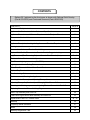
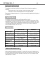
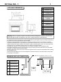
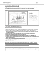
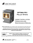
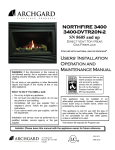
Optima 32 - 1
Gas Fired Vented Room
Heater (Direct Vent)
(SERIAL #3940 AND UP)
For use with Natural Gas or Propane*
WARNING: If the information in this manual is not
followed exactly, fire or explosion may result
causing property damage, personal injury or loss
of life.
Do not store or use gasoline or other flammable
vapors and liquids in the vicinity of this or any
other appliance.
USERS’ INSTALLATION
OPERATION AND
MAINTENANCE MANUAL
WHAT TO DO IF YOU SMELL GAS:
∗ Do not try to light any appliance.
∗ Do not touch any electrical switch; do not use
any phone in your building.
∗ Immediately call your gas supplier from a
neighbor’s phone. Follow the gas supplier’s
instructions.
∗ If you cannot reach your gas supplier, call the
fire department.
Installation and service must be performed by a
qualified installer, service agency or the gas
supplier.
This appliance may be installed in an
aftermarket permanently located,
manufactured home (USA only) or mobile
home, where not prohibited by local codes.
This appliance is only for use with the type
of gas indicated on the rating plate. This
appliance is not convertible for use with
other gases, unless a certified kit is used.
*Conversion kit required for Propane use
Installer: Please leave this manual with the appliance owner for future reference
7116 Beatty Dr
Mission, BC V2V 6B4
Canada
200-0165
Feb 2007
INTRODUCTION
Congratulations on choosing an Archgard Gas Fireplace!
The Optima 32-1 Direct Vent Insert is one of the most advanced Direct Vent Insert heater
available today. It is solidly designed using the latest technology and manufactured to the
highest quality. It is our aim to provide you with an appliance for many trouble-free years of
reliable service.
Some of the many features of your Optima 32-1 Direct Vent Insert are:
Heater Classification
High Efficiency
Adjustable Fan Speed
Adjustable Flame
Solid Construction
Optional Accessories
Millivolt Control System.
The Optima 32-1 is classified as a heating appliance. Therefore, it
uses Direct Vent safety technology and it is suitable for continuously
operated zone heating.
The Optima 32-1 has one of the highest efficiencies of any Direct
Vent gas insert, which means that it is less expensive to operate.
Each Optima 32-1 insert comes complete with a heat activated
circulation fan with a fully adjustable speed control.
The flame aesthetics and heat output can be adjusted to suit the
owner’s liking and heating needs.
The Optima 32-1 is mainly constructed of 16 and 18 gauge
galvanized and aluminized coated steel for long life and durability.
Check with your Authorized Archgard Dealer for a full complement of
decorative accessories to suit your home’s décor and your tastes.
Some of the accessories available are: 24K Gold Overlay (for the flat
window), a variety of surrounds (faceplates) with gold, black or
pewter trims and an overlay bay window that simply attaches to the
front of your fireplace while leaving the flat glass door in place.
The Optima 32-1 uses a gas control valve that is ready for an
optional wall thermostat, or a hand-held “wireless” remote control.
Please read this manual carefully prior to installation and operation of the appliance.
Proper installation, operation and maintenance of the appliance will provide you with
many years of enjoyment.
We recommend you record the following information:
Fireplace Model Number:
OPTIMA 32-1
Serial Number:
Date of Installation:
Type of Gas Used by the Fireplace:
Dealer’s Name & Address:
Dealer’s Phone Number:
Natural Gas
Propane
CONTENTS
•
Optima 32-1 pictured on the front cover is shown with Optional Gold Overlay
(Part # GO-32/35) and Contoured Surround (Part # ESK-32R)
CONTENTS
PAGE #
Caution and Safety Instructions
5
Appliance Certification, Installation Codes and Specifications
6
Appliance Dimensions and Minimum Requirements for Fireplace Dimensions
7
Clearance to Combustibles
8
Gas Connections
9
Appliance Description, Leveling the Appliance and Electrical Requirements
10
Venting Instructions
11 - 12
Surround Installation and Rocker Switch Wiring
13
Optional Wall Switch, Thermostat or Remote Control. Suggested wiring.
14
Log Placement (FiberFlame Log Set) and Ceramic Brick Panels (Liner)
15 - 19
Final Installation Check and Initial Operation
20
First Fire and Lighting Instructions (CAUTION)
21
Lighting Instruction on Rating Plate
22
Glass Door Removal / If Your Glass Should Break
23
Optional Bay Door Installation Instructions
24
Troubleshooting Guide
25 - 26
Maintenance and Cleaning the Appliance
27
Servicing Under Warranty and Adjusting Primary Air
28
Adjusting Primary Air (Continued) and Changing Main Burner Orifice
29
Checking Inlet/Outlet gas pressures, Adjusting Pilot and Convertible Pilot Orifice
30
Replacing Convection Blower & Wiring Diagram
31
Valve Tray Assembly and Parts List
32
FiberFlame Logs & Burner Bed Assembly and Parts List
33
Replacement Parts List - General Parts
34 - 35
Warranty
36
Frequently Asked Questions
37
Notes
38
Warranty Registration Card
40
Optima 32 - 1
5
CAUTION
FOR YOUR SAFETY - Do not install or operate your Archgard Optima 32-1 Direct Vent Gas
Insert without reading and understanding this manual. Any installation or operational deviation
from this instruction manual voids the Archgard Industries Warranty and may prove hazardous.
This appliance must be installed by a qualified gas installer and the installation must conform to
the installation codes.
Provide adequate clearance around air openings of the appliance.
Never obstruct front openings.
Provide adequate clearances for proper operation and servicing of the appliance.
This appliance must be properly connected to an approved venting system and must not be
connected to a chimney flue serving a separate solid fuel burning appliance.
SAFETY
Due to high temperatures, the appliance should be located out of traffic and away from furniture
and draperies.
Children and adults should be alerted to the hazards of high surface temperature and stay
away to avoid burns or clothing ignition.
Young children should be carefully supervised when they are in the same room as the
appliance.
Clothing or other flammable material should not be placed on or near the appliance.
Do not operate with cracked or broken glass. Be careful not to strike or slam the glass.
Any safety screen or guard removed for servicing an appliance must be replaced prior to
operating.
Installation and Repair should be done by a qualified service person. The appliance should be
inspected before use and at least annually by a professional service person. More frequent
cleaning may be required due to excessive lint from carpeting, bedding materials, et cetera. It is
imperative that the control compartments, burners and circulating air passageways of the
appliance are kept clean.
Do not use this appliance if any part has been under water. Immediately call a qualified service
technician to inspect the appliance and to replace any part of the control system and any gas
control which has been under water.
Optima 32 - 1
6
APPLIANCE CERTIFICATION
This appliance is tested and certified to the following USA and Canadian gas appliance
standards.
- ANSI Z21.88b-2003 / CSA 2.33b-2003, Vented Gas Fireplace Heaters,
- CAN/CGA-2.17-M91, Gas-Fired Appliances for Use at High Altitudes
Please contact Archgard Industries Ltd., if you have any questions regarding the certification of
this appliance.
INSTALLATION CODES
This appliance must be installed by a qualified gas appliance installer.
The installation must conform with the local codes or, in the absence of local codes, with the
current National Fuel Gas Code, ANSI Z223.1/ NFPA 54, in the US or Installation Code, CAN/
CGA-B149, in Canada. Electrical connections and grounding must conform with local code, or
current National Electrical code, ANSI/NFPA No. 70-1987, in the US and in Canada, the
current Canadian Electrical Code, CSA C22.1.
SPECIFICATIONS
Natural Gas (NG)
Propane (LP)
1.6 - 3.5 in. w.c. (0.4 - 0.9 kPa)
6.3 - 10.0 in. w.c. (1.6 - 2.5 kPa)
Min. Supply Pressure
Max. Supply Pressure
4.5 in. w.c. (1.2 kPa)
14.0 in. w.c. (3.5 kPa)
11.0 in. w.c. (2.8 kPa)
14.0 in. w.c. (3.5 kPa)
Orifice Size
#35 DMS (2.8 mm dia)
#51 DMS (1.72 mm dia)
Nominal Input Rating
23,000 - 34,000 BTU/hr
(6.7 - 9.8kW)
26,000 - 34,000 BTU/hr
(7.7 -9.8kW)
120 volt (a/c), 2.0 amp, 60 Hz.
120 volt (a/c), 2.0 amp, 60 Hz.
Milli-Volt (Quick Drop-out), Hi/Lo
Milli-Volt (Quick Drop-out), Hi/Lo
0 - 4,500 ft. (0 - 1372 M)
0 - 4,500 ft. (0 - 1372 M)
50% OPEN
FULLY OPEN
Manifold Pressure
Electrical Rating
Gas Control
Altitude
Primary Air Opening
HIGH ALTITUDE INSTALLATION
When installing this appliance beyond 4500 ft. (1372 M) above sea level, the appliance must
be properly de-rated and installed according to local codes, in the absence of local codes, with
the current National Fuel Gas Code, ANSI Z223.1/ NFPA 54, in the US or Installation Code,
CAN/CGA-B149, in Canada.
Optima 32 - 1
7
APPLIANCE DIMENSIONS
DIMENSIONS
A
25-5/8” (651 mm)
B
16” (406 mm)
C
14” (356 mm)
D
14-1/8” (359 mm)
DSK-32 or ESK-32
(STANDARD SURROUND)
E
41-1/2” (1054 mm)
F
27-3/4” (705 mm)
LSK-32 (LARGE FLAT
SURROUND)
E
47-1/2” (1207 mm)
F
30-3/4” (7457 mm)
G
19-7/8” (505 mm)
H
3-3/4” (93 mm)
I
1-1/4” (32 mm)
Warning: Failure to position the parts in accordance with these diagrams or failure to use only parts
specifically approved with this appliance may result in property damage or personal injury.
The installer must mechanically attach the marking supplied with the gas fireplace insert to the inside of the firebox of
the fireplace into which the gas fireplace insert is installed.
Cutting of any sheet-metal parts of the fireplace, in which the gas fireplace insert is to be installed, is prohibited.
If the factory-built fireplace has no gas access hole (s) provided, an access hole of 1 1/2” (37.5 mm) or less may be
drilled through the lower sides or bottom of the firebox in a proper workmanship-like manner. This access hole must
be plugged with non-combustible insulation after the gas supply line has been installed.
The fireplace flue damper can be fully blocked open or removed for installation of the gas fireplace insert.
The fireplace and fireplace chimney must be clean and in good working order and constructed of non-combustible
materials. The chimney cleanouts must fit properly.
Refractory, glass doors, screen rails, screen mesh and log grates can be removed from the fireplace before installing
the gas fireplace insert.
Smoke shelves and baffles may be removed if attached by mechanical fasteners. Trim panels shall not seal ventilation openings in the fireplace.
MINIMUM FIREPLACE DIMENSIONS
Min flue size required 4” (102) x 7” (178)
DIMENSIONS
J
20” (508 mm)
K
15-3/4” (400 mm)
L
16-1/2” (419 mm)
M
27” (685 mm)
K
SIDE
VIEW
J
L
M
TOP VIEW
Optima 32 - 1
8
CLEARANCES TO COMBUSTIBLES
WARNING: Failure to position the parts in accordance with these diagrams or failure to use
only parts specifically approved with this appliance may result in property damage or personal
injury or loss of life.
CAUTION: This appliance is designed for used in any masonry or factory built wood burning
fireplace. It cannot be enclosed by combustible material and used as a built-in gas fireplace.
Combustible mantle allow in
shaded area. Mantle extension
maybe increased 1” (25 mm) for
each additional 1” (25 mm)
increase in clearance height.
Example: If using a 5” (127 mm)
reduce minimum height to
36” (914 mm).
If using a 4” (100 mm) reduce
minimum height to 35” (889 mm)
SIDE VIEW
6” (152 mm)
Note:
If existing wood fireplace
hearth protection is
removed it must be
replaced by a non
combustible hearth
protection extending
16” (406 mm) from the
front of the
fireplace insert.
Note: With bay window
attached clearances
remain the same.
Minimum Height
From Bottom of
Appliance: 37”
(940 mm) with a
6” (152 mm) mantel.
TOP VIEW
Minimum 1” (25 mm)
clearance is required from the
faceplate (fireplace surround)
to a sidewall or mantle
support. See APPLIANCE
DIMENSIONS for surround
sizes.
1” (25 mm)
1” (25 mm)
Clearances to Faceplate
Sidewalls or Mantle Supports
Optima 32 - 1
9
GAS CONNECTIONS
Before connecting the appliance to the gas supply line, double check that the appliance you
have purchased is designed for the gas type you are using. The gas type markings are located
on the certification label and also on the appliance’s gas valve.
Adequate clearance for proper installation and checking of the gas connections must be
provided. All gas connections must be checked for gas leaks.
Have your gas supplier or a qualified gas fitter run a gas supply line into the fireplace.
The line must be properly sized and fitted according to the installation codes. Immediately up
stream of the supply connection, the fitter shall provide an accessible manual shut-off valve
and a 1/8 (3 mm) NPT plugged tapping accessible for connection to a test gauge. When
connecting the supply line to the gas valve, the installer shall brace the gas valve to ensure that
gas valve is not moved from its bracket. If the valve is not braced when the supply line is
connected, the valve may be moved and cause a “break” in the main burner supply line. Such
damage is not covered by the manufacturer’s warranty.
CAUTION: The appliance and its individual shutoff valve must be disconnected from the gas
supply piping system during any pressure-testing of that system at test pressures in excess of
1/2 psig (3.5 kPa). The appliance must be isolated from the gas supply piping system by
closing its individual manual shutoff valve during any pressure-testing of the gas supply piping
system at test pressures equal to or less than 1/2 psig (3.5 kPa). Failure to do so will damage
the appliance’s gas valve. Such damage is not covered by the manufacturer’s warranty.
Natural Gas Pressure Settings:
The inlet supply or line pressure must be a minimum of 4.5” wc (1.1 kPa) and a maximum of 8”
wc (2 kPa). The orifice is a #35 DMS (2.79 mm) drill size.
ELEVATION
INPUT RATING
0-4500 ft (0-1372 M)
34,000 BTU/hr (9.8 kW)
4500 ft (1372 M) and above.
34,000 BTU/hr (9.8 kW) less 4% per 1000 ft. (305 M)
Please contact your local utility or distributor for the appropriate orifice size you require.
Propane Pressure Settings:
The inlet supply or line pressure must be a minimum of 11” wc (2.8 kPa) and a maximum of 14”
wc (3.5 kPa). The orifice is a #50 DMS (1.79 mm) drill size.
ELEVATION
INPUT RATING
0-4500 ft. (0-1372 M)
34,000 BTU/hr (9.8 kW)
4500 ft. (1372 M) and above.
34,000 BTU/hr (9.8 kW) less 4% per 1000 ft. (305 M)
Please contact your local utility or distributor for the appropriate orifice size you require
NOTE: THE INPUT RATING SHOULD ALWAYS BE CHECKED WHEN FIRST RUNNING
THIS APPLIANCE. To do this, reduce the background flow rate, time the meter, light the
fireplace and take another reading after 15 minutes of operation. Check with your gas supplier
for the gas BTU content at your elevation. Input is the rate of flow multiplied by the heating
value of the gas (cubic feet/hour x BTU per cubic feet). Adjust the manifold pressure so that
the unit does not operate above the rated input.
Optima 32 - 1
10
APPLIANCE DESCRIPTION
TOP VIEW
On/Off
Rocker
Switch
Gas Inlet side
and power cord
outlet
Exhaust
Fresh Air Intake
FRONT VIEW
Surround
“Faceplate”
Ceramic Brick
“panel” liner
FiberFlame Log
Set & Burner
System
Top “grill”
louver
Ceramic
Glass with
standard
black arch
door frame
Bottom
“grill” louver
LEVELING THE OPTIMA 32-1 DIRECT VENT INSERT
Before placing the appliance into the fireplace, check the hearth of the fireplace to see if it is
level with the front of the fireplace. If it is not, measure the depth of the hearth. Loosen the
three screws of the leveling “L” bracket at the back of the appliance. Lower it to the
measurement obtained and tighten the screws.
ELECTRICAL CONNECTIONS
The Optima 32-1 comes complete with a temperature activated fan and rheostat installed and
wired to a three-prong (grounding) plug for your protection against shock hazard and should be
plugged in directly into a properly grounded three-prong receptacle. Do not cut or remove the
grounding prong from this plug.
NOTE: This appliance, when installed, must be electrically grounded in accordance with local
codes or, in the absence of local codes, with the National Electrical Code, ANSI/NFPA 70, or
the Canadian Electrical code, CSA C22.1.
Optima 32 - 1
11
VENTING INSTRUCTIONS
WARNING: Operation of this heater when not connected to a properly installed and maintained venting system can result in carbon monoxide (CO) poisoning and possible death.
The appliance must not be connected to a chimney flue serving a separate solid fuel
burning appliance.
Caution: Only two 3” (76 mm) “FLEX-MASTER” Model GA gas flex vent liners (or approved equivalent)
and a vent terminal is approved for use with this appliance.
Approved vent terminals are:
Archgard terminal. Part # TK-40/32.
Simpsons Dura-Vent terminal. Part #980, 923GK (adaptor with flashing) or 991 (high wind cap)
NO OTHER VENTING SYSTEM OR COMPONENTS MAY BE USED. If you are using “Dura-Vent” vertical termination cap, follow the instructions provided with the “Dura-Vent” cap.
This appliance is designed to attach to two 3” (76 mm) co-linear aluminum flex gas liners running the full
length of the chimney. The flue length must be a minimum of 8’ (2.44 M) and a maximum of 35’ (10.6 M)
(The exhaust vent restrictor provided with this appliance must only be used by installing it in the
exhaust collar, before attaching the flex liner, on Natural gas units with vent heights to 20’ (6.1 M)
restrictor #1 20’ and above restrictor #2). Also refer to the following page for details. The minimum flue
size is 4” x7” (100 mm X 178 mm).
Masonry chimneys may take various contours which the flexible liner will accommodate, however, keep
the flexible liner as straight as possible, avoiding unnecessary bending but at all times keep a minimum of
3” (76 mm) inside bend radius.
The Air Intake Flex Liner must be connected to the inlet air collars of the termination cap and the appliance. The Exhaust Flex Liner must be connected to the exhaust collars of the termination cap and the
appliance. (DO NOT MIX-UP THESE CONNECTIONS).
The Air intake and Exhaust connections are marked on the gas appliance. See Fig. 1.
CAUTION: To ensure that the venting path is not accidentally obstructed or punctured, the
damper of the host fireplace must be permanently disabled by either complete removal of the
damper, or welding it in its “open” position. Temporarily disabling the damper with braces,
wedges, brackets, etc., is not allowed.
The Optima 32 showing the Exhaust and Fresh Air Intake locations.
These connections are labeled for you.
The Optima 32
Requires two
Flexible gas flue
liners
Flue Collar (inlet) 3” (76 mm) diameter
Flue Collar (outlet) 3” (76 mm) diameter
Fig 1.
Exhaust
Fresh Air Intake
Optima 32 - 1
12
VENTING INSTRUCTIONS TK-40/32
Instructions for use with Archgard vertical termination cap. Part # TK-40/32.
Install the termination cap being sure to provided sufficient space (around and on top) so as not
to impede the flow of air, both into and out of the cap. This cap is only to be used for non combustible installations. Do not recess into the top of the chimney.
Mark each end of one liner with “Air Intake”.
Mark each end of the second liner with “Exhaust”.
Pull the liner through the chimney.
Install the flashing. Do Not bend or cut the flashing in any way.
Seal and attach the liner marked “Air Intake” to the vent terminal pipe marked “Air Intake” with the collar
clamp provided.
6. Seal and attach the liner marked “Exhaust” to the vent terminal pipe marked “Exhaust” with the collar clamp
provided.
7. Seal and attach the end of the flex marked “Air Intake” to the collar marked “Air Intake” on the appliance
with the collar clamp provided with the unit.
8. Install the exhaust vent restrictor provided with the unit on Natural Gas appliances with 20’ (6.1 M) and
above vent height installations ONLY Seal and attach the end of the flex marked “Exhaust” to the collar
marked “Exhaust” on the appliance with the collar clamp provided with the unit..
10. Caulk all joints as usual.
1.
2.
3.
4.
5.
NOTE: The vertical termination cap must be sealed to the liner with suitable high temperature sealant and with the
hose clamps fasteners provided. The liners must form a complete connection from the appliance flue collars to the
vertical termination cap.
Note Vent restrictor # 1 is the
item with the notch (restrictor #
2 shown in picture
Vertical Termination
cap Part # TK-40/32
Exhaust
Collar
Air Intake
Collar
Min. vent height 8’ (2.44 M)
Max. vent height 35’ (10.6 M)
Fresh Air
Intake
3” (76 mm)
Flex Liner
Front view of
DV Insert
Exhaust
Place Vent Restrictor
in the position shown
(on the exhaust collar
before attaching the
Flex Liner) ONLY
when operating with
NATURAL GAS with a
VENT OF up to
20’ (6.1 m) restrictor
#1 AND 20’ (6.1 m)
ABOVE restrictor #2
The minimum flue (chimney) size required to run the two 3” (76 mm) is 4” x 7” (100 mm X 178 mm)
Optima 32 - 1
13
SURROUND INSTALLATION
Make sure the gas and electrical lines are properly connected to the appliance. Slide the unit
into the fireplace and slide the excess flue liner material back onto the chimney. Before the appliance is fully recessed into the fireplace, attach the surround onto the appliance. The return
flange on the side of the surround fits on the inside of the mounting rails on the appliance.
Attach the surround to the appliance at the locations shown with the four (4) screws
provided. Then finish with the wiring connection to the on/off switch on the side of the trim.
Now fully “seat” the unit into its final position.
SCREW
LOCATIONS
CAUTION:
Only Trim kit (s) supplied by
the manufacturer shall be
used in the installation of this
appliance.
Trim Instructions for the Surround
for the DSK, ESK & LSK Surround
1. Using the trim clips provided, join the left side trim (which has a notch cut for rocker switch)
to the top trim as shown in (Fig.1). Repeat with the right side trim.
2. Peel the backing from the sticky tape, then slip the assembled trim over the surround.
3. Locate the rocker (on/off) switch (with the ON side up) and push it in the notch located on the
left side.
4. Remove the coiled wires from the left side of the firebox and connect it to the rocker switch
tabs.
5. The switch wires have crimped connections that are factory installed. Simply connect the
crimped connections to the on/off (rocker) switch located on the surround.
Fig. 2
Fresh Air Intake
Fig. 1
Gas Inlet side
and power cord
outlet
Exhaust
On/Off
Rocker
Switch
Optima 32 - 1
14
OPTIONAL WALL SWITCH OR THERMOSTAT
If a wall-mounted switch or a wall-mounted thermostat is desired, Archgard recommends that
the device be wired as shown in Fig 1. This will allow the original on/off rocker switch to be
used in case the device that is mounted to the wall becomes inoperable.
Note: Archgard Industries does not manufacture or sell any wall switch or wall thermostat, and
will not extend warranty to them.
Thermostat / wall switch wire table
Recommended Maximum Lead Length
for two wires.
Wire Size
Max. Length
14 GA.
50 Ft. (15.24 M)
16 GA.
32 Ft. (9.75 M)
18 GA.
20 Ft. (6.9 M)
20 GA.
12 Ft. (3.65 M)
22 GA.
9 Ft. (2.74 M)
VALVE CONNECTION for MILLIVOLT VALVE
Fig. 1
C
B
OPTIONAL REMOTE,
WALL SWITCH, OR WALL
THERMOSTAT
D
ON/OFF SWITCH
A
WIRE TO
PIEZO
(SPARKER)
PILOT ASSEMBLY
A
ELECTRODE
B
THERMOPILE
C
PILOT CAP
D
THERMOCOUPLE
THERMOCOUPLE LEAD
SUPPLY TUBE
Optima 32 - 1
15
LOG PLACEMENT
The Archgard “FiberFlame Technology Burner System” of ceramic logs is designed to give a
realistic fire package, and created to look the same as the day they were originally installed.
Care must be given when first installing the logs, and if removed for servicing, as they can be
damaged or broken if not handled properly.
After opening the log set package, inspect the logs to ensure that no damage has occurred inside the package. Please report any damage immediately to your Authorized Archgard Dealer.
Gas and vent connection must be made before installing the logs on the “FiberFlame” bed.
NOTE: Improper placement of logs may cause sooting on the internal parts and glass, and will
not be covered under warranty. Do not use broken or damaged logs.
WARNING:
Failure to position the parts in accordance with these diagrams or failure to use only parts
specifically approved with this appliance may result in property damage or personal injury.
The ember bed is pre-formed to accept the first four “base” logs. Locate the first four base logs, and place
them on their perspective locations. Refer to the pictured instructions on the following pages that will show
how to place all seven (7) logs. The bottom of each log has a 2 digit code that can be used as a reference
to help locate the correct log.
IMPORTANT: DO NOT PLACE ANY LOGS OVERTOP OF THE BURNER “PORTS”.
FiberFlame Burner Bed and Rear Log Rest
Rear log rest
Pre-formed log locations
NOTE:
Installing the “FiberFlame” Ceramic logs in any other position other than shown will result in flame
impingement causing sooting of the logs, brick liner and ceramic glass viewing area.
Optima 32 - 1
16
LOG PLACEMENT... Continued
Step 1. Locate Log with 12 stamped on the bottom and place it on the log rest as shown.
LOG 12
Step 2. Locate Log with 80 stamped on the bottom and place it on the log rest as shown.
LOG 80
Optima 32 - 1
17
LOG PLACEMENT... Continued
Step 3. Locate Log with 74 stamped on the bottom and place it on the ember bed as shown.
LOG 74
Step 4. Locate Log with 69 stamped on the bottom and place it on the ember bed as shown.
LOG 69
Optima 32 - 1
18
LOG PLACEMENT... Continued
Step 5. Locate Log with 82 stamped on the bottom and place as shown.
LOG 82
Step 6. Locate Log with 83 stamped on the bottom and place as shown.
LOG 83
Optima 32 - 1
19
LOG PLACEMENT... Continued
Step 7. Locate Log 13 and place it as shown.
LOG 13
CERAMIC BRICK PANELS
The Optima 32-1 comes with a set of Ceramic Brick Panels. They are factory installed for your
convenience, therefore no adjustments should be made. If you find any damage to the Ceramic Brick Panels please contact your Authorized Archgard Dealer who sold you this appliance to order replacements.
Optima 32 - 1
20
FINAL INSTALLATION CHECK
Each Archgard Gas Fireplace is checked and tested at the factory prior to being packaged and
shipped to our dealers, and finally installed in your home. Archgard recommends that before
leaving this unit with the customer, the installer must ensure that the appliance is firing
correctly and that the electrical system is in working order. This will include:
1. Pre-form Leak tests of supply line, gas control valve, supply line from gas control valve and
pilot assembly.
2. Clocking the appliance to ensure the correct firing rate (see page 9 of this manual).
3. If required, adjusting the primary air to burner to ensure that the flame does not carbon or
soot. (see page 28 of this manual) .
4. Check for proper operation including correct drafting.
5. The FAN system should be turned ON for a minimum of 10-15 minutes to ensure that the
fan, rheostat and fan sensor are all working correctly. After the system has been checked,
and confirmed that the fan components are in working order, turn the fan system OFF and
refer to the instructions for FIRST FIRE located in this manual.
As a reminder, a TAG is attached to all of our gas fireplaces. This TAG is located at the gas
control valve. See Fig 1.
Fig 1.
ARCHGARD INDUSTRIES LTD.
*** INSTALLER ***
IMPORTANT NOTICE
ALL GAS AND ELECTRICAL CONNECTIONS
** MUST ** BE CHECKED AND TESTED AT
TIME OF INSTALLATION.
Any alteration to the product that causes carboning or sooting that results in any
damage or requires cleaning is not the responsibility of the manufacturer.
INITIAL OPERATION
1. Check that the appliance is properly vented and connected to the gas supply.
2. Check that the logs and branches are properly placed.
3. Check that all external parts, such as grills, door and faceplate are properly attached and
fastened.
4. Do not operate this appliance with broken, cracked glass doors or without the door (s) in its
correct (and latched) position. Do not abuse the glass by either striking or slamming shut.
5. Check that there are no finger prints left on gold surfaces or glass panels as high
temperature can bake these prints permanently.
Optima 32 - 1
21
FIRST FIRE
When operated for the first few times, the appliance will emit some odor and fumes. This is due
to the heat from the appliance evaporating the oils and solvents used in fabricating the
appliance. Close off the room to the rest of the house and open all windows. Keep the room
well ventilated as smoke alarm may sound. Run the appliance for at least 6 hours at maximum
setting with blower set to “OFF” to allow paint to cure (after the installer has checked to ensure
the fan is operational). Smoke and fumes caused by the curing process may cause discomfort
to some individuals.
LIGHTING INSTRUCTIONS - CAUTION
WARNING : If you do not follow these instructions exactly, a fire or explosion may
result, causing property damage, personal injury or loss of life. Do not
operate the appliance with the glass front removed, cracked or broken.
Replacement of broken glass should be done by a licensed or qualified
service person.
This appliance has a pilot which must be ignited using the sparker located next to the appliance
valve controls. When lighting the pilot, follow the start-up procedures exactly.
See next page or rating plate for complete lighting instructions.
1. BEFORE LIGHTING, smell all around the appliance area for gas. Be sure to smell next to
the floor, because some gases are heavier than air and will settle on the floor.
2. IF YOU SMELL GAS, follow the instructions on the front cover of this manual.
3. Use only your hand to push in or turn the gas control knob. Never use tools. If the knob will
not push in or turn by hand, don’t try to repair it. Call a qualified service technician. Force or
attempted repair of gas control knob may result in a fire or explosion.
4. Do not use this appliance if any part has been under water. Immediately call a qualified
service technician to inspect the appliance and to replace any part of the control system
and any gas control which has been under water.
Optima 32 - 1
22
LIGHTING INSTRUCTIONS ON RATING PLATE
FOR YOUR SAFETY READ BEFORE LIGHTING
WARNING: If you do not follow these instructions exactly, a fire of explosion may result causing
property damage, personal injury or loss of life.
A. This appliance has a pilot which must be lighted by a spark
ignitor. When lighting the pilot follow these instructions
exactly.
B. BEFORE LIGHTING smell all around the appliance area
for gas. Be sure to smell next to the floor because some
gas is heavier than air and will settle on the floor.
• If you cannot reach your gas supplier, call the fire
department.
C. Use only your hand to push in or turn the gas control knob.
Never use tools. If the knob will not push in or turn by hand
don’t try to repair it, call a qualified service technician.
Forced or attempted repair may result in a fire or
explosion.
WHAT TO DO IF YOU SMELL GAS
• Do not try to light any appliance.
D. Do not use this appliance if any part has been under water.
• Do not touch any electrical switch; do not use any phone in
Immediately call a qualified service technician to inspect
your building.
the appliance and to replace any part of the control system
• Immediately call your gas supplier from a neighbor’s
and any gas control which has been under water.
phone. Follow the gas supplier’s instructions.
LIGHTING INSTRUCTIONS
1. STOP! Read the safety information above on this label.
2. Set the remote switch to “OFF”. Set the thermostat to the
lowest setting. (Only if your appliance is equipped with
these devices.)
3. Turn off all electric power to the appliance.
4. Open lower louvers or access door.
3. Press slightly and turn the control knob clockwise 3 to the
“OFF” position.
4. Wait 5 minutes to clear out any gas. Then smell for gas,
including near the floor. If you smell gas, STOP! and follow
instruction “B” above.
5. Find pilot. It is located between the logs near the center
behind the burner.
6. Press slightly and turn control knob counterclockwise 4 to
“PILOT”. Depress knob and light pilot by repeatedly
pressing the sparker. Once flame is established, hold knob
Flame Adjustment Knob
depressed for approximately 30 seconds. Release knob. If
pilot should go out, repeat steps 3 to 5.
• If the knob does not pop up when released, stop and
immediately call your service technician or gas supplier.
• If the pilot will not stay lit after serveral tries, turn the gas
control knob to “OFF” and call your service technician or
gas supplier.
7. If the appliance has a manual valve, turn gas control knob
counterclockwise 4 to the desired heat setting from “LO”
to “HI”. If the appliance has an automatic valve, turn gas
control knob counterclockwise 4 to “ON” and set the flame
adjustment knob to the desired heat setting from “LO” to
“HI”.
8. Set the remote switch to “ON”. Set the thermostat to the
desired setting. (Only if your appliance is equipped with
these devices.)
9. Turn on all electric power to the appliance.
10. Close louver or access door.
Sparker
Sparker
Control Knob
Automatic Valve
Control Knob
Manual Valve
Pilot
TO TURN OFF GAS TO APPLIANCE
1. Set the thermostat to the lowest setting and turn the remote 3. Open lower louvers or access door.
switch to “OFF”.
4. Press slightly and turn control knob clockwise 3 to “OFF”.
2. Turn off all electric power to the appliance if service is to be
Do not force.
performed.
303-0001 28MAY01
5. Close lower louvers or access door.
Optima 32 - 1
23
GLASS DOOR REMOVAL
WARNING: Do not operate appliance with the glass front cracked or broken. Replacement of
the glass should be done by a licensed or qualified service person.
CAUTION: Do not attempt to remove the glass door when the appliance is hot.
1.
Remove the TOP louver by pulling the entire louver assembly towards you.
2.
Open up the BOTTOM louver assembly to expose the control valve.
3.
Locate the 2 buckle latches under the glass door frame (Fig.1) and pull down the lever on
the back of the latches to release them.
4.
Unhook the latches from the bottom of the door and swing the bottom of the door towards
you then lift up on the whole door to unhook the top of the door. Carefully remove the
door and put it away at a safe location where it cannot be scratched or damaged.
Replacing the Glass Door
The reverse procedure of Removing the Glass Door.
Fig. 1.
LOCATING TABS
(UPPER LOUVERS
REMOVED)
DOOR LATCHES
(SHOWN OPEN)
IF YOUR GLASS BREAKS
In the event your glass cracks or breaks, Archgard recommends that a new door assembly be
ordered to replace the original door.
•
•
Remove door as per the instructions above.
Replace with new door assemblies.
NOTE: the NEW door will emit some odor when the appliance is re-lit and the odor will dissipate
after the gasket material within the door has cured.
Warning : Do not use substitute glazing materials
Optima 32 - 1
24
OPTIONAL BAY DOOR INSTALLATION
WARNING: THE OPTIONAL BAY DOOR BBAY-32 IS A DECORATIVE OPTION ONLY AND IS
MANUFACTURED WITH TEMPERED GLASS. THIS UNIT MUST NOT BE OPERATED WITHOUT THE FLAT CERAMIC GLASS DOOR SECURED IN PLACE, BEHIND IT.
After opening the bay door package, inspect the door to ensure that no damage has occurred
inside the package. Please report any damage immediately to your Authorized Archgard Dealer.
Installation of the Bay Door Option does not change any clearances stated on the rating
plate/ or Installation Operation and Maintenance Manual accompanying the appliance.
NOTE: Ensure that the Heater is turned off and cool.
To install this Bay Door Accessory and Knob Extension Kit use the following instructions:
1
2
3
4
5
6
7
Remove the upper grilles by pulling the assembly forward.
Remove the lower grilles by removing the four hex head mounting screws that secure the
brass hinges to the unit.
Discard the Upper and lower grilles (they are not required for Bay door installation).
Install the Hi/Low, On/Off and sparker extension knobs onto the corresponding knobs on the
valve.
Move the Bay Door over the front of the insert, line up the slots in the upper area slightly
above the corresponding tabs at the front top of the firebox, and push the assembly down.
Parts supplied with the kit: BBAY 32 door assembly,
308-0094 Hi/Lo Extension Knob
308-0095 On/Off Extension Knob
308-0096 Piezo Extension Knob
The lower (center) hinges down for control access.
CAUTION:
Only Trim kit (s) supplied by the manufacturer shall be used in the installation of this appliance.
Optima 32 - 1
25
TROUBLESHOOTING
Please check to make sure the instructions are followed exactly before attempting
troubleshooting of the appliance.
WARNING: Troubleshooting and servicing of gas and electrical devices of the
appliance should only be conducted by a qualified service technician.
SYMPTOM
ACTION
Pilot will not light after
pressing the sparker many
times.
1. When lighting the appliance for the first time after installation or after
servicing, there is air in the gas line. It takes a while for all the air to
purge out of the pilot before gas can reach the pilot and ignite.
Remove the glass door and try lighting the pilot many times to purge
the air.
2. Check to make sure the gas supply to the appliance is turned on and
there is adequate gas supply pressure to the appliance.
3. Check for sparks between the spark electrode and the pilot head when
the sparker is pressed. If there are no sparks,
a. Check for broken or poor connection from the sparker to the
electrode.
b. Check for the spark shorting or arcing at other locations.
c. Check for defective sparker.
d. Check for defective spark electrode.
4. With the door removed, try lighting the pilot with a match.
a. If air is blowing on the flame of the match, hold the control knob in
at the ‘PILOT’ setting until all the air is purged out of the line.
b. If there is no gas or air coming out of the pilot and there is gas
pressure to the appliance, the pilot orifice may be blocked or the
gas valve may be defective.
Pilot will not remain on after
being lit.
1. Press the control knob all the way in (at the “pilot” indicator).
2. Hold the control knob in for a longer period of time.
3. If you are trying to re-light the pilot immediately after you have shut-off
the pilot, you have to wait 5 minutes for the valve to reset. (safety system built into the valve)
4. Check to see if the pilot flame is large enough to reach and surround
the thermocouple. If the flame is too small, check for correct gas
supply pressure. If pressure is good, adjust the pilot flame size with
the adjustment screw on the valve. If the flame cannot be adjusted,
there might be some debris obstructing the pilot orifice, or a wrong
size pilot orifice.
5. Check for poor connection of the thermocouple to the valve.
6. Check for proper millivolts of the thermocouple. The thermocouple
should generate at least 30 mV or it is defective.
7. Check for defective gas valve.
The main burner does not turn 1. Check to make sure the control knob is turned to the ‘ON’ position.
on with the pilot lit.
2. Allow enough time for the pilot to heat up the thermopile to generate
sufficient voltage to activate the valve.
Optima 32 - 1
26
TROUBLESHOOTING Cont...
SYMPTOM
ACTION
The main burner does not turn
on with the pilot lit. Cont...
3. Check to make sure the thermostat is set high enough to turn on the
appliance.
4. Check that the remote switch or the thermostat is turned on.
5. Check for weak pilot flame. If the flame is weak, check gas supply,
check pilot flame adjustment and check for blockage of pilot orifice.
6. Check all connections to the valve for tight electrical contact.
7. Check for 400-500 mV from the thermopile with the burner off and
200-250 mV with the burner on. If the voltages are lower, the
thermopile is defective.
8. Check for defective gas valve.
The main burner shuts off
when the appliance is warm.
1. This may be the normal operation of a wall thermostat installed to appliances.
2. Check for good pilot flames on the thermopile.
3. Check for good voltage from the thermopile.
4. Check for proper functioning of venting system (blocked)
5. If venting is suspected, refer to the venting section of this manual for
proper venting practices.
6. Check wire connections. Expansion from heat affects a loose connection.
Sooty deposits on the glass
door.
1. If the flame is yellow and lazy, check for lint etc. around primary air
shutter. Increase primary air by opening the primary air shutter if necessary.
2. Check for proper placement of the logs and branches. Ensure logs
and burner are clean. See that section in the instruction manual.
3. Check for proper venting and blockage of the vent termination.
4. Check manifold pressure and clock input rating for over-firing.
Sharp blue flames with flames
lifting off the burner at the
ends.
1. Too much primary air. Reduce primary air by closing the primary air
shutter. During cold temperatures, some flame lifting may occur
during start-up.
Convection blower does not
turn on.
1. The convection fan is thermostatically controlled. It will only turn on
when the appliance is warmed-up. This may take up to 15 minutes
with the appliance on high.
2. Check for 120 VAC electrical supply to the appliance. (Is the cord
plugged in?)
3. Check for proper mounting of the thermal snap disc.
4. Check electrical connections.
5. Check for defective thermal snap disc.
6. Check for defective convection blower speed controller.
7. Check for defective convection blower.
Optima 32 - 1
27
MAINTENANCE
CAUTION:
Do not conduct maintenance on the appliance while it is operating or while it is still hot.
CLEANING THE APPLIANCE
The exterior painted surfaces, glass and gold trims may be cleaned with a soft, non-abrasive
cloth and water or a suitable, mild, non-abrasive cleaner.
Regularly:
•
•
•
•
Frequent cleaning of the ceramic glass is required. Archgard recommends using a good
quality “gas fireplace” glass cleaner that is available at any hearth retail location. DO NOT
CLEAN WHILE HOT.
Clean and remove any lint accumulations or debris from the grills and in any combustion
and convection air passage ways.
Keep the appliance area free from combustible materials, such as paper, wood, clothing,
gasoline and flammable solids, liquids and vapors.
Visually check the height and color of the burner and pilot flames.
Every 2 to 3 months:
•
•
•
Remove the glass door and clean the inside of the glass with a good quality “gas
fireplace” glass cleaner. DO NOT CLEAN WHILE HOT.
Carefully remove the logs and gently brush off any loose carbon deposits. This job is best
done outside the house, wearing a dust mask.The logs are very fragile, take care not to
break them. Do not wash logs with any liquid. While the logs are removed, check that
all burner openings are not obstructed and it is recommended you use a vacuum cleaner
to clean off any dust or lint.
After cleaning, the logs must be replaced as per the instructions in this manual.
Once a year, have a qualified service technician:
•
•
•
Completely inspect the appliance and the venting system, if the vent pipe or seal is found
to be defective, replace and or reseal (follow the instructions found in the installation
section)
Clean and remove any lint accumulations or debris in the firebox, on the burners, on the
pilot, at the primary air opening, on the convection air blower and in any combustion and
convection air passageways.
Check the safety system of the gas valve and the appliance.
WARNING : All parts removed or disturbed, including guards and grills, must be
properly replaced after maintenance. Service and repair must be
conducted by a qualified service person. If these instructions are not
followed, a fire or explosion may result, causing property damage,
personal injury or loss of life.
Optima 32 - 1
28
SERVICING UNDER WARRANTY
Before servicing, read the terms and conditions of the Archgard warranty at the back of the
manual. Contact the authorized Archgard dealer where you purchased the appliance from and
provide them with details of the problem, together with the initial installation information (from
the back of this manual).
WARNING: Servicing of this appliance must be conducted by a qualified service
technician. Improper servicing, adjustment or alteration of this appliance may
cause property damage, personal injury or loss of life. All servicing should be
conducted with the appliance cold. All replacement parts must be authorized by
Archgard for suitability.
ADJUSTING PRIMARY AIR
Note: the Shutter is set at the factory and normally only requires resetting at higher altitudes.
Caution: Wear gloves when adjusting the primary air with the appliance hot.
1.
2.
3.
4.
Open the lower grills.
Unscrew the 2 screws holding the control panel and remove the panel.
The primary air adjustment wing nut is located behind and to the left of the control valve.
Loosen the wing nut and slide the primary air shutter to the right to increase primary air
and to left to reduce primary air.
5. Tighten the wing nut after adjustment.
Control Panel
Fig. 1.
Two Screws
Air Shutter (side view)
ORIFICE CENTERING BRACKET
ORIFICE CAP
PRIMARY AIR SHUTTER
ELBOW FITTING
ADJUSTMENT WING NUT
DECREASE
INCREASE
Optima 32 - 1
29
ADJUSTING PRIMARY AIR
NOTE: Fig. 1. Is to give an example of what is a correct or incorrect flame pattern. It is not a
true representation of what the Optima 32-1 will look like in your home environment.
Fig.1
FLAMES...
The left side shows
correct adjustment. The
right side shows yellow
sooty flames requiring
increase in shutter opening or cleaning of shutter
area due to lint buildup.
CHANGING MAIN BURNER ORIFICE
1. Remove the glass door. Follow GLASS DOOR REMOVAL instructions within this manual.
2. Locate & slide the Primary Air Sleeve fully toward the left. This will allow the sleeve to
disconnect from the burner tube. Follow ADJUSTING PRIMARY AIR instructions within this
manual for reassembly.
3. Remove the logs from the FiberFlame bed. See LOG PLACEMENT for instructions.
4. Remove the two screws holding the log rest to remove it.
5. Unscrew the two mounting screws that are located at the back rear of the ember bed.
6. Carefully remove the ember bed by using your index fingers in the holes and carefully lift the
ember bed (burner) out.
7. Use a 1/2” (13 mm) wrench to remove the orifice cap.
8. Change the orifice cap to the fuel type desired. Use a small quantity of gas thread seal
compound. Do not overtighten.
9. Reverse steps 6 to 1.
WARNING: When replacing the ember bed using the two screws, you MUST not overtighten the screws. Leave the screws “FINGER-TIGHT” allowing the ember bed to “float”.
This is required for expansion & contraction of the ember bed.
THIS APPLIANCE IS EQUIPPED FOR NATURAL GAS. An additional CONVERSION kit is required to
convert for Propane use. To order the CONVERSION kit, please contact your Authorized Archgard
Dealer.
Optima 32 - 1
30
CHECKING INLET AND OUTLET GAS PRESSURE
1.
2.
3.
4.
5.
6.
7.
Open the lower grills.
The pressure test taps are located on the valve. The taps are located in the gas valve front
face. The inlet is marked ‘IN’ and the outlet is marked ‘OUT’. See Fig.1.
Loosen the set screw inside the tap with a ⅛” (3 mm) wide flat screw driver.
Connect a ¼” (6 mm) rubber tube to the tap post and a manometer.
Verify the readings obtained are within specs (as shown on the appliance rating plate)
Be sure to tighten the set screw inside the tap after you are finish taking pressure readings.
Check for leaks.
Fig.1.
CHECKING AND ADJUSTING PILOT
The pilot flame should have the characteristic as shown in the illustration below. The
flame should not have yellow tips but
should engulf the thermocouple and thermopile. It can be adjusted be turning the
screw marked “pilot” on the control valve.
Thermocouple
Electrode
Thermopile
Burner Ports
CONVERTIBLE PILOT ORIFICE
The pilot assembly is convertible to the type
of gas being used, simply unscrew the body
by using a 7/16” (11 mm) wrench turn a 1/4
open then push the small metal tab across to
the other side of the body and retighten. Call
your local Authorized Archgard Dealer to
purchase the correct fuel conversion kit
for your gas appliance.
7/16” (11 mm)
WRENCH
(HERE)
Optima 32 - 1
31
REPLACING CONVECTION BLOWER
Caution: Label all wires prior to disconnection when servicing controls. Wiring errors can
cause improper and dangerous operation. Verify proper operation after servicing.
This appliance, when installed, must be electrically grounded in accordance with local codes
or, in the absence of local codes, with the National Electrical Code, ANSI/NFPA 70, or the
Canadian Electrical code, CSA C22.1.
NOTES:
• Ensure that the main power and breaker system is turned OFF before removing the fan.
• Make sure the fireplace has been turned off and is cool to the touch.
• Mark all wires to be removed for proper reassembly.
• CAUTION: Wiring errors cause improper and dangerous operation.
1.
2.
3.
4.
5.
6.
7.
8.
Remove the glass door. Follow GLASS DOOR REMOVAL instructions within this manual.
Remove the FiberFlame log set. Follow LOG PLACEMENT instructions within this manual.
Remove the adjustment wing nut and slide the air shutter away from the orifice cap.
Follow ADJUSTING PRIMARY AIR instructions within this manual.
Remove the FiberFlame Ember Bed. Follow CHANGING MAIN BURNER ORIFICE
instructions within this manual.
Mark all wires to be removed for proper reassembly. CAUTION: Wiring errors cause
improper and dangerous operation.
The convection blower is located at the bottom of the appliance at the back. Remove the
three screws holding the blower.
Lift the blower out and disconnect the wires from the blower.
Reverse instructions after new fan is installed & tested.
SPEED
CONTROL
WIRING DIAGRAM
NEUTRAL
120 VAC
LINE
GROUND
LINE
NEUTRAL
GROUND
black
black
100ºF (38ºC) N.O.
THERMAL SNAP
SWITCH
white
black
CONVECTION BLOWER
white
green
To Fan Mount
(with star washer)
SPEED
CONTROL
110F (43ºC) N.O.
THERMAL SNAP
SWITCH
MO
CONVECTION BLOWER
Optima 32 - 1
32
VALVE TRAY ASSEMBLY
J
K
G
E
N
M
L
H
I
O
F
B
C
D
A
Item #
Item Description
Qty
Unit
A
308-0091 Valve HONEYWELL Hi/Low Natural Gas
1
EA
B
308-0101 Replacement Piezo (comes pre-mounted on valve)
1
EA
C
301-0000 Straight ⅜” (9.5 mm) Compression ⅜” MNPT
1
EA
D
301-0009 Tubing ⅜” (9.5 mm) Ø - Aluminum (Main Supply Tube)
5⅜
IN
E
301-0001 Elbow ⅜” (9.5 mm) Compression 90 Deg. ⅛” (3 mm) MNPT
1
EA
F
301-0068 Orifice (Main Burner Orifice) Drill to # 35 DMS (2.76 mm) for
Natural Gas / Drill to #51 for LP (Propane) Gas
1
EA
G
301-0061 Washer ⅜” (9.5 mm) SAE Grade 8, Flat
1
EA
H
739-0019 Pilot Assembly Box
1
EA
I
314-0127 Gasket Ceramic Paper
J
314-0127 Gasket Ceramic Paper
1
EA
K
308-0093 Pilot Assembly. Convertible NG/LP Base Mount. Includes the
items listed below……..
1
EA
L
Part # 308-0057 - Thermocouple
1
EA
M
Part # 308-0056 - Thermopile
1
EA
1
EA
1
EA
N
O
832-0112 Complete Valve Tray Assembly
Air Shutter
Optima 32 - 1
33
PARTS LIST - FiberFlame Logs and Burner Bed
Log 80
Log 12
Log 82
Log 83
Log 74
Log 13
Log 69
FiberFlame Burner Bed
Item #
Item Description
Qty
Unit
310-0080 FiberFlame Log 80
1
EA
310-0074 FiberFlame Log 74
1
EA
310-0069 FiberFlame Log 69
1
EA
310-0012 FiberFlame Log 12
1
EA
310-0013 FiberFlame Log 13
1
EA
310-0082 FiberFlame Log 82
1
EA
310-0083 FiberFlame Log 83
1
EA
839-0051 Burner Bed Assembly (Includes Ember Bed)
1
EA
Optima 32 - 1
34
REPLACEMENT PARTS LIST ARCHGARD OPTIMA 32-1
Item #
Item Description
Qty
Unit
200-0165 Owners Manual
1
EA
832-0005 Top Louver (grill) assembly (Metallic Black)
1
EA
832-0004 Bottom Louver (grill) assembly (Metallic Black)
1
EA
300-0030 Hinge Self Closing Brass
2
EA
800-0060 Air Shutter Assembly
1
EA
314-0131 Air Shutter Gasket
2
IN
800-0031 Wiring Harness assembly for On/Off Rocker Switch
1
EA
305-0019 On/Off Rocker Switch
1
EA
305-0012 Power Cord 8’ (2.43 M)
1
EA
305-0013 Fan - Speed Control (Rheostat)
1
EA
305-0038 Fan - Thermodisc (fan sensor) 1000 F. (380 Celsius)
1
EA
305-0024 Fan - Fan with motor and blades. 120VAC, 115V, 24 watt
1
EA
702-0047 Fan - Thermodisc mounting bracket
1
EA
702-0050 Fan - Heat Shield
1
EA
1
EA
311-0063 Ceramic Brick Liner - Right Side
1
EA
311-0064 Ceramic Brick Liner - Left Side
1
EA
311-0054 Ceramic Brick Liner - Rear
1
EA
702-0044 Brick Panel Clips
2
EA
Fan Components
Flat Glass Door
800-0032
Complete Replacement Door. Includes glass, gasket and
door frame
Ceramic Brick
Optima 32 - 1
35
REPLACEMENT PARTS LIST ARCHGARD OPTIMA 32-1
Item #
Item Description
Qty
Unit
Replacement parts for BBAY-32 Bay Door
300-0031
Magnet Pull
2
EA
307-0026
Glass, 6mm Tempered (Middle Piece)
1
EA
307-0027
Glass, 6mm Temp (Side Piece)
2
EA
308-0095
Knob Ext. ON/OFF
1
EA
308-0094
Knob Ext. HI/LOW
1
EA
308-0096
Knob Ext. Piezo
1
EA
314-0006
Gasket Flat
65
IN
Optional Gold Bay Window Strips (Full Set)
Includes top & bottom trim pieces
1
EA
Black Trim for ESK & DSK-32R surround
1
SET
Black Trim for LSK-32R surround
1
SET
Gold Trim for ESK & DSK-32R surround
1
SET
Gold Trim for LSK-32R surround
1
SET
Pewter Trim for ESK & DSK-32R surround
1
SET
Pewter Trim for LSK-32R surround
1
SET
GMDS-32/25/70
Optional Surround Trims
BEDTK-32
BLTK-32
GEDTK-32
GLTK-32
PEDTK-32
PLTK-32
ARCHGARD LIMITED WARRANTY
This Limited Warranty is made by ARCHGARD INDUSTRIES LTD., hereinafter referred to as “Archgard”. Archgard warrants to the
original purchaser of an Archgard gas burning fireplace (s) that the product will be free of defects in materials and workmanship under
normal use and service, for a “lifetime”.
INCLUSIONS: “LIFETIME LIMITED WARRANTY“
All heat exchangers, combustion chamber, burner tubes and pans.
Ceramic Fiber Logs and Ceramic Brick Panels against splitting or cracking.
Ceramic Glass against thermal breakage.
All 24 K gold trims and accessories against tarnishing.
All trim accessories against tarnishing and paint defects.
NOTE: Discoloration and some minor movement of certain parts are normal and are not a defect and therefore, not covered under
warranty.
The above will be covered “parts & labor” to the original purchaser for FIVE years and “parts” only thereafter from original date of purchase.
INCLUSIONS: “FIVE YEAR LIMITED WARRANTY”
Five year limited warranty on the “FiberFlame Technology Burner System.” Warranty will cover any defective burner and ceramic
ember bed if defect is deemed as original by the manufacturer.
The above will be covered “parts & labor” to the original purchaser for TWO years and “parts” only thereafter from original date of purchase.
INCLUSIONS: “ONE YEAR LIMITED WARRANTY”
Blowers, fans and fan motors, wiring, rheostats and thermodiscs.
Rocker switches, spill switches and wiring to them.
Gas control valves, pilot assemblies including thermopiles, thermocouples, electrodes, and igniters.
The above will be covered “parts & labor” to the original purchaser for ONE year from date of purchase.
EXCLUSIONS:
Archgard does not offer wall mounted thermostats, programmable thermostats (wiring for hook-up of said product), handheld remote
controls, fireplace mantel (s), trims or tiles.
Ember Material.
Tempered Glass is warranty for ONE year to the original purchaser from date of purchase.
Travel time or mileage to original purchasers residence. Archgard suggests that you pre-arrange travel expenses with your Authorized
Archgard Dealer.
WHAT TO DO IN THE EVENT OF A PROBLEM:
Thoroughly read your manual.
If you cannot solve the problem, contact your Archgard Dealer or representative.
When calling for help please have the following information:
Model of your Fireplace
Serial Number
Place of Purchase
Date of Purchase
Problem Description
NOTE: Warranty may be void if work is carried out by an unqualified person (s). Only original Archgard parts may be used. Please
consult your Archgard dealer or representative if in doubt about a replacement part (s).
OBTAINING WARRANTY SERVICE:
To obtain warranty service, the original purchaser shall return the defective part (s) to the original authorized Archgard selling dealer
transportation prepaid, along with the serial number of the appliance and proof of purchase. Any defective part, in our
judgment, will be repaired or replaced at Archgard’s discretion. The dealer must obtain approval from Archgard before any
repairs are made.
WARRANTY LIMITATION:
THIS LIMITED WARRANTY IS MADE IN LIEU OF ALL OTHER WARRANTIES, EXPRESSED OR IMPLIED AS TO QUALITY,
MERCHANTABILITY OR FITNESS FOR PARTICULAR PURPOSE.
The appliance is only warranted for the use as intended by the installation and operating instruction and local building codes. The warranty will not cover damage due to accident, misuse, abuse, alteration, improper installation or “Acts Of God”.
This limited warranty is void unless the appliance is installed by a qualified installer, in accordance with the instructions
furnished with the appliance. Some Provinces or States do not allow limitations on how long an implied warranty lasts, so the above limitation may not apply to the original purchaser. Any damage resulting from defects in this product, is limited to the
replacement of the defective part (s) and does not include incidental and consequential exposures sustained in connection with the product. This includes facing (s), mantle (s), cabinet (s), tile (s) or any other finishes resulting from removal of any gas appliance. This warranty is limited to residential use only and gives the consumer specific rights. These rights may vary from State to State or Province to
Province.
Optima 32 - 1
37
FREQUENTLY ASKED QUESTIONS
Listed below are some frequently asked questions regarding Archgard Gas Fireplaces. If you have questions that are not listed below, or are not answered in this manual, please contact your Authorized
Archgard Dealer.
Q. My glass has a condensation “fog” when the appliance is first lit.
A. Condensation is normal and will disappear in a few minutes after the glass is heated.
Q. I have a white “film” on my glass. What is the best way to clean the inside of the glass.
A. Frequent cleaning of your glass is recommended. Archgard recommends using a good quality “gas
fireplace” glass cleaner that is available at all authorized dealers. Do not use abrasive materials, and do
not clean the glass or the appliance when the unit is hot.
Q. How do I care for my gold plated trims.
A. Archgard recommends a cleaning with a damp cloth. DO NOT use chemical cleaners as they may
harm the finish, and void your warranty. NOTE: If the top louvers, or top overlay starts to discolor, check
the door gasket seal and replace if necessary.
Q. My fan/blower makes a “whirring” or “humming” noise.
A. Your Archgard gas appliance uses a powerful fan to push heated air into your room. It is not unusual
to hear a “humming” noise when your fan is running. Note: the sound will change depending on the setting that your fan speed control is set at.
Q. I hear a “click” when my fan system activates.
A. When your appliance reaches temperature, it will activate the THERMODISC “fan switch”. The switch
closes the electrical circuit that allows the fan to turn on. This is a normal sound.
Q. I hear a “ticking”, “cracking” or “pinging” sound when my fireplace is running, and after it is turned off.
A. The different gauges of steel used to manufacture your fireplace will expand and contract at different
rates when your fireplace is on, and will continued as your fireplace completes its heating function. You
will likely hear these same sounds more on start up and shut down. This is normal for steel fireplaces.
Q. When my appliance is OFF and my pilot light is lit, I hear a “whisper” sound.
A. The lit pilot can make a small noise. Sometimes in extreme wind conditions you may be able to hear
air entering into the firebox chamber.
Q. I hear a “click" when my main burner turns ON or OFF.
A. Your Gas Control Valve will make a clicking sound when it opens to allow gas to flow to the main
burner. This is a normal part of the operating system.
Q. Can I burn wood and other materials in my gas fireplace.
A. No! Burning anything other than natural or LP gas in a gas fireplace or stove will create a potential fire
hazard and present a danger to your home and its occupants. Only burn the gas fuel for which the unit
was originally designed.
Q. Can I shut my pilot off in the summer?
A. You will save energy by turning off the pilot light if you are not using your appliance for the hot summer months. Remember to relight it before you want to use the appliance for the first time in the fall. Refer to your owners manual for lighting instructions.
Q. Can I position my gas logs in a different fashion or use a different log set?
A. No. Your gas fireplace is an engineered system that includes the firebox, burner, logs, venting and
options which are tested and listed by CSA. Changing any specifications or placement of the logs could
void your manufacturer's warranty, and possible even your homeowner's warranty.
Optima 32 - 1
NOTES
38
POSTAGE
CUT ALONG LINE
WARRANTY REGISTRATION
ARCHGARD INDUSTRIES LTD.
7116 BEATTY DRIVE
MISSION, B.C. V2V 6B4
CANADA
CUT ALONG LINE
FOLD DOWN AT LINE
FOLD DOWN AT LINE & TAPE CLOSED
Model # :
Optima 32-1
Serial #:
Date Installed:
/
mm
Address:
Name:
CUT ALONG LINE
City:
State/Prov:
ZIP:
Phone: ( _____ )
State/Prov:
ZIP:
Phone: ( _____ )
State/Prov:
ZIP:
Phone: ( _____ )
Dealer's Name & Address:
City:
Installer's Name & Address:
City:
Why did you choose this product?
Thank you for purchasing our product and filling out this warranty card.
/
dd
yyyy
Archgard Industries Ltd.
7116 Beatty Drive
Mission, B.C. V2V 6B4
Canada
Website: www.archgard.com