1
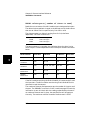
User’s Manual
3488 Mode Supplement
This manual describes the Agilent 3499A/B/C Switch/Control System
when used in the 3488 mode of operation. This manual is a supplement
to the Agilent 3499A/B/C Switch/Control System User’s Manual (shipped
with the instrument). Adobe Acrobat (PDF) versions of the user’s manual
are available at www.agilent.com.
© Copyright Agilent Technologies, Inc. 1999-2002
Agilent 3499A/B/C
Switch/Control System
Agilent 3499A/B/C at a Glance
The Agilent Technologies 3499A/B/C Switch/Control System provides a
convenient mechanical and programming environment for a variety of
plug-in modules. With appropriate plug-in modules, the Switch/Control
System provides high density/high speed switching and digital I/O
capability.
Switch/Control System Features
•
•
•
•
•
•
Intuitive and easy-to-use user interface
•
•
Relay cycle count information for preventive maintenance
GPIB (IEEE 488) or RS-232 interface control
External triggering capability
Built-in 4-bit digital I/O port
Store and recall up to 50 customized instrument setups
SCPI (Standard Commands for Programmable Instruments)
compatibility
Downloadable firmware upgrades
Agilent 3499A Features
•
•
Five plug-in slots
Full rack width
Agilent 3499B Features
•
•
Two plug-in slots
Half rack width
Agilent 3499C Features
•
•
Nine plug-in slots
Full rack width
Note: Unless otherwise indicated, this manual applies to all Serial Numbers.
2
Plug-in Modules at a Glance
The Agilent 3499A/B/C mainframes support a variety of plug-in modules
to make test system configuration easy.
Multiplexer Modules
N2260A 40-Channel MUX Module (armature relays)
N2266A 40-Channel MUX Module (reed relays)
N2270A 10-Channel High Voltage MUX Module
44470A 10-Channel MUX Module
44470D 20-Channel MUX Module
General Purpose Relay Modules
N2261A 40-Channel GP Relay Module
N2267A 8-Channel High Current GP Module
44471A 10-Channel GP Relay Module
44471D 20-Channel GP Relay Module
44477A 7-Channel Form-C Relay Module
Matrix Modules
N2262A 4 x 8 Matrix Module
44473A 4 x 4 Matrix Module
High Frequency Switching Modules
N2268A 50Ω 3.5GHz Dual 4-to-1 MUX Module
N2272A 1 GHz RF 1-to-9 MUX Module1
N2276A/B Dual 1-to-6 (4) Microwave MUX/Attenuator Module1
44472A Dual 4-Channel VHF Switch Module
44478A/B 50Ω/75Ω 1.3 GHz Multiplexer
44476A 3-Channel 18 GHz Switch Module
44476B 2-Channel Microwave Switch Module
Optical Switch Modules
N2280A Optical Switch Quad 1-to-2 MUX Module
N2281A Optical Switch Dual 1-to-4 MUX Module
N2282A Optical Switch 1-to-8 MUX Module1
Digital I/O Modules
N2263A 32-Bit Digital I/O Module
44474A 16-Bit Digital I/O Module
Multifunction/Special Purpose Modules
N2264A 12-Channel GP & 3-Channel High-current GP & 16-Bit Digital I/O
N2265A 4 x 4 Matrix & 16-Bit Digital I/O Module
44475A Breadboard Module
1
These modules are NOT supported in the 3488 Mode of operation.
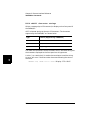
3
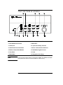
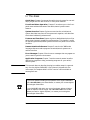
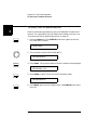
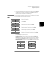
The Front Panel at a Glance
1. Power On/Standby
8. Scan Keys (see page 78)
2. Reset Module/Instrument
9. Main Menu
3. Shift/Local
10. Open/Close Relay Channels
4. Store/Recall Instrument State
11. Enter a Value/Confirm Selection
5. Monitor Channel/Port/Module
12. Read/Write Digital I/O Ports
6. View Menu
13. Knob
7. Mode Menu
14. Navigation Arrow Keys
Note
The front panel shown above is the Agilent 3499B. The 3499A and 3499C
front panels are similar and have identical functionality.
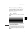
4
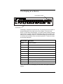
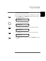
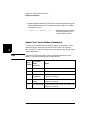
The Display at a Glance
Channel/Slot Number
Annunciators
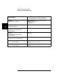
The display is divided into several areas. The channel and slot number is
always displayed on the right corner of the display. The main area,
which is in the center of the display, is primarily used to display channel
status (open or closed), information messages, menu items, prompt information, error messages, and so on. Around the display are annunciators
to indicate various states of the instrument operation. The annunciators
are summarized below.
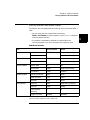
Annunciator
Indication
SCAN
Scan is initiated.
MON
Instrument is in monitor mode.
VIEW
Scan list, errors or relay cycle counts are being viewed.
CONFIG
Any configuration key has been pressed.
*
Instrument is advancing a scan step.
ADRS
Instrument is active on the remote interface.
RMT
Instrument is in remote mode.
ERROR
Error queue is not empty.
EXT
Scan is waiting for external trigger source.
SHIFT
Shift key has been pressed.
Other annunciators in the display are not used in the Agilent 3499A/B/C
system.
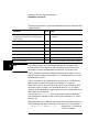
5
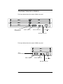
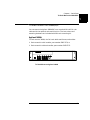
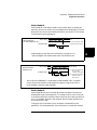
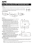
The Rear Panel at a Glance
The figure below shows the Agilent 3499A rear panel.
Slot 1
Slot 4
Slot 2
Slot 5
Slot 3
Slot 0
Control Module
GPIB Connector
RS-232 Connector
Power Input
Mini DIN Connector
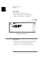
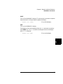
The figure below shows the Agilent 3499B rear panel.
Slot 1
Slot 2
Slot 0
Control Module
GPIB Connector
RS-232 Connector
Power Input
Mini DIN Connector
6
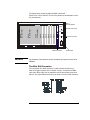
The figure below shows the Agilent 3499C rear panel.
Option FP1 (1-slot) and FP2 (2-slot) filler panels can be ordered to cover
any unused slots.
Slot 1
Slot 2
Slot 3
Slot 4
Slot 5
Mini DIN Connector
Slot 6
Slot 7
(2 slot width)
Slot 8
(3 slot width)
Slot 9
(3 slot width)
Slot 0
Control Module
GPIB Connector
WARNING
RS-232 Connector
Power Input
For protection from electrical shock, the power cord ground must not be
defeated.
The Mini DIN Connector
The rear panel mini DIN connector is used to make connections to
external triggers and the built-in digital I/O port. An Agilent N2289A
cable (mini DIN to D9) can be ordered to assist connections to external
devices. The figure below shows the pins used in the mini DIN connector.
7
In This Book
Quick Start Chapter 1 prepares the switch/control system for use and
helps you get familiar with a few of its front-panel features.
Front-Panel Menu Operation Chapter 2 introduces you to the frontpanel menu and describes some of the switch/control system’s menu
features.
System Overview Chapter 3 gives an overview of a switch/control
system, describes how parts of the system work together, and describes
the channel addressing scheme used.
Features and Functions Chapter 4 gives a detailed description of the
switch/control system’s capabilities and operation. This chapter is useful
for operating the switch/control system from the front panel or the remote
interface.
Remote Interface Reference Chapter 5 contains the 3488 mode
language reference used to program the switch/control system over a
remote interface.
Error Messages Chapter 6 lists the error messages that may appear as
you are working with the instrument.
Application Programs Chapter 7 contains several remote interface
application programs to help you develop programs for your switch/
control system.
Note
This manual does not describe the plug-in modules except in a general
way. Use the Agilent 3499A/B/C User’s Manual (shipped with the
instrument) for complete details. A PDF version is also available at
www.agilent.com.
If you have questions relating to the operation of the Agilent 3499A/B/C,
call 1-800-452-4844 in the United States, or contact your nearest Agilent
Technologies Sales Office.
If your 3499A/B/C fails within one year of purchase, Agilent will either
repair or replace it free of charge. Call 1-877-447-7278 in the United
States (and ask for “Agilent Express”) or contact your local Agilent
Technologies Sales Office.
8
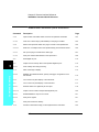
Contents
Chapter 1 Quick Start 11
To Prepare the Instrument for Use 13
To Install a Module in the 3499A/B/C 15
Basic Operation 17
To Rack Mount the 3499A/B/C 21
Filler Panels 24
Chapter 2 Front-Panel Operation 25
Contents
To Power On the Instrument 27
To Select the System Mode 27
To Monitor a Channel or a Slot 28
To Use a Digital I/O Port 30
To View Instrument Errors 35
Scanning Operation 37
To Pair Two Modules Together 40
To Configure for External Trigger 41
To Configure the Power-on State 43
To Configure the Remote Interface 45
To Perform a Self-test 47
To Query the Firmware Revision 48
To Query the Serial Number 49
Local/Remote Control 50
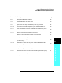
Chapter 3 System Overview 51
Agilent 3499A/B/C Switch/Control System 53
Mainframes Overview 54
Firmware and Control Module Description 55
3488 Mode Differences 57
Plug-in Modules Overview 58
Channel and Slot Addressing 67
Factory Default and Reset States 71
9
Contents
Chapter 4 Features and Functions 73
Monitoring a Channel or a Slot 75
Switching a Relay Channel 77
Scanning 78
Digital I/O Operation 84
State Storage 94
Error Conditions 96
Self-Test 96
Display Control 97
Relay Cycle Counts 98
Contents
Chapter 5 Remote Interface Reference 99
Command Syntax 101
3488 Mode Command Quick Reference 102
3488 Mode Commands 104
Chapter 6 Error Messages 135
Error Messages 136
Self Test Errors 136
Chapter 7 Application Programs 137
Visual C++ Example Program 139
Visual BASIC Example Program 141
BASIC Example Program 143
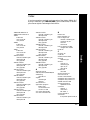
Index 145
10
1
1
Quick Start
Quick Start
1
This chapter describes the procedure to install the plug-in modules into
an Agilent 3499A/B/C mainframe and mount the mainframe onto a
system rack. The basic operations of the Agilent 3499A/B/C Switch/
Control System is also described. The chapter contents include:
•
•
•
•
12
To Prepare the Instrument for Use, on page 13
To Install a Module in the 3499A/B/C, on page 15
Basic Operation, on page 17
To Rack Mount the 3499A/B/C, on page 21
Chapter 1 Quick Start
To Prepare the Instrument for Use
1
To Prepare the Instrument for Use
1 Check the list of supplied items
Verify that you have received the following items with your
Agilent 3499A/B/C mainframe:
❏ One power cord;
4
❏ This User’s Manual;
❏ One Quick Reference Guide;
❏ One Tie Down Clip 03499-21002 (for Agilent 3499B only);
❏ Any plug-in modules that you ordered are delivered in separate
shipping containers.
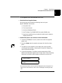
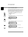
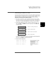
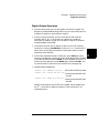
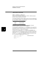
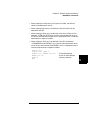
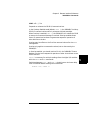
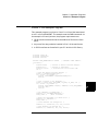
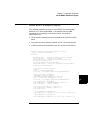
2 Connect the power cord and turn on the instrument
1. Connect the 3499A/B/C to an AC power source with the supplied
power cord.
2. Push the Power switch located on the lower left side of the front
panel.
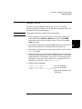
3. On power-up, every segment in the display will light up briefly,
including all annunciators. Following this “starburst” display, the
internal self-test will begin.
4. If the self-test passes 1, the default system mode and the GPIB
address are displayed, together with a “beep” sound. Then the display
shows the instrument model number and the active slot (slot 0).
SCPI GPIB 9
3499
1
0
If the self-test failed, the failure will be displayed on the front panel. For
details of all self-test errors, refer to “Error Messages” starting on page
135.
13
Chapter 1 Quick Start
To Prepare the Instrument for Use
1
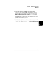
When shipped from the factory, the SCPI mode and the GPIB interface
address of “9” are used. Slot 0 refers to the built-in controller board of the
switch/control system.
If the Instrument Does Not Turn On
1. Verify that the power cord is firmly plugged into the power receptacle
on the rear panel of the 3499A/B/C.
2. Make sure that the power source the 3499A/B/C is plugged into is
energized.
3. Verify that the 3499A/B/C is turned on.
Note
If the 3499A/B/C DOES NOT turn on after you perform the above
procedure, contact your nearest Agilent Service Center (see page 8).
14
Chapter 1 Quick Start
To Install a Module in the 3499A/B/C
1
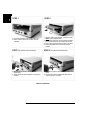
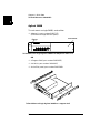
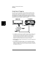
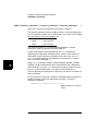
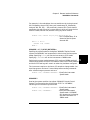
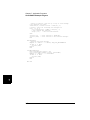
To Install a Module in the 3499A/B/C
The plug-in modules you ordered were not installed in the mainframe.
The figure on page 16 shows how to install a plug-in module into the
3499B mainframe. Other mainframes use similar procedures.
WARNING
Disconnect the power cord from the rear panel of the mainframe prior to
4
installing or removing any modules.
Caution
Use anti-static procedures when configuring, installing or removing any
plug-in modules. To prevent contamination to the modules that could
degrade performance, handle the modules by the side edges or shields
only. Do not touch the board surfaces or components.
Each plug-in module may have terminal block(s) and/or the cables for
wiring to external circuits. These terminations are also shipped
separately.
For more details about terminal blocks, cables, and connections, see the
Agilent 3499A/B/C User’s Manual (shipped with the instrument) or visit
www.agilent.com.
Module Removal
To remove a plug-in module from the Agilent 3499A/B/C mainframe,
reverse the procedures shown on page 16.
15
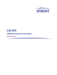
1
STEP 2
STEP 1
1. Face the mainframe rear panel toward you.
2. Select a slot in which the module is to be
installed.
1. Hold the sides of the module, component side
down, by the metal shields.
2. Insert the module into the slot guides and slide
the module toward the front of the instrument.
3. Push firmly until the module “snaps” into place.
4. Push both plastic levers inward to lock the
module.
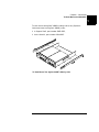
STEP 3 (for modules with terminal blocks)
STEP 4 (for modules with terminal blocks)
1. Wire the screw terminal block (module
dependent).
2. Attach the screw terminal block to the plug-in
module.
1. Push firmly until the terminal block “snaps” into
place.
2. Secure the screw terminal block with the two
screws (Torque < 8 in-lbs).
Module installation
16
Chapter 1 Quick Start
Basic Operation
1
Basic Operation
An Agilent 3499A/B/C Switch/Control System can be easily operated
from the front-panel, or programmed with SCPI commands over the
remote interface.
The following sections are only intended to show the basic front-panel
operation. For detailed front-panel operation, refer to the “Front-Panel4
Operation” chapter on page 25. For more information about
programming the instrument, refer to the “Remote Interface Reference”
chapter on page 99.
Channel Addressing
A channel refers to an individual relay on a switching module, or an
individual bit/port on a digital I/O module. The channel address is in the
form of snn, where s represents slot number and nn represents a channel
number.
For all mainframes, slot 0 refers to the 3499 controller board. Valid slot
numbers are:
3499A slots 0 through 5
3499B slots 0 through 2
3499C slots 0 through 9
The channel number, nn, is plug-in module dependent. For additional
information about channel numbers of individual plug-in modules, refer
to the table beginning on page 67.
17
Chapter 1 Quick Start
Basic Operation
1
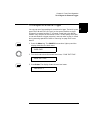
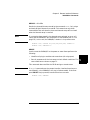
To Select a Slot and Channel
When the instrument is first turned on, the display shows the model
number and the slot number of the controller board.
3499
0
Use the knob to select a channel on the active slot. For example, with the
display shown above, turning the knob to the right will select the first of
the individual built-in digital I/O ports.
DIN
090
The “DIN” indicates the port is set for a digital input operation. As the
knob is turned, the additional ports are displayed followed by any
installed plug-in modules.
If you have installed one or more plug-in modules, you can select the
module by pressing the right arrow key. For example, if an N2260A (40channel MUX module) is installed in slot 1, pressing the right arrow key
will show the module name and slot number.
N2260A
1
Turning the knob will then step through the individual channels on that
module.
MUX
18
OPEN
100
Chapter 1 Quick Start
Basic Operation
1
To Open or Close a Channel
When a channel is selected, you can open or close the channel using the
front panel keys. For example, with an N2260A 40-channel MUX
installed in slot 1, select channel 00 as described on the previous page.
MUX
OPEN
100
4
Press the CLOSE key to close the channel.
MUX
CLOSED 100
Press the OPEN key to open the channel
MUX
OPEN
100
In this manner, you can select and control as many channels as you need.
The N2260A has 40 channels numbered 0 through 39 (in slot 1, 100
through 139). You may also select additional plug-in modules and
channels by turning the knob.
19
Chapter 1 Quick Start
Basic Operation
1
To Open All Channels on a Module
You can open individual channels on a module one at a time as described
above. There are times, however, when it would be more expedient to
open all channels on a module at once.
Use the arrow keys to select the module to work with. You cannot have
an individual channel selected for this operation. For example, select the
module in slot 1 (using the N2260A as an example) to show a display
similar to this:
N2260A
1
Press and hold the card reset key. When you first press the key, the
display shows:
HOLD TO RESET
When the card has been reset, the display briefly shows:
RESET CARD
and then returns to:
N2260A
1
To Reset All Modules
You can reset all channels on all modules in the mainframe at once.
Press the shift key and then press and hold the reset key. The display
shows:
HOLD TO RESET
When the mainframe has been reset, the display will briefly show the
reset and then return to the slot or channel display.
RESET . . .
20
Chapter 1 Quick Start
To Rack Mount the 3499A/B/C
1
To Rack Mount the 3499A/B/C
You can mount the Agilent 3499A/B/C on a standard 19-inch EIA rack
cabinet with the optional rack-mounting kits. The instructions and
mounting hardware are included with each rack-mounting kit.
Agilent 3499A
4
To rack mount a 3499A, the full-rack-width mainframe, order either:
•
•
Rack-mount kit with handles, part number 5183-7170, or
Rack-mount kit without handles, part number 5183-7171.
3499A
SWITCH/CONTROL SYSTEM
To Rack Mount an Agilent 3499A
21
Chapter 1 Quick Start
To Rack Mount the 3499A/B/C
1
Agilent 3499B
To rack mount a single 3499B, order either:
•
Adapter kit, part number 5183-7172
(includes the flange and filler panel).
Flange
Filler Panel
3499B
SWITCH/CONTROL SYSTEM
To Rack Mount a Single Agilent 3499B with Adapter kit 5183-7172
OR
•
•
•
A Support Shelf, part number 5063-9255,
A slide kit, part number 1494-0015,
And a filler panel, part number 5002-3999.
To Rack Mount a Single Agilent 3499B on a support shelf
22
Chapter 1 Quick Start
To Rack Mount the 3499A/B/C
1
To rack mount two Agilent 3499B’s side-by-side (or any System II
instrument next to an Agilent 3499B), order:
•
•
A Support Shelf, part number 5063-9255,
And a slide kit, part number 1494-0015.
4
To Rack Mount Two Agilent 3499B’s Side-by-side
23
Chapter 1 Quick Start
Filler Panels
1
Agilent 3499C
To rack mount an Agilent 3499C, order either:
•
•
Adapter kit without handles, part number 5063-9216, or
Adapter kit with handles, part number 5063-9223.
Adapter kit
To Rack Mount an Agilent 3499C
Filler Panels
Order filler panels to cover any unused slots in an Agilent 3499A/B/C.
•
•
24
1-slot filler panel, part number 03499-00023 (option FP1)
2-slot filler panel, part number 03499-00024 (option FP2)
2
2
Front-Panel Operation
Front-Panel Operation
2
The Agilent 3499A/B/C mainframes all operate the same from the frontpanel. This chapter does not give a detailed description of every possible
front-panel operation. It does, however, give you a good overview of the
front-panel menus and front-panel keys. See the “Features and
Functions” chapter on page 73 for additional discussions of the
instrument’s capabilities and operation. This chapter contents include:
•
•
•
•
•
•
•
•
•
•
•
•
•
•
To Power On the Instrument, on page 27
To Select the System Mode, on page 27
To Monitor a Channel or a Slot, on page 28
To Use a Digital I/O Port, on page 30
To View Instrument Errors , on page 35
Scanning Operation, on page 37
To Pair Two Modules Together, on page 40
To Configure for External Trigger, on page 41
To Configure the Power-on State, on page 43
To Configure the Remote Interface, on page 45
To Perform a Self-test, on page 47
To Query the Firmware Revision, on page 48
To Query the Serial Number, on page 49
Local/Remote Control, on page 50
The following conventions are used for the front-panel operation.
•
All keys on the front-panel keyboard are expressed in bold font and
normally associated with a “press”. For example, press Mon.
•
All the front panel display annunciators are expressed in bold font
followed by an “annunciator”. For example, MON annunciator.
•
The information shown on the front panel display is enclosed within a
pair of quotation marks.
26
Chapter 2 Front-Panel Operation
To Power On the Instrument
To Power On the Instrument
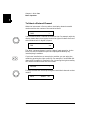
To power on the instrument, press the power switch on the front panel.
If the instrument is powered up for the first time, the instrument will
use the factory default settings as shown on page 71. Otherwise, the
instrument will power on to the state specified. Refer to "To Configure
the Power-on State", on page 43 for more details.
4
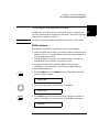
To Select the System Mode
The instrument can be operated in either SCPI mode or 3488A mode
(except Firmware REV 3.0, see page page 55 for more details). When
shipped from the factory, the instrument is set to the SCPI mode.
Perform the following procedure to select the desired system mode for
the instrument before any operation.
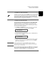
1. Press Menu, the CONFIG annunciator lights up. Turn the knob
until “SYSTEM MODE” is displayed, then press Enter.
SYSTEM MODE
2. Turn the knob until the desired system mode (i.e. 3488A MODE) is
displayed, then press Enter.
HP 3488A MODE
3. The instrument will be reset if the system mode has been changed.
Otherwise, it retains the current mode and you can press Menu
again to exit this operation.
Note
Switching between SCPI mode and 3488A mode will reset the
instrument to the factory default settings, except the GPIB address
which will retain its last setting.
This manual describes programming in the 3488 mode. For information
about the SCPI programming mode please refer to the User’s Manual
shipped with the Agilent 3499A/B/C, or visit www.agilent.com.
27
2
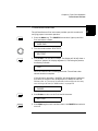
Chapter 2 Front-Panel Operation
To Monitor a Channel or a Slot
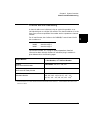
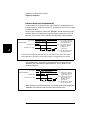
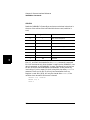
To Monitor a Channel or a Slot
2
You can continuously monitor the current status of a particular
switching channel, a digital I/O port, or an entire plug-in module.
Monitoring from the front panel is especially useful when developing and
debugging remote interface commands.
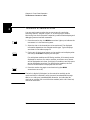
1. Press the monitor key, the MON annunciator lights up to indicate the
instrument is in the monitoring state.
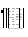
2. Select the slot or the channel/port to be monitored. The displayed
information depends on the selected module type. Typical displays
are shown in the table on page 76.
3. If only part of the channel status on the module can be displayed at
one time, press Enter to display the next part.
For multiplexer modules and GP Relay modules, 10 channels can be
displayed at one time; for matrix modules, one Row or one Column
can be displayed at one time; for digital I/O modules, two 8-bit ports
can be displayed at one time. For multifunction modules, the first
function on the module is displayed, then the next.
4. Press the monitor key again to end monitoring (the MON
annunciator turns off).
Note
The built-in digital I/O bits/port (on the controller module) can be
monitored either individually as bit channels (numbered 091 through
094) or as a 4-bit port (numbered 090). However, the individual bit
channels on a digital I/O or multifunction module (with a DIO function)
cannot be monitored.
28
Chapter 2 Front-Panel Operation
To Monitor a Channel or a Slot
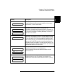
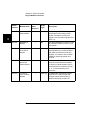
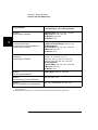
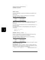
.
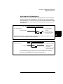
Display
Description
1:0,,,,,,6,,,9,
2
2
The display for a multiplexer or a GP relay module. This
display indicates that the monitored module is in Slot 2 and
channels 10, 16, and 19 are closed.
4
ROW 3:,1,,3,,,6,7
3
0;,,3,COL 3,
3
00:H255
DIO
DOUT
L254.
4
12
090
0
091
ROW 0:,1,,3,
5
00:H255
5
L254.
The display for a matrix module. The top is the row
information, indicating that the relays on Row 3, Columns 1, 3,
6 and 7 of the module (in Slot 3) are closed. The lower display
is the column information, indicating that relays on column 3,
row 0 and 3 are closed.
The display for a digital I/O module. The first 2 digits on the left
(“00” in this case) represents the “L” 8-bit port address. Adding
one to this value, the “H” 8-bit port address is obtained. Data
with a trailing decimal point indicates that the last operation on
that port was a WRITE, data without a trailing decimal point
indicates that the last operation on that port was a READ. This
display shows that the data last read from Port 401 is 255 and
the data last written to Port 400 is 254.
The top display is for the built-in digital I/O Port 090 (control
module) and the data from the last operation.
The lower display indicates that data last written to the bit
channel 091 is 0.
For a multifunction module, the first function on the module is
displayed, then the next. This display is an example of a
multifunction module with matrix and DIO functions (in slot 5).
29
Chapter 2 Front-Panel Operation
To Use a Digital I/O Port
To Use a Digital I/O Port
2
You can work with a digital I/O module as a port (all eight bits) or as
individual bits.
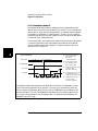
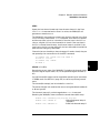
Reading a Digital I/O Port
You can read data from the built-in 4-bit digital I/O port, or any one of
the 8-bit ports on a digital I/O or multifunction module (with a DIO
function). You can read the entire port (all bits) when you select the slot
(for example, the built-in port is channel 090). Alternately, you can read
an individual bit by selecting the channel (for example the first bit in the
built-in port is channel 091).
Perform the following procedure to read from a port:
1. Select a digital I/O port. Use the knob to select the slot and channel
number. The channel number is in the form of snn, where s is the slot
number and nn is the channel number.
2. Read the data read from the selected port. For example, the display
below shows the data read from port 401.
DIN
255 401
DIN
11111111 401
Decimal format
(default)
Binary format
The data display format of individual 8-bit ports can be specified
either in binary or decimal formats (as described on page 33). Once
specified, the format applies to all input and output operations on the
same port.
30
Chapter 2 Front-Panel Operation
To Use a Digital I/O Port
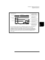
Writing to a Digital I/O Port
You can write data to the built-in digital I/O port (numbered 090) or to
one of the built-in digital I/O port bits (numbered 091 through 094), or
any one of the 8-bit ports on a digital I/O or multifunction module (with a
DIO function). To write to a port:
1. Select a digital I/O port. Use the knob to select the slot and channel
number. The channel number is in the form of snn, where s is the slot
4
number and nn is the channel number. In the display, “DIN”
indicates that the last operation on the port was a READ, and
“DOUT”, a WRITE.
DIN
401
2. Press the Write key. “DOUT” is displayed to indicate the port is now
an output port. The current port value is displayed.
DOUT
255 401
3. Edit the value. Use the arrow keys to select the to-be-edited bit (the
digit to be edited is set to half bright in the display).
Turn the knob to modify the value. Use the arrow keys to select the
next digit and the knob to modify its value.
DOUT
254 401
4. When the value is the one desired, press Enter to output the data to
the selected port.
5. Press Write again to cancel the current write operation.
Note
Data display format of individual 8-bit ports can be specified either in
binary or decimal values (refer to the procedure on page 33). Once
specified, the format applies to all input and output operations on the
same port.
31
2
Chapter 2 Front-Panel Operation
To Use a Digital I/O Port
To Configure a Digital I/O Module
2
Digital I/O modules can be configured for handshake modes and control
line, flag line, and I/O line polarity. Use the Mode menu to configure
digital I/O parameters. See “Digital I/O Operation” on page 84 for
detailed descriptions of the operating modes. Only plug-in modules can
be configured this way, the built-in digital I/O port (control module) can
only be configured at the port level (see page 33).
The following procedure configures a plug-in digital I/O module to use a
two line digital handshake mode (mode 5) for data transfers.
1. Select the slot in which a digital I/O or multifunction module is
installed. The channel number is in the form of snn, where s is the
slot number and nn is the channel number.
N2263A
4
2. Press the Mode key. The CONFIG annunciator lights up in the
display and the first-level menu is shown.
CONFIG DIO
4
3. Press Enter to begin the configuration. The display shows the
second-level menu choice.
MODE 1
4
4. Turn the knob until the desired flow control mode (i.e., MODE 5) is
displayed. The displayed mode is half-bright.
MODE 5
32
4
Chapter 2 Front-Panel Operation
To Use a Digital I/O Port
5. Press Enter to select the new mode. The display changes to show the
next menu level.
CONT POL POS
2
4
6. You may change other configuration parameters as desired using the
same procedure. When all desired configurations have been made,
4
press the Mode key to exit the configuration menu. The CONFIG
annunciator turns off.
To Configure a DIO Port
You can configure an individual digital I/O port to change the data
polarity and the display format. The following procedure changes the
built-in digital I/O port to display in binary number format.
1. Select a digital I/O port (i.e., port 090). The channel number is in the
form of snn, where s is the slot number and nn is the channel number.
DIN
090
2. Press the Mode key. The CONFIG annunciator lights up in the
display. The first level menu is shown:
DATA POLARITY
090
3. Turn the knob to select the second menu level
DISP FORMAT
090
4. Press Enter to select the format parameter.
DECIMAL
090
33
Chapter 2 Front-Panel Operation
To Use a Digital I/O Port
5. Turn the knob until the desired data display format (i.e., BINARY) is
displayed.
2
BINARY
090
6. Press Enter to make the change and return to the first level of the
Mode menu.
DISP FORMAT
401
7. Press Mode again to exit the current configuration, the CONFIG
annunciator turns off.
Note
Once you have selected the data display format for a port, it applies to
both input and output operations on that port.
34
Chapter 2 Front-Panel Operation
To View Instrument Errors
To View Instrument Errors
You can view errors from the front panel. This feature is especially
useful when developing remote instrument control. If an error occurs,
the ERROR annunciator in the display will light. Errors are stored in
the error queue in the order they occur. You read the errors in the same
order. After all errors have been read, the queue is empty and the
4
ERROR annunciator turns off. To view instrument errors:
1. Press the View key. The VIEW annunciator lights up and the display
shows the first menu level.
ERROR
0
2. Press Enter to view the first error.
a. If no error is in the error queue (the ERROR annunciator is off),
the display shows “NO ERROR” and then automatically returns to
the first level of the View menu.
NO ERROR
0
ERROR
0
b. If there are errors (the ERROR annunciator is on), the first error
in the error queue is displayed.
01:ERR -109
Press the right arrow key to scroll the display to show the entire
error message.
MISSING PARAMETER
35
2
Chapter 2 Front-Panel Operation
To View Instrument Errors
3. Turn the knob to view other errors in the error queue (if any).
2
4. Press Enter to return to the first level of the View menu, the
ERROR annunciator turns off.
5. Press View again to exit the View menu operation, the VIEW
annunciator turns off.
Note
All errors are cleared, and the ERROR annunciator turns off, once the
error queue is viewed. See the “Error Messages” chapter on page 135 for
a complete list of error messages.
36
Chapter 2 Front-Panel Operation
Scanning Operation
Scanning Operation
The instrument allows you to combine an external measurement device
such as a Digital Multimeter (DMM) with multiplexer channels to create
a scan. During a scan, the instrument closes the configured multiplexer
channels one at a time to allow a measurement to be made on that
channel.
4
Before initiating a scan, a scan list must be set up. You can also specify
an arm source, a trigger source, and the number of sweeps (a sweep is
one pass through the scan list) to control the scan process. All these can
be done from the S.List menu. The procedure in this chapter describes a
simple scan from the front panel. For more information about scanning
and using the parameters to control a scan, see page 78.
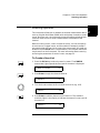
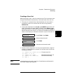
To Create a Scan List
1. Press the S.List key to enter the scan list menu. The CONFIG
annunciator lights up and the first level of the menu is displayed.
ADD TO SCAN
101
2. Press Enter to begin the channel selection.
SELECT
101
3. Turn the knob to select the first channel for the list (e.g., 103).
SELECT
103
4. Press Enter to add the channel into the scan list. The starburst
character lights in the display to indicate the channel is now a part of
the scan list.
SELECT
*
103
37
2
Chapter 2 Front-Panel Operation
Scanning Operation
5. Repeat step 3 and 4 to add additional channels to the list.
2
6. When the desired channels have been added, press the S.List key
again to return to the first level of the menu.
ADD TO SCAN
107
7. Press S.List again to exit the menu. The CONFIG annunciator turns
off.
To Perform Scanning
After the scan configuration is complete, the actual scan can be
performed.
1. Press the Step key to close the first channel in the scan list.
2. Press the Step key again to open the first channel and close the next
channel in the list.
This procedure shows a simple way to scan, one channel at a time for
each press of a front panel key. You can also press the Scan key to scan
all channels in the list according to the various scan parameters set. In
the default parameter state, pressing the Scan key will cause all the
channels in the list to cycle through at the maximum possible speed.
While this occurs, the SCAN annunciator is lighted. For details about
the scan parameters, see page 78.
To Clear a Scan List
You can clear a scan list once it has been configured.
1. Press the Shift key and then the S.List key. The display will briefly
show:
CLR SCAN LIST
101
and then return to normal operation.
38
Chapter 2 Front-Panel Operation
Scanning Operation
To View a Scan List
You can view which channels are included in a scan list. This example
assumes that channels 103 through 107 are included in the scan list.
2
1. Press the View key. The VIEW annunciator lights up and the display
shows the first level menu.
ERROR
101
4
2. Turn the knob until “SCAN LIST” is displayed.
SCAN LIST
101
3. Press Enter. The first channel in the scan list is displayed on the
channel area.
001 OF 005
103
Turn the knob to view other channels in the scan list.
002 OF 005
104
4. Press Enter to return to the first level of the View menu.
SCAN LIST
107
5. Press View again to exit the View menu. The VIEW annunciator
turns off.
39
Chapter 2 Front-Panel Operation
To Pair Two Modules Together
To Pair Two Modules Together
2
You can pair two modules together so that they operate as a single unit.
The two modules to be paired must be identical (that is, they must have
the same model number) and be installed in the same mainframe. When
two modules are paired together, any operation on a channel of one
module will be duplicated on the corresponding channel of the other
module. The example below pairs modules installed in slots 2 and 5.
1. Press the Menu key. The CONFIG annunciator lights up and
“CARD PAIR” is displayed.
2. Press Enter.
When “FIRST SLOT x” is displayed, turn the knob to select the first
slot to be paired (i.e., Slot 2).
FIRST SLOT 2
3. Press Enter.
When “SECOND SLOT x” is displayed, turn the knob to select the
second slot to be paired (i.e., Slot 5) .
SECOND SLOT 5
4. Press Enter to return to the first level of the Menu menu.
CARD PAIR
5. Press Menu again to exit the Menu menu. The CONFIG annunciator
turns off.
40
Chapter 2 Front-Panel Operation
To Configure for External Trigger
To Configure for External Trigger
You can use one of two modules for an external trigger. The built-in rear
panel TRIG IN and TRIG OUT pair (on the control module) or the EI
(External Increment) and the CC (Channel Closed) pair on a 44474A
module. Only one pair can be used at a time. You can specify which pair
to use and whether a trigger out pulse is sent out when a relay is closed
during scanning operations. Refer to “Scanning” on page 78 for more 4
details.
1. Press the Menu key. The CONFIG annunciator lights up and the
display shows the first level menu.
CARD PAIR
2. Turn the knob to show the second menu item, “CONF EXT TRIG”.
CONF EXT TRIG
3. Press Enter. The display shows the next level menu.
TRIG SLOT 0
41
2
Chapter 2 Front-Panel Operation
To Configure for External Trigger
2
4. Turn the knob to select the slot for the external trigger. Slot 0 (control
module) is the built-in external trigger (available at the rear panel
mini DIN connector, see page 7). If a 44474A is not installed, only slot
0 will be shown. Press Enter. The display shows the current setting
for the external trigger.
DISABLE
5. Turn the knob to show the alternate choice.
ENABLE
6. Press Enter to accept the choice and return to the first level menu.
CONF EXT TRIG
7. Press the Menu key to exit the menu. The CONFIG annunciator
turns off.
42
Chapter 2 Front-Panel Operation
To Configure the Power-on State
To Configure the Power-on State
2
Firmware Rev 4.0 ONLY. To read your firmware version, see the
procedure on page 48. For more information about firmware revisions,
see “Firmware and Control Module Description” on page 55.
An instrument with Firmware REV 4.0 or later can be set to power on to
the reset state (see “Factory Default and Reset States” on page 71) or to4
a
state previously stored in a specified memory location. The instrument
will return to the specified state the next time it is turned on.
1. Press the Menu key. The CONFIG annunciator lights up and the
display shows the first menu level.
CARD PAIR
2. Turn the knob until “POWER ON SET” is displayed.
POWER ON SET
3. Press Enter to show the second level menu.
PWR ON RESET
4. To set the instrument power-on to the reset state, press Enter. The
instrument will return to the first level menu.
Alternately, to set the instrument power-on to a stored state: Turn
the knob until “USER SET UP” is displayed.
USER SET UP
5. Press Enter to select the stored state to use.
POWER ON 05
43
Chapter 2 Front-Panel Operation
To Configure the Power-on State
6. Turn the knob to select the desired memory location (i.e., 08).
POWER ON 08
2
7. Press Enter to accept the stored state and return to the first level
menu. More information about storing states is given on page 94 of
this manual.
POWER ON SET
8. Press the Menu key again to exit the Menu menu. The CONFIG
annunciator turns off.
Note
If the instrument is set to power on to a previously stored setup that is
no longer valid, it will automatically power on to the reset state and
“RECALL FAILED” will be displayed.
44
Chapter 2 Front-Panel Operation
To Configure the Remote Interface
To Configure the Remote Interface
In 3488 mode, the instrument can communicate with a computer over
the GPIB interface. When shipped from the factory, the GPIB interface is
selected and its address is set to “9”.
Note
The RS-232 interface can be configured and used only in SCPI mode.
4
GPIB Interface
Each device on the GPIB interface must have a unique address.
•
When shipped from the factory, the GPIB interface is selected and its
address is set to “9”. The GPIB address of the instrument can be set to
any value between 0 and 30.
•
The GPIB address is stored in non-volatile memory, and does not
change when the instrument is turned off or reset.
•
Switching between SCPI mode and 3488A mode causes the
3499A/B/C to select the GPIB interface and its address setting.
To set the GPIB interface:
1. Press the Menu key. The CONFIG annunciator lights up and the
first level menu is shown.
CARD PAIR
2. Turn the knob to select “INTERFACE” in the menu.
INTERFACE
3. Press Enter to show the second level menu The active interface is
shown. If necessary, turn the knob until “GPIB/488” is displayed.
GPIB/488
45
2
Chapter 2 Front-Panel Operation
To Configure the Remote Interface
4. Press Enter to select the interface and show the first parameter.
ADDRESS 09
2
5. Turn the knob to set GPIB address (i.e., 07). Valid addresses range
from 00 to 30.
ADDRESS 07
6. Press Enter to show the second parameter.
SRQ ON
7. Press Enter to enable the instrument to assert the SRQ line when
powered up. If the computer is so configured, this can be used to
interrupt the system computer.
To disable this feature, turn the knob to select “SRQ OFF” and press
Enter. The instrument returns to the first level of the menu.
8. Press Menu again to exit the menu.The CONFIG annunciator turns
off.
46
Chapter 2 Front-Panel Operation
To Perform a Self-test
To Perform a Self-test
2
The self-test feature of the instrument provides you with a method of
verifying proper instrument operation.
1. Press the Menu key. The CONFIG annunciator lights up and the
first level menu is shown.
4
CARD PAIR
2. Turn the knob to select “SELFTEST”.
SELFTEST
3. Press Enter. The self test will begin. The display will briefly show a
“starburst” pattern (all display segments lit). Following the pattern,
the display indicates:
TEST. . .
while the internal tests are being performed. The self-test takes
several seconds to complete.
If the self-test is successful, “PASSED” will be displayed. Otherwise,
the reason of the failure will be displayed. For details on self-test
failures, refer to “Th e errors listed below in dicate failu res tha t m a y
occu r during a self-test (in 3488A m ode).” on page 1 36.
PASSED
4. Press Enter to return to the first level of the menu.
SELFTEST
5. Press Menu again to exit the Menu menu, the CONFIG annunciator
turns off.
47
Chapter 2 Front-Panel Operation
To Query the Firmware Revision
To Query the Firmware Revision
2
Perform the following procedure to query the 3499A/B/C firmware and
revision. For a description of the firmware and hardware revisions, see
“Firmware and Control Module Description” on page 55.
1. Press the Menu key. The CONFIG annunciator lights up and the
first level menu is shown.
CARD PAIR
2. Turn the knob to select “REVISION INFO”.
REVISION INFO
3. Press Enter. The system firmware revision number will be displayed.
REVISION 4.0 2.0
4. Press Enter to return to the first level of the Menu menu.
REVISION INFO
5. Press Menu again to exit the Menu menu, the CONFIG annunciator
turns off.
48
Chapter 2 Front-Panel Operation
To Query the Serial Number
To Query the Serial Number
Perform the following procedure to query the 3499A/B/C serial number.
1. Press the Menu key. The CONFIG annunciator lights up and the
first level menu is shown.
CARD PAIR
4
1. Turn the knob to select “SERIAL NO”.
SERIAL NO
2. Press Enter. The Agilent 3499A/B/C serial number is displayed.
MY12345678
3. Press Enter again to return to the first level of the Menu menu.
SERIAL NO
4. Press Menu again to exit the Menu menu, the CONFIG annunciator
turns off.
49
2
Chapter 2 Front-Panel Operation
Local/Remote Control
Local/Remote Control
2
The instrument operates in two data entry modes, local and remote. In
local mode, all keys on the front panel are fully functional. In remote
mode, some front panel keys are locked (exception are: Local, Mon,
View, Enter, the arrow keys, and the knob).
The instrument will enter the remote state upon receipt of any command
over the remote interface. The RMT annunciator lights.
You can regain control of the front panel keys when the instrument is in
remote by pressing the Shift (Local) key. The RMT annunciator turns
off and the instrument return to local mode.
Note
If the front panel keys are locked through either the SYSTem:RWLock
command on the RS-232 interface or a LOCAL LOCKOUT command on
the GPIB interface, the local key will not function. You can restore the
front panel operation by cycling power the instrument or by sending a
SYSTem:LOCal command on the RS-232 interface, or a LOCAL command
on the GPIB interface.
50
3
3
System Overview
System Overview
An Agilent 3499A/B/C Switch/Control System is composed of a
mainframe and a set of Plug-in modules. This chapter provides a typical
configuration of a test system using the 3499A/B/C for switching and
control, followed by a description of the three mainframes and all the
Plug-in modules. The following sections are included in this chapter:
3
•
•
•
•
•
•
•
52
Agilent 3499A/B/C Switch/Control System, on page 53
Mainframes Overview, on page 54
Firmware and Control Module Description, on page 55
3488 Mode Differences, on page 57
Plug-in Modules Overview, on page 58
Channel and Slot Addressing, on page 67
Factory Default and Reset States, on page 71
Chapter 3 System Overview
Agilent 3499A/B/C Switch/Control System
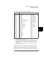
Agilent 3499A/B/C Switch/Control System
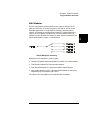
The Agilent 3499A/B/C Switch/Control System provides high density and
high speed switching for routing test signals to and from your DUTs
(devices under test) and test instruments such as external DMMs,
scopes, counters, power supplies, etc. Whether you are involved in a
large production test system or a small R&D bench top system, the
Agilent 3499A/B/C provides an ideal combination of price/performance 4
solution. With a wide variety of available plug-in modules, you can
configure your test system much more easily and flexibly. The figure
below shows the typical configuration of a test system.
DUT
Agilent 3499A/B/C
Plug-in
Modules
Source(s)
Instrument
Device(s)
Custom
Equipment
IEEE488.2 (GPIB)
A Typical Test System
53
3
Chapter 3 System Overview
Mainframes Overview
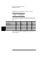
Mainframes Overview
Three mainframes are available:
3
1
Slots Available
Rack Width
3499A
5
full width
3499B
2
half width
3499C
91
full width
The 3499C is designed to accommodate multiple width plug-in modules and has 9 logical
slots but 14 mechanical slots. Slots 1 through 6 are 1-slot wide, slot 7 is 2-slots wide, and
slots 8 and 9 are each 3-slots wide. See the figure on page 7 for more information.
All mainframes can be either operated from the front-panel or
programed over a remote interface (GPIB or RS-232).
The mainframes can be operated in either of two system modes: SCPI
mode or 3488A mode. The SCPI mode allows the full realization of
performance potentials and advanced features, such as parallel
operation of multiple relays on multiple modules. The 3488A mode is
included for backward compatibility with the legacy Agilent 3488A
system. This manual documents the 3488 mode of operation.
For information about the SCPI programming mode please refer to the
User’s Manual shipped with your Agilent 3499A/B/C, or visit
www.agilent.com.
54
Chapter 3 System Overview
Firmware and Control Module Description
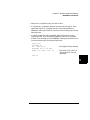
Firmware and Control Module Description
The Agilent 3499A/B/C and this manual support two versions of the
Agilent 3499A/B/C control module and four versions of firmware.
Firmware revisions and control module versions can be queried from the
front-panel. See page 48 for a procedure to read the revision from the
front-panel.
4
From the front-panel:
Control Module Revision Firmware Revision
Typical Display
1.0
1.0
REVISION 1.0
1.0
2.0
REVISION 2.0
1.0
3.0
REVISION 3.0
2.0
4.0
REV 4.0 2.0
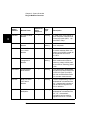
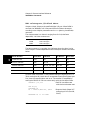
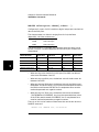
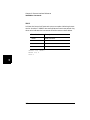
The table on the next page lists the differences between firmware and
control module revisions.
55
3
Chapter 3 System Overview
Firmware and Control Module Description
State
Storage
Plug-in module
Support
Programming
Modes
Firmware
Upgrade
Needed?
1.0
Stored setups
are cleared if
power is
cycled.
Must upgrade
hardware and
firmware.
Not Applicable
YES
2.0
1.0
Stored setups
are cleared if
power is
cycled.
Supports all
modules except:
N2272A
N2276A/B
N2282A
Firmware
Version 2.0
allows
programming in
both SCPI
Mode and
3488A Mode.
Upgrade to
Firmware
Revision 3.0
ONLY if using
N2272A,
N2276A/B, or
N2282A.
3.0
1.0
Stored setups
are cleared if
power is
cycled.
SCPI Mode
supports all
modules.
3488A Mode
supports all
modules except:
N2272A,
N2276A/B, or
N2282A.
Firmware
Version 3.0
limits
programming to
either SCPI
Mode or 3488A
Mode (not both)
Upgrade to
firmware revision
4.0 ONLY if
control board
revision is
upgraded to 2.0.
4.01
2.0
Stored setups
are saved.
Instrument
can be
programmed
to power up in
a set state.
SCPI Mode:
supports all
modules.
3488A Mode
supports all
modules except:
N2272A,
N2276A/B, or
N2282A.
NO
Firmware
Version 4.0
allows
programming in
both SCPI
Mode and
3488A Mode.
Firmware
Version
Control
Module
Version
1.0
3
1
Upgrading to firmware revision 4.0 requires the control module be upgraded to revision 2.0.
Control module revision 1.0 does not support firmware revision 4.0.
56
Chapter 3 System Overview
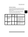
3488 Mode Differences
3488 Mode Differences
This manual describes using the Agilent 3499A/B/C in the 3488 mode of
operation. In general, the SCPI mode of operation is recommended. All
the features and functions of 3499A/B/C system and plug-in modules are
supported in SCPI mode. The 3488 mode is a subset and does not support
all available features.
4
Some of the major differences in 3488 mode of operation are summarized
below:
• The RS-232 interface is not supported in 3488 mode. You must use
the GPIB interface for remote programming.
• The 3488 mode does not provide as much control over the scanning
process as SCPI mode. You cannot use the arm and trigger layers of
scan control.
• The 3488 mode only provides access to the status byte register. You
cannot use the Standard Event or Operation Status registers.
• With firmware revision 4.0, you can store up to 40 setups (50 setups
in SCPI mode).
• Scan lists are not saved after cycling power.
• The relay cycle count feature is only available from the front-panel.
• The N2260A and N2266A can only be used in 40-channel 2-wire
mode.
• The 3488 Mode does not support the following plug-in modules:
N2272A, N2276A/B, or N2282A.
• Port numbering for Digital I/O modules is different.
57
3
Chapter 3 System Overview
Plug-in Modules Overview
Plug-in Modules Overview
The Agilent 3499A/B/C mainframes support multiple Plug-in modules,
including all the existing 3488A modules (4447XX modules), as well as
several new ones (N22XXX modules). Based on their functions, the
modules can be divided into five classes:
•
•
•
•
•
•
3
Note
Multiplexer (MUX) modules
General Purpose Relay (GP) modules
Matrix modules
Digital I/O (DIO) modules
Multifunction modules
Optical Modules
Refer to the Agilent 3499A/B/C User’s Manual (shipped with the
instrument) or visit www.agilent.com for the details of the individual
Plug-in modules.
58
Chapter 3 System Overview
Plug-in Modules Overview
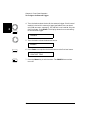
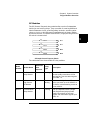
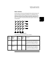
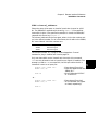
MUX Modules
A MUX (multiplexer) module switches one signal to multiple DUTs
(devices under test), or multiple signals to one device, one at a time.
Example applications include capacitor leakage, connector/switch
contact, and insulation resistance test systems. To expand switching
capacity or build special configurations, the multiplexer switching
modules can also be used with matrix or other switching modules. The
figure below shows a simple 1 x 4 Multiplexer.
4
Simple Multiplexer Switching
Multiplexers are available in several types:
•
•
•
•
One-Wire (Single-Ended) Multiplexer for common LO measurements
Two-Wire Multiplexer for floating measurements
Four-Wire Multiplexer for resistance and RTD measurements
Very High Frequency (VHF) / Microwave Multiplexer for switching
frequencies up to microwave (26.5 GHz).
The table on the next page lists the available MUX modules.
59
3
Chapter 3 System Overview
Plug-in Modules Overview
Model
Number
Module Name
Mainframe
Slots
Required
Relay
Type
Description
N2260A
40-Channel MUX
Module
1
Latching
In 3488 mode, a 40-channel 2wire multiplexer, switches both
HI and LO inputs (200 V, 1 A)
with DPST relays.
N2266A
40-Channel MUX
Module
1
Reed nonlatching
In 3488 mode, a 40-channel 2wire multiplexer.
N2268A
50Ω 3.5 GHz Dual
4-to-1 MUX
Module
1
Latching
Consists of two independent 1to-4 MUX switches which can
switch up to 30VDC or peak AC
at frequencies from DC to
3.5 GHz.
N2270A
10-Channel High
Voltage MUX
Module
2
Nonlatching
10-channel 2-wire High Voltage
MUX module with maximum
switching voltage 1000V peak
and maximum switching power
10W.
44470A/D
10/20-Channel
MUX Module
1
Latching
The 10/20 DPST (Double-pole
Single-throw) relays switch both
HI and LO inputs up to 250V,
2A with low differential offsets
for accurate measurements.
44472A
Dual 4-Channel
VHF Switch
Module
1
Latching
The two independent groups of
bidirectional 1x4 switches with
50Ω characteristic impedance
can be used for signals from
DC to 300 MHz.
44478A/B
50Ω/75Ω 1.3 GHz
Multiplexer
1
Latching
The two independent groups of
bidirectional 1x4 switches with
50Ω/75Ω characteristic
impedance can be used for
signals from DC to 1.3 GHz.
3
60
Chapter 3 System Overview
Plug-in Modules Overview
GP Modules
The GP (General Purpose) relay modules often consist of independent
latching or non-latching relays. They are useful for creating additional
isolation between circuits, providing safety interlocks, actuating other
relays or circuits, or building special topologies such as binary ladders
and tree structures. A simple 4-channel SPST (Single-pole Single-throw)
GP switch is shown below.
CH01
L
H CH01
CH02
L
H CH02
CH03
CH04
4
L
H CH03
L
H CH04
A Simple General Purpose Switch
The table below lists the available GP relay modules.
Model
Number
Module Name
Mainframe
Slots
Required
Relay
Type
Description
N2261A
40-Channel GP
Relay Module
1
Latching
The 40 independent SPST relays
provide quality connections for low
level signals. Can also switch signals
up to 200V, 1A.
N2267A
8-Channel
High Current
GP Module
1
Nonlatching
An 8-channel High Current GP module
which can switch up to 8A 250VAC or
5A 30VDC, with decreasing current to
1A at 125VDC.
44471A
10-Channel GP
Relay Module
1
Latching
The 10 independent SPST (Singlepole Single-throw) relays provide
quality connections for low level
signals. Can also switch signals up to
250V, 2A.
61
3
Chapter 3 System Overview
Plug-in Modules Overview
Model
Number
Module Name
Mainframe
Slots
Required
Relay
Type
Description
44471D
20-Channel GP
Relay Module
1
Latching
The 20 independent SPST (Singlepole Single-throw) relays provide
quality connections for low level
signals. Can also switch signals up to
250V, 1A.
44475A
Breadboard
Module
1
NA
Use the breadboard for custom circuits
and special purpose functions in your
test system.
44476A
3-Channel 18
GHz Switch
Module
1
Latching
The 3 independent 50Ω SPDT (Singlepole Double-throw) coaxial switches
with SMA connectors provide high
isolation, low insertion loss, and low
VSWR for switching signals up to
18 GHz.
44476B
2-Channel
Microwave
Switch Module
1
NA
Similar to the 44476A but does not
have the coaxial switches installed.
A variety of coaxial switches can be
mounted onto the module to provide
3-, 4-, or 5-port switching up to
26.5 GHz.
44477A
7-Channel
Form-C Relay
Module
1
Latching
7 independent, break-before-make,
SPDT Form-C relays for general
purpose switching and control of
external devices up to 250V, 2A.
3
62
Chapter 3 System Overview
Plug-in Modules Overview
Matrix Modules
A matrix switch is the most versatile type of system switching. Any input
can be connected to any output, individually or in combination. This
helps minimize the need for complex wiring, and can simplify the DUT
interface. In addition, a matrix module can be used in conjunction with
other modules to provide a wide variety of switching combinations. A
matrix is arranged in rows and columns and a simple 4 x 4 matrix switch
is shown below.
4
Matrix Switching
The table below lists the available matrix modules.
Mainframe
Slots
Required
Relay
Type
Model
Number
Module
Name
N2262A
4 x 8 Matrix
Module
1
Latching
Each crosspoint or node of the 4 x 8
matrix module uses a DPST (Doublepole Single-throw) relay to switch two
wires (Hi & Lo) for signals up to 200V,
1A.
44473A
4 x 4 Matrix
Module
1
Latching
Each crosspoint or node of the 4 x 4
matrix module uses a DPST (Doublepole Single-throw) relay to switch two
wires (Hi & Lo) for signals up to 250V,
2A.
Description
63
3
Chapter 3 System Overview
Plug-in Modules Overview
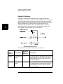
Digital I/O Modules
The digital I/O modules provide high-density digital input/output
capabilities in an easy-to-control form. The independent TTL-compatible
inputs and outputs make it well-suited for monitoring and controlling
devices compactly and cost-effectively. Typically, the digital outputs are
used to provide drive for relatively high current devices such as
solenoids, relays and small motors. The digital inputs are used to
monitor devices such as micro-switches. A simplified schematic of a
single digital input and output line is shown below.
3
OPEN COLLECTOR/
CURRENT SINK
(VMOS FET)
+ 5V
ONE I/O LINE
DRIVER OUTPUT
INPUT SENSE
REFERENCE
VOLTAGE
A Simple Digital I/O Circuit
The table below lists the available digital I/O modules.
Model
Number
Module Name
Mainframe
Slots
Required
Descriptions
N2263A
32-Bit Digital I/O
Module
1
The module offers 32-bidirectional I/O lines and
three handshake lines for sensing and control of
external devices up to 42 V, 600 mA. All lines
are TTL-compatible.
44474A
16-Bit Digital I/O
Module
1
The module offers 16-bidirectional I/O lines and
four handshake lines for sensing and control of
external devices up to 30 V, 125 mA. All lines
are TTL-compatible.
64
Chapter 3 System Overview
Plug-in Modules Overview
Multifunction Modules
A multifunction module combines two or more functions such as MUX,
GP, Matrix, Digital I/O or DAC onto a single module, making it possible
to implement a complicated switching application with fewer modules.
Therefore, the cost is reduced by minimizing the number of mainframes
and modules required.
Each separate function on a multifunction module can be operated
independently. For example, an Agilent N2265A can be used as both a 4
4 x 4 matrix module and a 16-bit digital I/O module.
The table below lists the available multifunction modules.
Model
Number
Module Name
Mainframe
Slots
Required
Relay
Type
Description
N2264A
12-Channel GP +
3-Channel Highcurrent GP +
16-Bit Digital I/O
Module
1
Nonlatching
The module provides 12-channel
SPST (Single-pole Single-throw)
GP relays for signals up to 200 V, 1
A, 3-channel high-current GP
relays for signals up to 125 V, 5 A,
and 16-bit digital I/O for sensing
and control of external devices up
to 42 V, 600 mA.
N2265A
4 x 4 Matrix +
16-Bit Digital I/O
Module
1
Latching
The module provides 4 x 4 2-wire
matrix for signals up to 200V, 1A,
and 16-bit digital I/O for sensing
and control of external devices up
to 42 V, 600 mA.
65
3
Chapter 3 System Overview
Plug-in Modules Overview
Optical Modules
The Agilent N2280A and N2281A are optical switch modules. The table
below lists the information about these three optical modules.
Model
Number
3
Module Name
Mainframe
Slots
Required
Relay
Type
Description
N2280A
Optical Switch Quad 1-to2 MUX Module
2
Nonlatching
Four 1-to-2 Optical
Switches
N2281A
Optical Switch Dual 1-to4 MUX Module
2
Nonlatching
Two 1-to-4 Optical
Switches
66
Chapter 3 System Overview
Channel and Slot Addressing
Channel and Slot Addressing
A channel refers to an individual relay on a switching module, or an
individual bit/port on a digital I/O module. The channel address is in the
form of snn, where s represents slot number and nn represents a channel
number.
For all mainframes, slot 0 refers to the 3499A/B/C control board. Valid 4
slot numbers are:
3499A
slots 0 through 5
3499B
slots 0 through 2
3499C
slots 0 through 9
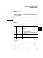
The channel number, nn, is plug-in module dependent. Detailed
information about channel numbers of individual plug-in modules is
given below and on the following pages.
Plug-in Module
Channel Addressing (snn)
s = Slot Number; nn = Channel Number
N2260A
40-Channel MUX Modulea
2-Wire Mode: s00, s01...s38, s39
N2261A
40-Channel GP Relay Module
s00, s01, s02, s03... s37, s38, s39
N2262A
4X8 Matrix Module
Row 0, 1, 2, 3; Column 0, 1, 2, 3... 6, 7
(s00, s01, s02... s07; s10, s11, s12... s17;
s20, s21, s22... s27; s30, s31, s32... s37)b
a. The N2260A and N2266A can be only be used as a 40-channel 2-wire MUX modulein 3488 mode.
b. A channel number on a matrix module is formed in Slot-Row-Column format, i.e., channel address s23 means row 2,
column 3 in Slot s.
67
3
Chapter 3 System Overview
Channel and Slot Addressing
Channel Addressing (snn)
s = Slot Number; nn = Channel Number
Plug-in Module
3
N2263A
32-Bit Digital I/O Module
Individual Bits: s00, s01, s02... s30, s31
8-Bit Ports: s00, s01, s02, s03
16-Bit Ports: s04, s05
32-Bit Port: s06
N2264A
12-Channel GP Relay +
3-Channel High-current GP Relays +
16-Bit Digital I/O Module
12 GP Relays: s00, s01, s02... s10, s11
3 High-current GP Relays: s20, s21, s22
16-Bit Digital I/O:
Individual Bits: s30, s31, s32... s44, s45
8-Bit Ports: s30, s31
16-Bit Port: s32
N2265A
4x4 Matrix +
16-Bit Digital I/O Module
4x4 Matrix:
Row 0, 1, 2, 3; Column 0, 1, 2, 3
(s00, s01, s02, s03; s10, s11, s12, s13;
s20, s21, s22, s23; s30, s31, s32, s33)a
16-Bit Digital I/O:
Individual Bits: s40, s41, s42... s54, s55
8-Bit Ports: s40, s41
16-Bit Port: s42
N2266A
40-Channel MUX Moduleb
2-Wire Mode: s00, s01...s38, s39
N2267A
8-Channel High Current GP Module
s00, s01, s02... s07
N2268A
50Ω 3.5 GHz Dual 4-to-1 MUX Module
s00, s01, s02, s03; s10, s11, s12, s13
a. A channel number on a matrix module is formed in Slot-Row-Column format, i.e., channel address s23 means row 2,
column 3 in Slot s.
b. The N2260A and N2266A can only be used as a 40-channel 2-wire MUX module in 3488 mode.
68
Chapter 3 System Overview
Channel and Slot Addressing
Plug-in Module
Channel Addressing (snn)
s = Slot Number; nn = Channel Number
N2270A
10-Channel HIgh Voltage MUX Module
s00, s01, s02... s07
N2280A
Optical Switch Quad 1-to-2 MUX Module
s00, s01; s10, s11; s20, s21; s30, s31
N2281A
Optical Switch Dual 1-to-4 MUX Module
s00, s01, s02, s03;s10, s11, s12, s13
4-Bit Built-in Digital I/O
(slot 0 control module)
Individual Bits: 091, 092, 093, 094
4-Bit Port: 090
44470A
10-Channel MUX Module
s00, s01, s02, s03... s08, s09
44470D
20-Channel MUX Module
s00, s01, s02, s03... s18, s19
44471A
10-Channel GP Relay Module
s00, s01, s02, s03... s08, s09
44471D
20-Channel GP Relay Module
s00, s01, s02, s03... s18, s19
44472A
Dual 4-Channel VHF Module
Group 0: s00, s01, s02, s03
Group 1: s10, s11, s12, s13
44473A
4x4 Matrix Module
Row: 0, 1, 2, 3; Column: 0, 1, 2, 3
(s00, s01, s02, s03; s10, s11, s12, s13;
4
s20, s21, s22, s23; s30, s31, s32, s33)a
a. A channel number on a matrix module is formed in Slot-Row-Column format, i.e., channel address s23 means row 2,
column 3 in Slot s.
69
3
Chapter 3 System Overview
Channel and Slot Addressing
Channel Addressing (snn)
s = Slot Number; nn = Channel Number
Plug-in Module
3
44474A
16-Bit Digital I/O Module
Individual Bits: s00, s01, s02... s14, s15
8-Bit Ports: s00, s01
16-Bit Port: s02
44475A
Breadboard Module
N/A
44476A
3-Channel 13 GHz Microwave
Switch Module
s00, s01, s02
44476B
2-Channel 26 GHz Microwave
Switch Module
s00, s01
44477A
7-Channel Form-C Relay Module
s00, s01, s02, s03, s04, s05, s06
44478A
50 Ω 1.3 GHz MUX Module
Group 0: s00, s01, s02, s03
Group 1: s10, s11, s12, s13
44478B
75 Ω 1.3 GHz MUX Module
Group 0: s00, s01, s02, s03
Group 1: s10, s11, s12, s13
70
Chapter 3 System Overview
Factory Default and Reset States
Factory Default and Reset States
The table on the next page shows the settings of the instrument after a
reset.
• You can reset the instrument either by pressing
Shift + Card Reset on the front-panel, or with a RESET command
over the remote interface.
4
• If a module is accidentally removed or installed while the
instrument power is on, the instrument will preform a reset.
3488 Mode Defaults
Item
Interface
GPIB/488
Factory Default
Reset
GPIB (Address 9)
Keep current settinga
RS-232b
System Mode
SCPI Mode
Keep current setting
SCPI Mode
3488A Mode
System-Related
Module-Related
Scan-Related
Keep current setting
Keep current setting
Display State
On
On
Stored State
Empty
Keep current setting
Error Queue
Empty
Cleared
Switching Channels
Open
Open
Digital I/O Ports
Input
Input
Card Pair
None
None
Scanning
None
Stop scan in progress
Scan List
Empty
Empty
Channel Delay
(seconds)
0
0
Trigger Out Pulse
Disabled
Disabled
a. Current setting includes the selection of the GPIB interface and its address setting.
b. RS-232 interface CANNOT be used in 3488A mode.
71
3
3
72
4
4
Features and Functions
Features and Functions
This chapter provides details about particular functions and features of
the Agilent 3499A/B/C Switch/Control System. The sections in this
chapter describe the features using both the front-panel and the remote
interface using SCPI commands. The examples in this chapter are
general. For specific procedures using the front panel refer to Chapter 2.
For SCPI command information refer to Chapter 5. The following
sections are included in this chapter:
4
•
•
•
•
•
•
•
•
•
Monitoring a Channel or a Slot, on page 75
Switching a Relay Channel, on page 77
Scanning, on page 78
Digital I/O Operation, on page 84
State Storage, on page 94
Error Conditions, on page 96
Self-Test, on page 96
Display Control, on page 97
Relay Cycle Counts, on page 98
The following conventions are used for the front-panel operation.
•
All keys on the front-panel keyboard are expressed in bold font and
normally associated with a “press”. For example, press Mon.
•
All the front-panel display annunciators are expressed in bold font
followed by an “annunciator”. For example, MON annunciator.
•
The information shown on the front-panel display is enclosed within a
pair of quotation marks.
•
Shift + Recall1 indicates the sequential operation: first press Shift,
then press Recall.
1
74
Also applicable to keys Card Reset, Scan, and S.List.
Chapter 4 Features and Functions
Monitoring a Channel or a Slot
Monitoring a Channel or a Slot
You may need to continuously monitor the current status of a particular
switching channel, a digital I/O port, or an entire plug-in module. This is
especially useful when developing and debugging remote interface
commands or watching for an important signal.
•
To monitor a channel or a port, specify the channel or port number.4
To monitor a plug-in module, specify the slot number. The displayed
information is module type dependent as shown on the next page.
•
Front-Panel Operation: To select a channel, a digital I/O port, or a
slot, press Mon. The MON annunciator lights up. Press Mon again
to exit this state.
MUX
O PEN
101
Monitor a switching channel 101.
D IN
255
400
Monitor a DIO Port 400.
1:0, , , , , ,6, , ,9,
2
Monitor a MUX or GP module.
00: H 255
4
Monitor a DIO module.
L254.
If only part of the channel status on the module can be displayed at
one time, press Enter to display the next part.
•
Remote Interface Operation:
OUTPUT 709; “VIEW 103”
OUTPUT 709; “VIEW 431”
OUTPUT 709; “CMON 2”
! Query the state of a relay
channel 103.
! Query the state of a bit
channel 431.
! Monitor the module in
slot 2.
75
4
Chapter 4 Features and Functions
Monitoring a Channel or a Slot
Example MON Display
1:0,,,,,,6,,,9,
2
ROW 3:,1,,3,,,6,7
3
0;,,3,COL 3,
3
00:H255
4
4
DIO
DOUT
L254.
12
090
0
091
ROW 0:,1,,3,
5
00:H255
5
L254.
76
Description
The display for a multiplexer or a GP relay module. This
display indicates that the monitored module is in Slot 2 and
channels 10, 16, and 19 are closed.
The display for a matrix module. The top display is the row
information, indicating that the relays on Row 3, Columns 1, 3,
6 and 7 of the module (in Slot 3) are closed. The lower display
is the column information, indicating that relays on column 3,
row 0 and 3 are closed.
The display for a digital I/O module. The first 2 digits on the left
(“00” in this case) represents the “L” 8-bit port address. Adding
one to this value, the “H” 8-bit port address is obtained. Data
with a trailing decimal point indicates that the last operation on
that port was a WRITE, data without a trailing decimal point
indicates that the last operation on that port was a READ. This
display shows that the data last read from Port 401 is 255 and
the data last written to Port 400 was 254.
The top display is for the built-in digital I/O Port 090 (controller
module) and the data from the last operation. The lower
display indicates that data last written to the bit channel
091 is 0.
For a multifunction module, the first function on the module is
displayed, then the next. This display is an example of a
multifunction module with matrix and DIO functions (in slot 5).
Chapter 4 Features and Functions
Switching a Relay Channel
Switching a Relay Channel
Switch modules can be used to route signals to and from your test
system. This is achieved by closing or opening the relay channels on
these modules.
•
From the front-panel, you can open or close one relay channel at a
time. However, over the GPIB interface, multiple relay channels can
4
be operated by a single command if a channel list is specified. In
addition, these open or closed states can be stored, and a stored
channel setup can be included in a scan list (see “State Storage” on
page 94).
•
Whenever a switch module is reset, all of the closed relay channels on
the module will be opened.
•
Whenever the instrument is turned on or reset, all of the closed relay
channels in the instrument will be opened.
•
Front-Panel Operation: Select a channel, press Open or Close.
Select a slot, press and hold Card Reset to open all channels on the
selected module.
Press Shift, then press and hold Card Reset to open all channels in
the instrument.
•
Remote Interface Operation: The following commands open and close
multiple channels on the modules in slots 1 and 2.
OUTPUT 709; “OPEN 101,102,207”
! Open multiple channels.
! Open all channels on the
module in slot 1.
OUTPUT 709; “CLOSE 101,102,207”
! Close multiple channels
OUTPUT 709; “CRESET 1”
77
4
Chapter 4 Features and Functions
Scanning
Scanning
The Agilent 3499A/B/C can scan switching channels, digital I/O bit
channels, and stored channel setups in a scan list. When a scan starts,
the first channel in a scan list is closed. The channel is then opened and
the next channel in the list is closed. This process repeats for all
channels in the scan list. You can sweep through a scan list more than
once. You can also synchronize scanned channel closures with external
measurement devices.
Rules for Scanning
•
A scan list must be specified before initiating a scan. One or more
switching channels, digital I/O bit channels, and/or previously stored
channel setups can be included in a scan list. The order of the
channels in the scan list determines the order of the channels to be
scanned.
•
If any plug-in module is installed or removed while the instrument is
operating, the instrument will automatically perform a reset and the
current scan list is cleared.
•
If a scan list contains a non-existing channel, the scan cannot be
performed and an error will occur.
•
If a scan list contains a channel on a digital I/O module that is not
configured to handshake mode #1 or mode #2 (see page 86), the scan
cannot be performed and an error will occur.
•
If a mismatch between a stored channel setup in the scan list and the
current hardware configuration is found, a scan cannot be performed
and an error will occur. When a stored setup is included in the scan
list, the stored setup is recalled and the next channel in the scan list
is switched.
•
When a scan is aborted, the channel last scanned before the
interruption will remain closed. Aborting a scan does not affect the
present scan configuration. A scan cannot resume from where it is
interrupted. To initiate a new scan, the channels in the scan list will
be scanned from the beginning of the scan list.
•
A scan list may contain up to 200 entries.
4
78
Chapter 4 Features and Functions
Scanning
Creating a Scan List
Before initiating a scan, a scan list must be set up. The instrument scans
the specified channels automatically in the same order of the scan list.
•
The scan list is automatically cleared whenever the instrument is
turned off or reset. You can also clear the scan list by pressing
Shift+S.List.
•
Front-Panel Operation: Press S.List, the CONFIG annunciator will4
light. The display will show “ADD TO SCAN”. Press Enter to begin
building the scan list. Select each desired channel and press Enter to
add the channel to the scan list. As channels are added, an asterisk is
shown in the display to indicate the channel is a part of the scan list.
SELECT
SELECT
SELECT
•
*
101
Select a channel to add.
101
Press Enter.
203
Select the next channel to add.
Remote Interface Operation: You may use single channels, ranges of
channel, or stored setups in the scan list. Set up a scan list with one
command as follows:
10
20
30
40
50
Note
4
Press S.List. Press Enter.
ADD TO SCAN
OUTPUT 709; “SLIST 100-109 “! Create a scan list.
FOR I = 1 to 10
OUTPUT 709; “STEP”
! Step through the scan list.
OUTPUT 709; “DELAY 20”
! Add 20 ms time delay.
Next I
Stored states may be used in scan lists. Stored states are discussed in
more detail beginning on page 94.
79
Chapter 4 Features and Functions
Scanning
Configuring a Scan
You can use delay times to control a scan.
•
You can specify a delay time (from 0 to 99999.999 seconds, with 1 ms
resolution) between when a channel is closed and when the next
operation begins (and, if configured, a trigger out pulse is sent). The
delay time can be set individually for each channel in the scan list, or
one delay can be set for all channels in the scan list. Note that, even if
the trigger source is set to IMMediate, the scan list will not advance
until the delay time is met.
•
Front-Panel Operation: Use the S.List menu to set the scan delay
time as shown below.
4
•
DELAY TIME
Turn the knob to select DELAY TIME.
Press Enter.
00000.0000 SECS
Use arrow keys and knob to
select the delay time. Press Enter.
3499
Press S.List to exit the menu.
Remote Interface Operation:
OUTPUT 709; “DELAY 2000; CHAN 101”
! Set a 2 second delay time
80
Chapter 4 Features and Functions
Scanning
Performing a Scan
Once you set up a scan list and configure the scan, the actual scan can be
performed.
•
If a scan list contains a non-existing channel, the scan cannot be
performed and an error will occur.
•
If a scan list contains a channel on a digital I/O module that does not
work in Mode #1 or Mode #2, the scan cannot be performed and an 4
error will occur (see page 86 for more information about modes).
•
If a stored channel setup in the scan list does not match the current
hardware configuration, the scan cannot be performed and an error
will occur.
•
Front-Panel Operation: Press Scan to begin the scan operation.
4
Stop a scan in progress by pressing Shift+Scan. The last channel
closed in the scan list will remain closed. You cannot pause and then
continue a scan. You must start the scan operation over.
Press Step to start and step through the channels in the scan list, one
channel at a time.
•
Remote Interface Operation: Use the STEP command to begin a scan.
If you abort a scan in progress, the last channel closed in the scan list
will remain closed. You cannot pause and then continue a scan. You
must start the scan operation over.
OUTPUT 709; “STEP”
!Step into the scan list.
81
Chapter 4 Features and Functions
Scanning
Using External Triggering
Two control lines are provided in the rear panel mini-DIN connector:
external trigger in and external trigger out. These lines can be used
individually or combined to synchronize a scan list with an external
instrument (such as a DMM). The figure below shows this connection.
The 3499A/B/C can be configured to output a trigger pulse to notify the
external instrument whenever a channel is closed.
Agilent 3499B
External DMM
4
1
3
2 4
VM Complete Out
Ext Trig In
5
8 (Ext.Trig.Out)
6
7
(Ext.Trig.In)
•
In addition to the Ext.Trig.In and Ext.Trig.Out pair provided on the
rear panel of the mainframe, the EI (external increment) and CC
(channel closed) pair on a 44474A module can also be used to
synchronize. Specify either Slot 0 or the slot in which a 44474A
module is installed to indicate which lines are to be used.
•
Both the built-in trigger lines and the EI/CC lines on the 44474A are
TTL compatible.
•
Once enabled, the selected trigger-in line is immediately ready to
accept the trigger signal from the external instrument. Enabling or
disabling a trigger source from the front-panel sets both the trigger in
and trigger out functions.
82
Chapter 4 Features and Functions
Scanning
•
Front-Panel Operation: Press Menu, use the knob to select
“CONF EXT TRIG” and press Enter. Select either slot 0 (built-in
external trigger) or the slot where a 44474A is installed and press
Enter. Enable or disable the pair of trigger lines and press Enter.
Press the Menu key again to exit the menu.
Press S.List, select “CONFIG SCAN”, and configure the arm source
or trigger source as either EXT or MIX.
•
Remote Interface Operation: The following code segment will set up
the 3499A/B/C to synchronize with an external instrument.
OUTPUT 709; “DMODE 0,1,0,1”
4
! Enable a trigger pulse on the
rear panel Mini DIN
connector.
4
83
Chapter 4 Features and Functions
Digital I/O Operation
Digital I/O Operation
The digital input/output is well-suited for monitoring and controlling
external devices. You may use the built-in digital I/O bits or port (on the
rear panel), one or more digital I/O modules, or a multifunction modules
with a DIO function. In the following context, multifunction modules
refer to those with a DIO function.
•
The built-in digital I/O (control board) consists of four bits which can
be operated either independently as four bit channels (numbered 091
through 094) or as one 4-bit port (numbered 090).
•
The plug-in digital I/O modules and multifunction modules usually
consist of several 8-, 16-, and/or 32-bit ports. These ports can be
operated independently, which means one port can be used for output
operation, while others can be used for input. However, all bits within
a same 8-bit port are dependent. If one bit of a port is used for input
or output operation, then all other bits of the same port can only be
used for the same operation.
4
Note
For more information about a specific digital I/O module, refer to the
Agilent 3499A/B/C User’s Manual (shipped with the instrument) or visit
www.agilent.com.
Digital I/O Configuration
•
Parameters such as flow control mode, control line polarity (PCTL),
flag line polarity (PFLG), and I/O direction line polarity, are all
configured for the plug-in digital I/O modules and multifunction
modules. However, these DO NOT apply to the built-in 4-bit
digital I/O (on the rear panel).
•
The data line polarity of any 8-bit port (or the 4-bit built-in port) can
be configured from the front-panel. However, using the remote
interface, the data line polarity of any ports (8-, 16-, or 32-bit) can be
configured.
•
Data display format of any 8-bit port, binary or decimal (default), can
only be specified from the front-panel. Once specified, the format
applies to all input and output operations on the same port.
•
When the instrument is turned on or reset, the handshake mode is
set to Mode #1 and the polarities of all configured lines are positive.
More information about handshake modes is given starting on
page 86.
84
Chapter 4 Features and Functions
Digital I/O Operation
•
Note
Front-Panel Operation: Select a digital I/O module and press Mode.
“CONFIG DIO” is shown in the display. Press Enter to show the
second-level menu and begin the configuration.
Be sure to select the module, not a port or bit. The options on this menu
are only available when the module is selected.
4
Select a DIO module.
N 2263A
4
CONFIG DIO
4
MODE 1
4
Select flow control mode. Press Enter.
C O NT P O L P O S
4
Select the control line polarity. Press Enter.
FLA G P O L P O S
4
Select the flag line polarity. Press Enter.
I/O P O L P O S
4
Select the I/O direction line polarity. Press Enter.
Press Mode.
4
Press Mode again to exit the menu.
Configure a port. Select a digital I/O port, then press Mode, the
CONFIG annunciator lights up. When “DATA POLARITY” appears
in the display, press Enter to set data line polarity and/or use the
knob to select “DISP FORMAT” and press Enter to set data display
format for the port.
DIN
401
DATA POLARITY
NEG POLARITY
or
DIN
401
401
DISP FORMAT
401
401
BINARY
401
85
Chapter 4 Features and Functions
Digital I/O Operation
•
Remote Interface Operation: Set the flow control parameters using the
following 3488 command. This example assume a digital I/O module
is installed in slot 4.
OUTPUT 709; “DMODE 4,1,0,1”
! Set the flow control to Mode
#1 and the polarity of all
lines to default values.
About Flow Control Modes (Handshake)
Five flow control modes are available for Digital I/O operations. Some
modes use one or more of the three flow control lines: I/O Direction,
PFLG, and PCTL. Select the flow control you need for your digital input/
output applications.
4
Note
The polarity of the flow control lines is assumed to be positive (the
default) in the following diagrams and discussions.
Handshake
Mode
Mode
Number
Definition
86
Notes
1
Static mode #1
Default handshake mode.
2
Static mode #2
Read what was written.
3
Read or Write
and strobe
If you set a port to this mode, you cannot use
the port in a scan list.
4
Read and write
strobe
If you set a port to this mode, you cannot use
the port in a scan list.
5
Full handshake
If you set a port to this mode, you cannot use
the port in a scan list.
Chapter 4 Features and Functions
Digital I/O Operation
Static Mode #1
Static Mode #1 is the default mode. In this mode, data is transferred
statically, there is no read or write strobe pulses or handshaking. The I/O
Direction line is active and indicates direction of transfer. This is shown
in the following timing diagrams.
Write Operation
(CLOSE, DWRITE, etc.)
DATA LINES
DATA VALID
4
t1 = I/O in p u t to d at a
v a lid (1 m s m in im u m )
I/O DIRECTION
t1 (>1ms)
4
Approximately 1 ms after the I/O direction line goes to a low
state, the digital I/O module takes control of the data lines.
Read Operation
(DREAD, etc.)
DATA LINES
DATA VALID
I/O DIRECTION
t1
100µs
t2
150µs
t1 = D a ta b u s floa te d
to I /O in p u t
1 0 0( µs m in im u m )
t2 = I/O in p u t to d a ta
la tc h e d (1 5 0 µs
m in im u m )
100 µs after the 3499A/B/C is instructed to read the data lines, it releases
control of the lines and the I/O direction line goes to a high state. 150 µs
later the data is actually read (latched).
Static Mode #2
Static Mode #2 acts just like Mode #1 except the output lines are not
disabled during an input operation. This means that if a port is written
to and then read from, the data read will be that which was just written
to it. It is possible, however, that external devices might load the lines
and cause a false read.
Timing for the I/O direction line is as shown in Mode #1 for write
operations. For read operations, the I/O direction line does not change.
87
Chapter 4 Features and Functions
Digital I/O Operation
Read or Write and Strobe Mode #3
In this mode, the I/O direction line is still used to indicate direction of
transfer (input or output) but the PCTL (Peripheral control) line is used
to strobe the data.
During a write operation, where the 3499A/B/C writes the data to some
external device, the strobe pulse signifies that the data on the 16 or 32
data I/O lines is valid. This is shown in the following timing diagram.
DATA LINES
DATA VALID
W rite O peration
I/O DIRECTION
t 2 = T im e fr om ou tp u t
e n a b le t o st a rt of
t robse (2 5 µs
m in im u m )
STROBE (PCTL LINE)
4
t 1 = T im e fr om I/O lin e
low to ou tp u t e n a b le
(1 m s m in im u m )
t1
1ms
t2
25 µs
t3
20 µs
t 3 = S tr ob e p u lse w id th
(2 0 µs m in im u m )
A S trobe pu lse sig nifies that the data on th e data lines is valid. D u ring a
w rite operation , the dev ice receiving the da ta is trig gered by the strobe.
The Strobe pulse is used during a read operation to signify that the
3499A/B/C has completed the read operation. This is shown in the
following diagram.
DATA VALID
DATA LINES
R ea d O p era tion
I/O DIRECTION
STROBE (PCTL LINE)
t1
100 µs
t2
150 µs
t3
20 µs
t 1 = T im e fr om ou tp u t
d isa b le to I/O lin e
h ig h (1 0 0 µs m in )
t 2 = T im e fr om I/O lin e
h ig h to sta r t of
S tro b e (1 5 0 µs
m in im u m )
t 3 = S tr ob e p u lse w id th
(2 0 µs m in im u m )
When used during a Read operation, the Strobe pulse signifies that the
3499A/B/C has latched (read) the data from the data lines.
88
Chapter 4 Features and Functions
Digital I/O Operation
Read and Write Strobe Mode #4
Read and Write Strobe Mode #4 uses the I/O direction line as a Strobe
pulse to indicate writing operations. The PCTL line is used to indicate
Read operations. It is thus similar to the R/W and Strobe Mode #3 except
separate control lines are used for the Strobe pulses and there is no I/O
direction line.
DATA LINES
4
DATA VALID
W rite O peration
t 1 = T im e fr om d a t a
v a lid to w r ite
S tr ob e
(4 0 µs m in im u m )
IO DIRECTION (WR)
t1
40 µs
t2
20 µs
t 2 = S tro b e p u lse w id th
(2 0 µs m in im u m )
The IO Direction line is used to indicate that the data is valid on the data bus lines.
IO Direction is used to trigger the receiving device.
DATA VALID
DATA LINES
R ea d O p era tion
PCTL (RD) LINE
t1
100 µs
t2
20 µs
t1 = T im e from o u tp u t
d isa b le to rea d
S tr ob e (1 0 0 µs
m in im u m )
t 2 = S tr ob e p u lse w id th
(2 0 µs m in im u m )
As in Mode #3, the PCTL (RD) line is used to indicate to the sending
device that the 3499A/B/C has latched (read) the data.
89
4
Chapter 4 Features and Functions
Digital I/O Operation
Full Handshake Mode #5
Handshake Mode #5 provides a complete two wire handshake with a
data direction line. During write operations, the PCTL line indicates that
output data is valid; during read operations, it indicates that the digital
I/O module (i.e. N2263A) is “ready for data”. The PFLG line is used by
the peripheral device to indicate “ready for data” during write operations
or “data valid” for read operations.
For this discussion, write operations mean the plug-in digital I/O module
is controlling the data lines. Read operations mean external devices
control the data lines and the digital I/O module reads the data and
controls the PCTL/RD line.
4
t 1 = T im e fr om I/O lin e
low to ch eck for
P F L G low
(1 ms minimum)
W rite O p era tion
DATA LINES
DATA VALID
t2 = T im e fro m P F L G
lo w to d a ta v a lid
(4 0 µs m in im u m )
I/O DIRECTION
t3 = T im e from d a ta v a lid
to P C T L lo w
(3 0 µs m in im u m )
PCTL LINE
t4 = T im e from P C T L lo w
to c h e ck for P F L G
h ig h (4 0 µs m in im u m )
PFLG LINE
t1
1 ms
t2
40 µs
t3
30 µs
t4
40 µs
t5
35 µs
t5 = T im e from P F L G
to P C T L h igh
(3 5 µs m in im u m )
The complete handshaking sequence for Mode #5 is as follows: The 3499A/B/C checks
to see if the receiving device has set the PFLG line low, this indicates the receiving
device is ready to accept data. When PFLG is low, the 3499A/B/C sets the data on the
data bus and sets PCTL low. The 3499A/B/C then waits for the receiving device to set
PFLG high, indicating that it has latched the data. To complete the handshake, the
3499A/B/C sets PCTL high.
90
Chapter 4 Features and Functions
Digital I/O Operation
R ea d O peration
DATA VALID
LATCHED
DATA LINES
I/O DIRECTION
t1 = T im e fro m ou tp u t
d isa b le to I/O lin e
h ig h (1 0 0 µs m in im u m )
t2 = T im e fro m I/O lin e
h igh to ch eck for
P F L G lo w
(4 5 µs m in im u m )
t3 = T im e fro m P F L G low
to ch eck fo r P C T L
lo w (5 0 µs m in im u m )
PCTL LINE
PFLG LINE
4
t4 = T im e fro m P C T L low
to ch eck P F L G
h ig h (4 0 µs m in im u m )
t1
100 µs
t2
45 µs
t3
t4
t5
50 µs 40 µs 35 µs
t5 = T im e fro m P F L G
h ig h t o P C T L h igh
a n d d a ta la tch ed
(3 5 µs m in im u m )
4
As with the Write operation, the 3499A/B/C begins by testing PFLG for a
low state, indicating that the data is valid. When PFLG is low, the
3499A/B/C sets PCTL low and waits for PFLG to go high. The 3499A/B/C
will set PCTL high to indicate that it has completed the data read operation.
Data on the data bus must remain valid until after the 3499A/B/C sets
PCTL high.
91
Chapter 4 Features and Functions
Digital I/O Operation
Digital Input Operation
4
•
From the front-panel, you can read data from the built-in digital I/O
bits/port (numbered 090 through 094) or any one of the 8-bit ports on
a digital I/O module or multifunction module.
•
From the remote interface, you can read data from the individual bit
channels and 8-, 16-, or 32-bit ports on a digital I/O module or
multifunction module, as well as from the built-in digital I/O bits/port
(numbered 090 through 094).
•
Instrument reset will set all digital I/O ports in the instrument as
input ports. Pressing Card Reset or issuing a RESET command will
set all ports on the specified module as input ports (ports on other
modules are not affected).
•
Front-Panel Operation: Select an 8-bit digital I/O port, press Read to
read the data from the port. The data can be displayed as either
decimal or binary (see page 33).
•
Remote Interface Operation: Use the following command to read an
individual bit (bit 6) on a module in slot 4. A “0” (bit cleared) or a “1”
(bit set) will be returned.
OUTPUT 709; “DREAD 402”
OUTPUT 709; “VIEW 403”
! Read data from Port 402.
! View a bit channel 4.
The range of possible returned values is shown:
Parameter
Decimal Range
Hex range
BYTE
0 to 255
00h to FFh
WORD
-32768 to 32767
-8000h to 7FFF h
LWORD
-231 to (231 -1)
-80000000h to 7FFFFFFFh
WORD values greater then 32767 and LWORD values greater then
for (231 -1) are returned as negative numbers. These values are in 2’s
complement form.
92
Chapter 4 Features and Functions
Digital I/O Operation
Digital Output Operation
•
From the front-panel, you can write data to the built-in digital I/O
bits/port (numbered 090 through 094) or any one of the 8-bit ports on
a digital I/O module or multifunction module.
•
From the remote interface, you can write data to individual bit
channels and 8-, 16-, or 32-bit ports on a digital I/O module or
multifunction module, as well as to the built-in digital I/O bits/port
4
(numbered 090 through 094).
•
Instrument reset will set all digital I/O ports in the instrument as
input ports. Pressing Card Reset or issuing a RESET command will
set all ports on the specified module as input ports (ports on other
modules are not affected).
•
Front-Panel Operation: Select an 8-bit port, press Write, the data
from the last operation (read or write) will be displayed. Edit the data
to the desired value and press Enter to write the data to the port. To
cancel the write operation, press Write again instead of Enter. You
can edit the data in either binary or decimal form (see page 33).
•
Remote Interface Operation:
OUTPUT 709; “DWRITE 400,219” ! Write 219 to 16-bit Port 404.
OUTPUT 709; “CLOSE 401,407,411”
! Close bit channels 401, 407,
and 411.
OUTPUT 709; “OPEN 403,405,407”
! Open bit channels 403, 405,
and 407.
WORD values greater then 32767 and LWORD values greater then
for (231 -1) are sent as negative numbers. These values are in 2’s
complement form.
93
4
Chapter 4 Features and Functions
State Storage
State Storage
The 3499A/B/C provides the capability to store setups, and then recall
them to put the instrument back into a known configuration.
Information that can be stored includes:
•
•
•
Status of all relay channels (open or closed)
Status of digital I/O ports (input or output, flow control, etc.)
Remote interface settings (address, baud, etc.)
Additionally, you can include a stored state in a scan list as a channel.
4
Firmware Revision Differences
State storage behavior differs depending upon the firmware revision of
your 3499A/B/C (see page 55).
•
Firmware revision 1.0 must be upgraded. Please contact your nearest
Agilent Technologies Office for details.
•
Firmware revisions 2.0 and 3.0 allow up to 10 states to be stored.
Firmware revision 4.0 allows up to 40 stored states.
•
Stored states are lost if power is removed for firware revisions 2.0 or
3.0. Stored states are preserved when power is removed for firmware
revision 4.0.
•
Storage memory locations are numbered 01 to 10 for Firmware
revision 2.0 and 3.0. Memory locations are number 01 to 40 for
Firmware revision 4.0.
•
Before recalling a stored setup, the instrument verifies that all
module types and slot assignment match the setup. If a mismatch is
detected, an error (“RECALL FAILED”) will occur.
94
Chapter 4 Features and Functions
State Storage
Firmware Revision Differences (continued)
•
An instrument reset does not affect the stored instrument setup
information.
•
All stored setups will be cleared if the system mode is changed (for
example, to SCPI mode).
•
Firmware revision 3.0 allows instrument operation in either SCPI or
3488 mode, not both. The mode is selected when the firmware is
4
loaded.
To Store an Instrument State
Firmware revision 2.0 and 3.0 allow up to 10 stored states. Firmware
revision 4.0 allows up to 40 stored states. Set the instrument to the state
you want to store.
•
Front-Panel Operation: To store an instrument setup, press
Shift + Recall, select a memory location, and press Enter. To cancel
the store operation, press Recall again instead of Enter.
•
Remote Interface Operation:
OUTPUT 709; “STORE 4”
Note
! Store an instrument setup
Approximately 1 second is required to store an instrument setup into an
Agilent 3499A/B/C with Firmware REV 4.0. To avoid errors in when
programming, be sure to allow a 1 second interval between the store and
recall operations.
To Recall an Instrument State
You can recall a previously stored instrument setup.
•
Front-Panel Operation: To recall a stored setup, press Recall, select
the memory location to be recalled, and press Enter. To cancel the
recall operation, press Recall again instead of Enter.
•
Remote Interface Operation:
OUTPUT 709; “RECALL 4”
! Recall the previously stored
channel setup.
95
4
Chapter 4 Features and Functions
Error Conditions
Error Conditions
When an error occurs, the 3499A/B/C will beep and the ERROR
annunciator on the front-panel lights up. This indicates one or more
command syntax or hardware errors have been detected.
4
•
The error queue will be cleared automatically once you read the
queue, change the system mode, send the RESET command, or cycle
power on the instrument. However, a module reset will not clear the
error queue.
•
Front-Panel Operation: Press View, select “ERROR”, and press
Enter. The sum of the values of the possible error conditions is
displayed (refer to “Error Messages” on page 135).
•
Remote Interface Operation: In 3488 mode, the sum of the values of
the possible error conditions is recorded in the error queue. For
example, the returned value of “0003” means that both “Syntax
Error” and “Execution Error” occurred (refer to “Error Messages” on
page 135).
ERROR
! Query the error register.
Self-Test
The 3499A/B/C can perform a self-test to verify that it is in proper
operation.
•
If the self-test is successful, “PASSED” will be displayed on the frontpanel. Otherwise, the reason of the failure will be displayed. For
details of all self-test failures, refer to “Self Test Errors” on page 136.
•
Front-Panel Operation: Press Menu, use the knob to select
“SELFTEST”, and press Enter to perform a self-test.
•
Remote Interface Operation:
TEST
96
! Returns zero if the test is
successful, or non-zero if it
fails.
Chapter 4 Features and Functions
Display Control
Display Control
You can turn off the 3499A/B/C display (for security or increased
processing speed for example). You can also write a message of up to 13
characters to the front-panel display.
Note
The display cannot be turned off from the front-panel.
4
•
When the display is turned off, the entire front-panel display goes
blank except for the ADRS and RMT annunciators (the ERROR
annunciator will also be on if there are errors), and all keys except
Local are locked.
•
If the display is turned off, pressing Local causes the instrument to
return to local operation, the display will be turned back on.
•
The display is automatically turned on when power is cycled, or after
a RESET command.
•
When the display is on, you can send a message (up to 13 characters)
to display on the front-panel from the remote interface. If you attempt
to send more than 13 characters, only the first 13 characters can be
displayed. The characters can be letters (A-Z), numbers (0-9), and
some special characters (“ ‘ space ( ) * + - , . : ; / \).
•
Remote Interface Operation:
OUTPUT 709; “DOFF”
! Turn off the display.
OUTPUT 709; “DON”
! Turn on the display.
OUTPUT 709; “DISP Scan finished.”
! Display the message on the
front panel.
97
4
Chapter 4 Features and Functions
Relay Cycle Counts
Relay Cycle Counts
The Agilent 3499A/B/C can read and track the relay cycle counts on some
plug-in modules. This feature can be very useful in switching systems to
track relay failures and predict system maintenance requirements.
•
This feature is supported in 3488 Mode by the Agilent N2260A,
N2261A, N2262A, N2264A, N2265A, N2266A, N2267A, N2268A,
N2270A, and N2280A/81A modules.
•
The cycle counts of the tree relays (s98 & s99) on an N2260A or
N2266A can also be queried.
•
Front-Panel Operation: Press View, use the knob to select “RELAY
CYCLES”, and press Enter. Turn the knob to select the relay channel
of interest. The display shows the channel cycle count.
•
Remote Interface Operation: This feature is only available from the
front panel in 3488 mode.
4
98
5
5
Remote Interface Reference
Remote Interface Reference
This chapter describes 3488 mode commands applicable to the Agilent
3499A/B/C Switch/Control System. The chapter contents include:
•
•
•
Note
Command Syntax, on page 101
3488 Mode Command Quick Reference, on page 102
3488 Mode Commands, on page 104
It is highly recommended that you use SCPI commands (in SCPI mode)
instead of 3488A commands (in 3488A mode). The SCPI commands allow
you to use all the features of the Agilent 3499A/B/C and the plug-in
modules. 3488 mode commands are a subset and are provided for legacy
installations.
5
100
Chapter 5 Remote Interface Reference
Command Syntax
Command Syntax
Throughout this manual, the following conventions are used for
command syntax for remote interface programming.
•
•
•
Square brackets ([ ]) indicate optional keywords or parameters.
•
A vertical bar ( | ) separates multiple parameters.
Braces ({ }) enclose parameter choices within a command string.
4
Angle brackets (< >) enclose parameters for which you must specify a
value.
Rules for Using a Channel or Scan List
Many of the SCPI commands include a channel list or scan list
parameter which allows you to specify one or more channels. The
channel number has the form (@snn), where s is the slot number and nn
is the channel number. You can specify a slot, a single channel, or
multiple channels as described below.
•
The following command closes a single channel (channel 11) on the
module installed in slot 1:
OPEN 111
•
The following command closes multiple channels on modules in slots
1 and 2:
CLOSE 111,112,203,204
•
Additional information about channel and slot numbering is given on
page 67.
101
5
Chapter 5 Remote Interface Reference
3488 Mode Command Quick Reference
3488 Mode Command Quick Reference
Command Summary
5
Command
Description
Page
CHAN
Open the last channel/bit closed and close the specified channel/bit.
104
CLOSE
Close one or more relays (channels/bits) on the plug-in modules.
105
CMON
Monitor the open/close states of a plug-in module in the specified slot.
106
CRESET
Reset one or multiple cards in the specified slot(s) to their default states.
106
CPAIR
Pair up two plug-in modules of the same type.
107
CTYPE
Query the module’s identification in the specific slot.
108
DBR
Read digital I/O port.
110
DBW
Output a block of binary data to the specified digital I/O port.
112
DELAY
Insert a delay time during scanning.
113
DISP
Write a message to display.
114
DMODE
Establish the handshake mode, polarity and trigger configuration of the
DIO module.
115
DOFF
Turn off the front panel display of the instrument.
117
DON
Turn on the front panel display of the instrument.
117
DREAD
Read the status of a digital I/O port as inputs.
118
DWRITE
Output a block of data to the specified digital I/O port.
120
EHALT
Enable/Disable the stop-on-error mode.
121
ERROR
Query Error register.
121
ID?
Query the instrument’s identity.
121
LOCK
Activate or deactivate locking out the keyboard of the instrument.
122
102
Chapter 5 Remote Interface Reference
3488 Mode Command Quick Reference
Command
Description
Page
MASK
Query/set the SRQ mask conditions.
122
OLAP
Enable/Disable GPIB I/O overlap mode.
123
OPEN
Open one or more relays (channels/bits) on the plug-in modules.
124
RECALL
Re-assert the channel/bit setup stored by the command STORE (1-10).
125
RESET
Reset the instrument to its power on state. All channels/bits of the plug-in
modules are open, etc.
125
SLIST
Specify a sequence of channels/bits to be scanned.
126
SYSMODE
Specify a system mode (SCPI or 3488A) for the instrument.
127
SYSMODE?
Query the instrument’s system mode.
127
SREAD
Read back the read-only port on a 44475A Breadboard module
(for 44475A only).
128
SWRITE
Write data to the static write-only port on a 44475A Breadboard module
(for 44475A only).
129
STATUS
Query the Status Byte of the 3499A/B/C.
130
STEP
Sequence through a scan list set up by SLIST.
131
STORE
Store the current of the instrument in the specified register number (1-10).
131
TEST
Cause the 3499A/B/C to perform an internal self-test.
132
VIEW
Query the state of a particular channel/bit.
133
4
5
Command Summary
103
Chapter 5 Remote Interface Reference
3488 Mode Commands
3488 Mode Commands
CHAN [<channel_address>]
Opens the last channel/bit closed by either STEP or CHAN command
and then closes the specified channel/bit.
The channel_address has the form @snn, where s is the slot number and
nn is the channel number. For all mainframes, slot 0 refers to the 3499A/
B/C control board. Valid slot numbers are:
3499A
slots 0 through 5
3499B
slots 0 through 2
3499C
slots 0 through 9
The channel number, nn, is plug-in module dependent. Channel
numbers for plug-in modules are listed on page 70.
5
If no channel/bit is specified with CHAN, the 3499A/B/C will respond with
the number of the last channel closed. If no channel has been closed since
the last reset, then CHAN returns the number 0.
If a Scan List is in effect when CHAN is executed, the 3499A/B/C will
search through the list and position the Scan List pointer to the channel
specified by CHAN. If CHAN specifies a channel that is not in the Scan List,
and then STEP is executed, the 3499A/B/C will open the channel closed
by CHAN and go to the beginning of the Scan List.
OUTPUT 709; “CHAN 203”
OUTPUT 709; “CHAN
ENTER 709; A
DISP A
104
! Close channel 203.
Chapter 5 Remote Interface Reference
3488 Mode Commands
CLOSE <channel_address>[,<channel_address>,<channel_address>...]
Close one or more channels on the non digital I/O (DIO) modules. It can
also be used to “clear” bits on the digital I/O modules. The CLOSE
command does not open any channels/bits that were previously closed.
The channel_address has the form @snn, where s is the slot number and
nn is the channel number. For all mainframes, slot 0 refers to the 3499A/
B/C control board. Valid slot numbers are:
3499A
slots 0 through 5
3499B
slots 0 through 2
3499C
slots 0 through 9
4
The channel number, nn, is plug-in module dependent. Channel
numbers for plug-in modules are listed on page 70.
Several channels or bits can be closed with one CLOSE command by
separating the channel or bit addresses with a comma. If more than one
channel or bit is specified, they are closed or bits “cleared” in the order
listed.
When CLOSE is used with the DIO modules (44474A, N2263A, N2264A,
N2265A), the DIO modules must be in either default Static Mode #1 or
Static Mode #2. Using the CLOSE command in any other mode will cause
an error. In these modes there is no read or write handshaking. Digital
modes are described in more detail on page 86.
The bits 091-094 on the 4-bit built-in digital I/O can be also included in
the channel_address.
All the channels/bits in the plug-in modules are opened following a reset.
For the DIO modules, all bits are operating as input bits, no
handshaking enabled.
OUTPUT 709; “CLOSE 102,103,212,313”
! Close the specific channels.
105
5
Chapter 5 Remote Interface Reference
3488 Mode Commands
CMON <slot>
Causes the 3499A/B/C to monitor the individual card (module) in the
specified slot.
The slot parameter is a decimal ranging from 0 to 9 (mainframe
dependent). Valid slot numbers are:
3499A
slots 0 through 5
3499B
slots 0 through 2
3499C
slots 0 through 9
Specifying 0 as the slot number turns off the monitor function. Cycling
power on the instrument or resetting the modules will cancel the
monitoring.
You cannot monitor the 4-bit built-in DIO, an individual DIO port, or a
switching channel.
The displayed information is module dependent, refer to page 75 for
more details.
OUTPUT 709; “CMON 2”
ENTER 709; A$
DISP A$
5
CRESET <slot>[,<slot>...]
Resets all channels/bits on the specified modules to their open state.
Only the modules in the specified slots are affected.
The slot parameter is a decimal ranging from 0 to 9 (mainframe
dependent). Valid slot numbers are:
3499A
slots 0 through 5
3499B
slots 0 through 2
3499C
slots 0 through 9
Switching Modules: All the switching channels on the specific module
are reset to their open state.
DIO Modules: A digital I/O module is reset to its default mode. That
means the bits on the module are set to open (high impedance), and the
module is in the Static Mode #1 (no handshaking).
OUTPUT 709; “CRESET 2”
106
! Reset the module in slot 2.
Chapter 5 Remote Interface Reference
3488 Mode Commands
CPAIR <slot>,<slot>
Pairs two of the same (type) plug-in modules (i.e. two N2261A modules).
This operation will effectively assign both modules to both slot numbers
so that closing/opening/scanning a channel on either one module will
perform the same operation on the respective channel on the other
module.
The slot parameter is a decimal ranging from 0 to 9 (mainframe
dependent). Valid slot numbers are:
3499A
slots 0 through 5
3499B
slots 0 through 2
3499C
slots 0 through 9
4
This feature is especially useful when doing 4-wire scanning with the
MUX modules, such as 44470A/D, N2260A, etc.
Commands used with the CPAIR function are: CLOSE, OPEN, CRESET,
CHAN, STEP, DWRITE and DREAD. Channels/bits on the paired slots can be
included in a scan list.
Executing a CPAIR command cancels any previous CPAIR command that
involved either of the two modules. It is possible, however, to have two
sets of card pairs, e.g. Slot 1 paired with 2 and Slot 3 paired with 4.
Paired DIO Modules: Two of the same (type) DIO modules used in
Mode #1 or #2 can be paired. You cannot pair DIO modules using other
handshake modes (see page 86).
Executing the CPAIR command without specifying slot numbers allows
you to determine which, if any, slots are paired together. Four numbers
are returned separated by commas. The first two numbers specify slots
in the first pair, the second two numbers specify the second pair. An
inactive card pair is denoted by 0,0.
OUTPUT 709; “CPAIR 1,3”
OUTPUT 709; “CLOSE 105”
! Pair the modules in Slot 1
and Slot 3.
! Close Channels 105 and 305
simultaneously.
107
5
Chapter 5 Remote Interface Reference
3488 Mode Commands
CTYPE <slot>
This query returns a string containing the module identification in the
specified slot. The slot parameter is a decimal ranging from 0 to 9
(mainframe dependent). Valid slot numbers are:
3499A
slots 0 through 5
3499B
slots 0 through 2
3499C
slots 0 through 9
OUTPUT 709; “CTYPE 3”
ENTER 709;A$
DISP A$
5
108
! Look for the card in Slot 3.
! Card description will be
displayed.
Chapter 5 Remote Interface Reference
3488 Mode Commands
The string returned has one of the following forms:
Module
Returned String
Empty Slot
Mainframe
N2260A
N2261A
N2262A
N2263A
N2264A
N2265A
N2266A
N2267A
N2268A
N2270A
N2280A
N2281A
44470A
44470D
44471A
44471D
44472A
44473A
44474A
44475A
44476A/B
44477A
44478A/B
NO CARD
Built-in DIO
40CH MUX
40CH GP
4X8 MATRIX
32BIT DIO
12+3 (5A) CH GP+16BIT DIO
4X4 MATRIX +16BIT DIO
20CH MUX
8(8A)CH GP
DUAL 1X4 RF MUX
10(1000V)CH MUX
QUAD 1X2 OPTICAL
DUAL 1X4 OPTICAL
RELAY MUX
RELAY MUX
GP RELAY
GP RELAY
VHF SW
MATRIX SW
DIGITAL IO
BREADBOARD
GP RELAY
GP RELAY
VHF SW
a.
b.
c.
00000
3499, Serial #
N2260A, Serial #
N2261A, Serial #
N2262A, Serial #
N2263A, Serial #
N2264A, Serial #
N2265A, Serial #
N2266A, Serial #
N2267A, Serial #
N2268A
N2270A, Serial #
N2280A, Serial #
N2281A, Serial #
44470a
44470a
44471b
44471b
44472c
44473
44474
44475
44471b
44471b
44472c
4
5
Both the 44470A/D return “RELAY MUX 44470”. You must physically check the
module to determine which one is present.
All the 44471A/D, 44476A/B and 44477A return “GP RELAY 44471”. To determine if
the module is an 44471A/D, 44476A/B or 44477A, check the switching channels. For
44471A/D and 44476A/B, you must physically check the modules to determine which
one is present.
Both the 44478A/B return “VHF SW 44472”. You must physically check the module to
determine which one is present.
DBR <slot><port>,[<number of times to read>]
Reads the data items according to the format setup by the slot/port
parameters and the DMODE (for polarity and handshaking) command.
109
Chapter 5 Remote Interface Reference
3488 Mode Commands
The slot parameter is a decimal ranging from 0 to 9 (mainframe
dependent). Valid slot numbers are:
3499A
slots 0 through 5
3499B
slots 0 through 2
3499C
slots 0 through 9
The port parameter is a number that indicates where the data is to be
read. The port is module dependent and the valid port numbers are shown
below.
5
Model Number
4-Bit Port
8-Bit Port
16-Bit Port
32-Bit Port
4-Bit Built-in DIO
090
N/A
N/A
N/A
44474A 16-Bit DIO
N/A
s00, s01
s02
N/A
N2263A 32-Bit DIO
N/A
s00, s01, s02, s03
s04, s05
s06
N2264A Multifunction
N/A
s30, s31
s32
N/A
N2265A Multifunction
N/A
s40, s41
s42
N/A
The number of times to read is an integer between 1 and 32767. If more
than one reading is requested, the 3499A/B/C must be in the OLAP1
mode (see page 123).
110
Chapter 5 Remote Interface Reference
3488 Mode Commands
• When Slot 0 is specified, only Port 090 is valid.
• If a 16-bit port is specified, data will be sent with the high or most
significant byte first. The data transfer is terminated with the
3499A/B/C setting the GPIB EOI true line concurrently with the last
data byte sent.
• If a 32-bit mode (Port 06) is specified, data will be sent with the
highest byte fist, then the second highest byte and so on. The data
4
transfer is terminated with the 3499A/B/C setting the GPIB EOI true
line concurrently with the last data byte sent.
DIM A$[30]
IOBUFFER A$
A$ = “DBR 504,1”
TRANSFER A$ TO 709 INTR
ENTER 709 USING “%,K”; B$
! One digital binary reading.
! Qualifiers “%,K” set PC to
concurrent EOI and last
data byte.
DISP B$
5
111
Chapter 5 Remote Interface Reference
3488 Mode Commands
DBW <slot><port>,#I<block data>
Outputs a block of data to the specified digital I/O port. When DBW is
received, the 3499A/B/C will interpret the block of data to be output
according to the slot/port parameters and DMODE (polarity, handshake)
command.
The slot parameter is a decimal ranging from 0 to 9 (mainframe
dependent). Valid slot numbers are:
3499A
slots 0 through 5
3499B
slots 0 through 2
3499C
slots 0 through 9
The port parameter is a number that indicates where the data is to be
read. The port is module dependent and the valid port numbers are shown
below.
5
Model Number
4-Bit Port
8-Bit Port
16-Bit Port
32-Bit Port
4-Bit Built-in DIO
090
N/A
N/A
N/A
44474A 16-Bit DIO
N/A
s00, s01
s02
N/A
N2263A 32-Bit DIO
N/A
s00, s01, s02, s03
s04, s05
s06
N2264A Multifunction
N/A
s30, s31
s32
N/A
N2265A Multifunction
N/A
s40, s41
s42
N/A
In 16-bit mode, block data is interpreted as being the high byte first. In
32-bit mode (port 06), block data is interpreted as being the highest byte
first, then the second highest and so on. The transfer is completed by
setting the GPIB EOI line true concurrently with the last byte of data.
CONTROL 7,16,128
DIM A$[30]
IOBUFFER A$
A$ = “CMON 5;DBW 504, #IAS”
TRANSFER A$ to 709 INTR
112
! Set EOI true concurrent
with the last character sent.
! Output a block of data“AS”
to the plug-in DIO (Port 04,
Slot 5).
Chapter 5 Remote Interface Reference
3488 Mode Commands
DELAY <time in mS>
Inserts a time delay between the time that a channel is closed and the
time that the next command or Channel Closed pulse is executed.
The delay time may be a value between 0 and 32,767 mS (32 seconds) in
1 mS increments.
The delay time does not become effective until either a CHAN or a STEP is
executed.
4
If any command is sent to the 3499A/B/C during the delay time, the
command will not be executed until the delay time has completed.
For 44474A digital I/O module, a Channel Closed pulse will be sent after
the delay time is complete (when External Increment enabled).
Executing DELAY with no parameters will read back the current delay
time in mS.
The default delay time is “0” after an instrument power up or reset.
OUTPUT 709; “DELAY 2000; CHAN 101”
! The delay time is 2 seconds.
OUTPUT 709; “DELAY”
ENTER 709; A
DISP A
! Display the delay time.
113
5
Chapter 5 Remote Interface Reference
3488 Mode Commands
DISP <ASCII character string>
Writes a message (up to 13 characters) to display on the front panel of
the 3499A/B/C.
ASCII character string can be up to 13 characters. The characters
supported by the 3499A/B/C are shown below
Type
Letters (Supported by 3499A/B/C)
Number
0-9
Letter
a-z; A-Z
Special Character
‘ (space) ( ) * + , - . / \
The lower case characters can be included in ASCII character string, but
the characters displayed on the front panel are all uppercase.
5
A colon (:) or a semicolon(;) is used as the terminator to end the string.
An error will occur if there are other characters following the colon or
semicolon.
OUTPUT 709; “DISP “It’s a DIO” ! Display “IT’S A DIO”.
114
Chapter 5 Remote Interface Reference
3488 Mode Commands
DMODE <slot>[,<mode>][,<polarity>][,<EI>]
Establishes the handshake mode as well as polarity of the digital I/O bits
and control lines for the plug-in DIO modules. It is also used to enable/
disable the External Increment (EI) and Channel Closed (CC) pulse
functions for the 44474A DIO module.
The slot parameter is a decimal ranging from 0 to 9 (mainframe
dependent). Valid slot numbers are:
3499A
slots 0 through 5
3499B
slots 0 through 2
3499C
slots 0 through 9
4
The mode parameter can take one of the values shown in the table below.
Complete descriptions of the handshake modes are given beginning on
page 86.
Handshake Mode
Note
Parameter Value
Static 1 (default) mode
1
Static 2 (read what was written) mode
2
R/W and Strobe mode
3
Read & Write Strobe mode
4
Handshake (no EI or CC) mode
5
5
Only the ports including the first bit (i.e. Ports 00, 04, 06, etc.) on a
digital I/O model can be set to Mode #3, #4 or #5, and the three control
lines are valid for these ports. Other ports can be only in Static Mode #1
or #2, and the three control lines are invalid.
The polarity parameter sets the polarity of both the 16/32-bit data lines
and the handshake/control lines. When the polarity of the control lines is
changed by this command, the DIO modules will immediately change the
states of the affected lines. For the data lines, the current state is not
immediately changed, but the new polarity will be used in subsequent
operations.
115
Chapter 5 Remote Interface Reference
3488 Mode Commands
The polarity parameter is a decimal weighted sum of up to seven bits and
is defined below.
Definition
Bit #
Default, data lines high true (open), PCTL
and PFLG low means ready, I/O Direction line
high for ready.
5
Value
0 = Default
1st 8-bit port polarity
0
1 = Low means positive, High means negative
2nd 8-bit port polarity
1
2 = Low means positive, High means negative
PCTL Polarity
2
4 = Low means busy, High means ready
PFLG Polarity
3
8 = Low means busy, High means ready
I/O Direction line polarity
4
16 = Low means input, High means output
3rd 8-bit port polarity
5
32 = Low means positive, High means negative
4th 8-bit port polarity
6
64 = Low means positive, High means negative
Note
If the slot parameter is 0, the mode parameter will be ignored. The
polarity of the built-in DIO Port 090 is specified. In this case, the EI
parameter is used to enable/disable the external Trig In/Out lines.
The EI parameter provides a method of sequencing through a scan list
without system computer intervention. EI is enabled when set to 1 and
disabled when set to 0.
The EI parameter is only applicable for the 4-bit built-in DIO and the
44474A plug-in module. For other DIO modules, EI is ignored.
When slot is set to 0, the EXT TRIG IN & OUT lines on the Mini_DIN
connector (shown on page 7) will be enabled when EI = 1. Using the
external increment/external triggering for a scan list is described in more
detail beginning on page 82.
You can send DMODE <slot> with no parameters and the 3499A/B/C
will respond with a display of the currently set parameters (i.e., mode,
polarity, EI).
Whenever power on or reset the instrument, the DIO modules are put in
Static Mode #1, with High True Logic on all lines, EI/CC are disabled.
OUTPUT 715; “DMODE 5,1,0,1”
116
! Set the EI & CC Mode and
STATIC Mode #1.
Chapter 5 Remote Interface Reference
3488 Mode Commands
DOFF
Turns off the 3499A/B/C’s display. This allows the instrument to operate
faster because it no longer needs to update the display.
OUTPUT 709; “DOFF”
! Turn off the display.
DON
4
Turns on the 3499A/B/C’s display.
The display will be reactivated by either the DON command or pressing
the LOCAL key. Use DON to remove a message written to the display
with a DISP command.
OUTPUT 709; “DON”
! Turn on the display.
5
117
Chapter 5 Remote Interface Reference
3488 Mode Commands
DREAD <slot><port>[,number of times to read]
Reads the current status of the DIO modules’ ports designated as inputs.
The decimal value read back is equal to the decimal sum of the bit values
that are set. When Slot 0 is specified, only Port 090 is valid.
The slot parameter is a decimal ranging from 0 to 9 (mainframe
dependent). Valid slot numbers are:
3499A
slots 0 through 5
3499B
slots 0 through 2
3499C
slots 0 through 9
The port parameter is a number that indicates where the data is to be
read. The port is module dependent and the valid port numbers are shown
below.
5
Model Number
4-Bit Port
8-Bit Port
16-Bit Port
32-Bit Port
4-Bit Built-in DIO
090
N/A
N/A
N/A
44474A
16-Bit DIO
N/A
s00, s01
s02
N/A
N2263A
32-Bit DIO
N/A
s00, s01, s02, s03
s04, s05
s06
N2264A
Multifunction
N/A
s30, s31
s32
N/A
N2265A
Multifunction
N/A
s40, s41
s42
N/A
If the DIO modules are using the Static Mode #1, this command will read
the input data. The DIO modules must be using Static Mode #2 for this
command to read the outputs.
The number of times to read parameter sets the number of times to read
the port. The 3499A/B/C must be in OLAP 1 mode (see page 123) and the
information is sent as a block with the readings separated by commas.If
no number of times to read is given, the specified port will be read one
time only. The maximum value of number of times to read is 32767.
118
Chapter 5 Remote Interface Reference
3488 Mode Commands
• When reading the 4-bit built-in DIO port (Port 090), the decimal
value will be between 0 and 15.
• When reading an 8-bit port, the decimal value of the bits will be
between 0 and 255.
• When reading a 16-bit port, the decimal value of the 16 bits will be
between –32768 and 32767. Any time the summed decimal value of
the 16 bits would exceed +32768, the 2’s complement form is used and
4
expressed as a negative number.
• When reading a 32-bit port, the decimal value will be between
–2147483648 and 2147483647. Any time the summed decimal value
of the 32 bits would exceed +2147483647, the 2’s complement form is
used and expressed as a negative number.
DIM A$[700]
OUTPUT 709; “OLAP 1”
OUTPUT 709; “DREAD 501,100”
ENTER 709; A$
DISP A$
END
! Take 100 readings.
! Enter all 100 readings.
! Display readings.
5
119
Chapter 5 Remote Interface Reference
3488 Mode Commands
DWRITE <slot><port>,<data>[,<data>...]
Configures all or part of a DIO module to digital output ports and writes
data to the DIO ports.
The slot parameter is a decimal ranging from 0 to 9 (mainframe
dependent). Valid slot numbers are:
3499A
slots 0 through 5
3499B
slots 0 through 2
3499C
slots 0 through 9
The port parameter is a number that indicates where the data is to be
written. The port is module dependent and the valid port numbers are
shown below.
5
Model Number
4-Bit Port
8-Bit Port
16-Bit Port
32-Bit Port
4-Bit Built-in DIO
090
N/A
N/A
N/A
44474A 16-Bit DIO
N/A
s00, s01
s02
N/A
N2263A 32-Bit DIO
N/A
s00, s01, s02, s03
s04, s05
s06
N2264A Multifunction
N/A
s30, s31
s32
N/A
N2265A Multifunction
N/A
s40, s41
s42
N/A
• When writing to the 4-bit built-in DIO port (Port 090), the decimal
value must be between 0 and 15.
• When writing to an 8-bit port, the decimal value of the bits must be
between 0 and 255.
• When writing to a 16-bit port, the decimal value of the 16 bits must
be between –32768 and 32767. Any time the summed decimal value of
the 16 bits would exceed +32768, the 2’s complement form must be
used and expressed as a negative number.
• When writing to a 32-bit port, the decimal value must be between
–2147483648 and 2147483647. Any time the summed decimal value
of the 32 bits would exceed +2147483647, the 2’s complement form
must be used and expressed as a negative number.
There is no limit to the number of data items that can be sent with the
DWRITE command.
OUTPUT 709; “DWRITE 206, -1074267141”
120
Chapter 5 Remote Interface Reference
3488 Mode Commands
EHALT <0 | 1>
Enables or disables the stop-on-error mode. When enabled (EHALT 1), an
error will lockup the GPIB interface (no GPIB communication). Default
condition is disabled (EHALT 0), which allows GPIB communication after
an error is discovered.
Note
Once the GPIB is locked up, you must reset the GPIB interface. The
3499A/B/C can be reset by either pressing the front panel local key or
executing the GPIB CLEAR command.
OUTPUT 709; “EHALT 1”
4
! Enable the stop-on-error mode.
ERROR
Reads the 3499A/B/C’s error register. The returned decimal value is the
sum of the values of the possible error conditions, as shown below:
Bit
Weighted Value
Error Condition
0
1
Syntax Error
1
2
Execution Error
possible meanings include:
a. Parameter out of range
b. Card type mismatch
c. Attempt to access a nonexistent stored state
or scan list
2
4
Hardware Trigger too fast
3
8
Logical Failure
4
16
Power Supply Failure
OUTPUT 709; “ERROR”
OUTPUT 709; A
DISP A
ID?
Queries the 3499A/B/C’s identity and returns a string in the form
“3499A”.
10
20
30
OUTPUT 709; “ID?”
ENTER 709; A$
DISP A$
! Display the returned string.
121
5
Chapter 5 Remote Interface Reference
3488 Mode Commands
LOCK <0 | 1>
Locking out the keyboard prevents the keyboard from being scanned
thus permitting faster operation.
LOCK 1 locks the keyboard and LOCK 0 (default) unlocks the keyboard.
! Lockout the keyboard.
OUTPUT 709; “LOCK 1”
MASK [<decimal value>]
Sets the SRQ mask to allow certain conditions to generate SRQ.
The decimal value loaded into the mask is equal to the sum of the values
of the conditions that will cause an SRQ interrupt as shown below:
Mask Bit
Weighted Value
0
1
End of Scan Sequence
1
2
Output available
2
4
Power-on SRQ true
3
8
Not used
4
16
Ready for instructions
5
32
Error
5
Description
6
SRQ (This bit is not maskable)
7
Not used
If no value is sent with the MASK command, the 3499A/B/C will display or
output the current value of its SRQ mask to the computer.
OUTPUT 709; “MASK 8”
OUTPUT 709; “MASK 33”
OUTPUT 709; “MASK”
ENTER 709; A
DISP A
122
! Set the mask for Front Panel
SRQ key.
! Set mask for Error (32) and
End of Scan Sequence (1).
! The current mask value is
displayed.
Chapter 5 Remote Interface Reference
3488 Mode Commands
OLAP <0 | 1>
Suspends or releases the GPIB I/O communications.
In the Overlap disabled mode (default, OLAP 0), the 3499A/B/C holds up
GPIB I/O communications while it processes received messages.
When Overlap is enabled (OLAP 1), the 3499A/B/C will release the GPIB
as soon as the command message is received. Overlap enabled allows
faster I/O operations but does not guarantee sequential operation of 4
other devices on the bus.
Overlap goes into effect on the first Bus communication after the OLAP
message sent.
Overlap only applies to commands received, not to data sent by the
3499A/B/C.
In Overlap enabled, you should monitor Bit 4 in the 3499A/B/C Status
Register to help insure sequential operation of other instruments on the
GPIB interface.
OLAP 1 is necessary for multiple readings from the digital I/O modules
with the DREAD and DBR commands.
Switching between OLAP 0 and OLAP 1 should have a minimum delay
time of 5 seconds before sending other commands.
OUTPUT 709; “OLAP 1”
123
5
Chapter 5 Remote Interface Reference
3488 Mode Commands
OPEN <channel_address>[,<channel_address>,<channel_address>...]
Open one or multiple channels/bits on the plug-in modules.
The channel_address has the form @snn, where s is the slot number and
nn is the channel number. For all mainframes, slot 0 refers to the 3499A/
B/C control board. Valid slot numbers are:
3499A
slots 0 through 5
3499B
slots 0 through 2
3499C
slots 0 through 9
The channel number, nn, is plug-in module dependent. Channel
numbers for plug-in modules are listed on page 70.
Several channels/bits can be opened with one OPEN command by
separating the channel/bit addresses with a comma. If more than one
channel/bit is specified, they are opened in the order listed. Use CARD
RESET command to open all channels/bits on the modules, it is easier
than listing each channel/bit.
5
When OPEN is used with the DIO modules (44474A, N2263A, N2264A,
N2265A), the DIO modules must be in either default Static Mode #1 or
Static Mode #2. Using the OPEN command in any other mode will cause
an error. In these modes there is no read or write handshaking.
The bits 091-094 on the 4-bit built-in digital I/O can be also included in a
channel_address.
All the channels in the plug-in modules are opened following a reset. For
the DIO modules, all bits are operating as input bits. There is no
handshaking enabled.
OUTPUT 709; “OPEN 103,105,113,116”
! Open channels 3, 5, 13, 16 in
Slot 1.
124
Chapter 5 Remote Interface Reference
3488 Mode Commands
RECALL <1-40>
Recalls the channel/bit setup stored by the command STORE. Only relays
and static Digital Outputs are recalled. This means that only those
channels/bits that are closed in the stored channel setup will be closed
when the channel setup is recalled.
Note
If no state has been stored in the channel setup selected, an error will
result and the 3499A/B/C will send SRQ if it was enabled (see MASK on4
page 122). In this case, the 3499A/B/C remains in its previous state.
OUTPUT 709; “CLOSE 103,104,202,204,206; STORE 6”
OUTPUT 709; “RECALL 6”
RESET
Used to reset the 3499A/B/C to the power on state. Reset performs the
following:
• Identifies all plug-in modules and resets them (all relays open)
• Sets all parameters of the instrument to their default conditions. The
reset conditions are shown on page 71.
This command does not affect the GPIB settings or stored states.
Note
If RESET is executed over the remote interface, interface functions are
not affected (i.e. the 3499A/B/C will stay in Remote mode). If the front
panel RESET key is pressed, interface functions are reset.
OUTPUT 709; “RESET”
125
5
Chapter 5 Remote Interface Reference
3488 Mode Commands
SLIST <channel_address>[,<channel_address>,<channel_address>...]
Specifies a sequence of channels to be scanned. The sequence is specified
as a list of up to 85 channel addresses (relays or digital I/O lines) and/or
stored setups separated by commas. Contiguous channels may be
specified by entering the first channel address and the last channel
address separated by a hyphen. STEP is used to sequentially close
channels in the list.
The channel_address has the form @snn, where s is the slot number and
nn is the channel number. For all mainframes, slot 0 refers to the 3499A/
B/C control board. Valid slot numbers are:
3499A
slots 0 through 5
3499B
slots 0 through 2
3499C
slots 0 through 9
The channel number, nn, is plug-in module dependent. Channel
numbers for plug-in modules are listed on page 70.
The 4-bit built-in DIO bits (091-094) can be included in a scan_list.
5
Channels may be scanned in any sequence, i.e., 309-300.
Stepping beyond the last channel specified in the scan list cause a wraparound to the first channel in the list. The number 0 can be used as a
stop channel.
CHAN may be used to specify a particular channel/bit to close. If CHAN is
used, any channel/bit previously closed in the scan list will open and the
channel/bit specified by CHAN will close. In addition, if the channel/bit
closed by CHAN is specified in the scan list, subsequent scanning with the
STEP command will start with that channel/bit.
The commands OPEN, CLOSE, CRESET, or RECALL will have no effect on
the scan list even though the states of individual channels change.
Stored channel setups may be recalled as part of a scan list by specifying
the register number.
126
Chapter 5 Remote Interface Reference
3488 Mode Commands
For example, in the code below, the scan would start by closing channel
104, followed by channel 205, then recall saved setup 10, followed by
channels 300, 301, 302, ... 309, and finally channel 410. The 0 channel
specified at the end of the list is a stop channel, which will open the last
channel closed (channel 410) without closing any other channel.
OUTPUT 709; “SLIST 104,10,205,300-309,410,0”
! ‘10’ is a stored setup. ‘0’ at
the end of the list opens 4
channel 410.
FOR I= 1 TO 15
OUTPUT 709; “STEP”
NEXT I
SYSMODE <0|1|SCPI|HP3488A>
Specifies the system mode for the Agilent 3499A/B/C Switch/Control
system.The 3499A/B/C can be operated in either one of the two system
modes. Specifying 0|SCPI will set the instrument to SCPI mode.
Specifying 1|HP3488A will set the instrument to 3488A mode.
Switching the system modes between SCPI mode and 3488A mode will
cause the instrument to return to its default state, but the GPIB address
and the RS-232 settings will remain at what they had been configured.
The instrument requires a minimum of 5 seconds to change modes. You
should program a minimum 5 second delay before sending commands
after a mode change to prevent and error.
OUTPUT 709; “SYSMODE HP3488A” ! Specify the instrument
system mode.
SYSMODE?
Queries the system mode for the Agilent 3499A/B/C Switch/Control
system. The returned string will be either “SCPI” or “HP3488A”,
indicating the instrument’s system mode.
OUTPUT 709; “SYSMODE HP3488A” ! Specify the instrument’s
system mode.
OUTPUT 709; “SYSMODE?”
! Query the instrument’s
system mode. “HP3488A”
will be returned, indicating
that the instrument is in
3488A mode.
127
5
Chapter 5 Remote Interface Reference
3488 Mode Commands
SREAD <slot><register>
Reads data from the input port on a 44475A Breadboard in the specified
slot. The data read back is in the form of a decimal number which is the
sum of the binary weighted values of the bits that are high (+5 volts).
This command is for 44475A Breadboard only.
The slot parameter is a decimal ranging from 0 to 9 (mainframe
dependent). Valid slot numbers are:
3499A
slots 0 through 5
3499B
slots 0 through 2
3499C
slots 0 through 9
Two 8-bit ports are available on the 44475A Breadboard. One port is a
static read only port (04), the second port is static write only (00). Static
means that there is no handshaking involved in data transfers.
The register parameter value is 04. If a number other than 04 is used
(any value between 0 and 7 will not cause an instrument error), the
value 255 will be returned.
5
OUTPUT 709; “SREAD 304”
ENTER 709; A
DISP A
128
! Breadboard in Slot 3.
Chapter 5 Remote Interface Reference
3488 Mode Commands
SWRITE <slot><register>,<data>
Writes data to the output port on a 44475A breadboard in the specific
slot. The data value is a decimal sum of the binary weighted values of the
bits that are to be set high (+5 volts).
The slot parameter is a decimal ranging from 0 to 9 (mainframe
dependent). Valid slot numbers are:
3499A
slots 0 through 5
3499B
slots 0 through 2
3499C
slots 0 through 9
4
Two 8-bit ports are available on the 44475A Breadboard. One port is a
static read only port (04), the second port is static write only (00). Static
means that there is no handshaking involved in data transfers.
The register parameter value is 00. Any number between 1 and 7 may be
used without causing an error, however no action will be taken by the
Breadboard.
data is the binary weighted sum to write to the register. data can range
from 0 to 255.
OUTPUT 709; “SWRITE 500,146”
ENTER 709; A
DISP A
! Breadboard in Slot 5.
129
5
Chapter 5 Remote Interface Reference
3488 Mode Commands
STATUS
Reads the 3499A/B/C’s Status Byte and returns a decimal value that is
the sum of the values of the individual bits that are set (condition is
true).
Bit
Weighted Value
Definition
0
1
End of scan sequence
1
2
Output available
2
4
Power-on SRQ asserted
3
8
Front panel SRQ key pressed
4
16
Ready for instructions
5
32
Error
6
64
RQS
7
128
Not used
5
Bits 0, 2, and 3 will be cleared after the STATUS command is executed.
Bit 1 will be cleared only after the data is read from the 3499A/B/C, new
data is requested, or the 3499A/B/C is reset. The Ready for Instructions
bit (Bit 4) will be cleared whenever the 3499A/B/C is busy executing
instructions. For this reason, Bit 4 will always be clear when STATUS is
executed. The Error bit (Bit 5) will only be cleared after the Error
Register is read. Bit 6, RQS, will only be cleared after STATUS, if the
condition that caused Bit 6 to be set is cleared.
OUTPUT 709; “STATUS”
ENTER 709; A
DISP A
130
Chapter 5 Remote Interface Reference
3488 Mode Commands
STEP
Opens the last channel closed and close the next channel in the Scan
List. If STEP is executed and no Scan List exists, the 3499A/B/C will
generate an execution error.
The 3499A/B/C uses a pointer to keep track of which channel in the Scan
List is currently closed. When STEP is executed, that channel is opened
and the next item in the list is checked. If the next item in the list is a
relay or a digital I/O line, that channel/bit is closed. If the next item in 4
the list is a stored channel setup, that channel setup is recalled. If the
next item in the list is a stop channel 0, the last channel/bit closed will be
open without closing any channel/bit.
Channels that are closed by a channel setup will remain closed; they are
not opened by the next execution of the STEP command.
10
20
30
40
OUTPUT 709; “SLIST 100-119; CMON 1”
FOR I= 1 TO 20
OUTPUT 709; “STEP”
NEXT I
5
STORE <1-40>
Records the current state of the 3499A/B/C (including the channel states,
the static digital output states, etc.) in the specified register number (140).
Up to 40 channel/bit setups can be stored when operating the instrument
in 3488A mode. Use RECALL (page 125) to restore a previously stored
state.
The channel/bit setup(s) can be included in a scan list.
The states of digital I/O modules that are not using handshake modes #1
or #2 are ignored.
The channels’ state will not be changed when STORE is executed.
Resetting the 3499A/B/C does not affect the stored channel/bit setup.
OUTPUT 709; “CLOSE103,115,203,204,205,206”
OUTPUT 709; “STORE 9”
! Store the channel setup in
Register 9.
OUTPUT 709; “RECALL 9”
! Recall the channel setup 9.
131
Chapter 5 Remote Interface Reference
3488 Mode Commands
TEST
Initiates the internal self tests and returns a number indicating the test
results. A value of “+00000” returned indicates all tests have passed. Any
other value indicates the instrument failed the tests as shown below:
Error Number
Description
+00001
ROM Test Failed.
+00002
GPIB Test Failed.
+00003
RS-232 Test Failed.
+00004
Front Panel Test Failed.
OUTPUT 709; “TEST”
ENTER 709; A
DISP A
5
132
Chapter 5 Remote Interface Reference
3488 Mode Commands
VIEW <channel_address>
Shows the state, either open or closed of a particular channel or a DIO
bit. The 3499A/B/C responds with the string “OPEN 1” if the specified
channel/bit is open. If the specified channel/bit is closed, the 3499A/B/C
responds with the string “CLOSED 0”.
The channel_address has the form @snn, where s is the slot number and
nn is the channel number. For all mainframes, slot 0 refers to the 3499A/
4
B/C control board. Valid slot numbers are:
3499A
slots 0 through 5
3499B
slots 0 through 2
3499C
slots 0 through 9
The channel number, nn, is plug-in module dependent. Channel
numbers for plug-in modules are listed on page 70.
Only one channel/bit can be “viewed” each time with this command.
VIEW can only be used to look at input bits on a digital I/O module. If an
attempt is made to VIEW an output bit, the 8-bit port where the bit is
located will revert to an input port.
OUTPUT 709; “VIEW 105”
ENTER 709; A$
DISP A$
! View channel 5 on slot 1.
! Input the response from the
3499A/B/C.
! A$ will either be “OPEN 1”
or “CLOSED 0”.
- or OUTPUT 709; “VIEW 105”
ENTER 709; A
! View channel 5 on slot1.
! “A” will be either 1 or 0 (open
or closed, respectively)
DISP A
133
5
5
134
6
6
Error Messages
Error Messages
In 3488A mode, you can query the instrument error queue when the
ERROR annunciator is on. The returned decimal value is the sum of the
values of the possible error conditions, as shown below:
Weighted Value
Note
Error Condition
1
Syntax Error
2
Execution Error which includes:
a. Parameter out of range;
b. Module type mismatch;
c. Attempt to access a nonexistent stored state
or scan list.
4
Hardware Trigger too fast
8
Logical Failure
16
Power Supply Failure
When the error queue is empty, the string “+00000” is returned in
response to a remote interface ERROR command. The mainframe display
will show “0000”.
Self Test Errors
The errors listed below indicate failures that may occur during a self-test
(in 3488A mode).
6
Error Number
Note
Description
+1
ROM test failed.
+2
GPIB test failed.
+3
RS-232 test failed.
+4
Front-panel test failed.
The string “+0” returned from a TEST command indicates that all the
tests have passed. In this case, “PASSED” displays on the front-panel of
the instrument.
136
7
7
Application Programs
Application Programs
This chapter provides example programs in Visual C++, Visual BASIC
and BASIC to help you develop programs for your specific application.
Chapter contents include:
Note
•
Visual C++ Example Program, on page 139
•
•
Visual BASIC Example Program, on page 141
BASIC Example Program, on page 143
For the example programs provided in this chapter to run properly,
make sure that your system has been properly setup according to the
requirements of the individual example.
7
138
Chapter 7 Application Programs
Visual C++ Example Program
Visual C++ Example Program
This example program is written in Visual C++ 6.0 and has been tested
on a PC running WIN95/NT. The example uses the 3488 commands. As
the example is currently written, the program requirements are:
•
GPIB interface selected and set to the address of 09 from the frontpanel;
4
•
•
Any one of the relay modules installed in Slot 1 of the mainframe;
A GPIB interface card installed in your PC with the VISA library.
#include <stdio.h>
#include <windows.h>
#include "visa.h"
#define INST_ADDR"GPIB0::9::INSTR
void main()
{
ViSession drm;
ViSession vi;
ViStatus status;
int i;
// 3499A/B/C GPIB address.
// Session to default resource manager.
// Session to instrument.
// VISA function status return code.
/* Open the default resource manager. */
status = viOpenDefaultRM( &drm );
if ( status < VI_SUCCESS ) {
printf( "VISA ERROR: viOpenDefaultRM()\n");
exit(1);
}
/* Open a session to the 3499A/B/C. */
status = viOpen( drm, INST_ADDR, VI_NULL, VI_NULL, &vi );
if ( status < VI_SUCCESS ) {
printf( "VISA ERROR: viOpen(). Address: %s\n",INST_ADDR);
viClose( drm );
exit(1);
}
7
/* Set 3499A/B/C to 3488A mode. */
viPrintf( vi, "SYSMODE HP3488A\n" );
Sleep( 4000 );
//Wait 4 seconds.
/* Reset the instrument to a known state. */
viPrintf( vi, "RESET\n" );
Sleep( 4000 );
/* Close channels 100 through 103. */
viPrintf( vi, "CLOSE 100, 101, 102, 103\n");
/* Open channels 100 through 103. */
viPrintf( vi, "OPEN 100, 101, 102, 103\n");
139
Chapter 7 Application Programs
Visual C++ Example Program
/* Create a scanlist, then set up a loop to scan through
the channels two times. */
viPrintf( vi, "SLIST 100-103\n");
for ( i = 0; i < 8; i++ ) {
viPrintf( vi, "STEP\n" );
Sleep( 25 );
// Wait 25 milliseconds.
}
printf( "Scan End.\n" );
viClose( vi );
viClose( drm );
}
7
140
// Close session to 3499A/B/C.
// Close session to the resource manager.
Chapter 7 Application Programs
Visual BASIC Example Program
Visual BASIC Example Program
This example program is written in Visual BASIC 6.0 and has been
tested on a PC running WIN95/NT. The example uses the 3488
commands. As the example is currently written, the program
requirements are:
•
GPIB interface selected and set to the address of 09 from the front- 4
panel;
•
•
Any one of the relay modules installed in Slot 1 of the mainframe;
A GPIB interface card installed in your PC with the VISA library.
Declare Sub Sleep Lib "Kernel32" (ByVal s As Long)
' Sleep( ) function declaration.
Sub main()
Dim drm As Long
' Session to default resource manager.
Dim vi As Long
' Session to instrument.
Dim status As Long ' VISA function status return code
Dim retStr As String * 128
' String returned from the instrument.
Dim str As String ' String for individual channel number.
On Error GoTo ErrorHandler
' Open default resource manager.
drm = -1
status = viOpenDefaultRM(drm)
If (status < VI_SUCCESS) Then GoTo VisaErrorHandler
' Open a session to 3499A/B/C.
INST_ADDR = "GPIB0::9::INSTR"
' Set 3499A/B/C GPIB address to 9 (default).
status = viOpen(drm, INST_ADDR, 0, 0, vi)
If (status < VI_SUCCESS) Then GoTo VisaErrorHandler
7
' Set 3499A/B/C to 3488A mode.
Call viVPrintf(vi, "SYSMODE HP3488A" + Chr$(10), 0)
Call Sleep(4000)
' Wait 4 seconds
' Reset the instrument to a known state.
Call viVPrintf(vi, "RESET" + Chr$(10), 0)
Call Sleep( 4000 )
' Close channels 100 through 103.
Call viVPrintf(vi, "CLOSED 100, 101, 102, 103" + Chr$(10), 0)
' Open channels 100 through 103.
Call viVPrintf(vi, "OPEN 100, 101, 102, 103" + Chr$(10), 0)
141
Chapter 7 Application Programs
Visual BASIC Example Program
' Create a scanlist, then set up a loop to scan through
' the channels two times.
viVPrintf(vi, "SLIST 100-103" + Chr$(10), 0)
' Create a scan list including 100 through 103.
For I = 0 To 8
Call viVPrintf(vi, "STEP" + Chr$(10), 0)
' Step through the channels.
Sleep ( 25 )
' Wait 25 milliseconds.
Next
viClose (vi)
viClose (drm)
End
' Close session to 3499A/B/C.
' Close session to the resource manager.
ErrorHandler:
' Display the error message
MsgBox "''' Error : " + Error$, MB_ICON_EXCLAMATION
If drm <> -1 Then
viClose (drm)
End If
End
VisaErrorHandler:
Dim strVisaErr As String * 200
Call viStatusDesc(defrm, status, strVisaErr)
MsgBox "''' Error : " + strVisaErr
If drm <> -1 Then
viClose (drm)
End If
End
End Sub
7
142
Chapter 7 Application Programs
BASIC Example Program
BASIC Example Program
Sample programs in this section are written in BASIC 6.0 and have been
tested on a UNIX workstation.
Requirements:
•
GPIB interface selected and set to the address of 09 from the front4
panel;
•
•
Any one of the relay modules installed in Slot 1 of the mainframe;
A GPIB interface card installed in your UNIX workstation.
10
! EXAMPLE.BAS: TEST 3499A/B/C IN 3488A MODE
20
DIM Retstr$[128]! String returned from the instrument.
30
OUTPUT 709; "SYSMODE HP3488A"! Set 3499A/B/C to 3488A mode
40
WAIT 4! Wait 4 seconds.
50
OUTPUT 709; "RESET" ! Reset 3499A/B/C.
60
WAIT 4
70 ! Close channels 100 through 103.
80
OUTPUT 709; "CLOSE 100, 101, 102, 103"
90 ! Open channels 100 through 103.
100 OUTPUT 709; "OPEN 100, 101, 102, 103"
110 ! A SIMPLE SCAN.
120 OUTPUT 709; "SLIST 100-103"! Create a scan list.
130 FOR I=0 TO 8! Step through the channels two times.
140 OUTPUT 709; "STEP"
150 WAIT .025
160 NEXT I
170 Done: END
7
143
7
144
Index
If you have questions realated to the operation of the Agilent 3499A/B/C
or plug-in modules, call 1.800.453.4844 in the United States, or contact
your nearest Agilent Technologies Sales Office.
44475A module
channel numbering 70
description 62
44476A module
channel numbering 70
description 62
relay type 62
44476B module
channel numbering 70
description 62
44477A module
channel numbering 70
description 62
relay type 62
44478A module
channel numbering 70
description 60
relay type 60
44478B module
channel numbering 70
description 60
relay type 60
A
aborting scan 81
address, GPIB (IEEE 488) 46
Addressing
channels 17
Agilent
contacting 8
phone 8
Annunciators 5
application program
BASIC 143
Visual BASIC 141
Visual C++ 139
arm count selection 80
arm source selection 80
B
BASIC 143
Basic Operation 17
built-in digital I/O
channel numbering 69
read from 30, 92
write 93
write to 31
built-in external trigger
configuration 41, 82
BYTE 92
C
card pair 40
CC/EI 82
CHAN command 104
Channel
addressing 17
channel
close 19, 77
monitoring 75
open 19, 77
open all 20
channel list
rules 101
channel number 17
clear scan list 79
CLOSE command 105
close/open realy channel 19
close/open relay channel 77
CMON command 106
command reference
alphabetical 102
Connector
GPIB 6, 7
mini DIN 7
RS-232 6, 7
Contact Agilent 8
convention
front panel operation 26, 74
145
Index
3488 Mode Defaults 71
3488A mode selection 27
3499A
Features 2
rack mount 21
rear panel 6
3499B
Features 2
rack mount 22
rear panel 6
3499C
Features 2
rack mount 24
rear panel 7
44470A module
channel numbering 69
description 60
relay type 60
44470D module
channel numbering 69
description 60
relay type 60
44471A module
channel numbering 69
descriptioin 61
relay type 61
44471D module
channel numbering 69
descriptiion 62
relay type 62
44472A module
channel numbering 69
description 60
relay type 60
44473A module
channel numbering 69
description 63
relay type 63
44474A module
channel numbering 70
description 64
CPAIR command 107
CRESET command 106
CTYPE command 108
cycle counts of relay 98
Index
D
data display format 85
DBR command 110
DBW command 112
default states 71
DELAY command 113
delay time setting 80
DigitaI I/O configuration
front panel 32
Digital I/O
configuration 84
default setting 92, 93
general rules 84
operation described 84
read from port 92
read port 30
write port 31
write to port 93
Digital I/O configuration
control line polarity 85
data display format 85
data line polarity 85
default settings 84
flag line polarity 85
flow control mode 32
I/O line polarity 85
Digital I/O input/output
write to port 31
Digital I/O modules
general information 64
DIN Connector 7
DISP command 114
Display 5
display message 97
DOFF command 117
DON command 117
DREAD command 118
DWRITE command 120
146
E
EHALT command 121
EI/CC 82
enable/disable EI/CC 41
enable/disable trigger out pulse
41, 83
ERROR command 121
error messages 136
errors viewing/clearing 35, 96
errors, self-test 136
example program
Visual BASIC 141
Visual C++ 139
example programs
BASIC 143
external trigge
general rules 82
external trigger 82
configuration 41, 83
F
factory default 71
Features
3499A 2
3499B 2
3499C 2
Switch/Control System 2
Filler Panels 24
filler panels 7
Firmware
revision 4.0 43
firmware
revision differences 94
firmware revision 48
flow control mode description
(DIO modules)
full handshake mode #5 90
read and write strobe mode
#4 89
read or write and strobe
mode #3 88
static mode #1 87
static mode #2 87
FP1 7, 24
FP2 7, 24
Front Panel 4
front-panel display
general description 5
on/off 97
text message 97
Front-Panel Operation 26
G
GP modules
general information 61
GPIB (IEEE 488)
address selection 46
connector 6, 7
GPIB (IEEE488)
Interface configuration 45
H
handshake mode description
(DIO modules)
default 87
full handshake mode #5 90
read and write strobe mode
#4 89
read or write and strobe
Mode #3 88
static mode #1 87
static mode #2 87
I
ID? command 121
Inoperative instrument 14
instrument
firmware revision 48
local/remote state 50
mounting onto rack 21
power on 27
power on failure 14
power on process 13
power-on state setting 43
recall state 95
serial number 49
state storage 94
store state 95
system mode selection 27
unpacking & inspection 13
viewing errors 35
interface, GPIB (IEEE 488)
address selection 46
N
local 50
LOCK command 122
LWORD 92
N2260A module
channel numbering 67
default setting 84
descripton 60
relay type 60
N2261A module
channel numbering 67
description 61
relay type 61
N2262A module
channel numbering 67
description 63
relay type 63
N2263A module
channel numbering 68
description 64
N2264A module
channel numbering 68
description 65
relay type 65
N2265A module
channel numbering 68
description 65
relay type 65
N2266A module
channel numbering 68
description 60
relay type 60
N2267A module
channel numbering 68
description 61
relay type 61
N2268A module
channel numbering 68
description 60
relay type 60
N2270A module
channel numbering 69
description 60
relay type 60
N2280A module
channel numbering 69
description 66
relay type 66
M
mainframes
general description 54
MASK command 122
Matrix modules
general information 63
Menu key operation
card pair 40
configure external trigger
41
configure power-on state 43
configure remote interface
45
firmware revision query 48
perform self-test 47
serial number query 49
system mode 27
Mini DIN 6, 7
Mode #1 87
Mode #2 87
Mode #3 88
Mode #4 89
Mode #5 90
Mode key operation
configure DIO module 32
configure DIO port 33
modules
classification 58
installation 16
installation procedure 15
pairing 40
removal 15
monitoring channel/slot 28, 75
mount
3499A 21
3499B 22
3499C 24
mount mainframe onto rack 21
Multifunction modules
general information 65
MUX modules
general information 59
N2281A module
channel numbering 69
description 66
relay type 66
O
OLAP command 123
OPEN command 124
open/close relay channel 77
Optical modules
general information 66
4
P
pair modules 40
parallel operation 54
phone 8
plug-in modules
classification 58
overview 58
pairing 40
removal 15
power on instrument 13, 27
power-on state setting 43
R
R/W and Strobe Mode #3 88
Rack Mount 21
Read and Write Strobe Mode #4
89
read from port 92
read or write and strobe mode
#3 88
read relay cycles 98
Rear Panel 6
RECALL command 125
recall instrument state 95
by including into scan list
79
by setting power-on to 43
relay cycle count 98
remote interface configuration
45
remote interface, GPIB (IEEE
488)
address selection 46
remove module from mainframe
15
147
Index
L
RESET 71, 96
reset 20
states 71
RESET command 125
Rev 4.0 43
RS-232 Interface
connector 6
Index
S
scan
list 37
list clear 38
viewing list 39
scan list
rules 101
scan list viewing 39
scanning
arm source selection 80
clearing scan list 79
creating scan list 79
external mode 82
from front-panel 37
general rules 78
initiating and stopping 81
starting 81
scanning (3488A mode)
default settings 71
scanning (SCPI mode)
arm count selection 80
delay time setting 80
SCPI Command
Summary 101
SCPI command
alphabetical reference 102
application programs 139,
141, 143
channel list 101
scan list 101
SCPI mode selection 27
self-test 13, 47, 96
serial number 49
SLIST command 126
148
slot
T
monitoring 75
slot numbers 17
SREAD command 128
State Storage 56
state storage
and firmware revision 94
Static Mode #1 87
Static Mode #2 87
STATUS command 131
STEP command 131
STORE command 131
store instrument state 94
Switch/Control System
mainframes description 54
plug-in modules overview
58
Switch/Control System
Features 2
switching relay channel 77
SWRITE command 129
SYSMODE command 127
SYSMODE? command 127
system mode
3488A mode selection 27
general description 54
SCPI mode selection 27
Telephone 8
TEST command 96, 132
turn on instrument 27
turn on/off display 97
V
VIEW command 133
view errors 35, 96
View key operation
view error 35
view scan list 39
view relay cycles 98
view scan list 39
Visual BASIC 141
Visual C++ 139
W
WORD 92
write to port 31, 93