1
4 Horsepower
9 Inch
EDGER
ORILLADORA de
229 mm (9 pulgadas) y
4 caballos de fuerza
MODEL NO.
536.772301
MODELO No.
536.772301
Caution:
Precaucibn:
Read and follow all
Safety Rules and
Operating Instructions
before first use of this
product.
Lea y siga todas las
normas de seguridad
e instrucciones de
operacibn antes de
usar este producto.
SEARS,
F_)01102M
ROEBUCK
AND CO., Hoffman
Estates, IL 60179 U.S.A.
TABLE OF CONTENTS
WARRANTY STATEMENT
SAFETY RULES
INTERNATIONAL SYMBOLS
ASSEMBLY
OPERATION
MAINTENANCE
2
3
5
6
10
16
SERVICE AND ADJUSTMENT
19
TROUBLE SHOOTING CHART
22
EDGER REPAIR PARTS
23
ENGINE REPAIR PARTS
31
SPANISH (ESPAI_IOL)
37
PARTS AND SERVICE
BACK COVER
WARRANTY
LIMITED
TWO-YEAR
STATEMENT
WARRANTY
ON CRAFTSMAN
EDGER
For two years from the date of purchase, when this Craftsman Edger is maintained, lubricated, and tuned up according to the operating and maintenance instructions in the owner's
manual, Sears will repair, free of charge, any defect in material or workmanship.
If this Craftsman Edger is used for commercial or rental purposes, this warranty applies for
only 90 days from the date of purchase.
This warranty
does not cover the following:
•
Expendable
•
Repairs necessary because of operator abuse or negligence, including bent crank shafts
and the failure to maintain the equipment according to the instructions contained in the
owner's manual
items which become worn during normal use, such as spark plugs, etc.
WARRANTY SERVICE IS AVAILABLE BY RETURNING THE CRAFTSMAN EDGER TO
THE NEAREST SEARS SERVICE CENTER/DEPARTMENT
IN THE UNITED STATES.
THIS WARRANTY APPLIES ONLY WHILE THIS PRODUCT IS IN USE IN THE UNITED
STATES.
This warranty gives you specific Iegal rights, and you may also have other dghts which vary
from state to state.
Sears, Roebuck and Co., D817WA, Hoffman Estates, IL 60179
Engine Exhaust, some of its constituents, and certain vehicle
components
contain or emit chemicals known to the State of
California to cause cancer and birth defects or other reproductive harm.
Battery posts, terminals
and related accessories
contain
lead and lead compounds,
chemicals known to the State of
California to cause cancer and birth defects or other reproductive harm. WASH HANDS AFTER HANDLING.
F_00tl02M
2
SAFETY
Safe Operation
RULES
Practices
for
Edger.
WARNING: Look for this symbol to point out important safety precautions.
It means: "Attention!
Become Alert! Your Safety Is Involved."
Operating
_k
ARNING: To prevent accidental starting when setting-up,
transporting, adjusting or making repairs, always disconnect spark
plug wire and put wire where it cannot
contact the spark plug.
• Never allow children or young teenagers to
operate the Edger'. Keep them away while
it is operating. Never allow adults to operate the Edger without proper instruction.
• Do not operate this machine if you are taking drugs or other medication which can
cause drowsiness or affect your ability to
operate this machine.
Before Use
• Do not use this machine if you are mentally
or physically unable to operate this machine safely.
• Read the owner's manual carefully. Be
thoroughly familiar with the controls and
the proper use of the Edger. Know how to
stop the Edger and disengage the controls
quickly.
•
• Always wear safety glasses or eye shields
during operation or while performing an
adjustment or repair to protect your eyes
from foreign ob}ects that may be thrown
from the Edger.
Do not operate the Edger without wearing
adequate outer garments. Wear footwear
that will improve footing on slippery surfaces.
•
Safety
• Do not put hands or feet near or under rotating parts.
Keep the area of operation clear of all persons, particularly small children and pets.
• Exercise extreme caution when operating
on or crossing gravel drives, walks, or
roads. Stay alert for hidden hazards or
traffic.
• Thoroughly inspect the area where the
Edger is to be used and remove all foreign
objects.
• Exercise caution to avoid slipping or failing.
• Never operate the Edger without proper
guards, plates, or other safety protective
devices in place.
Fuel Safety
• Handle fuel with care; it is highly flammaMe.
• Never operate the Edger at high transport
speeds on slippery surfaces. Look behind
and use care when backing.
•
• Never allow bystanders near the Edger.
Use an approved container.
• Check fuel supply before each use, allowing space for expansion as the heat of the
engine and/or sun can cause fuel to expand.
• Keep children and pets away while
operating.
• Never operate the Edger without good visibility or light.
• Fill fuel tank outdoors with extreme care.
Never fill fuel tank indoors. Replace fuel
tank cap securely and wipe up spilled fuel.
• Do not run the engine indoors. The exhaust fumes are dangerous, containing
CARBON MONOXIDE, an ODORLESS
and DEADLY GAS.
• Never remove the fuel tank cap or add fuel
to a running or hot engine.
•
Never store fuel or Edger with fuel in the
tank inside a building where fumes may
reach an open flame.
F_OO1102M
• Take all possible precautions when leaving
the Edger unattended. Stop the engine.
• DO not overload the Edger capacity by attempting to till too deep at too fast a rate.
3
SAFETY RULES
spect the Edger for any damage, and repair the damage before restarting and
operating it.
Safe Storage
• Always refer ta the owner's manual instructions for important details if the Edger is to
be stored for an extended period.
•
If Edger should start to vibrate abnormally,
stop engine and check immediately for the
cause. Vibration is generally a warning of
trouble.
Never store the Edger with fuel in the fuel
tank inside a building where ignition
sources are present such as water and
space heaters, clothes dryers, end the like.
Allow the engine to cool before storing in
any enclosure.
.
• Keep the Edger in safe working condition.
Check all fasteners at frequent intervals for
proper tightness.
Repair
/ Adjustments
• When cleaning, repairing, or inspecting,
shut off the engine and make certain all
moving parts have stopped.
Safety
Never attempt to make any adjustments
while the engine is running except when
specifically recommended by the manufacturer.
• After striking a foreign object, stop the engine. Remove the wire from the spark plug,
and keep the wire away from the plug to
prevent accidental starting. Thoroughly in-
F-001102M
Stop the engine whenever you leave the
operating position. Also, disconnect the
spark plug wire before unclogging the
blade and when making any repairs, adjustments, or inspections.
4
SAFETY
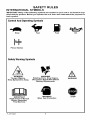
INTERNATIONAL SYMBOLS
RULES
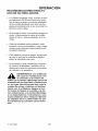
IMPORTANT: Many of the following symbols are located on your unit or on literature supplied with the product. Before you operate the unit, learn and understand the purpose for
each symbol.
Control And Operating Symbols
Slow
Fast
Fuel
Oil
Primer Button
Safety Warning Symbols
A
WARNING
WARNING
Thrown Objects.
Keep Bystanders Away,
Rotating Parts. Stop Engine.
Disconnect Spark Wire Before
Making Adjustments,
IMPORTANT
Read Owner's Manual
Before Operating
This Machine.
F_OO1102M
Wear
WARNING
Eye Protection
5
WARNING
STOP
ASSEMBLY
ASSEMBLY
Parts Packed Separately In Carton
1 - Owner's Manual (not shown)
1 - Container Of Oil
1 - Hair Pin
1 -HairPin
- Container
REMOVE
glasses
or eye
shields
while
asWARNING:
Always
wear
safety
sembling the Edger.
of Oil
THE
EDGER
FROM
THE
CARTON
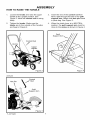
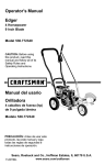
Figure 1 shows the Edger completely assembled.
References to the right or left side of the
Edger are from the viewpoint of the operatot's position behind the unit.
1.
Remove the bottle of oil and parts bag
from the carton.
2.
Cut down all four corners of the carton.
3.
Remove the packing material positioned
around the unit.
4.
Roll the Edger out of the carton and
place on a hard level surface.
Figure 1
F_001102M
6
ASSEMBLY
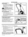
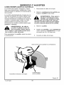
HOW TO RAISE THE HANDLE
1.
2.
Loosen the knobs and raise the upper
handle to the upright position. See
Figure 2. Allow the control rod to swing
freely.
3.
Tighten the knobs. Make sure the
knobs are to the outside of the handles
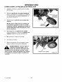
4.
Insert the end of the control rod from
left to right through the hole in the quill
support arm. Attach with hair pin found
in parts bag. See Figure 3.
When the clutch lever is in NEUTRAL
position, the quill support arm must be
close to the screw as shown in Figure 4.
as shown in Figure 2.
Quill
Support Arm
Control Rod
Upper
Handle
Figure 2
Figure 4
VZWVZW
Control
Hair
Pin
Rod
Quill
Support Arm
Figure 3
F_001102M
7
ASSEMBLY
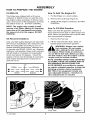
HOW TO PREPARE THE ENGINE
Fill With Oil
How
This Edger was shipped with a 20 ounce
container of SAE30 motor oil. Add this oil to
the engine before operating. To fill the crankcase, remove the oil fill cap/dipstick and add
the SAE30 motor oil DO NOT OVERFILL.
1. Put the Edger on a level surface.
2.
To Add The Engine
Remove the oil fill cap (Figure 5).
3. Slowly fill the engine crankcase.
OVERFILL.
NOTE: The engine may contain a small
amount of oil. When adding oil, frequently
insert the oil fill cap/dipstick and check
the amount of oil in the engine. DO NOT
OVERFILl.
Make sure that the gasoline container is
dean and free from dust or other foreign material. Never use gasoline that could be stale
from Iong periods of storage.
1. Remove the fuel cap.
Only use high quality detergent oil rated with
API service classification SG. SeIect the oil's
SAE viscosity grade according to your expected operating temperature. Although multi-viscosity oiIs (5w3g, lOW30, etc.) improve
starting in cold weather, these multi-viscosity
oils will result in increased oil consumption
when used above 32 degrees. Check the
engine oil level more frequently to avoid possible engine damage from running the engine low on oil.
2.
CoIder
5W30
_
--Warmer
SAE30
Fill the fuel tank with dean, fresh, unleaded grade automotive gasoline.
fuel container. Do not smoke
ARNING: Always use a safety
when adding the fuel mixture to
the engine. When inside an enclosure,
do not fill the fuel tank. Before you add
the fuel mixture, stop the engine. Let the
engine cool for several minutes.
NOTE: ENGINES WHICH ARE CERTIFIED
TO COMPLY WITH CALIFORNIA AND US
EPA EMISSION REGULATIONS FOR
ULGE ENGINES, are certified to operate
on regular unleaded gasoline. Include the
following
emission control system(s):
EM, TWC (if so equipped). Include any
user adjustable features - therefore no
other adjustments
are needed.
_l
;I
Fuel
Cap
Oil Fill
Cap
Fuel Tank
F-OOllO2M
DO NOT
How To Fill With Gasoline
Oil Recommendations
,4
4
Oil
8
Figure 5
ASSEMBLY
_" CHECKLIST
For the best performance and satisfaction
from this quality product, please review the
following checklist before you operate the
Edger:
II
All assembly instructions
completed.
have been
Check carton. Make sure no loose
parts remain in the carton.
All fasteners
ened.
have been properly tight-
As you learn how to use the Edger, pay extra
attention to the following important items:
_'P"
Engine oil is at proper level.
_'P"
Fuel tank is filled with a fresh, clean,
regular Unleaded gasoline.
_'P"
Become familiar and understand the
function of all controls. Before your
start the engine, operate all controls.
IMPORTANT: This unit is equipped with an internal combustion engine and must not be
used on or near any unimproved
forest-covered,
brush-covered
or grass-covered
land
unless the engine's exhaust system is equipped with a spark attester meeting
applicable local or state laws (if any). If a spark arrester is used, it must be maintained in
effective working order by the operator.
In the State of California the above is required by law (Section 4442 of the California
Public Resources Code). Other states may have similar laws. Federal laws apply on federal lands. A spark arrestedmuffler
is available through your nearest Sears Service Center (see the REPAIR PARTS section in this manual).
F-001102M
9
OPERATION
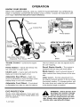
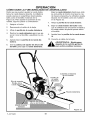
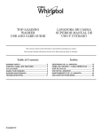
KNOW YOUR EDGER
READ THE OWNER'S
MANUAL AND ALL SAFETY RULES BEFORE YOU OPERATE the
Edger. To familiarize yourself with the location of the controls, compare the illustrations with
your Edger. Save this manual for future reference.
ENGINE
Clutch Lever
Control Rod
Primer Button
Throttle
Blade Guard
Control
VIEW OF BLADE AREA
Index Lever
Adjustable Rear Wheel
Adjustable Front Wheel
Throttle
Control
Blade
- Controls the engine
Figure 6
The front wheel can also be adjusted down
speed.
for curb-hopping.
Primer Button - Injects fuel directly into
the carburetor for faster starts.
equipped with an easy pull recoil starter.
Clutch
Lever
Recoil
Blade
- Use to start and stop the
Adjustable
Rear Wheel - Right rear
wheel is adjustable to level the Edger when
Wheel
is adjustable from side-to-side
i The engine is
- Use to prevent stones or
Index LeverPermits adjustment from
the edging (vertical) position to the trimming
edging along a curb (curb-hopping).
Front
Guard
Handle
other material from being thrown at the operator.
blade and control the depth of cut.
Adjustable
Starter
(horizontal) position. To change position, pull
the index lever and rotate the quill assembly
- Front wheel
for balance.
to the desired angle or position.
EYE PROTECTION
the Edger can result in foreign
WARNING: Debris thrown from
objects being thrown into the
eyes, which can cause severe eye damage. Always wear safety glasses or eye
shields when operating the Edger.
Always wear safety glasses. If you wear eye
glasses, put a Wide Vision Safety Mask over
your eye glasses.
F_OO1102M
10
OPERATION
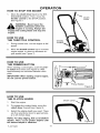
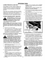
HOW TO STOP THE EDGER
1.
Move the clutch lever back to the DISENGAGED position. Then, move the
throttle control to the STOP position.
See Figure 7.
Clutch
Lever
EDGER unattended while the
WARNING: Never leave the
engine is running. Always disengage the cutting blade and stop the
engine.
_1
HOW TO USE
THE THROTTLE CONTROL
1.
During normal use, run the engine at full
speed.
2.
Move the throttle control up to increase
engine speed, or down to decrease engine speed (see Figure 7).
Throttle
ControI
HOW TO USE
THE PRIMER BUTTON
When starting a cold engine, push the primer button five times (see Figure 8). Wait
approximately two seconds between each
push.
IMPORTANT: When starting a warm engine,
do not use the primer button.
_'_Pri_mer
J
Button
Figure 8
HOW TO USE
THE CLUTCH LEVER
Clutch Lever
1.
Start the engine.
2.
To engage the cutting blade, move the
clutch lever forward (see Figure g).
3.
Select the edging depth you need. There
are five selections down to approximately 2-3/4 inches deep.
NOTE: For deep edging, first cut at shallow
depths. Then, cut at greater depths until
the desired depth is obtained.
F_OO1102M
Figure 9
11
OPERATION
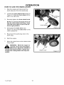
HOW TO USE THE INDEX LEVER
1.
Stop the engine and disconnect the
spark plug wire from the spark plug.
2.
Loosen the front wheel knob shown in
Figure 10. Slide the front wheel all the
way to the right side.
3.
F_ntWheel
Knob
Securely tighten the front wheel knob.
NOTE: To prevent the blade from hitting the wheel while trimming, make
sure the front wheel is set in the extreme right position.
4.
Disengage the index lever (see
Figure 11). Move the index lever to the
notch marked 90°.
5.
Reconnect the spark plug wire to the
spark plug.
6.
Start the engine.
7.
Move the clutch lever to the desired trim-
Front Whee_
Figure 10
ming height.
running, never leave the Edger.
WARNING: While the engine is
Before you adjust the wheels or
change the blade position, always disengage the cutting blade and stop the
engine.
,_
F-OOllO2M
Index Lever
Figure 11
12
OPERATION
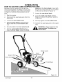
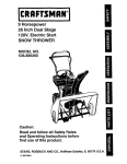
HOW TO USE THE CURB-HOPPING
FEATURE
wheel until the front wheel is level with
Because the front wheel and the right rear
wheel are adjustable, the Edger can be used
on uneven surfaces, such as the curb shown
in Figure 12. Set the wheel positions as foliows.
the left rear wheel and the unit is setting
on the curb as shown in Figure 12.
7.
Loosen the rear wheel knob.
8.
Lower the right rear wheel until the
Edger is level and the left rear wheel is
on the curb.
9.
Securely tighten the rear wheel knob.
1.
Stop the engine.
2.
Disconnect the spark plug wire from the
spark plug.
3.
Loosen the front wheel knob.
4.
Slide the front wheel to the best position to clear the curb and balance the
unit.
10. Connect the spark plug wire to the spark
plug.
5.
Securely tighten the front wheel knob.
1_
6.
Use the curb height adjust lever to
lower the front wheel. Lower the front
WARNING:
Keep away from the
rotating blade. The blade can
cause injury.
Blade Guard
Front
Wheel Knob
Support Rod
Rear Wheel Knob
Front Wheel
Adjust Lever
Rear Wheel
Figure 12
F-001102M
13
OPERATION
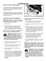
HOW TO STOP THE ENGINE
To stop the engine, move the clutch lever all
the way back to the DISENGAGED position.
Then, push the throttle control lever down to
the STOP position.
If the engine will not stop, hold a screwddver
against the spark plug and against the engine
cooling fins. The spark will go to ground and
the engine will stop.
Primer Button
" Figure 13
HOW TO START THE ENGINE
NOTE: Do not use the primer button to start
a warm engine.
IMPORTANT: Before you start the engine,
operate the controls several times. Make
sure all controls move freely.
7. To start engine, hold the recoil starter
handle firmly with your right hand.
1. Check the oil.
8.
2. Fill the fuel tank with regular unleaded
gasoline. Make sure the gasoline is
clean. Leaded gasoline will increase deposits and shorten the life of the valves.
Hold the edger handle firmly with your left
hand.
9. Quickly pull the recoil starter handle. DO
NOT allow the starter rope to snap back.
Let the starter rope slowly rewind. If engine fails to start after three pulls, push
primer button two times and again pull
the recoil starter handle.
NOTE: Do not use gasohol or methanol. Do
not use premium unleaded gasoline.
10.When the engine starts, move the throttle
controI lever up (FAST position) to increase speed or down to decrease
speed. During normal use keep the
throttle in the FAST position.
gasoline container. Do not
ARNING: Always use a safety
smoke when adding gasoline to
the fuel tank. When inside an enclosure,
do not add gasoline. Before you add
gasoline, stop the engine and let the engine cool for several minutes.
_lb
11. If the engine does not start in 5 or 6 tries,
See the "Problem and Repair" Instructions.
3. Make sure the spark plug wire is connected to the spark plug.
NOTE: The cutting blade speed is controlled by the engine speed. To reduce the
cutting blade speed, push down on the
throttle control lever. To increase the cutting blade speed, pull up on the throttle
4. Pull the clutch lever all the way back to
raise and disengage the blade.
control
5. Move the throttle controI lever to the
_ever.
FAST position.
,_
6. Some models have a primer button on
the front or side of the engine (Figure 13).
Every time you push the primer button,
wait two seconds. For the number of
times required to push the primer button, see the engine manufacturer's instructions.
F=001102M
14
indoors or in a poorly ventilated
WARNING: Never run the engine
area. Engine exhaust contains
carbon monoxide, an odorless and
deadly gas. Keep hands, feet, hair and
loose clothing away from any moving
parts. Avoid the muffler and surrounding areas. Temperatures can exceed 150
degrees.
OPERATION
EDGING TIPS
•
Edging is best performed when conditions
are dry. If the soil is to wet, dirt becomes
packed around the blade causing premature belt wear and decreased performance.
•
If dirt does become packed around the
blade, stop the engine and remove the
wire from the spark plug. Remove the
packed dirt and debris from the blade.
•
For deep edging, first cut at shallow
depths. Then, cut at greater depths until
the desired depth is obtained.
•
For uniform edging, make sure the blade
guide rides on the surface.
•
Edging can be customized by varying the
number of passes and by the distance the
blade is from the surface.
manual. Know location and
WARNING: Read the Owner's
functions of all controls. Keep
all safety devices and shields in place.
Never allow children or uninstructed
adults
before
pairs.
chine.
tating
to operate Edger. Shut off engine
unclogging blade or making reKeep bystanders away from ma=
Keep away from the blade all roparts, which cause injury.
F_001102M
15
MAINTENANCE
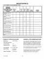
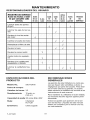
CUSTOMER RESPONSIBILITIES
SERVICE
RECORDS
Fill in dates as you
complete regular
service.
Before
Each
Use
Often
Every Every Before
10
25
Each Before
Hours Hours Season Storage
=
Lubdcate
Points
All Pivot
I
I
I
I
I
I
I
I
.
.
SERVICE
DATES
I
Lubricate Wheel
Axles
I
Check Engine Oil
Level
.......
N/
.....
Change Engine Oil
I
Replace Air Cleaner
Filter
Check Spark Plug
I
Check Drive Belt
I
,
.,f
I
.
I
.
Tighten All Fasteners
Check Blade For
Wear Or Damage
,
I
N
Lubricate Quill Rod/
tube
PRODUCT SPECIFICATIONS
Model No.:
GENERAL RECOMMENDATIONS
536.772400
The warranty on this Edger does not cover
items that have been subjected to operator
abuse or negligence. To receive full value
from the warranty, the operator must maintain the Edger as instructed in this manual.
Date Of Purchase:
Horse Power:
3.5
Displacement:
10 cu. in.
(163 co.)
Oil Capacity:
Spark Plug:
Spark Plug Gap:
F-001102M
Some adjustments must be made periodically to properly maintain your Edger.
20 oz. SAE-30W
Champion
RJ17LM
All adjustments in the Service and Adjustments section of this manual must be
checked at least once each season.
0.030 inch
16
MAINTENANCE
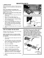
LUBRICATION
After each 25 hours, apply a small amount of
engine oil to all moving parts, particularly the
wheels.
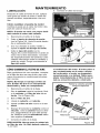
How To Change The Engine Oil
Change the oil in the engine crankcase
each 25 hours of use.
after
NOTE: The oil will drain more freely when
the engine is warm.
1.
Disconnect the spark plug wire from the
spark plug.
2.
Remove the oil drain plug (see
Figure 14). Drain the oil into a flat pan.
3.
After draining all the oil, install and tighten the oil drain plug.
4.
Remove the oil fill cap (see Figure 15).
Fill the engine crankcase. Pour slowly.
Do not overfill. See "Product Specifications" for amount and type of oil. install
the oil fill cap.
5.
Oil Drain Plug
Figure 14
Oil Fill Cap
i
Connect the spark plug wire to the spark
plug.
Figure 15
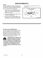
HOWTO CHANGETHE AIR FILTER
CAUTION: Never run the engine without
the air filter. A defective air filter will
Replace the air filter once a year; more often
in dusty or dirty conditions.
cause a loss of engine power. If dirt or
dust enters the engine through the carburetor, the result will be excessive wear or
damage to the engine. Replace a damaged or clogged air cleaner immediately.
NOTE: DO NOT clean or oil the air filter.
The air filter is not serviceable and must
be replaced.
1.
Disconnect the spark plug wire from the
spark plug.
2.
Turn the cover to the left (counterclockwise). Remove the cover and the air filter from the flange. (see Figure 16).
3.
Discard the air filter.
4.
Clean the cover and the flange.
5.
Install a new air filter into the cover.
6.
Push the cover firmly against the
flange. Turn the cover to the right
(clockwise) until tight. Make sure the retainers are locked around the flange.
Connect the spark plug wire to the spark
plug.
F_001102M
To Remove,
Turn Counterclockwise
,
Flange
AirFilt_etain(_
(
To Install,
Turn Clockwise
7.
Figure 16
17
MAINTENANCE
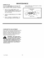
SPARK
PLUG
Check the spark plug every 25 hours. Replace the spark plug if the electrodes are
pitted, burned, or if the porcelain is cracked.
1.
Make sure the spark plug is clean.
Clean the spark plug by carefully scraping the electrodes (do not sand blast or
use a wire brush).
2.
Check the spark plug gap with a feeler
gauge.
3.
Before installing the spark plug, coat
the threads lightly with oil for easy re-
moval. Tighten the spark plug to a torque
of 15 foot-pounds.
Feeler Gauge
0.030"
Spark Plug
CARBURETOR
Figure I
ADJUSTMENT
Never make unnecessary adjustments to the
carburetor. The carburetor was set at the
factory to operate efficiently under most applications. However, if adjustments are required, we recommend you contact your
nearest Sears Service Center.
nor
is set atThe
the engine
factory. goverDo not
WARNING:
change the governor setting.
Over speeding the engine above the factory setting can be dangerous. If you
think the engine governor needs an adjustment, contact your nearest Sears
Service Center.
F-001102M
18
SERVICE AND ADJUSTMENT
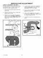
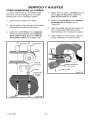
HOW TO REMOVE THE BELT
The belt made of a special compound, if the
belt becomes worn or breaks, replace the
belt with an original equipment belt.
4.
Loosen, do not remove, the screw that
holds the belt guide. Then, move the
belt guide away from the belt.
Remove the two screws from the belt
1.
Disconnect the spark plug wire from the
spark plug.
5.
2.
Pull the clutch lever back to release the
tension from the belt.
6.
Remove the two screws and spacers
from the top of the engine pulley cover.
Remove the engine pulley cover (see
Figure 18).
Remove the oid belt from the engine
and quill assembly pulleys. Replace with
an original equipment belt.
7.
To install a new belt, reverse the above
3.
guard (see Figure 19).
steps.
@
Belt Guard
_.._
Screw
Figure 19
Screws
F-001102M
Figure 18
19
SERVICE AND ADJUSTMENT
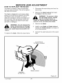
HOW TO REPLACE THE BLADE
The blade is subject to wear and damage,
such as nicks and dents. This will not generally affect its function.
The blade is designed to not require sharpening. Do not attempt to sharpen the blade.
The blade is also reversible. If nicks or
dents are excessive, remove the blade and
turn it around. This will provide a fresh cutting edge. Replace the blade if both sides
are worn or damaged.
1.
Disconnect the spark plug wire from the
spark plug.
2.
Remove the blade Iocknut that holds
the blade to the drive shaft.
ten the blade Iocknut, always
WARNING: To remove or tighuse the method shown in
,_
Figure 20. Always position the holding
wrench on the nut behind the blade.
3.
blade. Sharpening can damage
WARNING: Do not sharpen the
the blade and cause it to break,
4.
Remove the blade.
Install a new blade and blade Iocknut.
Tighten the blade Iocknut
40-45 foot pounds.
which can cause injury to yourself or to
others.
5.
To replace the blade, follow the steps below.
to a torque of
Connect the spark plug wire to the spark
plug.
Turn Wrench
To Tighten Locknut
Blade Locknut
Hold Nut,
Do Not Turn
Figure 20
F_OO1102M
20
SERVICE AND ADJUSTMENT
STORAGE
Edger indoors with fuel in the
WARNING: Never store the
fuel tank. Never store in an enclosed, poorly ventilated area where
fumes could reach an open flame, a
spark or a pilot light as on a furnace, water heater or clothes dryer.
parts such as the carburetor, fuel filter,
fuel hose, and tank during storage. Also,
using alcohol-blended
fuels (called gasohol, ethanol or methanol) can attract
moisture which leads to separation and
formation
of acids during storage. Acidic
gas can damage the fuel system of an engine while in storage.
oline while inside a building,
ARNING: Do not remove gasnear a fire, or while you smoke.
Gasoline fumes can cause an explosion
To prevent engine damage when the Edger
is in storage for 30 days or more, follow the
steps below:
_1_
_lb
or
a fire.
Let the engine run until it is out of gasoline.
When the Edger is put in storage for thirty
days or more, follow the steps below to
make sure the Edger is in good condition the
following season.
If you do not want to remove the gasoline, add a fuel stabilizer to any gasoline
Ieft in the fuel tank. A fuel stabilizer will
minimize gum deposits and acids. If the
fuel tank is almost empty, mix the fuel
stabilizer with fresh gasoline in a separate container and add the mixture to the
Edger
Completely dean the Edger.
Check the Edger for worn or damaged
pads. Tighten all loose hardware.
fuel tank. Always follow the instructions
on the stabilizer container. Start the engine. Let the engine run for 10 minutes
to allow the mixture to reach the carburetor.
Apply a smatI amount of engine oil to all
moving parts, particularly the wheels.
Put the Edger in a building that has good
ventilation.
Change the engine oil. See "How To
Change The Engine Oil" in the Maintenance section.
Cover the Edger with a suitable protective cover that does not retain moisture.
Do not use plastic.
Lubricate the piston/cylinder area. This
can be done by first removing the spark
plug and squirting a small amount of
clean engine oil into the spark plug hole.
Then, cover the spark plug hole with a
rag to absorb oil spray. Next, rotate the
engine by pulling the starter two or three
times. Finally, install the spark plug and
attach the spark plug wire.
IMPORTANT: Never cover the Edger while
the engine and exhaust areas are still
warm.
NOTE: A yearly checkup or tune-up by a
Sears Service Center is a good way to
make sure that your Edger will provide
maximum performance
for the next season.
Store the Edger in the operating position
with the wheels down. If the Edger is
stored in any other position, oil from the
crankcase will enter the cylinder and
cause a service problem.
Engine
IMPORTANT: It is important to prevent
gum deposits from forming in fuel system
F-001102M
21
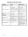
TROUBLE
SHOOTING
CHART
TROUBLE
CAUSE
CORRECTION
Engine difficult to start
Stale fuel
Drain fuel tank. Fill with fresh
fuel.
Clogged fuel filter
Replace fuel filter
Dirt in fuel tank or out of fuel
Clean fuel tank.
Carburetor out of adjustment
Take unit to a Sears Service
Center.
Fouled spark plug
Clean and set spark plug
gap.
Dirty air filter
Replace air filter.
Plugged air filter
Replace air filter.
Debris interfering with blade
Clean debds from blade.
Loose blade
Tighten blade nut.
Defective V-beIt
Replace V-belt.
Defective quiil bearings
Replace the quill assembly.
Damage or worn btade
Reverse the blade or replace
the blade.
Loose parts
Stop engine immediateiy.
Tighten all fasteners. If
vibration continues, take the
unit to a Sears Service
Center.
or
Engine runs erratically
or
Engine will not run at full
speed
Engine smokes
excessively
Cutting blade will not
rotate
Blade will not cut properly
Excessive
F-001102M
vibration
22
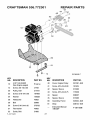
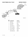
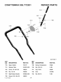
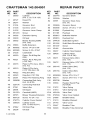
CRAFTSMAN
536.772301
REPAIR PARTS
43
44
4O
45
22
29
81
12
KEY
NO. DESCRIPTION
4HP 143.604001
(See Enginepages)
Engine
12
Screw,3/8-16xl .O0
47792
20
Pulley,Half
314781
22
Screw,5/16-24x1.06
181608
24
Washer
120638
26
Flatwasher
45602
29
Belt
32668
30
Screw5/16-24x1.60
578733
31
Flatwasher
45602
32
Guide,Belt
51600
F=OO1102M
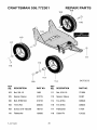
KEY
NO. DESCRIPTION
PARTNO.
10
323095
23
F
PARTNO.
40
Cover,Engine Pulley
331281-848
41
Screw,5/16-24x3.60
181624
42
Spacer,Sleeve
315095
43
Screw,5/16-24x3.75
173036
44
Spacer
308237
45
Spacer,Sleeve
315095
80
Assembly,Frame
323534-848
81
Strap
308154-848
__
InstructionManual
ENG/SP
F-OOllO2M
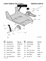
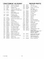
CRAFTSMAN
536.772301
REPAIR PARTS
1
2
4
5
332247 E
KEY
NO. DESCRIPTION
F=OOllO2M
PARTNO.
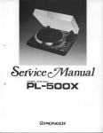
1
BladeGuard
331076-848
2
Bolt,Carriage
57072
4
Nut,5/16-18
710205
5
Guide,BeltFront
326748-848
6
Screw,1/4-20x.50
710264
8
Cover,QuillPulley
53405-848
9
Screw,10-16x.50
710271
Decal,BladeGuard
333874
24
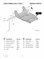
CRAFTSMAN
536.772301
REPAIR PARTS
_163
151
J
150
164
160
157_
155
154
158
331765 E
159
KEY
NO. DESCRIPTION
PARTNO.
KEY
NO. DESCRIPTION
PARTNO.
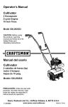
150
FrontWheelArm
339299-848
157
Knob,Rectangle
20252
151
FrontCurbHopper
740132
158
Flatwasher
22265
152
Pushnut,Washer
338614
159
Nut
45905
153
PlasticWasher
325892
160
Screw,5/16-18x.63
51333
154
Spacer,HeightAdjust
331421
161
Plate,HeightAdjust
331394-848
155
Pin, Spring
332002
163
Knob, Molded
339388
156
Lever,HeightAdjust
331419
164
Nut, 5/16-18
710205
F=OOllO2M
25
CRAFTSMAN
536.772301
REPAIR PARTS
184
182
183
170
172
186
323179 F
KEY
NO. DESCRIPTION
PARTNO.
KEY
NO. DESCRIPTION
PARTNO.
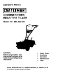
170
Bracket,CurbHop Mnt
6842
182
Spacer,Sleeve
45222
171
Screw,5/16-18x.75
180077
183
Flatwasher
120393
172
Nut,5/16-18
1498
184
Knob,Wing5/16-18
671294
180
Bolt,5/16-18x2.00
126380
186
Rod,WheelSupport
310896
181
Clevis
8082
F_OO1102M
26
CRAFTSMAN
536.772301
REPAIR PARTS
330
331
329
323
321
301
325
311
305
323129 E
KEY
NO. DESCRIPTION
PARTNO.
KEY
NO. DESCRIPTION
PARTNO.
300
Flatwasher
120396
321
Quill Assembly
338070
301
Quill Support
338656-848
322
Lever,Index
308466
302
Bolt,3/8-16
308254
323
Spring,Torsion
308155
303
Flatwasher
710083
325
Nut, 5/16-18
1498
305
Nut,3/8-16
1499
329
Flatwasher
22265
310
RubberDeflector
308243
330
Blade,Edger
740296
311
Screw,10-16x1.56
710271
331
Nut, 1/2-28
46023
320
Spring
51603
F_OO1102M
27
CRAFTSMAN
536.772301
REPAIR PARTS
751
\
\
X
\
425
\
\
\
\
\
720
\
\
\
\
\
\
\
721
754
722
343718 A
KEY
NO. DESCRIPTION
PARTNO.
KEY
NO. DESCRIPTION
PARTNO.
424
Bolt,5/16-18xl.75
315288
722
Screw,5/16-18x.63
51333
425
Knob,Wing5/16-18
671294
750
Control Rod
580292-853
720
LowerHandle
740127-853
751
HairPin
36368
721
Nut,5/16-18
1498
754
HairPin
36368
F=OO1102M
28
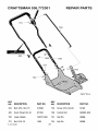
CRAFTSMAN
536.772301
REPAIR PARTS
737
743
745
731
739
725
738
732
735
323136 F
KEY
NO. DESCRIPTION
PARTNO.
KEY
NO. DESCRIPTION
PARTNO.
725
UpperHandle
740147
739
Spring,Compression
25644
731
SelectorPlate
310052-853
740
Nut,5/16-18
1498
732
Screw,1/4-20x1.25
180024
741
Grip,Hand
56924
Stud
310053
Nut,3/8-16
1499
735
Nut,1/4-20
782585
743
737
DepthAdjustHandle
310050-853
745
738
Screw,5/16-18x1.25
180081
F=OOllO2M
29
CRAFTSMAN
536.772301
REPAIR PARTS
105
108
106
116
117
110
118
113
114
109
343720 B
KEY
NO. DESCRIPTION
PARTNO.
KEY
NO. DESCRIPTION
PARTNO.
103
Nut,3/8-16
1499
111
710205
105
Spacer,Sleeve
310715
113 Spacer,Sleeve
51887
106
Bolt, HHSH3/8
310716
114 Tire& Rim
336546
108
Tire&Rim
336545
116 Tire& Rim
336545
109
Screw,5/16-18x3.08
180113
117
17X91
110
Flatwasher
120393
118 CotterPin
F_OO1102M
30
Nut,5/16-18
Flatwasher
121222
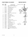
CRAFTSMAN
KEY
N0,
143.004001
PART
NO.
REPAIR PARTS
Carburetor No. 640172
DESCRIPTION
0
640172
Carburetor (Incl. 184 of Engine Parts
1
631615
Throttle Shaft & Lever Assembly
2
4
631767
631184
Throttle Return Spring
Dust Seal Washer
5
631183
Dust Seal (Throttle)
F,
".4
7
6
,0...
lz....._f
7
650506
Shutter Screw
16
632164
Fuel Fitting
_/"
17
651025
Throttle Crack Screw/Idle
,_,
Speed
I y
J
_20
Screw
\20A
i
48
(("
!
!'_']
29/
18
630766
Tension Spring
20A
20
25
640053
640018
631867
Idle Restrictor Screw Cap
Idle Restrictor
Screw
Float
Bowl
27
631024
Float Shaft
_--37
28
632019
Float
_--36
29
631028
Float Bowl "O" Ring
30
631021
Inlet Needle, Seat, & Clip (Incl. 31)
31
631022
Spring Clip
35
36045A
Primer Bulb/Retainer
36
640019
Main NozzIe Tube
7
28/" _'31"_'_" j
Ring
25/
37
632547
"O" Ring, Main Nozzle Tube
40
640074
High Speed Bowl Nut
44
27110A
Bowl Nut Washer
47
630748
Welch Plug, Idle Mixture Well
48
631027
Welch Plug, Atmospheric
60
632760
Repair kit (Incl. Items Marked PK in
Notes)
F-001102M
_--37
_,_"_//_
44/(_
40
31
Vent
/2
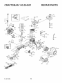
CRAFTSMAN
143.004001
REPAIR PARTS
169
287
370K
F-OO1102M
32
CRAFTSMAN
KEY
NO,
PART
NO.
1
36560
2
143.004001
REPAIR PARTS
KEY
NO,
PART
NO,
Cylinder"
80
30574A
Governor Shaft
(Incl. 2, 20, 72 & 128)
Dowel Pin
81
30590A
Washer
26727
82
30591
14
28277
Washer
Governor Gear Ass'y.
(Incl. 81)
15
31334
Govemor
Rod
83
30588A
Governor Spool
16
31336
Govemor
Lever
86
650488
Screw, I/4-20
17
31335
Governor Lever Clamp
89
610961
Flywheel Key
18
651018
Screw
90
611195
Flywheel
19
34593
Extension
92
650815
Belleville Washer
20
32600
Oil Seal
93
650816
Flywheel Nut
28
36552
100
102
34443A
651024
Solid State Ignition
25A
35883
Blower Housing Baffle
(Incl. 262)
Baffle Extension
103
651007
Screw
26
650802
Screw, 1/4-20 x 5/8"
110
35182
Ground Wire
26A
30
650926
37336
Screw, 8,-32 x 21/64"
Crankshaft
119
36437
Cylinder Head Gasket
120
36438
40
40020
Piston, Pin & Ring Set
Cylinder Head
(Incl. 119 & 130)
(Std.)
125
36471
40
40021
Piston, Pin & Ring Set
(.010" OS)
Exhaust Valve (Std.)
(Incl. 151)
125
36472
41
40018
Piston & Pin Ass'y. (Std.)
Exhaust Valve (1/32" QS)
(Incl. 151)
126
29314C
41
40019
Piston & Pin Ass'y.
Intake Valve (Std.)
(Incl. 151)
29315C
40022
(.010" QS) (Incl. 43)
Ring Set (Std.)
126
42
Intake Valve (Std.)
(Incl. 151)
42
40023
Ring Set (.010" QS)
130
656694A
Screw, 5/16-18
x 2"
43
20381
Piston Pin Retaining Ring
130A
6021A
Screw, 5/16-18
x 1-1/2"
48
30963B
Connecting
132
650708
Washer
135
33636
46
32610A
Connecting
Resistor Spark Plug
(RJ17LM)
48
27241
Valve Lifter
156
31672
Valve Spring
49
28594
Oil Dipper
151
31673
Valve Spring Cap
50
32197A
Camshaft
151A
40016A
Valve Seal
60
29745
Blower Housing Extension
169
27234A
Valve Cover Gasket
65
650128
Screw, 10-24 x 1/2"
170
27666
Breather Body
69
27677A
Cylinder Cover Gasket
171
31410
Breather Element
70
35863A
Cylinder Cover
(Incl. 75 thru 83,311)
172
173
34146
32447
Valve Cover
72
75
27642
26208
Oil Drain Plug
Oil SeaI
173A
32446
Breather Tube Grommet
DESCRIPTION
Spring
(Incl. 43)
Rod Ass'y.
(Incl. 46 & 49)
F-OO1102M
Rod Bolt
(MCR)
33
DESCRIPTION
x 1-1/4"
SoW State Mounting Stud
Breather Tube
CRAFTSMAN
143.004001
REPAIR PARTS
Fuel Line
174
650783
Screw, 10-24 x 3/4"
290
29774
178
29752
Nut & Lock Washer
292
26460
Fuel Line Clamp
179
30593
Retainer Clip
298
650665
Screw, 1/4-15 x 3/4"
182
6201
300
35591
184
26756
Carburetor To Intake Pipe
Gasket
Fuel Tank
(incl. 292 & 301)
301
36246
Fuel Cap (Black)
185
36703
305
307
35554
35499
Oil Fill Tube
186
31341
Intake Pipe
(Incl. 182,184, 224)
Governor Link
308
35539
Fill Tube Clip
200
36677
310
35556
Dipstick
313
34080
Spacer
339
28212
Spacer
346
35926
Fuel Tank Bracket
342
650751
Screw, I/4-20
345
32664
Baffle Heat
376A
36261
Lubrication Decal
376B
35703
Throttle Decai
376C
37199
Primer Decal
376K
36695
Starter Decal
386
640172
Carburetor
396
590732
Recoil Starter
(NOTE: This engine could
have been built with
596738
starter).
406
36439
Gasket Set (Incl. Items
Marked PK in Notes)
416
36085
Spark Arrestor Kit
(Incl. 417) (Optional)
417
650821
Screw, (Optional)
Screw, 1/4-28 x 7/8"
Control Bracket
(Incl. 203 thru 209A)
203
31342
Compression
204
651029
Screw, T-10, 5-40 x 7/16"
266
610973
Terminal
215
32410
Control Knob
Spring
223
650451
Screw, 1/4-20 x 1"
224
26754A
Intake Pipe Gasket
238
650932
Screw, 10-32 x 49/64"
239
34338
Air Cleaner Gasket
241
35797
Air Cleaner Collar
245
35066
Air Cleaner (Conical)
250
35065
Air Cleaner Cover
260
35585
Blower Housing
262
650737
Screw, 1/4-20 x 1/2"
275
46066A
Muffler (W/Catalyst)
277
650988
Screw, 1/4-20 x 2-5/16"
285
36467A
Starter Cup
287
650926
Screw, 8-32 x 21/64"
F-001102M
34
"O" Ring
x 7/16"
(Incl. 184)
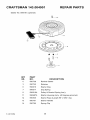
CRAFTSMAN
143.004001
REPAIR PARTS
Starter No. 590732
11
12
7
6
7
_
O
.__.._ 46
(_)
KEY
NO.
F-001102M
PART
NO.
3
DESCRIPTION
o
890732
Rewind Starter
1
590599A
Spring Pin (Incl. 4)
2
590600
Washer
3
590696
Retainer
4
590601
Washer
5
590697
Brake Spring
6
590698
Starter Dog
7
590699
Dog Spring
8
590700
Pulley & Rewind Spring Ass'y.
11
590695
Starter Housing Ass'y. (40 degree grommet)
12
590535
Starter Rope (Length 98" x 9/64" dia.)
13
590701
Starter Handle
35
CRAFTSMAN
Starter No. 590738
143.004001
REPAIR PARTS
(optional)
12
13
_
KEY
NO.
F-001102M
PART
NO.
7
DESCRIPTION
o
590738
Rewind Starter
3
590740
Retainer
6
590616
Starter Dog
7
590617
Dog Spring
8
590618A
Pulley & Rewind Spring Ass'y.
11
590687A
Starter Housing Ass'y. (40 degree grommet)
12
590535
Starter Rope (Length 98" x 9/64" dia.)
13
590701
Starter Handle
14
590760
Spring Clip
36
CONTENIDO
GARANTiA
SiMBOLOS INTERNACIONALES
MONTAJE
OPERACION
MANTENIMIENTO
SERVICIO Y AJUSTES
37
40
41
45
51
54
TABLA DE LOCALIZACION DE
AVERIAS
57
PIEZAS DE REPUESTO
21
PIEZAS DE REPUESTO (MOTOR) 25
PEDIDOS / SERVICIO
CONTRACUBIERTA
GARANTiA
GARANTiA LIMITADA DE DOS AI_IOS PARA LA ORILLADORA
CRAFTSMAN
Esta orilladora Craftsman esta garantizada pot dos aSos a partir de la fecha de compra, siemprey cuando, se le haya dado mantenimiento, lubricaci6n y afinado de acuerdo con las instrucciones de operaci6n y mantenimiento que aparecen en el manual del usuario, Craftsman
reparara, sin costo alguno, cualquier defecto en eI material y/o mano de obra de la unidad.
Siesta orilladora Craftsman se utiliza para prop6sitos comerciales o de arrendamiento, la garantia sera v_lida por s61o 90 dias a partir de la fecha de compra.
Esta garantia no cubre Io siguiente:
•
Piezas reemplazables
que se desgasten durante el uso normal, por ejemplo: bujias, etc.
•
Reparaciones necesarias debido al abuso o negligencia pot parte del operador de la unidad, incluyendo cigLieSales torcidos, y por no mantener la unidad de acuerdo con las instrucciones que aparecen en el manual del usuario.
EN LOS ESTADOS UNIDOS, EL SERVICIO BAJO GARANTiA PAPA LA ORILLADORA
CRAFTSMAN ESTA DISPONIBLE EN EL CENTRO / DEPARTAMENTO DE SERVICIO DE
SEARS MAS CERCANO. ESTA GARANTiA ES VALIDA SOLAMENTE SI EL PRODUCTO
SE USA EN LOS ESTADOS UNIDOS.
Esta garantia le brinda derechos legales especiflcos, ademas, usted puede tener otros derechos legales que varian segQn el estado donde resida.
Sears, Roebuck and Co., D817WA,
Hoffman Estates, IL 60179
Las emisiones generadas pot el motor, algunos de sus compuestos
y ciertos componentes del vehiculo contienen o emiten vapores
quimicos reconocidos en el Estado de California como carcinbgenos, y pueden causar malformaciones congenitas y otros problemas reproductivos.
Los bornes, conectores y accesorios relacionados con la bateria
contienen plomo y compuestos del plomo. Estos quimicos est_n
reconocidos pot el Estado de California como carcinbgenos, relacionados adem_s con malformaciones congenitas y otros problemas reproductivos. DEBE LAVARSE BIEN LAS MANOS DESPUI_S
DE TOCARLOS.
F_001102M
37
NORMAS
Pr&cticas
de seguridad
DE SEGURIDAD
pars
la operacibn
de la orilladora.
ADVERTENCiA: Busque este simbolo que le indicarb puntos importantes
de precaucibn para su seguridad. Este simbolo quiere decir: "lAtencibn!
iEst_ alerta! Su seguridad estb en peligro".
el arranque accidental de la mb_L
DVERTENCIA:
Para prevenir
quina durante el montaje, transporte, ajuste o reparacibn,
desconecte
siempre el cable de Ia bujia y colbquelo
alejado de _sta.
Pasos preliminares
•
Lea detenidamente el Manual del usuario.
Debe familiarizarse completamente con los
controles y el uso correcto de la orilladora.
Aprenda c6mo apagar, detener y desenganchar los controles de la orilladora, en
caso de que tenga que hacerIo rapidamente.
• Nunca guarde la orilladora Ilena de combustible ni el recipiente de combustible en
un recinto donde haya alguna llama expuesta.
Operacibn
• Nunca permita que niSos o adolescentes
manejen la orilladora. Mant6ngalos fuera
del area de recorte. Nunca permita que
usen la unidad los adultos no familiarizados con las instrucciones de operaci6n.
• NO opere la orilladora siesta tomando algun farmaco u otra medicina que le provoque somnolencia o que afecte su habiIidad
de operar esta unidad con seguridad.
• No use la orilladora si no esta fisica o men-
• Siempre que use Ia orilladora debera vestirse con ropa apropiada y usar zapatos
que le protejan y le den buena tracci6n.
•
Mantenga el area de operaci6n despejada
de personas, especialmente de niSos pequeSos y mascotas.
•
Examine el _rea en donde va a ser usada
Ia orilladora y desp6jela de cualquier objeto
que pudiera ser lanzado por Ia maquina.
Combustible
• Tenga mucho cuidado al manejar gasolina
y otros combustibles, estos son sumamente inflamables.
•
Use _nicamente
•
Revise el nivel de combustible cada vez
que use la orilladora. Asegurese de dejar
suficiente espacio, ya que el calor del motor y/o del sol puede causar la expansi6n
del combustible.
•
•
recipientes
aprobados.
Debe reabastecer o Ilenar el tanque de
combustible en un _rea abierta y con mucho cuidado. Nunca Ilene el tanque en un
espacio cerrado. Fije bien la tapa deI tanque de combustible y limpie cuaIquier derrame.
talmente capacitado
nera segura.
para hacerlo de ma-
• Siempre use gafas de seguridad o caretas
protectoras al operar, ajustar o reparar la
orilladora, esto protegera sus ojos de objetos que pudieran ser lanzados por la unidad.
• No ponga las manes o los pies cerca o debajo de piezas giratorias.
• Preste mucha atenci6n cuando maneje la
orilladora cerca de la calle, o cuando cruce
por calzadas, calles o caminos de grava.
Est6 alerta tanto al trafico como a problemas potenciales o imprevistos.
• Tenga cuidado para evitar caidas o resbaIones.
• Nunca opere la orilladora sin colocar en su
lugar los respectivos resguardos u otros
aditamentos diseSados para su protecci6n
y seguridad.
• Nunca opere la odIIadora a alta velocidad
en superficies resbalosas. Siempre que
retroceda mire hacia atras y hagalo con
cuidado.
• Nunca permita que haya personas cerca
de la onlladora.
• Mantenga alejados a niSos y mascotas durante la operaci6n de la maquina.
Nunca quite la tapa del tanque de combustible ni afiada combustible al tanque cuan• Siempre opere el equipo a la luz del dia o
do el motor est_ caliente o en marcha.
con buena iluminaci6n artificial.
38
F_001102M
NORMAS
•
DE SEGURIDAD
Nunca ponga en marcha un motor dentro
de un recinto o de un area cerrada. Los
laridad todos los sujetadores para mantenerlos debidamente apretados.
vapores del escape son peligrosos, ya que
contienen MONOXIDO DE CARBONO,
UN GAS INODORO Y MORTAL.
Reparacion
• Tome todas las precauciones necesarias
cuando deje la orilladora desatendida.
Apague el motor.
•
/ Ajustes
Si golpea un objeto extraSo con la unidad,
apague el motor. Desconecte el cable de la
bujia y mant&ngalo alejado de 6sta para
evitar un arranque accidental del motor.
Inspeccione la orilladora para ver si 6sta
sufri6 algt3n daSo. Si est& averiada, deber&
repararla antes de hacerla funcionar nuevamente.
No sobrecargue la capacidad de su odlladora al tratar de rebordear a una profundidad o a una velocidad excesiva.
Si la orilladora
Almacenamiento
• Cuando la orilladora va a set almacenada
por un periodo largo de tiempo, consulte
ias instrucciones del manual deI usuario
para obtener detalles importantes ai respecto.
•
•
indicar que existe alguna averia.
Apague el motor siempre que tenga que
dejar el equipo. Desconecte el cable de la
bujia antes de destapar la cuchilla y antes
de realizar cualquier reparaci6n, ajuste o
inspecci6n a la unidad.
Nunca almacene la orilladora con combustible en el tanque, dentro de un recinto
donde pudieran haber fuentes de ignici6n
tales como calentadores de agua, estufas
secadoras de ropa y otras fuentes parecidas. Permita que el motor se enfrie antes
de guardar la unidad en un recinto cerrado.
Antes de limpiar, reparar o inspeccionar la
unidad, apague el motor y asegt3rese de
que todas las partes en movimiento se hayah detenido.
Nunca haga ajustes o reparaciones mientras el motor est6 en marcha, a menos que
el fabricante Io indique especificamente.
Mantenga la orilladora en condiciones de
funcionamiento seguras. Revise con regu-
F-OO1102M
comienza a vibrar excesiva
o anormalmente, apague el motor. Revise
la unidad de inmediato para determinar la
causa. Generatmente la vibraci6n suele
39
NORMAS
SiMBOLOS
DE SEGURIDAD
INTERNACIONALES
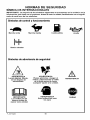
IMPORTANTE: La mayoria de los simbolos siguientes se encuentran en la unidad o en la
informacibn que viene con el producto. Antes de usar la unidad, familiaricese con el significado de cada uno de los simbolos.
Simbolos de control y funcionamiento
Marcha lenta
Marcha rapida
Combustible
Aceite
Botbn cebador
Simb010sde advertencia de seguridad
ADVERTENCIA
Lanza objetos. Mantenerse ale jado de
transeuntes,
IMPORTANTE
Lea el Manual del
usuario antes de
operar esta unidad,
F-OOllO2M
ADVERTENCIA
Piezas giratorias. Apagar el
motor y desconectar el cable
de la bujia antes de hacer
cualquier ajuste a la unidad.
ADVERTENCIA
Usar proteccibn para
los ojos
40
ADVERTENCIA
PARAR
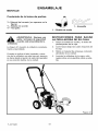
ENSAMBLAJE
MONTAJE
Contenido de la boisa de parties
1 -Manual del usuario (no aparece en la
figura)
1 - Botella de aceite
1 - Horquilla
1 - Horquilla
1 - Botella de aceite
INSTRUCCIONES
LA ORILLADORA
gafas / anteojos de seguridad
ADVERTENCIA:
Siempre use
cuando est_ ensamblando la
orilladora.
La Figura 21 muestra la orilladora
mente ensamblada.
completa-
Cuando se indica el lado izquierdo o derecho de la orilladora en este manual, siempre
se hace desde el punto de vista del operador
en su posici6n detr_s de la unidad.
PARA SACAR
DE SU CAJA
1.
Saque la botella de aceite y la bolsa de
piezas/partes de la caja.
2.
Corte hacia abajo ias cuatro esquinas de
Ia caja.
3.
Retire el material de empaque colocado
alrededor de la unidad.
4.
Levante la orilladora de la caja y col6quela sobre una superflcie plana y estable.
Figura 21
F-OOllO2M
41
ENSAMBLAJE
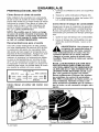
COMO LEVANTAR EL MANGO
1.
2.
3.
Afloje las perillas y levante el mango
superior a la posici6n vertical. Vet la
Figura 22. Deje que la vara de control
cuelgue libremente.
Apriete las perillas. Aseg[_re que las
perillas queden por el lado de afuera de
los mangos, como se muestra en la
Figura 22.
Inserte el extremo de la vara de control
de izquierda a derecha a trav6s del agujero en en brazo hueco de soporte. Sujete con la horquilla que viene en la
bolsa de partes. Ver la Figura 23.
4.
Cuando la palanca del embrague est_
en la posici6n NEUTRO, el brazo hueco
de soporte debe quedar junto al tornillo
como se muestra en Ia Figura 24.
Brazo hueco
Vara de
control
Mango
supenor
Figura 22
Figura 24
Vara de
Horquilla
control
Figura 23
F-OOllO2M
42
ENSAMBLAJE
PREPARACION DEL MOTOR
1. Coloque la orilladora sobre una superficie
plana
Cbmo Ilenar el cbrter de aceite
2. Saque la varilla indicadora
Esta orilladora fue enviada con una botella
de 20 onzas de aceite de motor SAE30. CoIoque este aceite en el motor antes de hacer
funcionar la unidad. Para Ilenar el carter de
aceite, quite la tapa / varilla indicadora de
aceite y aSada el aceite de motor SAE30.
NO LQ LLENE DEMASlADO.
3.
Cbmo
Recomendaciones
para el aceite
4
(32°F)
el tanque
de combustible
de que el recipiente de gasolina
y sin residuos o contaminantes.
gasolina vieja que haya sido alpor periodos de tiempo prolonga-
1. Quite la tapa del tanque de combustible.
2.
Use s61o aceite detergente de alta calidad
con una clasificaci6n de servicio API de SG.
La selecci6n del grado de viscosidad SAE
del aceite se hace seg_n la temperatura anticipada de funcionamiento. Aunque los aceites multiviscosidad (5W30, 10W30, etc.)
mejoran el arranque en temperaturas bajas,
su uso en temperaturas pot encima de los
32F (0°C) aumenta el consumo de aceite.
Compruebe el nivel de aceite con mayor fiecuencia para evitar un posible daSo al motor
por operar la unidad con poco aceite.
0C
Ilenar
Aseg[irese
est6 limpio
Nunca use
macenada
dos.
NOTA: Es posible que el motor ya tenga
un poco de aceite. Durante el proceso de
Ilenado del aceite, compruebe frecuente=
mente el nivel usando la varilla indicadora. NO LO LLENE DEMASIADO.
(Figura 25).
Llene lentamente el c&rter del motor. NO
LO LLENE DEMASlADQ.
Llene el tanque de combustible con gasolina de autom6vil limpia, nueva y sin
plomo.
recipiente de seguridad para el
DVERTENCIA: Use siempre un
combustible. No fume cuando
est_ reabasteciendo
el motor. No reabastezca dentro de un local cerrado.
Apague el motor antes de a_adir combustible. Deje enfriar el motor por varios
minutos.
_IL
NOTA: LOS MOTORES QUE HAN SIDO
CERTIFICADOS
PAPA CUMPLIR CON
LOS REGLAMENTOS
DE EMISIONES DE
LA EPA (EE.UU.) Y DEL ESTADO DE CALIFORNIA PAPA MOTORES ULGE, pue=
den usar gasolina regular sin plomo.
Estos reglamentos
incluyen los siguientes sistemas de control de emisiones:
EM, TWC (catalizador de triple accibn, si
esta instalado). Tambi_n incluye cualquiet accesorio ajustable por el usuario pot Io tanto, no es necesario ningt_n otto
ajuste.
I
M s,.o __I__M sca,ien e]
5w3o -
•I
C6mo Ilenar el c&rter del motor con
aceite
Tapa de
combustible
Tanque de combustible
F_001102M
43
Figura 25
ENSAMBLAJE
_" LISTA DE COMPROBACION
Para obtener un rendimiento 6ptimo y la mayor satisfacci6n de este producto de alta caIidad, favor de revisar la siguiente lista de
comprobaci6n antes de hacer funcionar su
orilladora:
Verifique que se han completado todas las instrucciones de montaje.
Revise la caja de envio para asegurar
que no quede en 6sta ninguna pieza
o parte.
Asegt_rese de que todos los sujetadores (pernos, tornillos, etc.) est6n bien
apretados.
A medida que vaya aprendiendo sobre el
uso de la ofilladora, preste especial atenci6n
a los siguientes puntos importantes:
_'_"
El nivel de aceite del motor es el correcto.
El tanque de combustible ha sido Ilenado con gasolina regular limpia, nueva y sin plomo.
Familiarfcese y entienda la funci6n de
todos los controles. Antes de hacer
arrancar el motor, verifique el funcionamiento de todos ios controles.
IMPORTANTE: Esta unidad est& equipada con un motor de combustibn interna y no
debe set usada en o cerca de ning_n terreno basto de cubierta forestal, de maleza o de
hierba a menos que el sistema de escape deI motor est_ equipado con un parachispas
que cumpla con las leyes locales o estatales aplicables (si existen). Si se usa el
parachispas, el operador debe mantenerlo en buenas condiciones.
Lo indicado anteriormente es requerido pot ley (Section 4442 of the California Public
Resources Code) en el estado de California.
Otros estados pueden tenet Ieyes similares. Las leyes Pederales aplican a los terrenos federales.
Para conseguir un parachispas/silenciador vaya a su Centro de Servicio Sears m&s cercano (consulte la seccibn de
PIEZAS DE REPUESTO en este manual).
F_001102M
44
OPERACION
CONOZCA SU ORILLADORA
ANTES DE HACER FUNCIONAR LA ORILLADORA, LEA EL MANUAL DEL USUARIO Y TODA LA INFORMACI6N
SOBRE SEGURIDAD. Para familiarizarse con la ubicaci6n de los controles, compare las siguientes
referencias futuras.
ilustraciones
con su orilladora. Guarde
este manual
para
MOTOR
Palanca de
embrague
Vara de
Bot6n cebador
Control del
acelerador
Cubierta protectora
de la cuchilla
VISTA DE LA CUCHILLA
Manija de
arranque
manual
CuchilIa
Rueda trasera ajustable
Rueda delantera ajustable /
Control del acelerador
Iocidad del motor.
Palanca de
reglaje
Figura 26
- ControIa la ve-
equilibrar la unidad. Tambi_n puede ajustarse hacia abajo para los bordillos.
Manija de arranque
manual
El motor
esta equipado con una manija de arranque
manual de facil uso.
Palanca de embrague
- Se usa para
hacer arrancar y parar la cuchilla y tambi_n,
para controlar la profundidad de corte.
Cubierta
protectora
de la cuchUla Protege al usuario contra objetos (piedras,
etc.) que pueden ser lanzados por la unidad.
Rueda trasera
ajustable
- La rueda
trasera derecha se puede ajustar para niveIar Ia orilladora cuando se usa para recortar
a Io largo de los bordillos.
Palanca de reglaje - Permite ajustar la
unidad de la posici6n de orilladora (vertical)
a la posici6n de recortadora (horizontal). Para cambiar la posici6n, jale la palanca y gire
el brazo hueco de apoyo ai angulo o posici6n deseada.
i
Boton cebadorInyecta el combustible
directamente al carburador para facilitar el
arranque.
Rueda delantera
ajustable
- La rueda
delantera se ajusta de un lado a otro para
PROTECCION PARA LOS OJOS
orilladora lance objetos hacia
ADVERTENCIA:
Puede que Ia
los ojos, Io cual puede resultar
en lesiones graves. Use siempre gafas
de seguridad o caretas protectoras durante Ia operacibn de la orilladora.
Use siempre galas o anteojos de seguridad.
Si ya usa anteojos, p6ngase una careta protectora encima de estos.
F_001102M
45
OPERACION
COMO DETENER LA
ORILLADORA
1.
_i
Mueva la palanca de embrague hacia
atras hasta la posici6n DESENGANCHADA. Luego> mueva el control del
acelerador a la posici6n de PARADA.
Vet la Figura 27.
embrague
ORILLADORA
desatendida
DVERTENCIA:
Nunca deje la
mientras el motor est_ en mar-
cha. Siempre desenganche
pare el motor.
la cuchilla y
COMO USAR EL CONTROL
DEL ACELERADOR
1.
Durante periodos de uso normal, opere
el motor a toda velocidad.
2.
Mueva el control del acelerador hacia
arriba para incrementar la velocidad del
motor, o hacia abajo para aminorarla
(vet la Figura 27).
Control
del aceleradoi
COMO USAR EL BOTC)N
EL BOTC)N CEBADOR
Cuando deba arrancar el motor en frio, oprima el botbn cebador cinco veces (ver la
Figura 28). Espere aproximadamente dos
segundos entre cada pulsaci6n.
IMPORTANTE: No use el botbn cebador para hacer arrancar un motor caliente.
Bot6n
cebador
Figura 28
COMO USAR LA PALANCA DEL EMBRAGUE
1.
Arranque
2.
Para enganchar la cuchilla, mueva la
palanca del embrague hacia adelante
(ver la Figura 29).
el motor.
3.
Seleccione la profundidad de corte que
desea. Puede seleccionar entre cinco
opciones, lamas baja siendo de aproximadamente 7 cm (2-3/4 pulgadas) de
profundidad.
Palanca de
embrague
NOTE: Para un bordeado mas profundo,
haga el primer corte a poca profundidad.
Luego haga cortes robs profundos
hasta
Iograr Ia profundidad
deseada.
F_001102M
Figura 29
46
OPERACION
COMO USAR LA PALANCA DE REGLAJE
1.
Apague el motor y desconecte
de la bujia.
2.
Afloje la perilla de la rueda delantera
que se muestra en la Figura 30. Deslice
completamente la rueda delantera hacia el lado derecho.
3.
el cable
Perilla de
la rueda
delantera
Apriete bien la perilla de la rueda deIantera.
NOT,&.: Para evitar que la cuchilla de
la orilladora golpee contra Ia rueda
mientras recorta, asegt_rese de que la
rueda delantera est_ ubicada en el extremo derecho.
4.
Desenganche la palanca de reglaje
(vet la Figura 31). Mueva la palanca de
reglaje hasta la ranura marcada 90 °.
5.
Reconecte el cable de la buiia.
6.
Arranque
7.
Mueva la palanca de embrague hasta
iograr la altura de recorte deseada.
delantera
Rueda p
Figura 30
el motor.
orilladora desatendida con el
DVERTENCIA:
Nunca deje la
motor en marcha. Siempre desenganche la cuchilla de recorte y apague el motor antes de ajustar Ias ruedas
o cambiar Ia posicibn de la cuchilla de
recorte.
_lb
F_OO1102M
Palanca de reglaie
47
Figura 31
OPERACION
COMO USAR LA FUNCIONALIDAD
DE ABORDILLADO
Dado que se pueden ajustar la rueda delantera y la rueda trasera derecha, la orilladora
puede usarse en superficies desniveladas,
tales como el bordillo mostrado en la
Baje la rueda delantera hasta que 6sta
se encuentre al mismo nivel que la rueda trasera izquierda y la orilladora quede
situada en el bordillo como se muestra
Figura 32. Para ajustar la posici6n de las
ruedas, siga los pasos a continuaci6n:
1.
Apague el motor.
2.
Desconecte
3.
Afloje la perilla de la rueda
4.
Deslice la rueda delantera para que pase sin rozar el bordillo y equilibrar Ia unidad.
5.
Apriete bien la perilla
Iantera.
6.
Use Ia palanca de ajuste de altura del
bordillo para bajar Ia rueda delantera.
en la Figura 32.
7.
Afloje la perilla de la rueda trasera.
8.
Baje ia rueda trasera derecha hasta
que la orilladora se encuentre nivelada y
Ia rueda trasera izquierda quede sobre
el bordillo.
9.
Apriete
ra.
el cable de la bujia.
delantera.
bien la perilla
de la rueda
trase-
10. Conecte el cable de la bujia.
de la rueda de-
_IL
alejado de Ia cuchilla giratoria
ADVERTENCIA:
Mant_ngase
para evitar posibles lesiones.
Cubierta protectora
de Ia cuchilla
Perilla de
la rueda
delantera
Perilla de la
rueda trasera
Rueda delantera
Palanca de ajuste de
altura del bordillo
Rued _trasera
derecha
Figura 32
F_001102M
48
OPERACION
COMO PARAR EL MOTOR
Para apagar el motor, suelte la palanca de
parada del motor. Si el motor continua encendido, mueva la palanca de control deI
acelerador hacia la posiciCn de PARADA
(STOP).
Si el motor no se apaga, coloque un destornillador de manera que haga contacto simultaneamente con la bujia y las aletas de
enfriamiento del motor. La chispa producira
una conexiCn a tierra, apagando el motor.
COMO ARRANCAR
EL MOTOR
tor est_ en marcha, la cuchilla
DVERTENCIA: Cuando el moestara girando. Para prevenir
Iesiones, mantenga las manos y los
pies alejados de la cuchilla.
_IL
cuantas veces necesita opnmir el botbn
cebador, lea las instrucciones del fabricante del motor.
NOTA: No use el botbn cebador para
arrancar un motor caliente.
7.
Para arrancar el motor, agarre firmemente la manija de arranque manual con su
mano derecha.
8. Sujete firmemente el mango de la orilladora con su mano izquierda.
9. Jale r_pidamente la manija de arranque
manual. EVITE que la cuerda de arranque
se enrolle de un golpe. Haga que la cuerda se enrolle lentamente. Si el motor no
arranca despu_s de tres intentos, optima
el boton cebador dos veces y jale nuevamente la manija de arranque manual.
IMPORTANTE: Antes de arrancar el motor,
Ileve Ia orilladora al area donde la usar&
Examine los controles varias veces. Aseg_rese de que estos
re.
se mueven
Iibremen-
1. Revise el nivel del aceite.
2. Llene eI tanque de combustible con gasolina regular sin plomo. La gasolina debe
ser limpia. El uso de gasolina con plomo
aumentara la acumulaciCn de depCsitos y
reducira la vida [_til de las valvulas.
NOTA: No use gasohol ni metanol.
co use gasolina s_per sin plomo.
_k
Tampo-
recipiente de seguridad para el
DVERTENCIA: Use siempre un
. combustible. No fume cuando
est_ reabasteciendo
el tanque de combustible. No reabastezca dentro de un
local cerrado. Apague el motor antes de
Ilenar el tanque de combustible y deje
enfriar el motor pot ratios minutos.
3. Asegt_rese de que el cable de la bujia
est6 conectado a 6sta.
4. Jale la palanca de parada del motor completamente hacia atras hasta la posiciCn
ENGANCHADO. Sujete la palanca de
parada del motor contra el mango.
5. Ponga la palanca de control dei acelerador en Ia posiciCn de marcha rapida
(FAST).
6. AIgunos modelos vienen equipados con
un botbn cebador en la parte delantera
o en el costado del motor (Figura 33).
Cada vez que usted optima el botbn cebador, espere dos segundos. Para saber
49
F=001102M
Control de
acelerador
BotCn cebador
Figura 33
10. AI arrancar el motor, mueva la palanca de
control del acelerador a la posiciCn de
marcha rapida (FAST). Mantenga esta posiciCn durante el uso normal de la unidad.
11. Si el motor no arranca despuCs de 5 6 6
intentos, consulte las instrucciones de ia
"Tabla de IocalizaciCn de averias".
NOT,&.: La velocidad del motor controla
la
velocidad de la cuchilla giratoria. Para reducir Ia velocidad de Ia cuchilla giratoria,
reduzca la velocidad del motor. Para aumentar la velocidad de la cuchilla giratoria,
aumente la velocidad del motor.
que el motor en un
localarrancerraADVERTENCIA:
Nunca
do o sin ventilacibn. El motor
genera emisiones de monbxido
de carbono, un gas inodoro y potencialmente
fatal. Mantenga las manos, los pies, el
cabello y la ropa holgada alejados de
las piezas en movimiento. Evite el contacto con el silenciador y los componentes que Io rodean, la temperatura de
_stos puede exceder los 66°C (150°F).
_lb
OPERACION
RECOMENDACIONES PARA EL
USO DE SU ORILLADORA
•
La orilladora trabaja mejor cuando el tiempo esta seco. Si la tierra esta muy mojada, el barro se pega y acumula alrededor
de la cuchilla haciendo que _sta se desgaste prematuramente y que la unidad no
funcione como debe.
• Si se pega el barro a la cuchilla, apague el
motor y desconecte el cable de la bujia.
Quite el barro y basura pegados a la cuchilla.
•
Para un bordeado mas profundo, corte
primero a poca profundidad. Luego, haga
cortes m&s profundos hasta Iograr Ia profundidad deseada.
•
Para obtener un borde parejo, aseg[irese
de que la guia de la cuchilla se deslice
sobre la superficie del suelo.
•
El bordeado puede modificarse variando
el numero de pasadas y tambi6n por la
distancia en que se encuentre la cuchilla
en relaci6n a la superficie.
del usuario. Familiaricese con
ADVERTENCIA: Lea el Manual
la ubicacibn y Ia funcibn de
todos los controles. Mantenga todos los
dispositivos de seguridad y protectores
en su lugar. Nunca permita que usen la
unidad los niSos o adultos no familiarizados con Ia orilladora. Apague el motor antes de limpiar la cuchilla o de hacer reparaciones
a la unidad. Mantenga
a los espectadores
o transe_lntes a una
buena distancia de la m_quina. Mantenga alejadas de la cuchilla todas las partes giratorias clue puedan causar lesiones.
F-OOllO2M
50
MANTENIMIENTO
RESPONSABILIDADES
DEL USUARIO
REGISTR0 DE SERVICl0
Anote las fechas a medida que complete cada
servicio,
Lubricar todos los puntos
de giro
Antes
Cada Cada deca- Antes
FECHAS
10
25
daesde
DE
horas horss taci6n guardar SERVICI0
Antes
deca- A medsuso nudo
•
•
,_/
_f
Lubricar Ios ejes de las ruedas
Revisar el nivel de aceite
del motor
Cambiar e] aceite del motor
I
Reemplazar
el filtro de aire
Revisar la bujia
Revisar la correa motriz
'
,
.,_/
.
.
.
.
Apretar todos los sujetadores
Revisar si la cuchilla
est&
desgastada
o dahada
Lubricar
co
la varilla/tubo
'
"_
hue-
ESPECIFICACIONES
PRODUCTO
Modelo No.:
'
DEL
RECOMENDACIONES
GENERALES
La garantia de esta Ofilladora no cubre piezas que hayan sido sometidas a abuso o
negIigencia pot parle de] usuario. Para obtenet el valor total de la garantia, el usuafio
debe mantener Ia ofilladora de acuerdo alas
instrucciones de este manual
536.772400
Fecha de compra:
Caballos de fuerza:
3,5
Desplazamiento:
10 pulg. cu.
(163 cc.)
Capacidad
de aceite: 20 onzas SAE-3OW
Bujia:
Champion
RJ17LM
Entrehierro:
0,030 pulgada
F=001102M
Para mantener su orilladora en buen estado,
es necesario hacerle algunos ajustes peri6dicamente.
Todos Jos ajustes que aparecen en Ja secci6n de Servicio y Ajustes de este manual
deben ser revisados pot Io menos una vez
en cada estaci6n.
51
MANTENIMIENTO
LUBRICACIC)N
5.
Conecte el cable de la bujia.
Despu6s de cada 25 horas de use, aplique
unas gotas de aceite de motor a todas las
piezas movibles, especialmente alas ruedas.
Cbmo cambiar el aceite de motor
Cambie el aceite en el c&rter del motor despu6s de cada 25 horas de uso.
NOTA: El aceite se vacia con mayor facilidad cuando el motor esta caliente.
1.
Desconecte
2.
Quite el tap6n de drenaje de aceite
(ver la Figura 34). Vade el aceite dentro
de un recipiente piano.
3.
Una vez drenado el aceite, instale y
apriete el tapbn de drenaje de aceite.
4.
Quite la tapa del aceite (ver la
Figura 35). Llene lentamente el carter de
motor. No Io Ilene demasiado. Consulte
de drenaje
de aceite
Figura 34
el cable de la bujia.
Tapa del
aceite
ias "Especificaciones del producto" para
obtener informaci6n sobre la cantidad y
grado de aceite. Ponga nuevamente ia
tapa deI aceite.
Figura 35
C()MO CAMBIAREL FILTRODEAIRE
el rendimiento del motor. Si entra polvo
otto contanlinante
en el motor a tray,s
Bajo condiciones de uso normales, reemplace el filtro de aire una vez al afio, pero con
mayor frecuencia en condiciones polvorientas o sucias.
deI carburador, el motor se desgastara
excesivamente
o se dahar& Debe reemplazar inmediatamente el filtro de aire si
_ste se encuentra da_ado u obstruido.
NOTA: NO limpie ni lubrique el filtro de
aire. El flltro de aire es un componente
desechable y debe set reemplazado.
1.
Desconecte
2.
Gire la cubierta hacia la izquierda. Retire la cubierta y el filtro de aire del rehorde. (Vet la Figura 36.)
3.
Bore el filtro de aire.
4.
Limpie la cubierta y el reborde.
5.
Instale un filtro
bierta.
6.
Empuje flrmemente la cubierta contra el
reborde. Gire la cubierta hacia la dere-
., t*_
.
el cable de la bujia.
Reborde
de aire nuevo en la cu-
__
(
Instale la cubierta girando
hacia la derecha
Conecte el cable de la bujia.
PRECAUCI(_N: Nunca opere Ia unidad sin
un filtro de aire. Un filtro dahado reducir_
F_001102M
Cubierta
i
Filtr° det_edor__
cha. asegurandose de que est_ apretada. Verifique que los retenedores
est_n
bien sujetos al reborde.
7.
Retire la cubierta girando
hacia la izquierda
Figura 36
52
u
MANTENIMIENTO
BUJ|A
Revise la bujia cada 25 horas de operaci6n
de la unidad. Debe reemplazar la bujia si los
electrodos se encuentran daSados o quemados, o si la porcelana esta fisurada.
1.
Aseg[irese de que la bujia est6 limpia.
Si no Io est& raspe cuidadosamente los
electrodos (no use chorros de arena ni
cepillos de alambre).
2.
Revise el entrehierro de la bujia usando
una lamina calibradora.
3.
Antes de instalar la bujia, aplique una
capa ligera de aceite a Ia parte roscada
para facilitar su remoci6n. Apriete Ia bu-
jia hasta Iograr un par de torsi6n de 15
Iibras-pie.
L&mina calibradora
0,030 pulg.
Sujia
Figura 3
AJUSTE DEL CARBURADOR
Nunca haga ajustes innecesarios al carburador. El carburador ha sido calibrado en la
fabrica para funcionar de manera 6ptima en
Ia mayoria de las condiciones de uso. No
obstante, si es necesario ajustarlo, se recomienda comunicarse con el Centro de servicio de Sears m&s cercano a usted.
velocidad del motor ha sido ca=
DVERTENCIA: El regulador de
librado en la fabrica. No haga
ajustes al regulador de velocidad. Racer
fuacionar el motor a uaa velocidad exce-
_lb
siva puede set peligroso. Si piensa clue
el regulador de velocidad deI motor requiere un ajuste, comuniquese con el
Centro de servicio de Sears m_s cercano
a usted.
F_001102M
53
SERVICIO
COMO DESMONTAR
Y AJUSTES
LA CORREA
La correa esta hecha de un matedal especial. Si la correa se desgasta o se rompe,
reemptacela con un repuesto original
4.
1.
Desconecte
5.
2.
Jale la palanca de embrague hacia atr&s
para soltar la tensi6n de la correa.
3.
el cable de la bujia.
Quite los dos tornillos y los separadores de la parte superior de la cubierta
de la polea motriz. Retire la cubierta
de la polea motriz (ver la Figura 38).
Separador
q
Afloje, pero no quite, el tornillo que sujeta la guia de la eorrea. Separe la
guia de la correa de Ia correa.
Quite los dos tornillos de la cubierta
protectora de la correa (ver la
Figura 39).
6.
Quite la correa vieja de las poleas motriz y del conjunto del brazo hueco.
Reempl&cela con un repuesto original.
7.
Para instalar la correa nueva, siga los
pasos anteriores er_ order inverso.
Separador
Polea
motriz
u_a de
la correa
Cubiefta
protectora
de la cortes
Tomillo
Figura 39
Cubierta de
Tomillos
F_OO1102M
Figura 38
54
SERVICIO
COMO REEMPLAZAR
Y AJUSTES
LA CUCHILLA
La cuchilla esta sujeta a desgaste y daSos,
tales como hendeduras y abolladuras. Generalmente _stas no afectan el funcionamiento
de Ia unidad.
La cuchilla esta disefiada de manera que no
necesite set afilada. No intente afiIarla. Adere&s, la cuchilla es reversible. Si 6sta tiene
muchas hendeduras o aboliaduras, saque la
cuchilla e invi6rtala (dela vuelta). De esta
manera tendra un buen filo para cortar.
Reemplace la cuchilla si ambos lados estan
gastados o dafiados.
1.
Desconecte
el cable de la bujfa.
2.
Retire la contratuerca de cuchilla que
sujeta la cuchilla al eje motor.
apretar
la contratuerca
de la o
DVERTENCIA:
Para sacar
cuchilla, use siempre el m_todo ilustrado en la Figura 40. Coloclue
siempre una Ilave de boca para sujetar
el perno ubicado detr&s de la cuchilla.
_l
cuchilla. El afilado puede daADVERTENCIA:
No afile la
bar la cuchilla y hacer que _sta se rompa, Io cual puede causar lesiones a usted u otras personas.
Para reemplazar la cuchilla, sigas los pasos
a continuaci6n.
3.
Retire la cuchilla.
4.
Instale una cuchilla y una contratuerca
nueva. Apriete la contratuerca
a un par
de torsi6n de 40 a 45 libras-pie.
5.
Conecte el cable de la bujia.
Gire la Ilave para apretar Ia contratuerca
Inmovilice la tuerca, no la gire
Contratuerca
de la cuchilla
Figura 40
F-001102M
55
SERVICIO
Y AJUSTES
ALMACENAMIENTO
la orilladora con combustible
DVERTENCIA:
Nunca guarde
en el tanque en un recinto carrado. Nunca la guarde en un Area cerrada y con poca ventilacibn, donde los vapores del combustible pudieran alcanzar
una llama expuesta, chispas o el piloto
en un sistema de calefaccibn, calentador
de agua o secadora de ropa.
_lb
gasolina
del tanque
_lb
ADVERTENCIA:
No mientras
saque la
se encuentra dentro de un recinto cerrado, cerca de un incendio o
una llama expuesta, o mientras est_ fumando. Los vapores de la gasolina pueden causar una explosibn o un incendio.
Cuando es necesario almacenar la odlladora
por treinta alias o mas, siga Ios pasos indicades a continuaciSn para asegurar que la oriIladora est6 en buenas condiciones de uso
para la siguiente estaci6n.
Orilladora
Limpie bien la orilladora.
Revise la odlladora pot si tuviera partes
o piezas gastadas o dafiadas. Apriete
todas las partes que est6n sueltas.
Coloque una pequefia cantidad de aceite de motor a todas las partes movibles,
especialmente alas ruedas.
Guarde la orilladora en un recinto que
tenga buena ventilaci6n.
Cubra Ia orilladora con una cubierta
apropiada que no retenga humedad. No
use plAstico.
IMPORTANTE:
Nunca cubra la orilladora
mientras el motor y las Areas de escape
est_n todavia calientes.
NOTA: Una revisibn o un afinamiento
anual hecho en un Centro de servicio de
Sears es una buena manera de asegurar
que su orilladora le brindarA un bptimo
rendimiento en la prbxima estacibn
Motor
IMPORTANTE: Es importante evitar que
se formen residuos de resina en los com56
F=001102M
ponentes del sistema de combustible, taIes como el carburador, filtro del
combustible, linea del combustible y tanque, durante el almacenamiento
de la unidad. Ademas, el uso de combustibles
mezclados
con alcohol (Ilamados gasohoI, etanol o metanol) puede atraer humedad Io cual Ileva a la separacibn del
combustible y a la formacibn de acidos
durante el almacenamiento
de Ia unidad.
Los gases acidos pueden da_ar el sistema de combustible de un motor mientras
Ia unidad est_ guardada.
Para prevenir el dafio al motor cuando la oriIladora esta guardada por 30 dias o mas,
siga los pasos siguientes:
Deje el motor andando hasta que se Ie
termine la gasolina.
Si usted no desea sacar la gasolina del
tanque, aSada a _sta un estabilizador de
combustible a la gasolina que queda en
el tanque. El estabilizador de combustible minimizara los dep6sitos de resina y
Ios acidos. Si el tanque de combustible
esta casi vacio, mezcle eI estabilizador
con gasolina fresca en otro recipiente y
afiada la mezcla al tanque de combustible. Siga siempre las instrucciones que
aparecen en el envase del estabilizador.
Arranque el motor. Deje que eI motor corra por 10 minutos para permitir que la
mezcla alcance el carburador.
Cambie el aceite del motor. Consulte
"C6mo cambiar el aceite del motor" en la
secci6n de Mantenimiento.
Lubrique el area del piston/cilindro. Esto
se puede hacer quitando primero la bujia
y colocando una pequeSa cantidad de
aceite de motor limpio en el orificio de la
bujia. Luego, cubra el orificio de Ia bujia
con un paso para absorber el aceite rociado. A continuaciSn, haga girar el motor jalando la manija de arranque manuaI
dos o tres veces. Pot Qltimo, instale la
bujia y conecte el cable de la misma.
Almacene la orilladora en la posici6n de
operaci6n con las ruedas sobre el suelo.
Si almacena la orilladora en cualquier
otra posici6n, el aceite del carter del motor entrara en el cilindro Io cual causaria
un problema de servicio.
TABLA DE LOCALIZACION
PROBLEMA
CAUSA
El motor no arranca o
arranca con dificultad
Combustible
El motor
SOLUCION
vi_o
Filtro de combustible
obstruido
Reemplace el filtro de
combustible.
marcha de forma
Suciedad en el tanque de
combustible o falta de
combustible
Limpie el tanque de
combustible.
Carburador
Lleve la unidad a un Centre
de servicio de Sears.
desaiustado
o
La cuchilla no gira
La cuchilla no corta de la
rnanera correcta
excesiva
El motor no se apaga al
soltar Ia palanca de parada
del motor
F_001102M
Bujia sucia
Limpie y calibre el
entrehierro de la bujia.
Filtro de aire sucio
Reempiace
el filtro de aire.
Filtro de aire obstruido
Reempiace
el filtro de aire.
Barro alrededor de la cuchilla
Limpie el barro de la cuchilla.
Cuchilla suelta
Apriete la tuerca de la
cuchilla.
Correa en "V" daSada
Reemptace
Cojinetes daSados en el
conjunto de braze hueco
Reemplace el conjunto de
braze hueco.
Cuchilla dafiada o gastada
Invierta o reemplace ia
cuchilla.
Piezas / partes sueltas
Apague el motor
inmediatamente. Apriete
todos los sujetadores. Si la
vibraci6n persiste, Ileve la
unidad a un Centre de
servicie de Sears.
Mango suelto
Apriete las perillas del
mango.
no corre a toda
El motor genera humo
excesivo
Vibracibn
Vacfe el tanque de
combustible. Ll_nelo con
combustible fresco.
o
irregular
El motor
rnarcha
DE AVERIAS
57
la correa en "V".
NOTA
F_OO1102M
58
NOTA
F_OO1102M
59
For the repair or replacement
parts you
need delivered directly to your home
Call 7am-7pm,
7days a week
1-800-366-PART
(1-800-366-7278)
Para ordenar piezas con entrega
a domicilio - 1-800-859-7084
For in-house major brand repair service
Call 24 hours a day, 7days a week
1-800-4-REPAIR
(1-800-473-7247)
Para pedir servicio de reparacibn
domicilio1-800-676-5811
a
For the location of a Sears Parts and
Repair Center in your area
Call 24 hours a day, 7days a week
gggggg
1-800-488-1222
For information on purchasing a Sears
Maintenance
agreement or to inquire
about an existing Agreement
Call 9am-5pm,
Monday-Saturday
1-800-827-6655
When requesting service
parts, always provide the
mation:
• Product Type
• Part
• Model Number
• Part
or ordering
following inforNumber
Description
America's
Repair
Specialists
Printed in U.S.A.