1
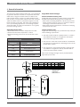
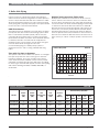
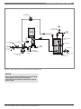
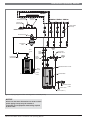
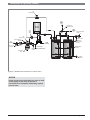
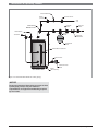
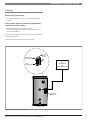
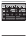
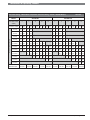
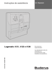
Indirect Fired Water Heaters
Installation and Operating Manual
®
C
Models: SST150-40
SST250-65
SST300-80
SST450-119
US
CAUTION
The heat transfer medium must be water or other nontoxic fluid
having a toxicity rating or class of 1, as listed in Clinical
Toxicology of Commercial Products, 5th edition.
The pressure of the heat transfer medium must be limited to a
maximum of 30 PSIG by an approved safety or relief valve.
WARNING
This manual must only be used by a trained heating installer /
service technician. Read all instructions before installing.
Perform steps in the order given. Failure to comply could result
in severe personal injury, death, or substantial property
damage.
Installation & Operating Manual
2 |
Indirect Fired Water Heaters Installation and Operating Manual
Installation & Operating Manual
Table of Contents
1 General Information
6
2 Pre-installation
7
3 Boiler Side Piping
8
4 Domestic Side (Tank) Piping
13
5 Wiring
17
6 Start-up and Check-out
18
7 Maintenance
19
8 Performance Data
21
Limited Lifetime Warranty
25
Indirect Fired Water Heaters Installation and Operating Manual
|3
Installation & Operating Manual
Hazard Definitions
The following defined terms are used throughout this
manual to bring attention to the presence of hazards of
various risk levels or to important information concerning
the life of the product.
DANGER
DANGER indicates an imminently hazardous situation
which, if not avoided, will result in death or serious
injury.
WARNING
WARNING indicates a potentially hazardous situation
which, if not avoided, could result in death or serious
injury.
CAUTION
CAUTION indicates a potentially hazardous situtation
which, if not avoided, may result in minor or
moderate injury.
CAUTION
CAUTION used without the safety alert symbol
indicates a potentially hazardous situation which, if
not avoided, may result in property damage.
NOTICE
NOTICE indicates special instructions on installation,
operation, or maintenance that are important but not
related to personal injury or property damage.
4 |
Indirect Fired Water Heaters Installation and Operating Manual
Installation & Operating Manual
Please Read Before Proceeding
WARNING
Installer – Read all instructions before installing.
Perform steps in the order given. Have this indirect
water heater serviced/inspected by a qualified
service technician, at least annually. Failure to comply
with the above could result in severe personal injury,
death or substantial property damage.
NOTICE
When calling or writing about the appliance
– Please have the indirect water heater model and
serial number from the indirect water heater rating
plate.
– Consider piping and installation when determining
appliance location.
– Any claims for damage or shortage in shipment
must be filed immediately against the
transportation company by the consignee.
– Factory warranty does not apply to appliances
improperly installed or improperly operated.
DANGER
If the information in this manual is not followed
exactly, a fire or explosion may result causing
property damage, personal injury or loss of life.
This appliance MUST NOT be installed in any location
where gasoline or flammable vapors are likely to be
present.
WHAT TO DO IF YOU SMELL GAS
• Do not try to light any appliance.
• Do not touch any electric switch; do not use any
phone in your home/building.
• Evacuate the home/building immediately.
• Immediately call your gas supplier. Follow the gas
supplier’s instructions.
• If you cannot reach your gas supplier, call the fire
department.
• Installation and service must be performed by a
qualified installer, service agency, or the gas
supplier.
When Servicing the Indirect Water Heater -
To avoid severe burns, allow the appliance to cool
before performing maintenance.
Indirect water heater operation –
HOT WATER CAN SCALD!
• Water heated to temperatures for
clothes washing, dish washing, and other
sanitizing needs can scald and cause
permanent injury.
• Children, elderly, and infirm or physically handicapped
persons are more likely to be permanently injured by
hot water. Never leave them unattended in a bathtub or
shower. Never allow small children to use a hot water
tap or draw their own bath.
• If anyone using hot water in the building fits the above
description, or if state laws or local codes require
certain water temperatures at hot water taps, you must
take special precautions:
• Use lowest possible temperature setting.
• Install some type of tempering device, such as an
automatic mixing valve, at hot water tap or water
heater. Automatic mixing valve must be selected and
installed according to valve manufacturer’s
recommendations and instructions.
• Water passing out of drain valves may be extremely
hot. To avoid injury:
• Make sure all connections are tight.
• Direct water flow away from any person
• Protection Must Be Taken Against Excessive
Temperature and Pressure! Installation of a
Temperature & Pressure (T&P) relief valve is required.
WARNING
Should overheating occur or gas supply fail to shut off, do
not turn off or disconnect electrical supply to circulator.
Instead, shut off the gas supply at a location external to
the appliance.
Do not use this appliance if any part has been under
water. The possible damage to a flooded appliance can be
extensive and present numerous safety hazards. Any
appliance that has been under water must be replaced.
The following chart details the relationship of water
temperature and time with regard to scald injury and may
be used as a guide in determining the safest water
temperature for your applications.
APPROXIMATE TIME / TEMPERATURE
RELATIONSHIPS IN SCALDS
120° F
More than 5 minutes
125° F
1 ½ to 2 minutes
130° F
About 30 seconds
135° F
About 10 seconds
140° F
Less than 5 seconds
145° F
Less than 3 seconds
150° F
About 1 ½ seconds
155° F
About 1 second
Failure to adhere to the guidelines on this page can
result in severe personal injury, death, or substantial
property damage.
Indirect Fired Water Heaters Installation and Operating Manual
|5
Installation & Operating Manual
1 General Information
The SST series indirect water heater (FIG. 1-1) is designed
to generate domestic hot water in conjunction with a hot
water boiler using forced boiler water circulation. This
indirect water heater consists of a 316L Stainless Steel
tank in which a smooth 304L stainless steel coil is located
(Table 1A). Boiler water is pumped through the coil and
heats the water in the tank. This tank is not intended for
use in pool heating applications or for heating any fluid
other than water. It is also not intended for use in gravity
hot water heating systems.
Single-Wall Heat Exchanger
Operating Restrictions:
Uniform Plumbing Code
Single-wall heat exchangers are permitted if they satisfy all
of the following requirements:
National Standard Plumbing Code
Single-wall heat exchangers in water heaters comply with
the National Standard Plumbing Code provided that:
• boiler water (including additives) is practically non-toxic,
having a toxicity rating or class of 1, as listed in Clinical
Toxicology of Commercial Products, and
• boiler water pressure is limited to a maximum of 30 psig
by approved relief valve.
• Maximum domestic hot water temperature is 194°F.
• Maximum boiler water temperature is 210°F.
• Maximum working pressure for the vessel tank is 150
psig.
Component Materials
1. The heat transfer medium is potable water or contains
only substances which are recognized as safe by the
U.S. Food and Drug Administration.
Table 1A
Component
Material
Tank
316L Steel Stainless Steel
Coil
304L Stainless Steel
Insulation
Polyurethane
Jacket
Polypropylene/ABS
“F”
PART NO.
SST150-40
2. The pressure of the heat transfer medium is maintained
less than the normal minimum operating pressure of the
potable water system.
3. The equipment is permanently labeled to indicate that
only additives recognized as safe by the FDA shall be
used in the heat transfer medium.
Other heat exchanger designs may be permitted where
approved by local code.
“A”
“B”
“C”
“D”
“E”
“F”
(in.)
(in.)
(in.)
(in.)
(in.)
(in.)
3
3 1/4
8 1/4
9 1/4
25 1/4
28
48 1/2
52 1/2
56
60
20
70
69
SST250-65
SST300-80
3 1/4
9 1/4
28
61 3/4
SST450-119
3 1/4
9 1/4
31 3/4
60 1/4
NOTES:
1. 1” NPT ON SST150-40.
22.5°
WEIGHT
FULL OF WATER
(lbs.)
24
515
820
24
921
28
1268
1. RELIEF VALVE CONNECTION
2. HOT WATER OUTLET
3. BOILER WATER IN
4. BOILER WATER OUT
5. DRAIN/COLD WATER INLET
45°
1-1/2” NPT (SEE NOTE 1) 2
3/4” NPT 1
1” NPT 3
“E”
“D”
AQUASTAT/SENSOR WELL
1” NPT 4
“C”
1-1/2” NPT (SEE NOTE 1) 5
“B”
“A”
SST150 - SST450
Figure 1-1
6 |
Indirect Fired Water Heaters Installation and Operating Manual
Installation & Operating Manual
2 Pre-installation
1. The installation must conform to the instructions in this
manual and all applicable local, state, provincial, and
national codes, laws, regulations, and ordinances.
Installations in Canada must conform to B149.2
Installation Code.
2. Be certain the domestic water supply to the tank has
physical and chemical characteristics that fall within the
limits shown in Table 2A. Where questions exist as to
the composition of the water on the job, a qualified
water treatment expert should be consulted.
CAUTION
Water with characteristics outside the limits shown in
Table 2A may severely shorten the life of the tank due
to corrosion. Damage to tanks in such cases is not
covered under warranty.
3. Read and understand all installation requirements in
this manual.
Water Chemistry Requirements
Table 2A
Water used in the tank must have characteristics falling
within the following limits:
Characteristic
Min.
Max.
Ph
6.0
8.0
Chloride (PPM)
--
80
Locating the Tank
1. Choose a location for your water heater centralized to
the piping system. You must also locate the SST water
heater where it will not be exposed to freezing
temperatures. Additionally, you will need to place the
water heater so that the controls, drain, and inlet/
outlets are easily accessible. This appliance must not be
installed outdoors, as it is certified as an indoor
appliance, and must also be kept vertical on a level
surface.
2. Keep distance between boiler and water heater to a
minimum to:
a. reduce piping heat loss
b. provide minimal friction loss
3. Figure 1-1 on page 6 shows the weights of all the tanks
filled with water. Make sure that the location chosen for
the tank is capable of supporting it.
CAUTION
This appliance must be placed where leakage from
the temperature and pressure (T&P) relief valve,
leakage from the related piping, or leakage from the
tank or connections, will not result in damage to the
surrounding areas, or to the lower floors of the
building. A water heater should always be located in
an area with a floor drain or installed in a drain pan
suitable for water heaters. The manufacturer shall not
be held liable for any such water damage. Damage
caused by the failure to properly install a drain pan or
in an area with a drain is not the responsibility of the
manufacturer or Bosch Thermotechnology Corp.
(BTC).
4. The tank may be located some distance from the boiler
provided the pump is designed to provide the flow
called for in Table 3B - Pressure Drop Values, through
the coil. Also, the further the tank is from the boiler, the
longer the response of the boiler will be to a call from
the tank zone. Insulate piping between the boiler and
the tank.
WARNING
Failure to properly support the tank could result in
property damage or personal injury.
Recommended Clearances
The installation location must provide adequate clearances
for servicing and proper operation of the water heater. A
12 inch vertical clearance is recommended from the top of
the water heater. A zero clearance is allowed for the sides
of the water heater. However, boiler and servicing
clearances must be figured when locating the water
heater.
Indirect Fired Water Heaters Installation and Operating Manual
|7
Installation & Operating Manual
3 Boiler Side Piping
Figures 3-1 thru 3-4 show typical boiler side piping for
several common situations. Regardless of which system is
used it is imperative that the flow rates called for in Table
3B are developed through the coil. This requires properly
sized piping and a properly sized pump. The system shown
in FIG’s 3-1 thru 3-4 are described below:
DHW Prioritization
This piping system is designed to provide direct hot water
priority over the other zones in the heating system. When
there is a Domestic Hot Water (DHW) call for heat, the
controller will shut off the boiler circulator and activate
the domestic hot water circulator. Once the DHW demand
is satisfied, the boiler circulator will be readjusted as
demand requires. The circulator must be large enough to
move the boiler water through the coils. The
recommended piping for a DHW priority system is
depicted in FIG. 3-1 and 3-2 using a GB142 wall hung
boiler.
Multiple Tank Connections (Boiler Side)
Multiple tank installations must be done in the “reversereturn” manner. The reason for this is to create the same
pressure drop (and therefore, the same flow) through the
coil of each tank. The boiler manifold piping must be sized
so that each coil has the flow rate called for in Table 3B.
Because the pressure drop through tank coils varies from
size to size, it is hard to predict the flow rate that will be
developed through each coil when two tanks of different
sizes are placed in the same manifold. For this reason it is
best not to mix tanks of different sizes in the same zone if
their recovery is critical. A sample system is shown in FIG.
3-4.
Pressure Drop Chart
Zone with Circulator to Aquastat
Head Loss (Ft. of Hd.)
This system is like the circulator zone system on a straight
heat job except that one of the zones goes to the tank
instead of radiation. As on any circulator zone system
check valves should be installed in each zone to prevent
unwanted circulation through zones which are not calling
for heat. Figure 3-3 illustrates typical circulator zone piping
with a floor standing G115WS, G125BE, GB125BE, or
G215 boiler.
Table 3A
12
SST450-119
10
SST250-65/
SST300-80
8
SST150-40
6
4
2
0
0
5
8
12
16
20
Flow Rate
.
Pressure Drop Values
Table 3B
Model
Water
Inlet
(IN)
Water
Outlet
(IN)
Coil
Connection
(IN)
Coil
Length
(FT)
Surface
area
(SQ-FT)
SST150-40
1
1
1
30.8
SST250-65
1.5
1.5
1
SST300-80
1.5
1.5
SST450-119
1.5
1.5
8 |
Pressure Drop (FT/HD)
5
GPM
8
GPM
12
GPM
16
GPM
20
GPM
10.0
0.41
1.04
2.34
4.16
6.49
41.5
13.5
0.61
1.57
3.53
6.27
9.80
1
41.5
13.5
0.61
1.57
3.53
6.27
9.80
1
67.3
22.0
0.73
1.87
4.22
7.50
11.71
Indirect Fired Water Heaters Installation and Operating Manual
Installation & Operating Manual
AIR
SEPARATOR
ANTI-SCALD
MIXING VALVE
HOT
WATER
OUT
GB 142
BOILER
COLD
WATER
IN
DHW
TANK
PUMP
SYSTEM SUPPLY
SENSOR
PRESSURE RELIEF
VALVE
AIR
SEPARATOR
TANK SENSOR
TO
SYSTEM
BALL VALVE
(TYPICAL)
FROM
SYSTEM
SYSTEM
PUMP
CHECK VALVE
DRAIN
POINT
Y-STRAINER
(RECOMMENDED)
EXPANSION
TANK
SST series tank
RECIRCULATION
PUMP
DRAIN
( FIELD SUPPLY )
Figure 3-1 GB142 Boiler Low Loss Header piping and DHW priority
NOTICE
Please note that these illustrations are meant to show
system piping concept only, the installer is
responsible for all equipment and detailing required
by local codes.
Indirect Fired Water Heaters Installation and Operating Manual
|9
Installation & Operating Manual
ZONE #1
PRESSURE
REDUCING VALVE
PRESSURE
GAUGE
ZONE #2 ZONE #3 ZONE #4
BACKFLOW
PREVENTER
ZONE PUMPS
(TYPICAL)
MAKE UP WATER
AIR SEPARATOR
EXPANSION
TANK
HOT
WATER
OUT
ANTI-SCALD
MIXING VALVE
GB 142
BOILER
COLD
WATER
IN
CHECK VALVE
PUMP
PRESSURE RELIEF VALVE
BALL VALVE
DRAIN
POINT
TANK SENSOR
Y-STRAINER
(RECOMMENDED)
RECIRCULATION
PUMP
CHECK VALVE
SST series tank
DRAIN
( FIELD SUPPLY )
Figure 3-2 Piping diagram zoned with circulators and DHW priority
NOTICE
Please note that these illustrations are meant to show
system piping concept only, the installer is
responsible for all equipment and detailing required
by local codes.
10 |
Indirect Fired Water Heaters Installation and Operating Manual
Installation & Operating Manual
ZONE #1
PRESSURE
REDUCING VALVE
PRESSURE
GAUGE
ZONE #2 ZONE #3 ZONE #4
BACKFLOW
PREVENTER
ZONE PUMPS
(TYPICAL)
MAKE UP WATER
AIR SEPARATOR
EXPANSION
TANK
BALL
VALVE
HOT
WATER
OUT
DHW
TANK
PUMP
ANTI-SCALD
MIXING VALVE
COLD
WATER
IN
FLOW
CHECK
VALVE
Y-STRAINER
(RECOMMENDED)
PRESSURE RELIEF VALVE
BALL
VALVE
G115WS/G125BE/GB125BE
DRAIN
POINT
TANK SENSOR
RECIRCULATION
PUMP
CHECK VALVE
SST series tank
DRAIN
( FIELD SUPPLY )
Figure 3-3 Piping diagram of floor standing boiler and DHW priority
NOTICE
Please note that these illustrations are meant to show
system piping concept only, the installer is
responsible for all equipment and detailing required
by local codes.
Indirect Fired Water Heaters Installation and Operating Manual
| 11
Installation & Operating Manual
AIR
SEPARATOR
HOT
WATER
OUT
GB 142
BOILER
ANTI-SCALD
MIXING VALVE
COLD
WATER
IN
DHW
TANK
PUMP
RECIRCULATION
PUMP
AIR
SEPARATOR
CHECK VALVE
SYSTEM SUPPLY
SENSOR
TO
SYSTEM
BALL VALVE
(TYPICAL)
PRESSURE
RELIEF VALVE
(TYPICAL)
FROM
SYSTEM
SYSTEM
PUMP
DRAIN
POINT
TANK SENSOR
(TYPICAL)
Y-STRAINER
(RECOMMENDED)
EXPANSION
TANK
SST series tank
SST series tank
DRAIN
( FIELD SUPPLY )
Figure 3-4 Multiple tank connections in reverse return
NOTICE
Please note that these illustrations are meant to show
system piping concept only, the installer is
responsible for all equipment and detailing required
by local codes.
12 |
Indirect Fired Water Heaters Installation and Operating Manual
Installation & Operating Manual
4 Domestic Side (Tank) Piping
Basic Domestic Piping
Figure 4-2 shows typical domestic water piping for a tank.
The function of the components shown are as follows:
a. Shut-off valves (recommended) - Used to isolate the
tank for servicing.
b. Backflow Preventer (required by some codes) Used to prevent water from backing out of the tank in
the event that inlet water pressure drops.
c. Expansion Tank (required when a backflow
preventer is used) - This expansion tank absorbs the
increased volume caused by heating water.
Use an expansion tank designed for use on domestic
water systems. Refer to the expansion tank
manufacturer’s literature for the proper size expansion
tank to use.
NOTICE
If an expansion tank is used, do not put any valves
between the expansion tank and tank inlet.
d. Unions (optional) - Used to disconnect the tank in the
unlikely event that this is necessary.
Domestic Water Piping for Distant Fixtures
In some cases the furthest fixture may be quite distant
from the tank. Such an installation would result in an
unacceptable delay before hot water reaches these distant
fixtures. Even if all the fixtures are relatively close to the
tank, the building owner may want hot water at all fixtures
as soon as they are opened.
A solution to this problem is that a pipe runs from the
furthest fixture on each branch back to the return of the
tank (reference FIG. 4-2). A small DHW recirculation pump
is mounted in this line and is wired so as to run
continuously. A check valve in this line permits flow
towards the tank inlet only.
When no fixtures are drawing water, the DHW recirculation
pump moves hot water from the tank to the end of the
branch just below the last fixture, then back to the inlet of
the tank via the return pipe. When a fixture is opened, hot
water is already out in the branch very close to the fixture
and hot water appears at it almost immediately. The check
valve prevents cold water in the tank’s inlet pipe from
passing around the tank and heading directly to the fixture.
Because hot water is always circulating in the hot water
branch the entire branch should be insulated to prevent
excessive heat loss.
e. Drain (required) - Used to drain the tank for inspection
or servicing.
Multiple Tank Domestic Water Piping
The two pipe reverse return piping uses more pipe than
the two pipe direct return piping, but the flow is more
balanced and even in the two pipe reverse return piping
layout (see FIG. 3-4).
Each tank must have its own T&P valve. It is recommended
that each tank be equipped with its own isolation valves,
unions, and drains so that one tank may be removed from
the system. If local codes require a backflow preventer,
check with the appropriate authority to find out whether
one backflow preventer may be used for tanks or each tank
must be equipped with its own backflow preventer. If each
tank must have its own backflow preventer, each tank must
also have its own expansion tank. If a common backflow
preventer is permitted, an expansion tank must be sized to
accommodate the expansion volume of all tanks.
Indirect Fired Water Heaters Installation and Operating Manual
| 13
Installation & Operating Manual
Anti-scald Valves (Mixing Valves)
Anti-scald valves used with water heaters are also called
tempering valves or mixing valves. An anti-scald valve
mixes cold water in with the outgoing hot water to assure
that hot water reaching a building fixture is at a
temperature low enough to be safe.
Usually, the maximum temperature of the outlet water will
stay near the setting of the tank control. In some cases,
however, hot water usage patterns can cause the outlet
water temperature to rise significantly above the control
setting.
The temperature of water going to the fixtures may be
more carefully controlled through the use of a
thermostatic mixing valve. This device blends a controlled
amount of cold water with the hot water leaving the tank
so that water at a more constant temperature exits the
mixing valve. Anti-scald mixing valve piping is illustrated in
FIG.’s 3-1 thru 3-4.
WARNING
An anti-scald mixing valve does not eliminate the risk
of scalding.
* Set the tank thermostat as low as practical.
* Feel water before bathing or showering.
* If anti-scald or anti-chill protection is required, use
devices specifically designed for such service. Install
these devices in accordance with their
manufacturer’s instructions.
Install Drain Valve
Drain valve and fittings are supplied by others.
Standard Installation
• Install a tee connection at the domestic cold water inlet
(FIG. 4-1).
Temperature & Pressure (T&P) Relief Valve
WARNING
For protection against excessive temperatures and
pressure, install temperature and pressure
protective equipment required by local codes, but
not less than a combination temperature and
pressure (T&P) relief valve certified by a nationally
recognized testing laboratory that maintains periodic
inspection of production of listed equipment or
materials as meeting the requirements for Relief
Valves and Automatic Gas Shutoff Devices for Hot
Water Supply Systems, ANSI Z21.22 and the
Standard CAN1-4.4, Temperature, Pressure,
Temperature and Pressure Relief Valves and Vacuum
Relief Valves. The combination temperature and
pressure relief valve shall be marked with a
maximum set pressure not to exceed the maximum
working pressure of the water heater. The
combination temperature and pressure relief valve
shall also have an hourly rated temperature steam
BTU discharge capacity not less than shown in
Table 4A.
Install the combination temperature and pressure
relief valve into the opening provided and marked for
this purpose on the water heater. Failure to properly
install the correct temperature and pressure (T&P)
relief valve can result in a discharge of hot water
that can cause severe personal injury or substantial
property damage.
NOTICE
Verify that the combination temperature and pressure
(T&P) relief valve complies with local codes. If the
combination temperature and pressure relief valve
does not comply with local codes, replace it with one
that does. Follow the installation instructions in this
section.
DRAIN
VALVE
Figure 4-1 Drain valve installed
14 |
Indirect Fired Water Heaters Installation and Operating Manual
Installation & Operating Manual
Do not place a valve between the combination temperature
and pressure relief valve and the tank.
Standard Installation
• Install the T&P relief valve in the connection marked
“Relief Valve”.
Determine T&P relief valve size by the following
specifications, unless they conflict with local codes:
T&P Relief Valve Discharge Piping
T&P relief valve discharge piping must be:
- made of material serviceable for a temperature of
250°F or greater.
- directed so that hot water flows away from all persons.
- directed to a suitable place for disposal.
- installed so as to allow complete draining of the T&P
relief valve and discharge line.
- terminated within 6” of the floor.
- SST150-40 - 3/4” NPT with a minimum AGA Rating of
105,000 Btu/hr.
- SST250-65/300-80/450-119 - 3/4” NPT with a
minimum AGA Rating of 200,000 Btu/hr.
NOTICE
The SST series water heaters will absorb/store less
than 200,000 Btu/hr when domestic water outlet
temperature is 210°F and boiler water supply
temperature is 240°F. Listed outputs are based on
ASME Section VIII Interpretation VIII-1-86-136. Check
with local codes for applicability.
Minimum Relief Valve (AGA Rating)
Table 4A
Model
BTU/hr
SST150-40
105,000
SST250-65
200,000
SST300-80
200,000
SST450-119
200,000
T&P relief valve discharge piping must not be:
- excessively long. Using more than two (2) elbows or 15
feet of piping can reduce discharge capacity.
- directly connected to a drain. Refer to local codes.
- subject to freezing.
WARNING
Do not install any valve between the temperature
and pressure (T&P) relief valve and the tank
connection or on the T&P relief valve discharge
piping. Improper placement and piping of T&P relief
valve may result in a discharge of hot water that can
cause severe personal injury, death or substantial
property damage.
CAUTION
The temperature and pressure (T&P) relief valve is
not intended for constant duty, such as relief of
pressure due to repeated normal system expansion.
Correct this condition by installing a properly sized
expansion tank in a domestic water system. Refer to
the expansion tank manufacturer’s installation
instructions for proper sizing. Be advised, the hot
discharge water from the temperature and pressure
(T&P) relief valve, can cause severe personal injury,
or substantial property damage.
WARNING
Failure to install and maintain a new, listed ¾" X ¾"
temperature and pressure (T&P) relief valve will
release the manufacturer from any claim which might
result from excessive temperature and pressures or
discharge of hot water.
Indirect Fired Water Heaters Installation and Operating Manual
| 15
Installation & Operating Manual
SHOCK ARRESTOR
UNION
(TYPICAL)
SHUTOFF VALVE
ANTI-SCALD
MIXING VALVE
SHUTOFF
VALVE
SHUTOFF
VALVE
FROM BOILER
SHUTOFF
VALVE
TO BOILER
BACKFLOW
PREVENTER
EXPANSION
TANK
TANK SENSOR / AQUASTAT
CHECK VALVE
RECIRCULATION
PUMP
SST SERIES TANK
DRAIN
( FIELD SUPPLY)
Figure 4-2 Recommended domestic water piping
NOTICE
Please note that these illustrations are meant to show
system piping concept only, the installer is
responsible for all equipment and detailing required
by local codes.
16 |
Indirect Fired Water Heaters Installation and Operating Manual
Installation & Operating Manual
5 Wiring
Wiring using boiler sensor:
1. For wiring using boiler sensor, see boiler installation
manual.
Indirect Water Heater Controlled Using Aquastat
and Zone Circulator / Valve:
1. Install Aquastat to tank. Aquastat control
(Honeywell L4006 or equivalent) can be ordered from
your local distributor.
2. Connect Aquastat to the zone controller for the Indirect
Water Heater Zone.
3. Adjust Aquastat to the desired temperature.
Honeywell
L4006 or
equivalent
TEMPERATURE
ADJUSTMENT
ZONE CONTROL BOX
OR
ZONE VALVE
OR
ZONE CIRCULATOR
WIRE
CONNECTIONS
AQUASTAT
CONTROL
INDIRECT TANK
Figure 5-1 Wiring for zone control
Indirect Fired Water Heaters Installation and Operating Manual
| 17
Installation & Operating Manual
6 Start-up and Check-out
1. Make sure the system is free of leaks and that air is
purged from the system.
CAUTION
Fix any leaks found before proceeding further.
Leakage from the boiler piping can result in severe
damage to the boiler.
2. Many soldering fluxes contain Zinc Chloride which can
cause severe corrosion damage to stainless steel. After
completing all domestic water connections, flush the
indirect water heater thoroughly before leaving the
installation. This is particularly important if the indirect
water heater will be unused for an extended period of
time after installation. Flush the indirect water heater by
drawing at least three times its volume from the tank.
3. Make sure that all electrical connections are made
correctly and that no exposed high voltage wiring is
present.
4. Make sure that each zone valve or circulator operates
when, and only when, its thermostat calls for heat. Let
each zone operate long enough to purge any remaining
air from the system.
5. Set the indirect water heater to the desired
temperature. Because hot water presents a scald
hazard, it is best to set the thermostat at 120°F or lower
and raise it only if necessary to provide adequate hot
water.
6. Re-enable the burner and allow the boiler to operate.
Make sure that the boiler shuts down when the indirect
water heater is satisfied.
18 |
Indirect Fired Water Heaters Installation and Operating Manual
Installation & Operating Manual
7 Maintenance
The SST series indirect water heater is an extremely
simple device and as such requires very little maintenance.
There are, however, several items which should be
checked out on an annual or as needed basis to ensure a
reliable supply of hot water:
5.
• Make sure that the rest of the boiler and domestic water
piping is free of leaks.
1.
• The indirect water heater depends upon the boiler for a
source of heat and is therefore only as reliable as the
boiler.
• Make sure that the boiler is maintained in accordance
with the boiler manufacturer’s instructions.
• If a water treatment system is required to keep the water
chemistry within the parameters shown in Table 2A (see
Section 2 - Pre-Installation), make sure that this system
is properly maintained.
Maintenance Schedule
Annual service by a qualified service technician should
include the following:
1.
2.
3.
4.
Review homeowner’s maintenance responsibilities
and their frequencies, including any not listed in the
following section.
Homeowner monthly maintenance to include:
Visually check valves, pipes, and fittings for leaks. Call
a qualified service technician to repair leaks.
To Fill the Water Heater
1. Close the water heater drain valve by turning the knob
clockwise.
2. Open the cold water supply shutoff valve. Open
several hot water faucets to allow air to escape from
the system.
3. When a steady stream of water flows from the faucets,
the water heater is filled. Close the faucets and check
for water leaks at the water heater drain valve,
combination temperature and pressure relief valve and
the hot and cold water connections.
Any procedure required by local codes.
Verify system pressure. Air venting procedure may
require adding water to bring boiler system up to
pressure, typically 12 psig.
Manually operate T&P relief valve at least once a year.
This will release some hot water.
WARNING
Water from opened drain valves, unions and other
connections may be extremely hot. To avoid severe
personal injury, death, or substantial property
damage:
- Tighten all drain hose connections.
- Direct hot water away from all persons.
WARNING
Before operating a temperature and pressure (T&P)
relief valve, make sure no one is in front of or around
the T&P relief valve discharge piping. Hot discharge
water can cause severe personal injury or substantial
property damage.
4.
Move operating lever to open position for a few
seconds and then move it back, allowing it to snap
closed. After the T&P relief valve is operated, if it
continues to release water, close the cold water inlet
to the water heater immediately. Follow the draining
instructions, and replace the T&P relief valve. If the
T&P relief valve weeps periodically, it may be due to
thermal expansion. Do not plug the T&P relief valve or
discharge piping.
DANGER
Plugging the temperature and pressure (T&P) relief
valve or discharge piping can cause excessive
pressure in the water heater, resulting in severe
personal injury, death, or substantial property
damage.
Indirect Fired Water Heaters Installation and Operating Manual
To Drain the Water Heater
Should it become necessary to completely drain the water
heater, be sure to follow the steps below:
1. Disconnect the power supply to the heat source.
Consult the plumbing professional or electric company
in your area for service.
2. Close the cold water supply shutoff valve.
3.
Open the drain valve on the water heater.
4.
Open a hot water faucet to allow air to enter the
system.
Drain the water heater if it will be shut off and exposed to
freezing temperatures. Freezing water will expand and
damage the water heater.
• If boiler water contains sufficient antifreeze, then only
the domestic water needs to be drained.
• If boiler water does not contain sufficient antifreeze, the
boiler water and the domestic water must be drained.
If antifreeze is used in the boiler water, check
concentration. Boiler water (including additives) must be
practically non-toxic, having a toxicity rating or class of 1,
| 19
Installation & Operating Manual
as listed in the “Clinical Toxicology of Commercial
Products”. A maximum 50/50 mixture of inhibited
propylene glycol is recommended. Follow the antifreeze
manufacturer’s instructions.
WARNING
Do not use automotive, ethylene glycol or
petroleum-based antifreeze. These types of
antifreezes are toxic and could cause severe
personal injury or death if leakage into the domestic
hot water supply occurs. Do not use any undiluted
antifreeze. This can cause severe personal injury,
death, or substantial property damage.
20 |
Indirect Fired Water Heaters Installation and Operating Manual
Installation & Operating Manual
8 Performance Data
Indirect Water Heater I=B=R Rating
Table 8A
Potable
Water
Volume
Gal.
Heat
Source
Water
Volume
Gal.
Standby
Heat Loss
F/hr
Continuous
Draw
Rating
Gal/hr
First
Hour
Rating
Gal/hr
Minimum
Heat Output
Rate from
Heat Source
Btu/hr
Minimum
Heat
Source
Flow Rate
GPM
Tank Heat
Source
Friction
Loss Feet
W.C
SST150-40
40.0
1.6
0.9
181
208
115,000
14.0
4.5
SST250-65
67.0
1.9
0.7
263
327
154,000
14.0
5.7
SST300-80
81.5
2.1
0.6
285
358
171,000
14.0
6.1
SST450-119
113.4
3.2
0.5
349
459
216,000
14.0
6.5
Model
• These ratings were obtained with a heat source output and
heat source flow rate as listed in the chart using the
parameters of the Domestic Cold Water Inlet at 58°F,
Domestic Temperature Rise of 77°F, and a Boiler
Temperature Output of 180°F. Other results will be
obtained under different conditions.
Indirect Fired Water Heaters Installation and Operating Manual
| 21
Installation & Operating Manual
How to Properly Size Your Indirect Water Heater
Use the First Hour Rating (FHR) to properly size your
Indirect Water Heater. The First Hour Rating is the amount
of hot water in gallons the heater can supply per hour
(starting with a tank full of hot water), depending on tank
capacity, source of heat, and the size of the burner.
Estimate your peak hour demand as follows:
• Determine what time of day (morning, noon, evening) you
use the most hot water in your home. Keep in mind the
number of people living in your home.
• Use the worksheet below to estimate your maximum
usage of hot water during this one hour of the day -- this
is your peak hour demand. Note: The worksheet does not
estimate total daily hot water usage.
The worksheet example shows a total peak hour demand
of 165 gallons; therefore, this household would need a
water heater with a First Hour Rating of no less than 165
gallons.
Fixture Count Guide
To quickly estimate the minimum gallons of hot water
required based on a family size number of baths and hot
water appliances the First Hour Rating of the STS tank
must be equal to or exceed the total first hour
requirements.
Peak Hour Demand Worksheet
Description
Fill in the Blank
Example
40 Gallons for the first 2 people
___________________________
Gals.
40
Gals.
10 Gallons for each additional person
___________________________
Gals.
20
Gals.
20 Gallons for each bath after the first
___________________________
Gals.
20
Gals.
10 Gallons if dishwasher is used
___________________________
Gals.
10
Gals.
20 Gallons if clothes washer is used
___________________________
Gals.
20
Gals.
TOTAL
___________________________
Gals.
110
Gals.
(consecutive bath)
Heavy Usage Buffer
x 1.5
x 1.5
Use if family members take longer than average showers, etc.
First Hour Rating
___________________________
Gals.
165
Gals.
Proceed to pages 23 & 24 of this manual to locate your
Indirect Water Heater and Boiler in the sizing charts. Using
the First Hour Rating calculated in this worksheet, locate
your Indirect Water Heater and Boiler along with your First
Hour Rating. This will also determine the flow needed
between the Indirect Water Heater and Boiler.
22 |
Indirect Fired Water Heaters Installation and Operating Manual
Installation & Operating Manual
First Hour Rating - 180°F Boiler Loop Water (Universal Sizing - 45,000 - 295,000 Btu/hr)
Model
SST150-40
Circulator Flow
(GPM)
Boiler Heating Capacity
Domestic Outlet
5
8
SST250-65
12
115
140
115
140
45,000
122
97
122
60,000
150
118
75,000
179
95,000
115,000
115
140
20
115
5
140
8
12
140
115
140
97
153
128
153
128
150
118
183
149
183
149
138
179
138
213
170
213
170
217
165
217
165
217
165
252
197
252
217
165
252
189
252
189
252
189
291
226
252
189
267
200
282
211
286
208
305
267
200
282
211
286
213
305
165,000
140
16
115
140,000
115
Table 8B
16
115
140
197
252
197
291
226
291
235
319
245
235
319
319
195,000
115
140
226
291
226
338
259
338
245
356
271
245
356
356
225,000
20
115
140
259
338
259
386
293
388
294
271
386
293
388
294
271
386
293
388
294
388
294
260,000
295,000
Max BTU Input
92,998
112,972
123,331
129,574
Indirect Fired Water Heaters Installation and Operating Manual
132,764
118,488
129,139
146,864
163,768
167,924
| 23
Installation & Operating Manual
First Hour Rating - 180°F Boiler Loop Water (Universal Sizing - 45,000 - 295,000 Btu/hr)
Model
SST300-80
Circulator Flow
(GPM)
Boiler Heating Capacity
Domestic Outlet
5
8
SST450-119
12
115
140
115
140
45,000
163
138
163
60,000
193
159
75,000
222
95,000
115
140
20
140
8
12
115
140
138
197
172
197
172
193
159
226
193
226
193
180
222
180
255
213
255
213
261
207
261
207
261
207
294
241
294
115,000
300
235
300
235
300
235
300
235
333
268
140,000
304
238
347
268
347
268
347
268
347
268
384
165,000
304
238
349
270
374
288
395
302
395
302
387
349
270
374
288
409
312
424
323
374
288
409
312
424
323
424
323
260,000
115
5
140
225,000
140
16
115
195,000
115
Table 8C
16
115
140
115
140
241
294
241
333
268
333
268
333
268
302
382
302
382
302
382
306
429
337
429
337
483
375
485
501
115
140
302
382
302
429
337
429
337
376
485
376
485
376
388
548
421
541
416
573
438
596
454
596
454
295,000
Max BTU Input
24 |
115,860
139,106
154,002
171,229
181,544
141,419
190,161
20
204,795
237,649
253,504
Indirect Fired Water Heaters Installation and Operating Manual
Installation & Operating Manual
Limited Lifetime Warranty For Domestic Hot Water
Stainless Steel Tank Installed In A Residential Application
MODELS COVERED
This limited warranty is provided by Bosch Thermotechnology Corp.
(BTC) and covers indirect stainless steel storage tanks installed in a
one or two family residential dwelling (hereinafter referred to as
“Tank”). This warranty is provided to the original purchaser of the
Tank as long as the Tank remains installed at its original place of
installation, subject to the conditions on Page 2.
WARRANTY COVERAGE
First Ten Years –Limited Warranty
BTC warrants that the heat exchanger and tank assembly will
remain free of leaks for ten years from the date of original installation provided that the Tank is properly maintained by a qualified
heating contractor and the other conditions of this warranty are met.
If during this time BTC determines that the leak is the result of a
defect in workmanship or materials, BTC, at its option, will repair or
replace the heat exchanger and/or tank. Labor charges are not
included.
Eleventh Year and Beyond– Limited Warranty
Beginning on the eleventh year from the date of original installation
and thereafter, BTC provides a limited pro-rated warranty for defects
in the heat exchanger and/or tank. If BTC determines that the leak is
the result of a defect in workmanship or materials BTC will, at its
option, repair the defective heat exchanger and/or tank or replace it
with the most comparable model available from BTC at the time of
the replacement, provided that the purchaser pays for the
proportionate charge set forth below. The proportionate charge is
based the current list price of the heat exchanger and/or tank
involved in the warranty claim (or the nearest comparable model).
The purchaser is charged a percentage of the list price of the heat
exchanger and/or tank (at the time of the claim) as detailed below.
Years since Installation
11 – 12
Percentage Paid by Purchaser
65
13 – 14
70
15 plus
75
If the heat exchanger is no longer available, BTC will provide a new
residential hot water tank at the then applicable retail price less the
proportionate charge for the heat exchanger as set forth in the table
above (the charge will be calculated using the last list price of the
discontinued heat exchanger). Labor charges are not included.
OTHER HOT WATER SYSTEM COMPONENTS
The Tank may be delivered with other system components not
manufactured by BTC (“Other Components). Other Components are
warranted by the manufacturer. BTC also will warrant the Other
Components to be free from defects in workmanship and material for
one year from the date of installation, provided they are installed and
properly maintained by a qualified heating contractor and the other
conditions of this warranty are met. If a defect exists in the Other
Components, BTC will repair or replace them and pay for the
associated labor charges at BTC approved rates, if BTC determines
that a defect in workmanship or materials exists.
Limited Lifetime Warranty For Domestic Hot Water
Stainless Steel Tank Installed In A Commercial Application
MODELS COVERED
This limited warranty is provided by Bosch Thermotechnology Corp.
(BTC) and covers indirect stainless steel storage tanks installed in
other than a one or two family residential dwelling (hereinafter
referred to as “Tank”). This warranty is provided to the original
purchaser of the Tank as long as the Tank remains installed at its
original place of installation, subject to the conditions on Page 2.
WARRANTY COVERAGE
First Three Years –Limited Warranty
BTC warrants that the Tank will remain free of defects in material
and workmanship for three years from the date of original
installation provided that the Tank is properly maintained by a
qualified heating contractor and the other conditions of this warranty
are met. If during this time BTC determines that the leak is the result
of a defect in workmanship or materials, BTC, at its option, will
repair or replace the defective components and/or tank. Labor
charges are not included.
Effective 06/2011
Indirect Fired Water Heaters Installation and Operating Manual
OTHER HOT WATER SYSTEM COMPONENTS
The Tank may be delivered with other system components not
manufactured by BTC (“Other Components). Other Components are
warranted by the manufacturer. BTC also will warrant the Other
Components to be free from defects in workmanship and material for
one year from the date of installation, provided they are installed and
properly maintained by a qualified heating contractor and the other
conditions of this warranty are met. If a defect exists in the Other
Components, BTC will repair or replace them and pay for the
associated labor charges at BTC approved rates, if BTC determines
that a defect in workmanship or materials exists.
Continued on next page
| 25
Installation & Operating Manual
Additional Terms And Conditions Of The Limited Warranties
For Domestic Hot Water Stainless Steel Tanks
(For All Applications)
ITEMS NOT COVERED
The warranty for Commercial and Residential Domestic Hot
Water Tanks does not cover the following circumstances:
1. Components or parts not provided by BTC.
2. Serviceable items and normal maintenance as required per
the Installation Manual.
3. The workmanship of any installer. BTC disclaims and does not
assume any liability of any nature for unsatisfactory
performance caused by improper installation, repair or
maintenance.
LIMITED WARRANTY
Other than the obligations of BTC expressly set forth herin, BTC
disclaims all warranties, express or implied, including but not
limited to any implied warranties of merchantability or fitness
for a particular purpose. BTC’s sole obligation with respect to the
tank and purchaser’s exclusive remedies are set forth in the
foregoing limited warranty. BTC shall not be liable for any
indirect, punitive, incidental, special, consequential or similar
damages including, without limitation, injury or damage to persons
or property or damages for loss of use, lost profits, inconvenience or
loss of time.
4. Any labor or material costs for removal, reinstallation, repair
and replacement of the defective component or part unless
otherwise provided above.
Note that any repaired or replaced product will be warranted for only
the unexpired term of the original warranty.
5. Transportation to BTC, if necessary.
Some states do not allow the exclusion of limitation of damages, or
limitations on how long an implied warranty lasts, so the above
limitations and exclusions may not apply to you.
6. Damage caused by excessive temperatures or pressures, fuel
or gas explosion, electrochemical reaction, water and air
impurities, electrical failures, flooding or acts of God.
7. Any Tank that has a failure of malfunction resulting from failure
to keep the Tank full of potable water, failure to assure that the
water in the Tank is free to circulate at all times, failure to keep
the Tank free of water sediment or scale deposits or failure to
inspect the Tank at intervals of not more than two years.
8. Shipping charges, delivery expenses or administrative fees
incurred by the purchaser in repairing or replacing the Tank.
CONDITIONS OF WARRANTY
The warranty for Commercial and Residential Domestic Hot Water
Tanks is void under the following circumstances:
1. Any Tank that is installed where polybutylene pipe without an
oxygen barrier is used.
2. Any Tank that is connected to any closed loop application
system that allows oxygen penetration of the system.
3. Failure or malfunction resulting from improper or negligent
operation, accident, abuse, freezing, misuse, unauthorized
alteration or improper installation, repair or maintenance. See
the Owner’s Manual for installation and maintenance
information.
WARRANTY CLAIMS PROCESS
If you have a warranty claim you should notify the heating contractor
who installed your Tank and ask that the contractor notify the
distributor from whom the contractor purchased the Tank. If this
action is not possible or you don’t receive a response, contact Bosch
Thermotechnology Corp., 50 Wentworth Avenue, Londonderry, NH
03053. To process your claim, you will need a copy of your original
invoice or other proof of purchase and documentation showing the
original installation date and location. The alleged defective
components or parts must be returned to BTC in accordance with
BTC procedure then in force for handling goods returned for the
purpose of inspection to determine cause of failure (contact BTC if
you have questions regarding the return process). If BTC determines
that the returned components and/or parts are defective and that this
warranty applies, BTC will furnish the repaired or replacement
components and/or parts to an authorized BTC distributor who, in
turn, will forward the components and/or parts to the heating
contractor who installed your Hot Water Tank.
4. Any Tank that did not have installed a new
temperature/pressure relief valve at the time of installation.
5. Any Tank used with insufficient water or is operated with water
that cause deposits or corrosion.
6. Failure to inspect the Tank at intervals of not more than two
years. See the Owner’s Manual for installation and maintenance information.
7. Work performed without prior authorization or approval and
without authorization/requisition number and without proper
documentation verifying compliance with above terms.
Effective 06/2011
26 |
Bosch Thermotechnology Corp. • 50 Wentworth Avenue • Londonderry, NH 03053
Tel: (603) 552-1100 Fax: (603) 584-1681
Indirect Fired Water Heaters Installation and Operating Manual
Installation & Operating Manual
Indirect Fired Water Heaters Installation and Operating Manual
| 27
United States and Canada
Bosch Thermotechnology Corp.
50 Wentworth Avenue
Londonderry, NH 03053
Tel: 603-552-1100
Fax: 603-584-1681
www.bosch-climate.us
BTC 471003301 B / 06.2011
SST-I-O Rev B