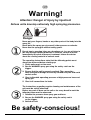
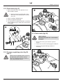
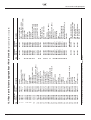
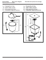
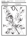
1
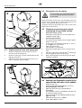
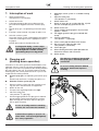
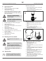
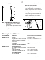
Betriebsanleitung
Operating manual ................. p. 24
Mode d’emploi ...................... p. 48
Istruzioni per l’uso ................ p. 72
Airless Hochdruck-Spritzgerät
Airless high-pressure spraying unit
Groupe de projection à haute pression
Impianto per la verniciatura a spruzzo ad alta pressione Airless
Super Finish 21
Super Finish 23
Super Finish 21 • 23
Ausgabe 02 / 2003
Edition
Edizione
0340 852
g
Warning!
Attention: Danger of injury by injection!
Airless units develop extremely high spraying pressures.
Danger
①
②
Never put your fingers, hands or any other parts of the body into the
spray jet!
Never point the spray gun at yourself, other persons or animals.
Never use the spray gun without safety guard.
Do not treat a spraying injury as a harmless cut. In case of injury to
the skin through coating materials or solvents, consult a doctor
immediately for quick and expert treatment. Inform the doctor
about the coating material or solvent used.
The operating instructions state that the following points must
always be observed before starting up:
1. Faulty units must not be used.
2. Secure WAGNER spray gun using the safety catch on the
trigger.
3. Ensure that the unit is properly earthed. The connection
must take place through a correctly earthed two-pole and earth
socket outlet.
4. Check allowable operating pressure of high-pressure hose and
spray gun.
5. Check all connections for leaks.
③
The instructions regarding regular cleaning and maintenance of the
unit must be strictly observed.
Before any work is done on the unit or for every break in work the
following rules must be observed:
1. Release the pressure from spray gun and hose.
2. Secure the WAGNER spray gun using the safety catch
on the trigger.
3. Switch off unit.
Be safety-conscious!
24
Super Finish 21 • 23
g
Contents
Contents
Page
Page
1.
Safety regulations for Airless spraying. . . 26/27
2.
General view of application . . . . . . . . . . . . 27/28
2.1
Application . . . . . . . . . . . . . . . . . . . . . . . . . .
27
2.2
Coating materials . . . . . . . . . . . . . . . . . . . . .
28
3.
Description of unit . . . . . . . . . . . . . . . . . . . 28-31
3.1
Airless process . . . . . . . . . . . . . . . . . . . . . . .
28
3.2
Functioning of the unit . . . . . . . . . . . . . . . . .
28
3.3
Explanatory diagram. . . . . . . . . . . . . . . . . . . 29/30
3.3.1 Super Finish 21
Vertical set-up with suction system . . . . . . .
29
3.3.2 Super Finish 21
Horizontal set-up with upper hopper . . . . . .
29
3.3.3 Super Finish 23
Vertical set-up with suction system . . . . . . .
30
3.3.4 Super Finish 23
Horizontal set-up with upper hopper . . . . . .
30
3.4
Technical data Super Finish 21 and 23. . . . .
31
3.5
Transport. . . . . . . . . . . . . . . . . . . . . . . . . . . .
31
10.
Servicing . . . . . . . . . . . . . . . . . . . . . . . . . . .
38
10.1 General servicing . . . . . . . . . . . . . . . . . . . . .
38
10.2 High-pressure hose . . . . . . . . . . . . . . . . . . .
38
11.
Repairs on the unit . . . . . . . . . . . . . . . . . . . 38-41
11.1 Inlet valve . . . . . . . . . . . . . . . . . . . . . . . . . . .
38
11.2 Outlet valve . . . . . . . . . . . . . . . . . . . . . . . . . .
39
11.3 Pressure regulating valve . . . . . . . . . . . . . . .
39
11.4 Relief valve . . . . . . . . . . . . . . . . . . . . . . . . . .
39
11.5 Exchanging diaphragm. . . . . . . . . . . . . . . . .
40
11.6 Replace unit connection line . . . . . . . . . . . .
40
11.7 Circuit diagram . . . . . . . . . . . . . . . . . . . . . . .
41
12.
Accessories and spare parts . . . . . . . . . . .
42
12.1 Accessories for Super Finish 21 and 23 . . . .
42
Accessories illustration
for Super Finish 21 and 23 . . . . . . . . . . . . . .
96
12.2 Spare parts list frame Super Finish 21 . . . .
43
12.3 Spare parts diagram frame Super Finish 21 .
43
12.4 Spare parts list trolley Super Finish 23 . . . . .
43
4.
Starting operation . . . . . . . . . . . . . . . . . . . . . . . 31-33
12.5 Spare parts diagram trolley Super Finish 23
43
4.1
Unit with suction system . . . . . . . . . . . . . . .
31
12.6 Spare parts list suction system . . . . . . . . . .
43
4.2
Unit with upper hopper (5 litres) . . . . . . . . . . 31/32
12.7 Spare parts diagram suction system . . . . . .
43
4.3
High-pressure hose and spray gun . . . . . . .
32
12.8 Spare parts list upper hopper 5 litres . . . . . .
44
4.4
Connection to the mains. . . . . . . . . . . . . . . .
32
Spare parts diagram upper hopper 5 litres. .
98
4.5
Cleaning preserving agent when
starting-up of operation initially . . . . . . . . . .
12.9 Spare parts list upper hopper 20 litres . . . . .
44
32
Spare parts diagram upper hopper 20 litres.
98
4.6
Ventilate unit (hydraulic system) if the
sound of the inlet valve is not audible . . . . . 32/33
12.10 Spare parts list pump head
Super Finish 21 and 23. . . . . . . . . . . . . . . . .
44
4.7
Starting operation of unit with coating
material . . . . . . . . . . . . . . . . . . . . . . . . . . . .
33
Spare parts diagram pump head
Super Finish 21 and 23. . . . . . . . . . . . . . . . .
97
4.8
Socket on unit. . . . . . . . . . . . . . . . . . . . . . . .
33
12.11 Spare parts list pump aggregate
Super Finish 21 and 23 . . . . . . . . . . . . . . . .
45
5.
Spraying technique. . . . . . . . . . . . . . . . . . .
33
Spare parts diagram pump aggregate
Super Finish 21 and 23. . . . . . . . . . . . . . . . .
99
6.
Handling the high-pressure hose . . . . . . .
33
6.1
High-pressure hose . . . . . . . . . . . . . . . . . . .
33
7.
Interruption of work . . . . . . . . . . . . . . . . . .
34
8.
Cleaning unit (shutting down operation) . 34-36
8.1
Cleaning unit from outside . . . . . . . . . . . . . .
35
8.2
Suction filter . . . . . . . . . . . . . . . . . . . . . . . . .
35
8.3
High-pressure filter (accessory) . . . . . . . . . . 35/36
8.4
Cleaning Airless spray gun G 12 . . . . . . . . .
9.
Remedy in case of disturbance . . . . . . . . . 36/37
Super Finish 21 • 23
36
13.
Appendix . . . . . . . . . . . . . . . . . . . . . . . . . . . 46/47
13.1 Selection of tip . . . . . . . . . . . . . . . . . . . . . .
46
13.2 Servicing and cleaning of Airless
hard-metal tips . . . . . . . . . . . . . . . . . . . . . . .
46
13.3 Spray gun accessories . . . . . . . . . . . . . . . . .
46
13.4 Airless tip table . . . . . . . . . . . . . . . . . . . . . .
47
Sales and service companies . . . . . . . . . . . . . . .
Important notes on product liability . . . . . . . . . .
Warranty. . . . . . . . . . . . . . . . . . . . . . . . . . . . . . . . .
CE Declaration on conformity . . . . . . . . . . . . . . .
102
104
104
106
25
g
Safety regulations
1. Safety regulations for Airless
spraying
All local regulations in force must be observed.
For secure handling of Airless high-pressure spraying
units the following safety regulations are to be observed:
Flash point
Only use coating materials with a flash
point of 21 °C or above without additional
heating.
The flash point is the lowest temperature
Danger at which vapours develop from the coating material.
These vapours are sufficient to form an inflammable
mixture over the air above the coating material.
Explosion protection
Danger
Do not use the unit in work places which
are covered to the explosion protection
regulations.
Danger of explosion and fire through
sources of flame during spraying
work
Danger
There may be no sources of flame such as,
for example, open fires, smoking of cigarettes, cigars or tobacco pipes, sparks,
glowing wires, hot surfaces, etc. in the vicinity.
Danger of injury through the spray jet
The spray jet may not come into contact with any
part of the body.
In working with Airless spray guns, the high spray
pressures arising can cause very dangerous injuries.
If contact is made with the spray jet, coating material
can be injected into the skin. Do not treat a spray injury as a harmless cut. In the case of injury to the
skin through coating material or solvents, consult a
doctor for quick and correct treatment. Inform the
doctor about the coating material or solvent used.
Secure spray gun against
unintended operation
Always secure the spray gun when mounting or dismounting the tip and in case of interruption to work.
Recoil of spray gun
In case of high operating pressure, pulling
the trigger guard can effect a recoil force of
up to 15 N.
Danger If you are not prepared for this, your hand
can be thrust backwards or your balance
lost. This can lead to injury.
Respiratory protection for protection against vapours of solvents
Wear respiratory protection when spraying.
The user must be provided with a breathing mask.
Prevention of occupational illnesses
Protective clothing, gloves and possibly skin protection
cream are necessary for the protection of the skin.
Observe the regulations of the manufacturer concerning
coating materials, solvents and cleaning agents in preparation, processing and cleaning units.
Max. operating pressure
Caution! Danger of injury through injection!
The permissible operating pressure for spray gun,
spray gun accessories and high-pressure hose may
not fall short of the maximum operating pressure of
250 bar (25 MPa) stated on the unit.
Never point the spray gun at yourself, other persons
or animals.
Danger
Never use the spray gun without spray jet safety guard.
26
High-pressure hose (safety note)
Electrostatic charging of spray guns and the high-pressure hose is discharged through the high-pressure hose.
For this reason the electric resistance between the
connections of the high-pressure hose must be equal or
lower than 1 MΩ.
Super Finish 21 and 23
g
Safety regulations
For reasons of function, safety and durability
use only original WAGNER high-pressure
hoses.
i
Electrostatic charging (formation of
sparks or flame)
Under certain circumstances, electrostatic
charging can occur on the unit due to the
rate of flow of the coating material when
spraying. On discharging this can result in
Danger the emergence of sparks or fire. It is therefore necessary that the unit is always earthed through
the electrical installation. The connection must take
place through a correctly earthed two-pole-and-earth
socket outlet.
General view of application
Work or repairs on the electrical
equipment
Only have this work carried out by a qualified electrician.
No liability will be taken for incorrect installation.
Working on electrical components
Remove the mains plug from the socket for all such
works.
Setting-up on uneven surfaces
with Super Finish 23
The front side of the unit must point downwards to prevent sliding away.
Using unit on construction sites
Connection to the mains only through a special feed
point, e.g. through an error protection installation
with INF ≤ 30 mA.
Loading the socket at the unit
Do not load the socket with more than 1000 Watt. Unroll any connected cable drum completely.
Ventilation when spraying in rooms
Adequate ventilation must be guaranteed for the removal
of the solvent vapours.
Suction installations
These are to be set-up by the user of the unit according
to local regulations.
Earthing of the object
Super Finish 23
The object to be coated must be earthed.
Cleaning units with solvents
Danger
When cleaning the unit with solvents, the solvent should never be sprayed or pumped
back into a container with a small opening
(bunghole). An explosive gas/air mixture can
be produced. The container must be earthed.
Cleaning the unit
Danger
2. General view of application
2.1
Application
All painting jobs in the workshop and on the building
site, small dispersion work with the spray gun or internally fed Airless roller.
Danger of short circuit through penetrating water!
Examples of object of spraying
Never spray down the unit with high-pressure or high-pressure steam cleaners.
Doors, door frames, balustrades, furniture, wooden cladding, fences, radiators (heating) and steel parts, internal
ceilings and walls.
Socket on unit
Only carry out damp cleaning in the area
of the socket and the ON/OFF switch
when the mains plug is removed.
Super Finish 21 and 23
27
g
Description of unit
2.2
Coating materials
Processible coating materials
Pay attention to the Airless quality of the
coating materials to be processed.
i
Dilutable lacquers and paints or those containing solvents, two-component coating materials, dispersions, latex paints, façade paints, roof and attic coatings, fire and
corrosion protection material.
No other materials should be used for spraying without
WAGNER’s approval.
Filtering
In spite of the suction filter, the insertion filter in the spray
gun and the high-pressure filter obtainable as accessory,
filtering of the coating material is to be recommended in
general.
Stir coating material before commencement of work.
Attention: Make sure, when stirring up with
motor-driven agitators that no air bubbles
are stirred in. Air bubbles disturb when
spraying and can, in fact , lead to interruption of operation.
i
This method of spraying has the advantages of finest
atomisation, cloudless operation and a smooth, bubblefree surface. As well as these, the advantages of the
speed of work and convenience must be mentioned.
3.2
Functioning of the unit
In the following there is a short description of the technical construction for better understanding of the function.
WAGNER Super Finish 21 and 23 are electrically driven
high-pressure spraying units.
The electric motor (fig. 2, item 1) drives the pump by
means of a toothed belt (2).
In the pump the diaphragm (3) is moved up and down by
means of hydraulic oil.
The inlet valve is opened independently through the
downward movement of the diaphragm.
The outlet valve is opened by means of the upward
movement of the diaphragm. The coating material flows
under high pressure through the high-pressure hose to
the spray gun. The coating material is atomised when
flowing out of the tip.
The pressure regulating valve (4) controls the operating
pressure and the quantity of the conveyed coating material.
Viscosity
With this unit it is possible to process highly viscous
coating materials of up to around 25.000 mPa·s.
If highly viscous coating materials cannot be taken in by
suction, they must be diluted in accordance with the
manufacturer’s instructions.
Two-component coating material
The appropriate processing time must be adhered to
exactly. Within this time rinse through and clean the unit
meticulously with the appropriate cleaning materials.
Coating materials with sharp-edged additional
materials
3
4
These have a strong wear and tear effect on valves,
high-pressure hose, spray gun and tip. The durability of
these parts cane be reduced appreciably through this.
3. Description of unit
3.1
Airless process
The main areas of application are thick layers of highly
viscous coating material for large areas and a high consumption of material.
A diaphragm pump takes in the coating material by suction and conveys it to the tip. Pressed through the tip at
a pressure of up to a maximum of 250 bar (25 MPa), the
coating material is atomised. This high pressure has the
effect of micro fine atomisation of the coating material.
As no air is used in this process, it is described as an
AIRLESS process.
28
2
1
Super Finish 21 • 23
g
Description of unit
3.3
Explanatory diagram
3.3.1 Super Finish 21 – Vertical set-up with suction system
1
2
1
2
3
4
4
3
5
6
16
5
15
14
13
6
7
8
9
10
11
12
7
8
9
12
11
10
13
14
15
16
Spray gun
High-pressure hose
Outlet valve
Socket, max. load 1000 Watt
(230 Volt~, 50 Hz,
220 Volt~, 60 Hz)
Socket, max. load 400 Watt
(110 Volt~, 50 Hz)
Inlet valve in coating material inlet
Connection for cleaning
with the spray gun
Suction pipe
Return pipe
Filter, size of mesh 1 mm
Dust protection cap
Oil measuring stick under
the oil screw plug
Relief valve
Symbols:
Spraying p
Circulation k
Control lamp shows that the unit
is ready for operation
ON/OFF switch
Pressure regulating valve
Manometer
3.3.2 Super Finish 21 – Horizontal set-up with upper hopper
17
18
17 Upper hopper, capacity 5 litres
18 Return pipe
(not positioned parts as in fig. 3)
Super Finish 21 • 23
29
g
Description of unit
3.3.3 Super Finish 23 – Vertical set-up with suction system
19
1
2
18
1
2
3
4
5
6
4
3
17
7
8
9
10
11
16
15
5
12
14
6
7
13
8
9
12
11
10
13
14
15
16
17
18
19
Spray gun
High-pressure hose
Outlet valve
Socket, max. load 1000 Watt
Inlet valve in coating material inlet
Connection for cleaning
with the spray gun
Suction pipe
Return pipe
Filter, size of mesh 1 mm
Dust protection cap
Oil measuring stick under
the oil screw plug
Relief valve
Symbols:
Spraying p
Circulation k
Control lamp shows that the unit
is ready for operation
ON/OFF switch
Pressure regulating valve
Manometer
Shaft locking device
Eyelet stop for the spray gun
Extractable shaft
3.3.4 Super Finish 23 – Horizontal set-up with upper hopper
20
21
20 Upper hopper, capacity 5 litres
21 Return pipe
(not positioned parts as in fig. 5)
30
Super Finish 21 • 23
g
Description of unit
3.4
Starting operation
Technical data
Voltage
Super Finish
Super Finish
21
23
:
230 Volt~, 50 Hz
220 Volt~,60 Hz
110 Volt~, 50 Hz
Fuse protection
:
16 A slow-blow
Unit connection line
:
6 m long, 3 x 1.5 mm2
Socket on unit
:
230 Volt ~, 50 Hz
220 Volt~, 60 Hz
110 Volt~, 50 Hz
Max. connection
:
1000 Watt
400 Watt (110 Volt~, 50 Hz)
Type of protection
:
IP 44
Capacity
: 0.96 kW
Max. operating pressure
:
Max. volume flow
: 2.0 l/min
2.4 l/min
3.0 l/min
(220 Volt~, 60 Hz)
Volume flow at 120 bar
(12 MPa) with water
: 1.7 l/min
2 l/min
2.6 l/min
(220 Volt~, 60 Hz)
Max. size of tip
: 0.021 inch
– 0.53 mm
0.023 inch
– 0.58 mm
0.027 inch
– 0.69 mm
(220 Volt~, 60 Hz)
Max. temperature of
the coating material
:
43°C
Max. viscosity
:
25.000 mPa·s
Net weight
: 26 kg
Hydraulic filling quantity
:
Max. acoustic pressure level :
Transport in vehicle
Super Finish 23
Unroll high-pressure hose and lay it over the shaft.
Super Finish 21 and 23
Secure the unit by means of suitable fastening.
4. Starting operation
4.1
Unit with suction system
1.
2.
Screw off dust protection cap (fig. 8, item 1).
Pay attention to clean sealing areas on the
connections.
Pay attention to the fact that the red inlet (2) is inserted into the coating material inlet.
Screw and tighten the union nut (3) on the suction
pipe (4) onto the coating material inlet (5) with the
accompanying spanner 41 mm.
Screw the union nut (6) on the return pipe (7) onto
the connection (8).
1.3 kW
250 bar (25 MPa)
3.
4.
1
5
2
3
31 kg
0.9 litre, ESSO NUTO H 22
74 dB (A)*
4
* Place of measuring: 1 m in distance from the unit and 1.6 m
above the floor, 120 bar (12 MPa) operating
pressure, reverberant floor
3.5
8
7
Transport
Super Finish 23
Push or pull unit.
Loosen terminal sleeves (fig. 7, item 1) on the shaft (L
open). Extract shaft to the desired length.
Tighten terminal sleeves again by hand (R closed).
4.2
Unit with upper hopper (5 litres)
1.
2.
Screw off dust protection cap (fig. 9, item 1).
Pay attention to clean sealing areas on the
connections.
Pay attention to the fact that the red inlet (2) is inserted into the coating material inlet.
Screw the upper hopper (3) onto the coating material inlet (4).
Hang the return pipe (5) into the upper hopper.
Screw the union nut (6) on the return pipe (5) onto
the connection (7).
3.
4.
5.
1
Super Finish 21 • 23
6
31
g
Starting operation
4.4
Connection to the mains
The connection must take place through
a correctly earthed two-pole and-earth
socket outlet.
Attention
5
3
2
6
Before connection to the mains, pay attention to the fact
that the mains voltage agrees with the information on the
makers’ name plate on the rear of the unit.
The green control lamp will light up as soon as the mains
plug has been connected.
4
4.5
Cleaning preserving agent when
starting-up of operation initially
1.
Unit with suction system
2.
Submerge suction pipe into a vessel filled with a
suitable cleaning agent
Unit with upper hopper
7
1
Fill suitable cleaning agent into the upper hopper.
Switch on the unit.
Turn the pressure regulation knob (fig. 11, item 1)
to the right as far as it will go.
Open the relief vale (2),
valve position k (circulation).
Wait until cleaning agent comes out at the return
hose.
Close the relief valve, valce position p (spraying).
Pull the trigger guard of the spray gun.
Spray cleaning agent out of the unit into an open
collection container.
3.
4.
5.
4.3
High-pressure hose and spray gun
6.
1.
Screw the high-pressure hose (fig. 10, item 1)
onto the hose connection (2).
Screw the spray gun (3) with selected tip onto the
high-pressure hose.
Tighten the union nut on high-pressure hose so
that no coating material escapes.
7.
8.
9.
2.
3.
3
2
1
1
4.6
Ventilate unit (hydraulic system) if the
sound of the inlet valve is not audible
1.
2.
Switch on the unit.
Turn pressure regulating knob (fig. 12, item 1)
three revolutions to the left.
Open the relief valve (2), valve position k
(circulation).
The hydraulic system is ventilated. Leave the unit
on for two to three minutes.
Then turn the pressure regulating knob (1) to the
right until stop.
Sound of the inlet valve is audible.
If not, repeat points 2 and 3.
2
3.
4.
5.
32
Super Finish 21 • 23
g
Starting operation
Spraying technique
4.8
Socket on unit
It is possible, for example, to connect an agitator,
a working lamp etc with a maximum of 1000 Watt
(230 Volt~, 50 Hz, 220 Volt~, 60 Hz),
400 Watt (110 Volt~, 50 Hz)
2
Completely unroll a connected cable
drum.
1
Attention
4.7
Starting operation of unit with
coating material
Attention
So that in switching on the unit the mains
fuse protection of 16 A does not react:
Always switch on the unit Super Finish 21
or 23 first and then the connected unit.
1. Before mounting suction system or upper
hopper, check inlet valve for functionality.
Attention
2.
Press inlet valve with a soft implement
(e.g. a pencil); it must allow movement.
Unit with suction system
Submerge suction pipe into a container filled with
coating material.
3.
Unit with upper hopper
Fill coating material into the upper hopper.
4.
5.
Switch on the unit.
Open the relief valve (fig. 13, item 1),
valve position k (circulation).
Turn the pressure regulation knob (2) to the right
as far as it will go.
When the sound of the valves can be heard
clearly, the unit is ventilated.
Close the relief valve (1),
valve position p (spraying).
Pull trigger guard of spray gun, then set the desired operating pressure by means of the pressure
regulating knob (2).
The unit is ready for spraying.
6.
7.
8.
5. Spraying technique
Guide the spray gun evenly during the spraying process.
If this is not observe, an irregular spraying appearance
will be the result. Spray with the arm and not with the
wrist. Maintain a parallel distance of approx. 30 cm, between the spray gun and object of spraying. The lateral
limitation of the spray jet should not to be too distinct.
The edge of the spraying should be gradual to facilitate
overlapping of the next coat. Always guide the spray gun
parallel to and at an angle of 90° to the spraying area; in
this way the least paint cloud arises.
If very distinct edge zones appear and
streaks in the spray jet – increase operating
pressure or dilute coating material.
i
6. Handling the high-pressure
hose
Avoid bending or folding the high-pressure hose sharply;
smallest bending radius approx. 20 cm.
Do not run over the high-pressure hose and protect it
from sharp objects and edges.
Attention
There is danger of injury as a result of a
leaking high-pressure hose. Replace
high-pressure hose immediately.
Never repair the high-pressure hose yourself!
1
2
6.1
High-pressure hose
The unit is equipped with high-pressure hose specially
suited for diaphragm pumps.
i
Super Finish 21 • 23
For reasons of function, safety and durability,
only use original WAGNER high-pressure
hoses.
33
g
Interruption of work
Cleaning unit (shutting down operation)
7. Interruption of work
6.
1.
7.
2.
3.
4.
5.
6.
Open the relief valve,
valve position k (circulation).
Switch off the unit.
Pull trigger guard of spray gun to decrease the
pressure of the highpressure hose and the spray
gun.
Secure spray gun, see operating manual for spray
gun.
If the tip is to be cleaned, see page 46, point 13.2.
Unit with suction system
Leave the suction system submerged in the coating
material or submerge it into the appropriate cleaning agent.
Suction filter and unit should not dry out.
Attention
In using quick-drying - or two-component coating material, do not fail to rinse
unit through with a suitable cleaning
agent during the processing period.
8.
9.
10.
11.
12.
13.
14.
15.
16.
17.
18.
8. Cleaning unit
(shutting down operation)
Cleanliness is the surest guarantee for disturbance-free
operation. Always clean the unit after completing spraying work. In no event may residue of the coating material
dry and collect in the unit. The cleaning agent used for
cleaning (only with a flash point of over 21 °C) must correspond to the coating material.
Secure spray gun, see operating manual for spray
gun.
Dismount tip and clean, see page 46, point 13.2.
Unit with suction system (fig. 14)
1.
Remove suction system from the material vessel,
e.g. put unit in the horizontal set-up position.
2.
Switch on the unit
3.
Turn pressure regulating knob to the right.
4.
Close the relief valve,
valve position p (spraying).
5.
Pull the trigger guard on the spray gun in order to
pump residue coating material from the suction
pipe, the high-pressure hose and the spray gun
into an open container.
Submerge suction system in a suitable cleaning
agent.
Open the relief valve,
valve position k (circulation).
Switch off the unit.
Screw on spray gun on suction pipe (fig. 14) with
the two accompanying spanners 22 mm.
Switch on the unit.
Pump suitable cleaning agent in the circuit for
approx. 1 minute.
Pull trigger guard on spray gun and hold with
clamp.
Close the relief valve,
valve position p (spraying).
Clean suction pipe for about three minutes.
Rinse in circuit – open the relief valve,
valve position k (circulation).
Close spray gun.
When cleaning with water, repeat procedure for
about three minutes with clear water.
Switch off unit.
The effect of cleaning is increased if
the spray gun is alternately opened
and closed.
In case of coating materials diluted
with water, warm water improves
cleaning.
In case of coating material containing
solvents, the vessel must be earthed.
Attention
Danger
34
Caution! Do not pump or spray in container with a small opening (bunghole)!
See safety regulations.
Super Finish 21 • 23
g
Cleaning unit (shutting down operation)
1.
2.
3.
4.
Cleaning unit from outside
Unit with suction system
Unit with upper hopper
Switch on the unit.
Turn pressure regulatin knob to the right.
Close the relief valve,
valve position p (spraying).
Pull the trigger guard on the spray gun in order to
pump residue coating material from the upper
hopper, the high-pressure hose and the spray gun
into an open container.
– Screw off the filter (fig. 15) from suction pipe.
– Clean or replace the filter.
Carry out cleaning with a hard brush and an
appropriate cleaning agent.
In the case of coating materials
containing solvents, the container
must be earthed.
Attention
Danger
5.
6.
7.
8.
9.
10.
11.
12.
Caution! Do not pump or spray in container with a small opening (bunghole)!
See safety regulations.
Unit with upper hopper
1. Release screws with a screwdriver (fig. 16,
item 1).
2. Lift (2) and remove filter disk with a screwdriver.
3. Clean or replace the filter disk.
Carry out cleaning with a hard brush and an
appropriate cleaning agent.
Fill upper hopper with suitable cleaning agent.
Open the relief valve,
valve position k (circulation).
Pump suitable cleaning agent in the circuit for several minutes.
Close the relief valve,
valve position p (spraying).
Pull the trigger guard on the spray gun.
Pump cleaning agent into a open container until
the unit is empty.
Open the relief valve,
valve position k (circulation).
Switch off the unit.
2
1
8.1 Cleaning unit from outside
First of all pull out mains plug from
socket.
8.3
Danger
Danger
Danger of short circuit through penetrating
water!
Never spray down the unit with highpressure or high-pressure steam cleaners.
Wipe down unit externally with a cloth which has
been immersed in a suitable cleaning agent.
Clean socket and the ON/OFF switch areas meticulously also.
8.2
i
Suction filter
Clean filters also guarantee the maximum
conveyance quantity, constant spraying
pressure and faultless function of the unit.
Super Finish 21 • 23
High-pressure filter (accessory)
– Open the relief valve,
valve position k (circulation).
– Switch off the unit.
– Open high-pressure filter and clean filter insert;
in addition:
1. Insert open-ended spanner into the groove of
the filter housing (fig. 17, item 1) – screw out
filter housing.
2. Remove filter housing (1), supporting part (2),
centring ring (4) and O-ring (5).
3. Roll in filter insert (3) (for filter insert with 70
mesh this is not necessary) and pull out of
supporting part (2).
4. Clean all parts with appropriate cleaning
agent. If pressure air is existent – blow through
filter insert and supporting part.
5. Remount high-pressure filter.
35
g
Cleaning Airless spray gun G 12
Remedy in case of disturbance
Intake filter in Airless spray gun
1
2
3
4
5
8.4
Dismounting (fig. 18)
1. Pull protective guard (1) forward vigorously.
2. Screw grip (2) out of the gun housing. Remove
intake filter (3).
3. Intake filter congested or defective – replace.
Mounting
1. Place intake filter (3) with the long cone into
the gun housing.
2. Screw in grip (2) into the gun housing and
tighten.
3. Slot in protective guard (1).
e in
Mad
Cleaning Airless spray gun G 12
– Rinse Airless spray gun with an appropriate
cleaning agent.
– Clean tip thoroughly with appropriate cleaning
agent so that no coating material residue remains.
– Thoroughly clean the outside of the Airless
spray gun.
3
y
man
Ger
G1
2
. i
max00 psr
39 0 ba
27
2
1
9. Remedy in case of disturbance
Type of malfunction
Possible cause
Measure for elimination of malfunction
Unit does not start
No voltage.
Fuse protection has reacted. For example
an agitator is connected to the socket on
the unit. This agitator has not been switched off before switching on the unit Super
Finish 21 or 23.
Check voltage supply
First switch on the unit Super finish 21 or
23 and then, for example, the connected
agitator.
The unit switches off automatically in case
of overloading.
The unit does not switch on again independently.
Again after 2 - 3 minutes, switch unit on
again.
Unit does not exert
suction
Unit with suction system:
Filter extends beyond the liquid level and
sucks in air.
Suction filter congested.
Suction pipe not tightened, i.e. the unit
sucks in ancillary air.
Device with upper hopper:
Filter disk congested.
36
Refill coating material.
Clean or replace suction filter.
Clean and tighten connections.
Clean or replace filter disk.
Super Finish 21 • 23
g
Remedy in case of disturbance
Type of malfunction
Possible cause
Measure for elimination of malfunction
Unit does not exert
suction
Inlet valve is clogged, cannot be pressed
down into inlet valve housing.
Switch off unit.
Inlet valve must allow movement; test by
pressing the inlet valve slightly with a soft
implement (e.g. a pencil). Moving the inlet
valve back and forth removes impurities
from the valve seat. If this does not help,
screw the inlet valve out of the paint section
and clean it, refer to page 38, point 11.1.
Inlet valve does not close as, for example,
the guidance is clogged
Screw inlet valve out of the paint section
and clean, see page 38, point 11.1.
Outlet valve is clogged
Screw the outlet valve out of the paint section and clean, see page 39, point 11.2.
Unit exerts suction but
no build-up of pressure
takes place
Air in the hydraulic system
Release air from unit (hydraulic system),
i.e. turn pressure regulating valve three
revolutions to the left. Allow the unit to run
one or two minutes.
After that, turn pressure regulating valve to
the right to set the desired operating pressure.
Unit exerts pressure
and reaches pressure.
If the spray gun is removed, the pressure
falls appreciably
No tip in the spray gun
Tip too large
Suction filter clogged
Mount tip.
Selection of smaller tip, see page 47,
point 13.4.
Clean suction filter or replace.
Specially for unit with suction system:
Suction pipe not tight
Clean and tighten connection points.
Hard pressure jolts and
excessive vibration on
the spray gun and unit
Super Finish 21 • 23
Outlet valve parts worn
Replace outlet valve parts, see page 39,
point 11.2.
Relief valve does not close.
Coating material escapes from the return
pipe.
High-pressure hose for diaphragm unit not
suitable
Outlet valve parts worn
Screw out relief valve from paint section
and clean or replace, see page 39, point
11.4.
Use original WAGNER high-pressure hose.
Replace outlet valve parts, see page 39,
point 11.2.
37
g
Servicing
Repairs on the unit
10. Servicing
10.1 General servicing
Servicing of the unit should be carried out once annually by the WAGNER service.
1. Check high-pressure hoses, unit connection
line, plug and socket for damage.
2. Check inlet valve, outlet valve, diaphragm and
filter for wear.
3. Check oil level (fig. 19) in the horizontal set-up.
4. Remove clasp (3) by means of a screwdriver.
5. Place accompanying spanner 30 mm on the inlet valve (2). Withdraw carefully turning the inlet
valve.
6. Clean valve seat (4) with cleaning agent and
brush.
7. Clean seals (5, 6) and check for damage, replace if necessary.
8. If there are traces of wear in the valve seat, replace inlet valve.
1
5
max.
min.
3
2
4
6
10.2 High-pressure hose
Check high-pressure hose optically for any cuts or
bulges in particular at the connection to the fitting. Union
nuts must be able to be turned freely.
11. Repairs on the unit
Danger
Switch off unit.
Pull mains plug from the socket before
all repairs.
11.1 Inlet valve (fig. 20)
Mounting
1. Insert inlet valve (2) into the inlet valve housing
(1) and secure with clasp (3).
2. Screw unit from inlet valve housing and inlet
valve into the paint section.
3. Tighten inlet valve housing with spanner 36 mm
and tighten with three light blows of the hammer on the end of the spanner.
1. Place accompanying spanner 36 mm on the
inlet valve housing (1).
2. Release inlet valve housing with light blows of
the hammer on the end of the spanner.
3. Screw out inlet valve housing with the inlet
valve (2) from the paint section.
38
Super Finish 21 • 23
g
Repairs on the unit
11.2 Outlet valve (fig. 21)
1. Screw out outlet valve with spanner 22 mm
from the paint section.
Attention
2. Remove clasp (1) carefully with screwdriver, pressure spring (2) presses parts
out 3 to 4.
3. Clean or replace individual parts.
4. Check O-ring (6) for damage.
5. Pay attention to installation position in mounting
spring support ring (3), outlet valve seat (4) and
seal ring (5).
1
11.4 Relief valve (fig. 23)
1
3
4
5
Danger
6 2
Switch off unit.
Pull mains plug from the socket before
all repairs.
1. Screw relief valve (1) out with the spanner
17 mm.
2. Clean valve seat with cleaning agent and brush.
3. Check O-ring (2) for damage, replace if
necessary.
11.3 Pressure regulating valve (fig. 22,
item 1)
Attention
Allow pressure regulating valve (1) only to
be replaced by the customer service.
The max. operating pressure is to be reset by the customer service.
2
1
Super Finish 21 • 23
39
g
Repairs on the unit
11.5 Exchanging diaphragm (fig. 24)
Danger
11.6 Replace unit connection line
(fig. 25)
Switch off unit.
Pull mains plug from socket before
repair.
Danger
1. Unscrew both screws (1) from the hood (2).
2. Screw hexagonal screws (3) from the flange ring
(4) with spanner 19 mm.
3. Remove paint section (5).
4. Remove insert (6) and diaphragm (7).
5. The diaphragm can only be used once. Always
replace diaphragm.
– Before mounting, clean and dry diaphragm,
insert and built-in areas on screw flange (8) and
on paint section (5).
Mounting takes place in teh reverse oder
6. First of all tighten hexagonal screws (3) with 10
Nm, then crosswise with 70 Nm.
Switch off unit.
Pull mains plug from socket before repair.
1. Dismount trolley or frame.
2. Unscrew nameplate (1) from the front of the
housing.
3. Screw off housing half with socket and remove.
4. Loosen cable connection (2).
5. Loosen cord in the mains connection terminal (3).
6. Replace unit connection line.
2
3
3
5
6
1
2
1
7
4
8
40
Super Finish 21 • 23
g
Repairs on the unit
11.7 Circuit diagram
Super Finish 21 • 23
41
g
Accessories and spare parts
12. Accessories and spare parts
12.1 Accessories for Super Finish 21 and 23
(accessories illustration, see page 96)
Item
1
2
3
4
5
6
7
8
9
10
11
12
13
14
15
16
Super Finish 21 Super Finish 23
Order no.
Order no.
0257 001
0149 040
0335 002
0096 004
0096 019
0096 005
0096 006
0097 057
0345 010
9984 510
9984 507
9984 562
0034 030
0115 363
0070 212
0257 001
0149 040
0335 002
0096 004
0096 019
0096 005
0096 006
0097 057
0345 010
9984 510
9984 507
9984 562
0034 030
0115 363
0070 212
0070 317
0070 344
0070 326
0341 705
0341 262
0097 531
0341 265
0070 317
0070 344
0070 326
0341 705
0341 262
0097 531
0341 265
0097 258
0097 259
0341 266
0097 258
0097 259
0341 266
0097 260
0097 261
0034 950
0097 260
0097 261
0034 950
0034 952
0034 951
0034 952
0034 951
0037 607
0003 756
0037 607
0003 756
0097 521
0017 408
0034 660
0034 630
0340 720
0097 521
0017 408
0034 660
0034 630
0340 720
17
18
19
42
Description
Spray gun accessories and tips, see page 46/47
Spray gun AG-09 S (stainless steel model)
Spray gun G 08 (aluminium model)
Spray gun G 12 (aluminium model)
Pole gun 30 cm
Pole gun 100 cm
Pole gun 150 cm
Pole gun 270 cm
Injection lance for regeneration of concrete
In-line roller IR-100
High-pressure hose DN 4 mm, 7.5 m with stainless steel nipple
High-pressure hose DN 6 mm, 15 m for dispersion
High-pressure hose DN 6 mm, 30 m for dispersion
Double socket for coupling high-pressure hoses
Relief valve for high-pressure filter
High-pressure filter 200 meshes, 0.085 mm mesh width
The high-pressure filter is suitable as a fine filter, each tuned to the tip used.
Filter insert 200 meshes (tip size unter 011/0.28 mm)
Filter insert 100 meshes (tip size over 011/0.28 mm)
Filter insert 70 meshes (tip size over 015/0.38 mm)
Inlet valve – trigger housing
Suction system QuickClean, filter mesh width 1 mm
Filter bag, mesh width 0.3 mm
Upper hopper fittings, 5 litres
Hopper filling sieve for upper hopper 5 litres. Prevents filling or rough particles
from the container. Through this suction problems are avoided.
Sieve package (5 pcs) for paint
Sieve package (5 pcs) for dispersion
Upper hopper fittings, 20 litres
Hopper filling sieve for upper hopper 20 litres. Prevents filling or rough particles
from the container. Through this suction problems are avoided.
Sieve package (5 pcs) for paint
Sieve package (5 pcs) for dispersion
Metex-Reuse
Reuse for pre-filtering of coating material in vessel. Place suction pipe in the reuse.
Sieve package (5 pcs) for paint
Sieve package (5 pcs) for dispersion
Filter disks – Upper hopper, 5 litres
Filter disk, mesh width 0.8 mm
Filter disk, mesh width 0.4 mm
Filter disks – Upper hopper, 20 litres
Filter disk, mesh width 0.8 mm
Filter disk, mesh width 0.4 mm
Suction system (flexible) for paint
Suction system (flexible) for dispersion
Concrete regeneration set (without diagram)
Super Finish 21 • 23
g
Accessories and spare parts
12.5 Spare parts diagram trolley
Super Finish 23
12.2 Spare parts list frame
Super Finish 21
Item
Order no.
Description
1
2
3
4
5
6
0344 330
9990 867
3050 347
9900 407
9905 309
0340 303
Frame
Rubber foot
Disk 6,4
Screw M 6 x 40
Cylinder head screw M 6 x 45
Foot
6
1
2
7 5 4
5
12.3 Spare parts diagram frame
Super Finish 21
8
9
3
1
12.6 Spare parts list suction system
6
Item
Order no.
Description
1
2
0341 262
0344 341
0341 275
Suction system Quick Clean
Filter, mesh width 1 mm
Return pipe
2
3
4
6
3
5
12.7 Spare parts diagram suction system
12.4 Spare parts list trolley
Super Finish 23
Item
Order no.
1
2
3
4
5
6
7
8
9
0340 211
0340 372
9994 957
9994 950
9900 378
9900 336
9920 733
0340 303
9920 301
9990 866
Super Finish 21 • 23
Description
Trolley
Disk
Wheel
Wheel cap
Screw M 6 x 20
Cylinder head screw M 6 x 40
Spacer sleeve
Foot
Disc 8,4
Rubber cap
2
1
43
g
Accessories and spare parts
12.8 Spare parts list upper hopper, 5 litres
(spare parts diagram, see page 98)
12.9 Spare parts list upper hopper,
20 litres
(spare parts diagram, see page 98)
Item
Order no.
Description
1
2
0341 265
0340 901
9902 306
3
4
5
0037 607
0340 904
0340 908
Upper hopper fittings, 5 litres
Cover
Combination sheet metal screw
3.9 x 13
Filter disk, mesh width 0.8 mm
Upper hopper
Return pipe
Item
Order no.
Description
1
2
3
5
0341 266
0097 269
0097 270
9902 306
6
7
9
10
13
15
16
17
18
0097 521
9922 609
0037 776
9941 509
0097 295
0097 271
0037 756
9971 065
0097 522
Upper hopper fittings, 20 litres
Upper hopper without cover
Cover
Combination sheet metal
screw 3.9 x 13
Filter disk, mesh width 0.8 mm
Securing ring 37 x 1.5
Pressure spring
Ball 30
Return pipe
Container adapter
Valve support
O-ring 44 x 3
Container acceptance
12.10 Spare parts list pump head Super Finish 21 and 23
(spare parts diagram, see page 97)
Item
1
2
3
5
6
7
8
12
13
14
15
16
17
18
19
20
21
22
23
24
28
29
30
31
32
33
34
35
36
37
39
43
44
45
44
Super Finish 21 Super Finish 23
Order no.
Order no.
Description
0340 339
0344 326
0341 336
0341 331
0344 700
9990 865
0344 211
0169 248
9971 395
0340 241
0344 701
0340 361
0340 368
0340 359
9971 469
0340 358
0341 315
0340 312
0344 327
0344 324
9991 797
9970 109
0341 702
0341 347
0341 327
9941 501
0253 405
0341 326
9971 470
0341 328
0341 325
0344 335
0344 336
9920 134
9900 217
0340 339
0344 326
0341 336
0341 331
0344 700
9990 865
0344 211
0169 248
9971 395
0340 241
0344 701
0340 361
0340 368
0340 359
9971 469
0340 358
0341 315
0340 312
0344 327
0340 483
9991 797
9970 109
0341 702
0341 347
0341 327
9941 501
0253 405
0341 326
9971 470
0341 328
0341 325
0344 335
0344 336
9920 134
9900 217
Inlet
Inlet valve housing
Clasp
Sealing ring
Inlet valve
Dust protection cap
Paint section
Relief valve
O-ring 10 x 1.25
Diaphragm with insert
Screw flange (item 16 –> 20)
Groove nut
Disk
Rubber disc
O-ring 35 x 2
Ring
Flange ring
Pressure spring
Spring plate
Piston
Manometer 0 - 400 bar (0 - 40 MPa)
Sealing ring
Outlet valve, service set (item 31 –> 37)
Sealing ring
Outlet valve seat
Ball 11
Spring support ring
Pressure spring
O-ring 20 x 2
Clasp
Valve guide
Double socket M 16 x 1.5
Double socket NPSM 1/4
Disk 12 (6)
Hexagonal screw M 12 x 60 DIN 931 (6)
Super Finish 21 • 23
Super Finish 21 • 23
0344 205
9905 111
9905 112
–––––––
9950 241
9950 242
0340 302
0340 353
–––––––
0340 352
–––––––
0341 706
3056 464
9970 532
0341 324
9960 151
9922 518
9960 431
9922 506
9960 432
9900 315
9920 806
0344 210
9993 105
0341 445
0288 317
0288 309
0341 446
0341 307
0341 309
3050 858
9906 007
0341 348
9971 146
0341 349
0340 490
9903 317
Super Finish 21
Order no.
0344 205
9905 111
–––––––
9905 112
9950 241
9950 242
0340 302
0340 353
0341 353
0340 352
0341 352
0341 706
3056 464
9970 532
0341 324
9960 151
9922 518
9960 431
9922 506
9960 432
9900 315
9920 806
0340 225
9993 105
0341 445
0288 317
0288 309
0341 446
0341 307
0341 309
3050 858
9906 007
0341 348
9971 146
0341 349
0340 490
9903 317
Super Finish 23
Order no.
Housing
Oval head screw 5 x 20 (9)
Screw M 6 x 20 (4)
Screw M 6 x 20 (2)
Socket
Seal
Connecting plate
Toothed belt
Toothed belt (220 Volt~, 60 Hz)
Toothed belt disk
Toothed belt disk (220 Volt~, 60 Hz)
Eccentric shaft, item 14 –> 21
Securing ring 72 x 2.5
Shaft seal 40 x 72 x 10
Eccentric shaft
Groove ball bearing 6207
Securing ring 35 x 1.5
Roller bearing NUTR 25
Securing ring 25 x 1.2
Cylinder roller bearing NJ 202
Cylinder head screw M 6 x 25 (4)
Disk 6.4 (4)
Hydraulic housing
Nipple
Return hose
O-ring 6.07 x 1.78
Angle piece
Suction hose
Seal
Cover
Disk 5.3 (6)
Cylinder head screw M 5 x 45 (6)
Oil dip-stick
O-ring 16 x 2
Oil cap screw
Hood
Screw M 4 x 12 (2)
Description
58
59
60
61
62
63
64
65
66
55
52
53
54
50
51
42
43
44
45
46
47
48
41
Item
9984 562
9984 507
9984 510
Capacitor 20 MF/400 V
(230 V, 50 Hz, 220 V~, 60 Hz)
Capacitor 40 MF/250 V (110 V~, 50 Hz)
Toothed belt disc
Ventilator
Locking ring
Ventilator hood
Spring ring 4
Cylinder head screw M 4 x 6
Electric motor 230 V~, 50 Hz
Electric motor 220 V~, 60 Hz
Electric motor 110 V~, 50 Hz
Seal
Unit connection line
H07RN – F3G 1.5 – 6 m
Cable screw connection
Nut
Control lamp
Control lamp (110 V~, 50 Hz)
ON/OFF switch
ON/OFF switch (110 V~, 50 Hz)
O-ring 9.25 x 1.78
Regulating unit
Pressure spring
Clamp
Stop sleeve
Pressure regulating knob
Pressure regulating valve
Countersunk screw 2.9 x 6.5 (2)
Nameplate
Description
without diagram
9984 510
High-pressure hose DN 4 mm,
7.5 m with stainless steel nipple
9984 507
High-pressure hose DN 6 mm,
15 m for dispersion
9984 562
High-pressure hose DN 6 mm,
30 m for dispersion
9951 074
9951 075
9951 878
9951 879
9953 696
9953 681
9971 365
0340 222*
0010 861*
0010 858*
0010 859*
0158 251*
0340 223*
9900 524
0344 332
9952 859
0340 351
0340 397
0340 398
0340 399
9921 504
9900 737
0340 203
0340 216
0340 215
0340 354
0261 352
9952 859
0340 351
0340 397
0340 398
0340 399
9921 504
9900 737
0340 203
–––––––
0340 215
0340 354
0261 352
9951 074
9951 075
9951 878
9951 879
9953 696
9953 681
9971 365
0340 222*
0010 861*
0010 858*
0010 859*
0158 251*
0340 223*
9900 524
0344 332
9952 855
Super Finish 23
Order no.
9952 855
Super Finish 21
Order no.
* When exchanging these parts the operating pressure must be reset by the customer service.
13
14
15
16
17
18
19
20
21
24
25
26
27
28
29
30
31
32
33
34
35
36
37
38
39
40
10
4
5
8
9
1
2
3
Item
12.11 Spare parts list pump aggregate Super Finish 21 and 23 (spare parts diagram, see page 99)
g
Accessories and spare parts
45
g
Appendix
13. Appendix
13.1 Selection of tip
To achieve faultless and rational working, the selection of the tip is of the greatest importance.
In many cases the correct tip can only be determined by means of a spraying test.
Some rules for this:
The spray jet must be even.
If streaks appear in the spray jet the spraying pressure is either too low or the viscosity of the coating material to high.
Remedy: Increase pressure or dilute coating material. Each pump conveys a certain quantity in proportion to the size
of the tip:
The following principle is valid:
large tip
=
low pressure
small tip
=
high pressure
There is a large range of tips with various spraying angles.
13.2 Servicing and cleaning of Airless hard-metal tips
Standard tips
If a different tip type has been fitted, then clean it according to manufacturer’s instructions.
The tip has a bore processed with the greatest precision. Careful handling is necessary to achieve long durability.
Do not forget the fact that the hard-metal insert is brittle! Never throw the tip or handle with sharp metal objects.
The following points must be observed to keep the tip clean and ready for use:
Open the relief valve, valve position k (circulation).
Switch off unit.
Dismount the tip from the spray gun.
Place tip in an appropriate cleaning agent until all coating material residue is dissolved.
If there is pressure air, blow out tip.
Remove any residue by means of a sharp wooden rod (toothpick).
Check the tip with the help of a magnifying glass and, if necessary, repeat points 4 to 6.
1.
2.
3.
4.
5.
6.
7.
13.3 Spray gun accessories
Flat jet adjusting tip
up to 250 bar (25 MPa)
Bore
mm
Tip marking
Spray width at about 30 cm
removal of spray object
Pressure 100 bar (10 MPa)
15
20
28
41
0.13 - 0.46
0.18 - 0.48
0.28 - 0.66
0.43 - 0.88
5 - 35 cm
5 - 50 cm
8 - 55 cm
10 - 60 cm
49
0.53 - 1.37
10 - 40 cm
Use
Paints
Paints, fillers
Paints, dispersions
Rust protection
paints - dispersions
Large-area coats
Flat jet
adjusting tip
Order no.
Contact protection
for the flat jet adjustment tip
0999 057
0999 053
0999 054
0999 055
0999 056
Order no. 0097 294
Tip extension with
slewable knee joint
(without tip)
Length
Length
Length
46
100 cm
200 cm
300 cm
Tip extension
Order no.
Order no.
Order no.
0096 015
0096 016
0096 017
Length
Length
Length
Length
15 cm
30 cm
45 cm
60 cm
Order no.
Order no.
Order no.
Order no.
0999 320
0999 321
0999 322
0999 323
Super Finish 21 • 23
g
Appendix
WAGNER tip
up to 530 bar (53 MPa)
without tip
F thread (11/16 - 16 UN)
for Wagner spray guns
Order no. 1006 001
without tip
G thread (7/8 - 14 UN)
for Graco/Titan spray guns
Order no. 1006 002
without tip
Order no. 1088 001
62
1
1
62
13.4 Airless tip table
WAGNER
Professional tip
up to 270 bar
(27 MPa)
Standard tips
up to 530 bar (53 MPa)
Application
Tip
marking
Spray
angle
Bore
inch / mm
Spraying
width mm 1)
Order no.
Order no. Order no.
Spray gun filter "GREEN"
Spray gun filter "WHITE"
Spray gun filter "YELLOW"
Spray gun filter "RED"
407
40°
0.007 / 0.18
160
0090 407
1088 407
507
50°
0.007 / 0.18
190
0090 507
–––––––
209
20°
0.009 / 0.23
145
0090 209
1088 209
309
30°
0.009 / 0.23
160
0090 309
1088 309
409
40°
0.009 / 0.23
190
0090 409
1088 409
509
50°
0.009 / 0.23
205
0090 509
1088 509
609
60°
0.009 / 0.23
220
0090 609
1088 609
Synthetic-resin paints
111
10°
0.011 / 0.28
85
0090 111
1088 111
PVC paints
211
20°
0.011 / 0.28
95
0090 211
1088 211
311
30°
0.011 / 0.28
125
0090 311
1088 311
411
40°
0.011 / 0.28
195
0090 411
1088 411
511
50°
0.011 / 0.28
215
0090 511
1088 511
611
60°
0.011 / 0.28
265
0090 611
1088 611
Paints, primers
113
10°
0.013 / 0.33
100
0090 113
1088 113
Zinc chromate base
213
20°
0.013 / 0.33
110
0090 213
1088 213
Fillers
313
30°
0.013 / 0.33
135
0090 313
1088 313
413
40°
0.013 / 0.33
200
0090 413
1088 413
513
50°
0.013 / 0.33
245
0090 513
1088 513
613
60°
0.013 / 0.33
275
0090 613
1088 613
813
80°
0.013 / 0.33
305
0090 813
1088 813
Fillers
115
10°
0.015 / 0.38
90
0090 115
1088 115
Spray plasters
215
20°
0.015 / 0.38
100
0090 215
1088 215
Rust protection paints
315
30°
0.015 / 0.38
160
0090 315
1088 315
415
40°
0.015 / 0.38
200
0090 415
1088 415
515
50°
0.015 / 0.38
245
0090 515
1088 515
615
60°
0.015 / 0.38
265
0090 615
1088 615
715
70°
0.015 / 0.38
290
0090 715
1088 715
815
80°
0.015 / 0.38
325
0090 815
1088 815
Spray plasters
217
20°
0.017 / 0.43
110
0090 217
1088 217
Rust protection paints
317
30°
0.017 / 0.43
150
0090 317
1088 317
Red lead
417
40°
0.017 / 0.43
180
0090 417
1088 417
Latex paints
517
50°
0.017 / 0.43
225
0090 517
1088 517
617
60°
0.017 / 0.43
280
0090 617
1088 617
717
70°
0.017 / 0.43
325
0090 717
1088 717
219
20°
0.019 / 0.48
145
0090 219
1088 219
319
30°
0.019 / 0.48
160
0090 319
1088 319
419
40°
0.019 / 0.48
185
0090 419
1088 419
519
50°
0.019 / 0.48
260
0090 519
1088 519
619
60°
0.019 / 0.48
295
0090 619
1088 619
719
70°
0.019 / 0.48
320
0090 719
1088 719
819
80°
0.019 / 0.48
400
0090 819
1088 819
Mica paints
221
20°
0.021 / 0.53
145
0090 221
1088 221
Zinc dust paints
421
40°
0.021 / 0.53
190
0090 421
1088 421
Dispersions
521
50°
0.021 / 0.53
245
0090 521
1088 521
621
60°
0.021 / 0.53
290
0090 621
1088 621
821
80°
0.021 / 0.53
375
0090 821
1088 821
Rust protection paints
223
20°
0.023 / 0.58
155
0090 223
1088 223
423
40°
0.023 / 0.58
180
0090 423
1088 423
523
50°
0.023 / 0.58
245
0090 523
1088 523
623
60°
0.023 / 0.58
275
0090 623
1088 623
723
70°
0.023 / 0.58
325
0090 723
1088 723
823
80°
0.023 / 0.58
345
0090 823
1088 823
Dispersions
225
20°
0.025 / 0.64
130
0090 225
1088 225
Binder, glue
425
40°
0.025 / 0.64
190
0090 425
1088 425
and filler paints
525
50°
0.025 / 0.64
230
0090 525
1088 525
625
60°
0.025 / 0.64
250
0090 625
1088 625
825
80°
0.025 / 0.64
295
0090 825
1088 825
227
20°
0.027 / 0.69
160
0090 227
1088 227
427
40°
0.027 / 0.69
180
0090 427
1088 427
527
50°
0.027 / 0.69
200
0090 527
1088 527
627
60°
0.027 / 0.69
265
0090 627
1088 627
827
80°
0.027 / 0.69
340
0090 827
1088 827
629
60°
0.029 / 0.75
285
0090 629
1088 629
231
20°
0.031 / 0.79
155
0090 231
1088 231
431
40°
0.031 / 0.79
185
0090 431
1088 431
531
50°
0.031 / 0.79
220
0090 531
1088 531
631
60°
0.031 / 0.79
270
0090 631
1088 631
433
40°
0.033 / 0.83
220
0090 433
1088 433
235
20°
0.035 / 0.90
160
0090 235
1088 235
435
40°
0.035 / 0.90
195
0090 435
1088 435
535
50°
0.035 / 0.90
235
0090 535
1088 535
635
60°
0.035 / 0.90
295
0090 635
1088 635
839
80°
0.039 / 0.99
480
0090 839
–––––––
243
20°
0.043 / 1.10
185
0090 243
1088 243
Large-area coatings
543
50°
0.043 / 1.10
340
0090 543
1088 543
552
50°
0.052 / 1.30
350
0090 552
1088 552
1) Spray width at about 30 cm to the object and 100 bar (10 MPa) pressure with synthetic-resin paint 20 DIN seconds.
Natural paints
Clear paints
Oils
Super Finish 21 • 23
1006 407
–––––––
1006 209
1006 309
1006 409
1006 509
1006 609
1006 111
1006 211
1006 311
1006 411
1006 511
1006 611
1006 113
1006 213
1006 313
1006 413
1006 513
1006 613
1006 813
1006 115
1006 215
1006 315
1006 415
1006 515
1006 615
1006 715
1006 815
1006 217
1006 317
1006 417
1006 517
1006 617
1006 717
1006 219
1006 319
1006 419
1006 519
1006 619
1006 719
1006 819
1006 221
1006 421
1006 521
1006 621
1006 821
1006 223
1006 423
1006 523
1006 623
1006 723
1006 823
1006 225
1006 425
1006 525
1006 625
1006 825
1006 227
1006 427
1006 527
1006 627
1006 827
1006 629
1006 231
1006 431
1006 531
1006 631
1006 433
1006 235
1006 435
1006 535
1006 635
–––––––
1006 243
1006 543
1006 552
47
d Zubehörbild
g Accessories illustration
i Figura degli accessori
f Illustration des accessoires
Super Finish 21 • 23
3
2
1
6
4
9
10
5
8
7
VAW
max. 270 bar
OUT
IN
MAX
250BAR
3600PSI
11
13
12
14
15
16
17
18
19
SF 21 • 23 / 03 / 01
96
Super Finish 21 • 23
Ersatzteilbild
Spare parts diagram
Schema pezzi di ricambio
Illustration des pièces de rechange
1
Super Finish 21 • 23
d Pumpenkopf
45
g Pump head
f Tête de pompe
i Testa della
2
44
5
3
30
6
pompa
5
31
7
43
34
32
37
8
39
12
13
36 35
33
14
28
29
21
16
15
17
18
19
20
22
23
24
SF 21 • 23 / 05 / 02
Super Finish 21 • 23
97
Ersatzteilbild
Spare parts diagram
Schema pezzi di ricambio
d
g
f
i
Illustration des pièces de rechange
d
g
f
i
Oberbehälter 5 Liter
Upper hopper, 5 litres
Cuve de gravité 5 litres
Contenitore superiore da 5 litri
Oberbehälter 20 Liter
Upper hopper, 20 litres
Cuve de gravité 20 litres
Contenitore superiore da 20 litri
3
1
5
6
7
9
10
2
3
5
4
1
2
15
16
17
13
18
98
Super Finish 21 • 23
Ersatzteilbild
Spare parts diagram
Schema pezzi di ricambio
Illustration des pièces de rechange
Super Finish 21 • 23
d Pumpen-Aggregat
f Groupe de pompe
55
64
SF 21 • 23 / 09 / 01
42
65
10
9
25
16
17
Super Finish 21 • 23
1
2
3
2
4
14
15
5
13
18
19
24
20
21
8
36
37
38
26
29
30
32
27
31
33
28
66
39
34
35
40
1
41
3
43
48
44
54
45
58
60
61
59
62
63
46
53
47
52
50
51
g Pump aggregate
i Aggregato pompe
99
Servicenetz in Deutschland
Hamburg
J. Wagner GmbH
Service-Stützpunkt Hamburg
Oehleckerring 9a - 13
22419 Hamburg
Tel. 040 / 5314010
Telefax 040 / 5324618
Dresden
J. Wagner GmbH
Service-Stützpunkt Dresden
Joachim Walther
Neuhausener Straße 5
09548 Deutscheinsiedel
Tel. 03 73 62 / 82 63
Telefax 03 73 62 / 1 72 20
Hannover
J. Wagner GmbH
Service-Stützpunkt Hannover
Evered J. Poole
Schmiedestraße 7
30938 Burgwedel/Wettmar
Tel. 0 51 39 / 89 26 89
Telefax 0 51 39 / 8923 97
Mobil 0171 / 3519988
Münster
J. Wagner GmbH
Service-Stützpunkt Münster
Eulerstraße 11
48155 Münster
Tel. 02 51 / 60 89 60
Telefax 02 51 / 6 04 96
Bremen
J. Wagner GmbH
Handelsvertretung
H.W. Huss & Co
Stresemannstr. 54
28207 Bremen
Tel. 0421 / 443913
Telefax 0421 / 448336
Ratingen
J. Wagner GmbH
Service-Stützpunkt Ratingen
Siemensstraße 6-10
40885 Ratingen
Tel. 0 21 02 / 3 10 37
Telefax 0 21 02 / 3 43 95
Berlin
J. Wagner GmbH
Service-Stützpunkt Berlin
Flottenstraße 28–42
13407 Berlin
Tel. 0 30/ 41 10 93 88
Telefax 0 30 / 41 10 93 99
Kassel
J. Wagner GmbH
Service-Stützpunkt Kassel
Frank Genilke
Fliederweg 3
34305 Niedenstein
Tel. 0 56 24 / 92 55 37
Telefax 0 56 24 / 92 55 38
Mobil 0171 / 8248552
Leipzig
J. Wagner GmbH
Service-Stützpunkt Leipzig
Am Schenkberg 20
04349 Leipzig-Plaußig
Tel. 0 34 22 98 / 14 108-0
Telefax 0 34 22 98 / 14 108-40
Mannheim
J. Wagner GmbH
Service-Stützpunkt Mannheim
Seckenheimer Straße 100
68532 Edingen-Neckarhausen
Tel. 0 62 03 / 20 34
Telefax 0 62 03 / 1 66 60
Trier
J. Wagner GmbH
Service-Stützpunkt Trier
Willi Schneider
Keltenstraße 2
54313 Zemmer-Rodt
Tel. 0 65 80 / 83 84
Telefax 0 65 80 / 13 01
Mobil 0171 / 6235650
München
Jahnke GmbH
Hochstraße 7
82024 Taufkirchen
Tel 0 89 /6 14 00 22
Telefax 0 89 / 6 14 04 33
Stuttgart
J. Wagner GmbH
Service-Stützpunkt Stuttgart
Alleenstraße 35
72666 Neckartailfingen
Tel 0 71 27 / 9 32 50
Telefax 0 71 27 / 2 25 26
Niederbayern
Jahnke GmbH
Service-Stützpunkt Plattling
Herbert Raum
Bachstraße 30
94447 Plattling
Tel 0 99 31 / 56 44
Telefax 0 99 31 / 51 20
Mobil 0171 / 7773128
Nürnberg
J. Wagner GmbH
Handelsvertretung
Grimmer-Haseloff GmbH
Starenweg 28
91126 Schwabach
Tel 0 91 22 / 7 94 73
Telefax 0 91 22 / 79 47 50
Freiburg
J. Wagner GmbH
Service-Stützpunkt Freiburg
Bernhard Reichenstein
Tichstraße 7
79341 Kenzingen
Tel 0 76 44 / 74 71
Telefax 0 76 44 / 46 10
Mobil 0171 / 3618425
Markdorf – Zentrale
J. Wagner GmbH
Otto-Lilienthal-Straße 18
88677 Markdorf
Postfach 11 20
88669 Markdorf
Tel 0 75 44 / 505-564
Telefax 0 75 44 / 505-167
email: [email protected]
www.wagner-group.com
Rottweil
J. Wagner GmbH
Service-Stützpunkt Rottweil
Hans Mäntler
Hessensailstraße 21
78585 Bubsheim
Tel 0 74 29 / 91 03 14
Telefax 0 74 29 / 91 03 15
Mobil 0171 / 7265239
Europa-Servicenetz
a
b
c
J. Wagner GmbH
Oberflächentechnik
Lohnergasse 1
1210 Wien
Oesterreich
Tel. (national) 0222/2707781-0
Tel. (international) 0043/1/2707781-0
Fax (national) 0222/2788430
Fax (international) 0043/1/2788430
Wagner Spraytech
Belgium SA
Veilinglaan 58
1861 Wolvertem-Meise
Belgien
Tel. 02/2694675
Telefax 02/2697845
J. Wagner AG
Industriestrasse 22
9450 Altstätten
Schweiz
Tel. 071 / 7 57 22 11
Telefax 071 / 7 57 22 22
x
Wagner Spraytech
Scandinavia A/S
Kornmarksvej 26
2605 Brøndby
Dänemark
Tel. 43632811
Telefax 43430528
g
Wagner Spraytech (UK) Ltd.
Unit 3 Haslemere Way
Tramway Industrial Estate
Banbury, Oxon OX 16 8TY
England
Tel. 0 12 95 / 265 353
Telefax 0 12 95 / 269 861
e
Wagner Spraytech
Iberica S.A.
Apartado 132
08750 Molins de Rey
Barcelona / Spanien
Tel. 93/6800028
Telefax 93/6800555
i
Wagner Colora
Via Ciucani, 3
20060 Ornago (MI)
Italien
Tel. 039 / 6010474
Telefax 039 / 6010601
f
J. Wagner France S.A.R.L
B.P. 75
91122 Palaiseau-Cedex
Frankreich
Tel. 01/60114050
Telefax 01/69817257
n
Wagner Spraytech
Nederland BV
Postbus 1656
3600 CA Maarssen
Niederlande
Tel. 030/2414155
Telefax 030/2411787
s
Wagner Sverige AB
Muskötgatan 19
254 66 Helsingborg
Schweden
Tel. 042 15 00 20
Telefax 042 15 00 35
D / 02 / 03
Super Finish 21 • 23
103
d
Prüfung des Gerätes nach den Richtlinien für Flüssigkeitsstrahler
(Spritzgeräte) der Berufsgenossenschaften.
Das Gerät ist bei Bedarf, jedoch mindestens alle 12 Monate, durch
Sachkundige daraufhin zu prüfen, ob ein sicherer Betrieb weiterhin gewährleistet ist.
Bei stillgelegtem Gerät kann die Prüfung bis zur nächsten
Inbetriebnahme hinausgeschoben werden.
Der Betreiber ist verpflichtet, das Gerät zur Prüfung anzumelden.
Wenden Sie sich bitte an die Kundendienststellen der Firma WAGNER.
(Diese Vorschrift gilt nur für Deutschland).
Wichtiger Hinweis zur
Produkthaftung
Aufgrund einer ab 01.01.1990 gültigen EU-Verordnung haftet der Hersteller nur dann für sein Produkt, wenn alle Teile vom Hersteller stammen oder von diesem freigegeben wurden,
bzw. die Geräte sachgemäß montiert und betrieben werden.
Bei Verwendung von fremdem Zubehör und Ersatzteilen kann die Haftung ganz oder teilweise entfallen; in extremen Fällen kann von den
zuständigen Behörden (Berufsgenossenschaft und Gewerbeaufsichtsamt) der Gebrauch des gesamten Gerätes untersagt werden.
Mit Original WAGNER Zubehör und Ersatzteilen haben Sie die Gewähr,
dass alle Sicherheitsvorschriften erfüllt sind.
Garantieerklärung
Für dieses Gerät leisten wir Werksgarantie in folgendem Umfang:
Alle diejenigen Teile werden unentgeltlich nach unserer Wahl ausgebessert oder neu geliefert, die sich innerhalb von 24 Monaten bei Einschicht-, 12 Monaten bei Zweischicht- oder 6 Monaten bei Dreischichtbetrieb seit Übergabe an den Käufer infolge eines vor dieser Übergabe
liegenden Umstandes – insbesondere wegen fehlerhafter Bauart,
schlechter Baustoffe oder mangelhafter Ausführung – als unbrauchbar
oder in ihrer Brauchbarkeit erheblich beeinträchtigt erweisen.
Die Garantie wird in der Form geleistet, daß nach unserer Entscheidung
das Gerät oder Einzelteile hiervon ausgetauscht oder repariert werden.
Die hierfür erforderlichen Aufwendungen, insbesondere Transport-,
Wege-, Arbeits-, und Materialkosten werden von uns getragen, es sei
denn, daß sich die Aufwendungen erhöhen, weil das Gerät nachträglich
an einen anderen Ort als den Sitz des Bestellers verbracht worden ist.
Wir übernehmen keine Garantie für Schäden, die durch folgende
Gründe verursacht oder mitverursacht worden sind:
Ungeeignete oder unsachgemäße Verwendung, fehlerhafte Montage,
bzw. Inbetriebsetzung durch den Käufer oder durch Dritte, natürliche
Abnutzung, fehlerhafte Behandlung oder Wartung, ungeeignete Beschichtungsstoffe, Austauschwerkstoffe und chemische, elektrochemische oder elektrische Einflüsse, sofern die Schäden nicht auf ein Verschulden von uns zurückzuführen sind. Schmirgelnde Beschichtungsstoffe wie z.B. Mennige, Dispersionen, Glasuren, flüssige Schmirgel,
Zinkstaubfarben usw. verringern die Lebensdauer von Ventilen,
Packungen, Spritzpistolen, Düsen, Zylinder, Kolben usw.. Hierauf
zurückzuführende Verschleißerscheinungen sind durch diese Garantie
nicht gedeckt.
Komponenten die nicht von Wagner hergestellt wurden, unterliegen der
ursprünglichen Herstellergarantie.
Der Austausch eines Teiles verlängert nicht die Garantiezeit des Gerätes.
Das Gerät ist unverzüglich nach Empfang zu untersuchen.
Offensichtliche Mängel sind bei Vermeidung des Verlustes der Garantie
innerhalb von 14 Tagen nach Empfang des Gerätes der Lieferfirma oder
uns schriftlich mitzuteilen.
Wir behalten uns vor, die Garantie durch ein Vertragsunternehmen erfüllen zu lassen.
Die Leistung dieser Garantie ist abhängig vom Nachweis durch Rechnung oder Lieferschein. Ergibt die Prüfung, daß kein Garantiefall vorliegt, so geht die Reparatur zu Lasten des Käufers.
Klargestellt wird, daß diese Garantieerklärung keine Einschränkung der
gesetzlichen, bzw. der durch unsere allgemeinen Geschäftsbedingungen vertraglich vereinbarten Ansprüche darstellt.
J. Wagner GmbH
Änderungen vorbehalten · Printed in Germany
104
g
Important notes on product liability
As a result of an EC regulation being effective as from January 1, 1990, the manufacturer shall only be liable
for his product if all parts come from him or are released by
him, and if the devices are properly mounted and operated.
If the user applies outside accessories and spare parts, the
manufacturer´s liability can fully or partially be inapplicable;
in extreme cases usage of the entire device
can be prohibited by the competent authorities
(employer´s liability insurance association and factory
inspectorate division).
Only the usage of original WAGNER accessories and spare
parts guarantees that all safety regulations are
observed.
Warranty
This unit is covered by our warranty on the following terms:
We will at our discretion repair or replace free of charge all
parts which within 24 months in single-shift, 12 months in
2-shift or 6 months in 3-shift operation from date of receipt
by the Purchaser are found to be wholly or substantially unusable due to causes prior to the sale, in particular faulty
design, defective materials or poor workmanship.
The terms of the warranty are met at our discretion by the
repair or replacement of the unit or parts thereof. The resulting costs, in particular shipping charges, road tolls, labour
and material costs will be borne by us except where these
costs are increased due to the subsequent shipment of the
unit to a location other than the address of the purchaser.
This warranty does not cover damage caused by:
Unsuitable or improper use, faulty installation or commissioning by the purchaser or a third party, normal wear, negligent handling, defective maintenance, unsuitable coating
products, substitute materials and the action of chemical,
electrochemical or electrical agents, except when the damage is attributable to us.
Abrasive coating products such as redlead, emulsions, glazes, liquid abrasives, zinc dust paints and similar reduce the
service life of valves, packings, spray guns, tips, cylinders,
pistons etc. Any wear resulting from the aforementioned
causes is not covered by this warranty.
Components not manufactured by Wagner are subject to
the warranty terms of the original maker.
The replacement of a part does not extend the warranty period of the unit.
The unit should be inspected immediately upon receipt.
Any apparent defect should be notified to us or the dealer in
writing within 14 days from date of sale of the unit.
The right to commission warranty services to a third party is
reserved.
Warranty claims are subject to proof of purchase by submitting an invoice or delivery note. If an inspection finds damage not covered by the present warranty, the repair will be
carried out at the expense of the purchaser.
Note that this warranty does not in any way restrict legally
entitled claims or those contractually agreed to in our general terms and conditions.
J. Wagner GmbH
Subject to modifications · Printed in Germany
Super Finish 21 • 23
d
f
Déclaration de conformité
Konformitätserklärung
Hiermit erklären wir, dass die Bauart von
WAGNER Super Finish 21, 230 V, 50 Hz
WAGNER Super Finish 23, 230 V, 50 Hz
folgenden einschlägigen Bestimmungen entspricht:
73/23 EWG, 89/336 EWG und 89/392 EWG.
Angewendete harmonisierte Normen, insbesondere:
EN 292-1/-2, EN 55014, EN 55104, EN 60204-1,
EN 6100-3-2
Angewendete nationale technische Spezifikationen, insbesondere:
VBG 5, BGV D15
Datum: 18. 12. 2000
Par la présente, nous déclarons, que le type de
WAGNER Super Finish 21, 230 V, 50 Hz
WAGNER Super Finish 23, 230 V, 50 Hz.
Correspond aux dispositions pertinentes suivantes:
73/23 CEE, 89/336 CEE et 89/392 CEE.
Normes harmonisée utilisées, notamment:
EN 292-1/-2, EN 55014, EN 55104, EN 60204-1,
EN 6100-3-2
Normes et specifications techniques nationales qui ont
été utilisées, notamment:
VBG 5, BGV D15
Date: 18. 12. 2000
g
i
Declaration of conformity
Dichiarazione di conformità
Herewith we declare that the supplied version of
WAGNER Super Finish 21, 230 V, 50 Hz
WAGNER Super Finish 21, 110 V, 50 Hz
Applied harmonized standards, in particular:
EN 292-1/-2, EN 55014, EN 55104, EN 60204-1,
EN 6100-3-2
Si dichiare che il modello della
WAGNER Super Finish 21, 230 V, 50 Hz
WAGNER Super Finish 23, 230 V, 50 Hz
è conforme alle sequenti disposizioni pertinenti:
73/23 CE, 89/336 CE e 89/392 CE.
Norme armonizzate applicate, in particolare:
EN 292-1/-2, EN 55014, EN 55104, EN 60204-1,
EN 6100-3-2
Norme e specificazioni tecniche nazionali applicate in
particolare:
VBG 5, BGV D15
Applied national technical standards and specifications,
in particular:
Data: 18. 12. 2000
WAGNER Super Finish 23, 230 V, 50 Hz
WAGNER Super Finish 23, 220 V, 60 Hz
WAGNER Super Finish 23, 110 V, 50 Hz
Complies with the following provisons applying to it:
73/23 EEC, 89/336 EEC and 89/392 EEC.
VBG 5, BGV D15
Date: 18. 12. 2000
Geschäftsführer
Unterschrift
Executive Officer
Signature
Directeur
Dirigente affaristico
106
Signature
Firma
Entwicklungsleiter
Head of Development
Directeur du developpement
Dirigente tecnico
Super Finish 21 • 23