1
LASER PRINTER
(Multi-function printer)
Operation Manual
for printer operation and general information on multi functions
INSTALLATION REQUIREMENTS
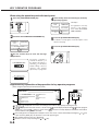
Improper installation may damage this product. Please note the following during initial installation and whenever the
machine is moved.
1. The machine should be installed near an accessible
power outlet for easy connection.
2. Be sure to connect the power cord only to a power
outlet that meets the specified voltage and current
requirements. Also make certain the outlet is properly
grounded.
● For the power supply requirements, see the name
plate of the main unit.
3.
Do not install your machine in areas that are:
damp, humid, or very dusty
● exposed to direct sunlight
● poorly ventilated
● subject to extreme temperature or humidity
changes, e.g., near an air conditioner or heater.
●
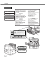
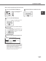
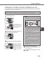
4. Be sure to allow the required space around the
machine for servicing and proper ventilation.
11-13/16" (30cm)
A small amount of ozone is produced within the copier
23-5/8"
(60cm)
23-5/8"
(60cm)
23-5/8" (60cm)
during operation. The emission level is insufficient to cause any health hazard.
NOTE:
The present recommended long term exposure limit for ozone is 0.1 ppm (0.2 mg/m3)
calculated as an 8 hr. time-weighted average concentration.
However, since the small amount that is emitted may have an objectionable odor, it is
advisable to place the copier in a ventilated area.
0-1
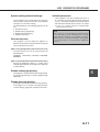
CAUTIONS
1. Do not touch the photoconductive drum. Scratches
or smudges on the drum will cause dirty printouts.
2. The fusing unit is extremely hot. Exercise care in
this area.
3. Do not look directly at the light source of a scanner
module. Doing so may damage your eyes.
4. Five installation adjusters are provided on a stand/
paper drawer which is provided as a peripheral unit.
When moving the machine with a stand/paper drawer,
be sure to raise the installation adjusters. After
moving the machine, lower the five installation
adjusters until they reach the floor.
Fusing unit
5. Do not make modifications to this machine. Doing
so may cause a fire or an electric shock.
6. When moving this machine, be sure to use two to
four persons. Since this machine is heavy, moving
it by yourself may cause an injury.
Adjuster
7. When connecting this machine to a computer, be
sure turn off this machine and the computer in
advance.
8. When opening or closing the covers or paper trays
for misfeed removal or loading paper, take care not
to get your fingers caught in the covers or trays.
Lock
Release
9. Do not print anything which is prohibited from printing
by law. The following items are normally prohibited
from printing by national law. Other items may be
prohibited by local law.
● Money ● Stamps ● Bonds ● Stocks
● Bank drafts ● Checks ● Passports
● Driver's licenses
"BATTERY DISPOSAL"
CONTAINS MANGANESE DIOXIDE LITHIUM BATTERY. MUST BE DISPOSED OF PROPERLY.
CONTACT YOUR SHARP DEALER OR SERVICER FOR INSTRUCTIONS.
This product utilizes tin-lead solder, and fluorescent lamp containing a small amount of mercury.
Disposal of these materials may be regulated due to environmental considerations.
For disposal or recycling information, please contact
your local authorities or the Electronics Industries
Alliance:www.eiae.org
0-2
CAUTIONS
Cautions on laser
Wave length
785 nm ± 15 nm
Pulse times
North America: (4.0 µs ± 4 ns)/7 mm
Europe: (5.4 µs ± 5.4 ns)/7 mm
Output power
0.25 mW - 0.50 mW
At the production line, the output power of the scanner unit is adjusted to 0.6
MILLIWATT PLUS 8 PCTS and is maintained constant by the operation of the
Automatic Power Control (APC).
Caution
This product contains a low power laser device. To ensure continued safety do not remove any cover or attempt
to gain access to the inside of the product. Refer all servicing to qualified personnel.
For North America:
SAFETY PRECAUTIONS
This Digital Equipment is rated Class 1 and complies with 21 CFR 1040.10 and 1040.11 of the
CDRH standards. This means that the equipment does not produce hazardous laser radiation. For
your safety, observe the precautions below.
●
Do not remove the cabinet, operation panel or any other covers.
●
The equipment's exterior covers contain several safety interlock switches. Do not bypass any
safety interlock by inserting wedges or other items into switch slots.
Caution
Use of controls or adjustments or performance of procedures other than those specified herein
may result in hazardous radiation exposure.
0-3
CAUTIONS
For Europe:
CLASS 1 LASER PRODUCT
LASER KLASSE 1
LUOKAN 1 LASERLAITE
KLASS 1 LASERAPPARAT
CAUTION
INVISIBLE LASER RADIATION
WHEN OPEN INTERLOCKS
DEFEATED. AVOID EXPOSURE
TO BEAM.
VORSICHT
UNSICHTBARE
LASERSTRAHLUNG WENN
ABDECKUNG GEÖFFNET UND
SICHERHEITSVERRIEGELUNG
ÜBERBRÜCKT. NICHT DEM
STRAHL AUSSETZEN.
ADVARSEL
USYNLIG LASERSTRÅLNING
VED ÅBNING, NÅR
SIKKERHEDSBRYDERE ER
UDE AF FUNKTION. UNDGÅ
UDSAETTELSE FOR
STRÅLNING.
CAUTION
VORSICHT
ADVARSEL
ADVERSEL
VARNING
VARO!
INVISIBLE LASER RADIATION WHEN OPEN AND INTERLOCKS DEFEATED.
AVOID EXPOSURE TO BEAM.
Laserstrahl
UNSICHTBARE LASERSTRAHLUNG WENN ABDECKUNG GEÖFFNET UND
SICHERHEITSVERRIEGELUNG ÜBERERÜCKT. NICHT DEM STRAHL AUSSETZEN.
USYNLIG LASERSTRÅLING VED ÅBNING, NÅR SIKKERHEDSAFBRYDERE ER
UDE AF FUNKTION. UNDGÅ UDSAETTELSE FOR STRÅLNING.
USYNLIG LASERSTRÅLING NÅR DEKSEL ÅPNES OG SIKKERHEDSLÅS BRYTES.
UNNGÅ EKSPONERING FOR STRÅLEN.
OSYNLIG LASERSTRÅLNING NÄR DENNA DEL ÄR ÖPPNAD OCH SPÄRRAR ÄR
URKOPPLADE. STRÅLEN ÄR FARLIG. BETRAKTA EJ STRÅLEN.
AVATTAESSA JA SUOJALUKITUS OHITETTAESSA OLET ALTTIINA NÄKYMÄTÖNTÄ
LASERSÄTEILYLLE. ÄLÄ KATSO SÄTEESEEN.
CLASS 1
LASER PRODUCT
LASER KLASSE 1
0-4
VAROITUS!
LAITTEEN KÄYTTÄMINEN
MUULLA KUIN TÄSSÄ
KÄYTTÖOHJEESSA
MAINITULLA TAVALLA SAATTAA
ALTISTAA KÄYTTÄJÄN
TURVALLISUUSLUOKAN 1
YLITTÄVÄLLE
NÄKYMÄTTÖMÄLLE
LASERSÄTEILYLLE.
VARNING
OM APPARATEN ANVÄNDS PÅ
ANNAT SÄTT ÄN I DENNA
BRUKSANVISNING
SPECIFICERATS, KAN
ANVÄNDAREN UTSÄTTAS FÖR
OSYNLIG LASERSTRÅLNING,
SOM ÖVERSKRIDER GRÄNSEN
FÖR LASERKLASS 1.
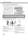
FACSIMILE FEATURE
When using this product as a facsimile by installing a facsimile expansion kit as a peripheral unit, refer to the following
items for proper use.
For the description of use of the facsimile feature, see the facsimile operation manual supplied with the facsimile
expansion kit.
Line connector
■ Line connection
TEL
For connection between this product and telephone line, be sure to
use the supplied connection cable. Connect the connecting cable so
that the terminal near the core is inserted to the line connector of the
facsimile expansion kit. Insert the other terminal (not the core side)
to the socket of the telephone line.
LINE
Core
■ Fax power switch
When using this product as a facsimile, keep always the fax power
switch on that is located on the facsimile expansion kit at the rear
side of this product. (Do not turn it off.) If the fax power switch is off,
the facsimile feature cannot be used.
TEL
LINE
ON
OFF
0-5
CONTENTS
Page
INSTALLATION REQUIREMENTS . . . . . . . . . . . . 0-1
CAUTIONS . . . . . . . . . . . . . . . . . . . . . . . . . . . . . . 0-2
CONTENTS . . . . . . . . . . . . . . . . . . . . . . . . . . . . . . 0-5
CHAPTER 1
BEFORE USING THE PRODUCT
INTRODUCTION . . . . . . . . . . . . . . . . . . . . . . . . . . . . .
MAIN FEATURES . . . . . . . . . . . . . . . . . . . . . . . . . . . .
PART NAMES AND FUNCTIONS . . . . . . . . . . . . . . . .
● Exterior* Interior . . . . . . . . . . . . . . . . . . . . . . . . . . .
●
Part names and functions of peripheral units . . . . .
Operation panel . . . . . . . . . . . . . . . . . . . . . . . . . . . .
●
Touch panel . . . . . . . . . . . . . . . . . . . . . . . . . . . . . . .
●
ADDING TONER . . . . . . . . . . . . . . . . . . . . . . . . . . . . .
LOADING PAPER . . . . . . . . . . . . . . . . . . . . . . . . . . . .
●
●
●
●
●
●
●
●
●
●
●
●
●
●
●
Loading paper in paper tray 1 . . . . . . . . . . . . . . . . .
Changing the paper size in paper tray 1 . . . . . . . . .
Paper available in paper trays . . . . . . . . . . . . . . . . .
Paper available in the bypass tray/multi
purpose drawer . . . . . . . . . . . . . . . . . . . . . . . . . . . .
Method of setting paper size and type . . . . . . . . . .
Setting from the operation panel of
a scanner module . . . . . . . . . . . . . . . . . . . . . . . . . .
Loading paper in the multi purpose drawer . . . . . . .
Changing paper size in the multi purpose
drawer . . . . . . . . . . . . . . . . . . . . . . . . . . . . . . . . . . .
Setting special paper in the multi purpose
drawer . . . . . . . . . . . . . . . . . . . . . . . . . . . . . . . . . . .
Specifications . . . . . . . . . . . . . . . . . . . . . . . . . . . . .
Loading paper in the stand/3 x 500 sheet
paper drawer . . . . . . . . . . . . . . . . . . . . . . . . . . . . . .
Changing paper size in the stand/3 x 500
sheet paper drawer . . . . . . . . . . . . . . . . . . . . . . . . .
Specifications . . . . . . . . . . . . . . . . . . . . . . . . . . . . .
Loading paper in the stand/MPD & 2000
sheet paper drawer . . . . . . . . . . . . . . . . . . . . . . . . .
Specifications . . . . . . . . . . . . . . . . . . . . . . . . . . . . .
CHAPTER 2
PRINTING FROM A COMPUTER
CONNECTING TO A COMPUTER . . . . . . . . . . . . . . .
SOFTWARE FOR WINDOWS . . . . . . . . . . . . . . . . . . .
INSTALLING PRINTER DRIVERS
AND PRINTER UTILITIES . . . . . . . . . . . . . . . . . . . . .
REMOVING PRINTER DRIVERS
AND PRINTER UTILITIES . . . . . . . . . . . . . . . . . . . . .
0-6
INSTALLING PRINTER DRIVERS USING
THE PLUG & PLAY FUNCTION OR
ADD PRINTER WIZARD . . . . . . . . . . . . . . . . . . . . . . .
● Before installation
SETTING THE PRINTER DRIVER . . . . . . . . . . . . . . .
Setting print conditions under Windows
(selecting and setting print conditions) . . . . . . . . . .
REMOTE OPERATION THROUGH NETWORK . . . . .
● Environment required for accessing
Web screen . . . . . . . . . . . . . . . . . . . . . . . . . . . . . . .
● Accessing Web screen and
displaying help . . . . . . . . . . . . . . . . . . . . . . . . . . . . .
● Items and outline of menu frame of
Web screen . . . . . . . . . . . . . . . . . . . . . . . . . . . . . . .
PRINT FUNCTIONS WHICH REQUIRING PRINT
START OPERATION FROM THE OPERATION
PANEL AND THEIR OPERATION METHOD . . . . . . . .
● Print functions selectable in the "JOB CONTROL"
dialog box and their operation . . . . . . . . . . . . . . . . .
● Printing method of hold job list . . . . . . . . . . . . . . . .
● Setting from the operation panel of
a scanner module . . . . . . . . . . . . . . . . . . . . . . . . . .
● Printer account control
●
CHAPTER 3
PRINTER BASIC SETTINGS
MAKING PRINTER CONFIGURATION
SETTING . . . . . . . . . . . . . . . . . . . . . . . . . . . . . . . . . . .
● Operation procedure common to all printer
configuration settings (items that can be set
from the operation panel) . . . . . . . . . . . . . . . . . . . . .
● Initial settings . . . . . . . . . . . . . . . . . . . . . . . . . . . . .
● PCL settings . . . . . . . . . . . . . . . . . . . . . . . . . . . . . .
● PS settings . . . . . . . . . . . . . . . . . . . . . . . . . . . . . . .
CUSTOM SETTINGS . . . . . . . . . . . . . . . . . . . . . . . . .
● Operation procedure common to all custom
settings (items that can be set from the
operation panel) . . . . . . . . . . . . . . . . . . . . . . . . . . . .
● Setting items . . . . . . . . . . . . . . . . . . . . . . . . . . . . . .
CONTENTS
CHAPTER 4
TROUBLESHOOTING AND
MAINTENANCE
CHAPTER 6
KEY OPERATOR PROGRAMS
MISFEED REMOVAL . . . . . . . . . . . . . . . . . . . . . . . . .
●
MACHINE TROUBLE? . . . . . . . . . . . . . . . . . . . . . . . .
USER MAINTENANCE . . . . . . . . . . . . . . . . . . . . . . . .
●
●
●
●
Cleaning the cabinet of the main unit . . . . . . . . . . .
Cleaning the paper feed section . . . . . . . . . . . . . . .
Cleaning the document glass and document
cover . . . . . . . . . . . . . . . . . . . . . . . . . . . . . . . . . . . .
CHAPTER 5
PERIPHERAL UNITS
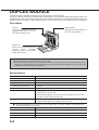
DUPLEX MODULE . . . . . . . . . . . . . . . . . . . . . . . . . . .
● Part names and functions . . . . . . . . . . . . . . . . . . . .
●
●
●
Specification . . . . . . . . . . . . . . . . . . . . . . . . . . . . . .
Loading paper in the bypass tray . . . . . . . . . . . . . .
Setting the printer driver for your purpose . . . . . . . .
KEY OPERATOR PROGRAMS . . . . . . . . . . . . . . . . . .
●
●
Key operator program list . . . . . . . . . . . . . . . . . . . .
Using the key operator programs . . . . . . . . . . . . . .
Details of classification of setting items
(hierarchical structure) and supplementary
explanation of key operation . . . . . . . . . . . . . . . . . .
Description of programs . . . . . . . . . . . . . . . . . . . . .
CHAPTER 7
APPENDIX
PRINTER SPECIFICATIONS . . . . . . . . . . . . . . . . . . .
INTERFACE SPECIFICATIONS . . . . . . . . . . . . . . . . .
LIST OF COMBINATION OF
PERIPHERAL UNITS . . . . . . . . . . . . . . . . . . . . . . . . .
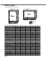
PRINT AREA . . . . . . . . . . . . . . . . . . . . . . . . . . . . . . . .
Setting the copier for your purpose . . . . . . . . . . . . .
● Troubleshooting? . . . . . . . . . . . . . . . . . . . . . . . . . . .
MAIL-BIN STACKER . . . . . . . . . . . . . . . . . . . . . . . . . .
●
●
Part names and functions . . . . . . . . . . . . . . . . . . . .
●
Specification . . . . . . . . . . . . . . . . . . . . . . . . . . . . . .
Outline of mail-bin stacker . . . . . . . . . . . . . . . . . . . .
●
Using the mail-bin stacker . . . . . . . . . . . . . . . . . . . .
● Misfeed removal in the mail-bin stacker . . . . . . . . .
FINISHER . . . . . . . . . . . . . . . . . . . . . . . . . . . . . . . . . .
● Part names and functions . . . . . . . . . . . . . . . . . . . .
●
Specification . . . . . . . . . . . . . . . . . . . . . . . . . . . . . .
● Outline of the finisher . . . . . . . . . . . . . . . . . . . . . . .
● Quick reference table for stapling . . . . . . . . . . . . . .
● Using the finisher functions . . . . . . . . . . . . . . . . . . .
● Staple jam removal and staple cartridge
replacement . . . . . . . . . . . . . . . . . . . . . . . . . . . . . . .
● Misfeed removal in the finisher . . . . . . . . . . . . . . . .
● Troubleshooting? . . . . . . . . . . . . . . . . . . . . . . . . . . .
SADDLE STITCH FINISHER . . . . . . . . . . . . . . . . . . .
● Part names and functions . . . . . . . . . . . . . . . . . . . .
● Specification . . . . . . . . . . . . . . . . . . . . . . . . . . . . . .
● Outline of the finisher . . . . . . . . . . . . . . . . . . . . . . .
● Quick reference table for stapling . . . . . . . . . . . . . .
● Printed image and saddle stitch . . . . . . . . . . . . . . .
● Using the finisher functions . . . . . . . . . . . . . . . . . . .
● Staple jam removal and staple cartridge
replacement . . . . . . . . . . . . . . . . . . . . . . . . . . . . . . .
● Misfeed removal in the finisher . . . . . . . . . . . . . . . .
● Troubleshooting? . . . . . . . . . . . . . . . . . . . . . . . . . . .
●
0-7
CHAPTER 1
BEFORE USING THE PRODUCT
This chapter describes basic information that should be read before using
this product. Be sure to read this chapter before using this product.
Page
INTRODUCTION ...................................................................................
MAIN FEATURES ..................................................................................
PART NAMES AND FUNCTIONS .........................................................
● Exterior ............................................................................................
● Interior .............................................................................................
● Part names and functions of peripheral units .................................
● Operation panel ..............................................................................
● Touch panel ....................................................................................
LOADING PAPER ..................................................................................
● Loading paper in paper tray 1 .........................................................
● Changing the paper size in paper tray 1 ........................................
● Paper available in paper trays ........................................................
● Paper available in the bypass tray/multi purpose drawer ..............
● Method of setting paper size and type ............................................
● Loading paper in the multi purpose drawer ....................................
● Specifications ..................................................................................
● Loading paper in the stand/3 x 500 sheet paper drawer ...............
● Specifications ..................................................................................
● Loading paper in the stand/MPD & 2000 sheet paper drawer .......
● Specifications ..................................................................................
ADDING TONER ...................................................................................
STORAGE OF SUPPLIES .....................................................................
1-2
1-5
1-6
1-6
1-7
1-8
1-11
1-15
1-18
1-18
1-18
1-19
1-19
1-20
1-22
1-22
1-23
1-23
1-24
1-24
1-25
1-25
1-1
INTRODUCTION
Read this operation manual carefully to use this product properly. Be sure to read “INSTALLATION REQUIREMENTS”
and “CAUTIONS” before using this product.
Be sure to keep this operation manual handy to refer to it any time.
This product is a multi-function printer that can be used as a local printer and a network printer as well as a copier,
network scanner, and a facsimile by installing various types of peripheral units (optional).
This operation manual describes the basic use of the product as a printer and also describes operation items common
to the printer and other features such as loading paper, misfeed removal, and user maintenance.
If you extend this product to use the copier feature, network scanner feature, facsimile feature or network printer
feature, relevant operation manuals are supplied. Read the respective manuals for using the features.
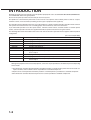
The following table shows the model names of the main units to which this operation manual applies and their product
configuration.
(As of end of April 2001)
Model name
AR-P350
AR-P450
AR-M350
AR-M450
DM-3500
DM-3501
DM-3551
DM-4500
DM-4501
DM-4551
Product configuration
35 pages/minute printer
45 pages/minute printer
35 pages/minute printer (with a multi-function controller board)*1
45 pages/minute printer (with a multi-function controller board)*1
35 pages/minute printer
35 pages/minute network printer (with a print server card)*2
35 pages/minute network printer (with a multi-function controller board and a print
server card)*3
45 pages/minute printer
45 pages/minute network printer (with a print server card)*2
45 pages/minute network printer (with a multi-function controller board and a print
server card)*3
Although the peripheral units are basically optional, some units may be provided as standard components depending
on the model.
*1 A multi-function controller board required to extend the product to a multi-function printer that can be used as a
copier, facsimile, and a network scanner is provided as a standard component.
*2 A print server card required to extend the product to a network printer is provided as a standard component.
*3 A multi-function controller board and a print server card are provided as standard components.
1-2
INTRODUCTION
Abbreviated names of peripheral units
The following unit is written with an abbreviated name without some exceptions to simplify the description in this
manual.
“B/W scanner module/DSPF”
The unit is written as “scanner module”.
NOTES
● The scanner unit is a unit for scanning originals (automatic document feeder) when using the copier feature and
facsimile feature. In the touch panel messages in the scanner module, the “scanner module” is displayed as
“document feeder”.
● To use a scanned image as image data on a computer, a network scanner expansion kit (peripheral unit) is needed
in addition to the network printer environment.
“Duplex module”
This is a unit that allows printing onto two sides of paper. A single “duplex module” and a “duplex module/bypass tray”
are supplied. In this manual, both units are written as “duplex module” with some exception and description is made
mainly for the “duplex module/bypass tray”. The description for the bypass tray, therefore, is made only for the “duplex
module/bypass tray”. In the pages of “duplex module”, illustrations with an output tray are used. This output tray is
optional for both the duplex modules. (not included in the duplex modules)
1-3
1
INTRODUCTION
Manual paper feeding
✱4
✱1
Two-sided print
✱4
✱1
✱3
✱1
✱4
✱3
✱2
✱2
Offset stack of printed sheets
✱5
✱1
Stapling of printed sheets
✱5
✱1
Center stapling of printed sheets
✱3
Punching of printed sheets
✱3
Mail bin stack of printed sheets
✱2
✱2
✱2
✱2
✱2
✱2
✱2
✱5
✱2
Printer feature
Network printer
Job retention function
✱3
Pamphlet print
✱1
✱2
PostScript3 compatibility
Copier feature
Peripheral units required at
the minimum for using the
copier feature
✱1
✱1
Pamphlet copy
✱6
Facsimile feature
Peripheral units required at
the minimum for using the
facsimile feature
✱1
✱1
Memory for original images of
xx sheets or more
✱7
Telephone call
Network scanner feature
Peripheral units required at the
minimum for using the network
scanner feature
1-4
✱1
✱1
Hard disk drive
Power supply unit
Additional fax memory (8 MB)
Facsimile expansion kit
Network scanner expansion kit
PS3 expansion kit
Print server card
Multi-function controller board
Punch module
Upper exit tray extension
Exit tray
Mail-bin stacker
Finisher
Saddle stitch finisher
Duplex module
Duplex module/bypass tray
✱3
Print onto special paper
Touch panel operation
Stand/MPD & 2000 sheet paper drawer
Stand/3 x 500 sheet paper drawer
Multi purpose drawer
Scanner rack
Common to all features
B/W scanner module/DSPF
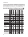
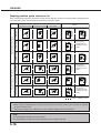
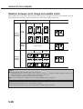
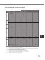
The following table shows the relation between the various functions described in this manual, copier operation manual,
facsimile operation manual, and network scanner operation manual and the required peripheral units. In each operation
manual, the optional peripheral units that are required for using each function is not particularly described. Refer to this
table as needed.
= Must be installed *1 = Any of the units must be installed. *2 = Must be installed together with or *1. *3
= Any of these units must be installed together with or *1. *4 = Required when a stand/3 x 500 sheet paper
drawer or a stand/MPD & 2000 sheet paper drawer is installed. *5 = Any of these units must be installed together
with or *1 but the multi purpose drawer is excluded when a saddle stitch finisher is installed. *6 = Any of these
units must be installed in addition to the peripheral units required at the minimum for using the copier feature. *7 =
Must be installed in addition to the peripheral units required at the minimum for using the facsimile feature.
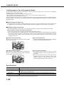
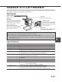
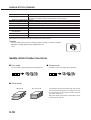
MAIN FEATURES
Multi-function printer allowing extension of functions based on the purpose
This product is a multi-function printer that can be used as a local printer and a network printer as well as a copier,
a network scanner, and a facsimile by combining peripheral units. Various optional units for improving productivity
such as duplex modules for two-sided printing, additional paper feed units for large capacity paper stock, and paper
output units for sorting printed sheets are provided as peripheral units.
600 dpi high resolution printing
High definition and high quality printing with 600 dpi resolution can be performed. Also high image quality equivalent
to 1200 dpi can be output by using the soothing function.
Monochrome high-speed printing
High-speed printing of 35 pages/minute or 45 pages/minute can be performed for 8-1/2" x 11" or A4 size.
PostScript compatible
Installation of a PS3 expansion kit gives PostScript compatibility (PostScript level 3).
ENERGY STAR
As an ENERGY STAR® Partner, SHARP has determined that this product meets the ENERGY STAR® guidelines
for energy efficiency.
Energy saving feature
This product has the following two power save modes that conform the Energy
Star guidelines to conserve natural resources and to help reduce environmental
pollution.
Preheat mode
The machine will enter the preheat mode once the time set with a key operator program has elapsed without
any operation. In this mode, the fuser is maintained at a lower heat level thereby saving power.
Auto power shut-off mode
The machine will enter the auto power shut-off mode once the time set with a key operator program has
elapsed without any operation. In this mode, power to the display and the fuser is turned off and only the
lowest power is consumed. In this mode, power can be saved more than the preheat mode but more time is
needed to return to the operating state. This mode can be disabled using a key operator program.
If this product is used as a printer, when print data is received in the preheat mode or the auto power shut-off
mode, the mode will be automatically canceled and printing will start after the fuser temperature is restored to
the normal operating level.
If this product is used as a multi-function machine, the mode will be automatically canceled when print data or
facsimile data is received or when any key operation on the operation panel or original setting operation for
copying or facsimile transmission is performed.
1-5
1
PART NAMES AND FUNCTIONS
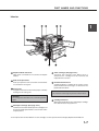
Exterior
Bypass tray (part of duplex module/bypass tray)*1
Front cover
Open to add toner and remove misfeeds.
Exit tray*1
Duplex module*1
Module for two-sided printing
Main switch (See page xxxx.)
Press to turn power on and off.
Paper tray 1
Upper paper output area
Finished sheets are deposited here.
Upper exit tray extension*1
Extension table for preventing dropping of large paper
such as 11" x 17" and 8-1/2" x 14" (A3 and A4).
Operation panel (See page xxxx.)
*1
Stand/3 x 500 sheet paper drawer*1 (See page
xxxx.)
Stand/MPD & 2000 sheet paper drawer*1
(See page xxxx.)
Multi purpose drawer*1 (See page xxxx.)
,
,
,
,
,
, and
are peripheral units. For description of these units, see page xx. The configuration
of peripheral units varies with the main unit model.
1-6
PART NAMES AND FUNCTIONS
Interior
1
Duplex module side cover
Open when a misfeed has occurred in the duplex
module.
Side cover open knob
Push up to open the side cover when a misfeed has
occurred in the fusing unit.
Fusing unit
Image that has been transferred on paper is fixed by
heating it in the fusing unit.
CAUTION
The fusing unit is hot. Take care in removing misfed
paper.
Toner cartridge* (See page xxxx.)
Container that contains toner. When toner is
exhausted, the cartridge must be removed and
replaced with a new one.
Photoconductive drum
A photoconductor is applied to the surface of the
photoconductive drum. Images are formed on the
photoconductive drum.
NOTE
Do not touch or damage the photoconductive drum.
Cartridge lock lever
When replacing the drum, toner or developer cartridge,
turn down this lever and pull it out.
Developer cartridge* (See page xxxx.)
Container that contains developer. The cartridge must
be removed and replaced with a new one at the time
of replacement.
*2 For replacement and installation of each cartridge, see the separate manual “Supply Replacement Method.”
1-7
PART NAMES AND FUNCTIONS
Part names and functions of peripheral units
1-8
PART NAMES AND FUNCTIONS
B/W scanner module/DSPF
This unit is a monochrome scanner that allows
automatic feeding of sheet originals and continuous
scanning. The B/W scanner module/DSPF (Dual
Single Pass Feeder) can scan two-sided sheet
originals and can scan both sides at a time. Also a
flat bed type document glass is provided in this unit
for scanning an original that cannot be fed such as a
book and thick original.
Upper exit tray extension
Mount this unit to the upper paper exit tray. This unit
is needed for output of 11" x 17" (A3) paper.
Finisher
Sorted output sheets or grouped output sheets by
page are offset stacked so that each set can be
taken out easily.
Also sorted output sheets can be stapled.
Mail-bin stacker
This unit is an output sheet sorting unit that contains
seven bins. When printed sheets are output in the
printer mode, a bin to which printed sheets are to be
deposited can be specified in the printer driver. The
bins can be classified by persons or by sections
depending on users so that the users deliver their
printed sheets to their specified bin. Sorted output
separated from the other users, therefore, can be
performed.
Output sheets in the copy and fax modes are
deposited in the top tray other than these seven bins.
Stand/MPD & 2000 sheet paper drawer
This is a paper feed unit that contains two paper
trays. The upper tray is equivalent to the multi purpose
drawer. The lower tray holds approximately 2000
sheets of 20 lbs. (80 g/m2) paper.
Multi purpose drawer
Holds paper. Up to 500 sheets of 20 lbs. (80 g/m2)
paper can be loaded. Also special papers such as
envelopes (standard sizes only) and Japanese
postcard can be set.
Stand/3 x 500 sheet paper drawer
This is a paper feed unit that contains three paper
trays. The upper tray is equivalent to the multi purpose
drawer. Each of the lower two trays holds up to 500
sheets of 20 lbs. (80 g/m2) paper.
Saddle stitch finisher
Sorted output sheets or grouped output sheets by
page are offset stacked so that each set can be
taken out easily. Also sorted output sheets can be
stapled at the edge or at the center for center-stapled
binding.
In addition, if a punch module is installed as a
peripheral unit, punch holes can be made in the
output sheets for filing.
Duplex module
Unit for automatic two-sided printing.
Duplex module/bypass tray
This module is equipped with a unit for automatic
two-sided printing and a bypass tray manual paper
feeding.
Exit tray
Mounted to the paper output port of a duplex module
or a duplex module/bypass tray.
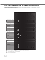
For installation of a peripheral unit, installation of some other peripheral units may be needed together and installation
of some peripheral units may not be possible together. See page xx, “COMBINATION OF PERIPHERAL UNITS.”
Peripheral units are basically optional but some units may be provided as standard units depending on the main unit
model.
1-9
1
PART NAMES AND FUNCTIONS
■ Other peripheral units
●
Scanner rack
Rack required for installing a scanner module. The
height is fixed.
●
Power supply unit
For installation of some peripheral units, this unit is
required for supplying power to each unit.
●
Print server card
NIC (network interface card) for using the printer as
a network printer.
●
●
Multi-function controller board
Printer controller required for using the copier,
facsimile, and network scanner features.
●
Hard disk drive
Extends the image storing capacity for the printer
and copier features (not for the facsimile feature).
Also this unit is required for using the job retention
function (see page xxxx) with which print data
received for the printer feature is held temporarily
instead of immediate output.
●
Facsimile expansion kit
Kit required for using the facsimile feature.
●
Additional fax memory (8 MB)
●
Network scanner expansion kit
Kit required for using the network scanner feature.
PS3 expansion kit
Kit required for using the printer as a PostScript
compatible printer. (for PostScript level 3)
For installation of a peripheral unit, installation of some other peripheral units may be needed together and installation
of some peripheral units may not be possible together. See page xx, “COMBINATION OF PERIPHERAL UNITS.”
Peripheral units are basically optional but some units may be provided as standard units depending on the main unit
model.
1-10
PART NAMES AND FUNCTIONS
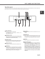
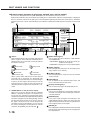
Operation panel
The display and indicators in the operation panel located on the front of the machine indicate the current status of the
printer. Also the keys on the operation panel allow settings required for printing.
1
Message display
Displays the printer current state.
[i] displayed in messages indicates the
[INFORMATIONS] key.
[ERROR] indicator
Lights up when paper or toner must be added or when
a misfeed has occurred. Blinks when an abnormal
condition has occurred in this machine.
[DATA] indicator
Lights up or blinks when print data is being received.
Also lights up when printing is being performed.
[READY] indicator
Printing can be executed when this indicator is lit.
[MENU] key
Press to select a menu group such as printer
configuration menu (page xxx), custom settings, and
execution of printing held by the retention function
(page xxx). Press also to return to the menu screen
from the setting screen of each menu group.
[ / ] keys
Press to select each menu or function or to set a
number.
[BACK/C] key
Use this key to return to the previous screen in each
menu selection, to cancel and delete the current job
or to delete a reserved job that has been selected.
[OK] key
Press to register the selected menu or function.
[INFORMATION] key
When [ i ] is displayed with a message indicating a
paper misfeed, requesting toner addition, etc., the
relevant operation procedure can be displayed by
pressing the [INFORMATION] key. If the
[INFORMATION] key or the [BACK/C] key is pressed
while the operation procedure is displayed, the
information mode will be canceled. If you press and
hold down this key while printing is being performed
or in the standby, the total number of printed pages
and quantity of toner remaining (as a percent) will be
displayed.
1-11
PART NAMES AND FUNCTIONS
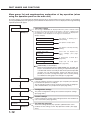
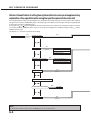
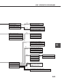
Menu group list and supplementary explanation of key operation (when
using the operation panel on the main unit)
The menu groups are classified into the following five groups as shown below. These menu groups are selected by
pressing the [MENU] key. If the [OK] key is pressed when the desired menu screen is displayed, a message indicating
required operation will appear.
Job status screen
READY.
[MENU] key
The message "WARMING UP" displayed when the power is turned on and
the list of the current job and the reserved jobs or the list of completed jobs
are displayed on the job status screen. Various messages are displayed on
the job status screen. Examples of messages are shown below.
(Display example)
WARMING UP.
The printer is warming up to
allow printing.
READY.
The printer is ready to print.
FROM TRAY #
The printer is currently executing
printing.
CHANGE THE TONER
CARTRIDGE.
Toner runs out. Replace the
toner cartridge. (See page
xxxx.)
PAPER JAM.
A misfeed has occurred. (See
page xxxx.)
ADD PAPER.
Paper runs out. Load paper.
(See page xxxx.)
[ADD PAPER] of status display
When the status display shows [ADD PAPER], the specified size
paper is not loaded. In this case, printing is suspended until paper
is loaded and another reserved job data will be printed if possible.
(If paper runs out during printing, another job data will not be
printed.) If you wish to change the paper size to resume printing,
see "Method of setting paper size and type" on page xxxx.
PRINT HOLD
Print hold
[MENU] key
If the job retention function is used from your computer, print data will
be stored in the printer as a hold job.
The job retention function can be used only if the printer is equipped
with a hard disk drive as a peripheral unit. (See page xxxx.)
CONDITION SETTINGS
Configuration settings
[MENU] key
CUSTOM SETTINGS
[MENU] key
KEY OPERATOR
PROGRAMS
Custom settings
Custom settings are used to make settings based on the conditions of
use of customers. (See page xxxx.)
Key operator programs
[MENU] key
1-12
The printer configuration settings are used for basic printer settings.
(See page xxxx.)
These are settings used by key operators (administrators of this
product). For the setting, see the "Key Operator's Guide". (See page
xxxx.)
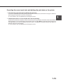
Canceling the current print job and deleting the print data on the printer
●
To cancel the current print job and delete the print data:
If you press the [BACK/C] key during printing, printing will be canceled and a confirmation message for deletion of
data will appear. To delete the data, press the [OK] key.
To cancel deletion, press the [BACK/C] key. Printing will resume.
●
To delete print data of a reserved job (that waits for printing):
Print data transmitted from computers will be stored in this printer (up to 99 jobs) and will be output sequentially. To
delete print data of a reserved job before starting printing, press the [ ] or [ ] key to display the desired data in the
message display. If you press the [BACK/C] key at this time, a confirmation message for deletion will appear. To
delete the data, press the [OK] key.
To cancel deletion, press the [BACK/C] key. Printing will resume.
1-13
1
PART NAMES AND FUNCTIONS
When the printer is equipped with a scanner module as a peripheral unit, use the operation panel with a touch panel on
the scanner module.
[Touch panel]
Messages and keys are displayed here. Operation
can be performed by touching keys displayed here.
The display is switched depending on each function
in the print, copy, network scan, and fax modes. For
details, see page xxxx.
[Mode select] keys and indicators
Use to switch the display mode of the touch panel.
[PRINT] key/READY indicator/DATA indicator
Press to switch the display to the print mode. (See
next page.)
● READY indicator
Printing can be performed when this indicator is
lit.
● DATA indicator
Lights up or blinks when print data is being
received. Also lights up when printing is being
performed.
[IMAGE SEND] key/LINE indicator/DATA indicator
Press to switch the display to the network scan/fax
mode. (See page xxxx of the facsimile operation
manual.)
[COPY] key
Press to switch the display to the copy mode. (See
page xxxx.)
1-14
[JOB STATUS] key
Press to display the current job status. (See page
xxxx.)
[CUSTOM SETTINGS] key
Use to adjust the contrast of the touch panel or to
set key operator programs.
[Numeric] keys
Use to enter a number in various settings.
[ ] key ([ACC.#-C] key) (See page xxxx.)
Use when using the copier feature and the facsimile
feature.
[#/P] key (See page xxxx.)
Use when using the copier feature and the facsimile
feature.
[C] key
Use when using the copier feature and the facsimile
feature.
[Start] key (See page xxxx.)
Use when using the copier feature and the facsimile
feature.
[CA] key
Use when using the copier feature and the facsimile
feature.
PART NAMES AND FUNCTIONS
Touch panel
Print mode screen
This screen is displayed when the print mode is selected.
(The display varies with the mode. For the display in other modes, see respective operation manuals.)
1
SELECT JOB.
PRINT HOLD JOB LIST
Sharp 005
Microsoft Word - Test001
Sharp 006
1/1
EXCEL1
CONDITION
SETTINGS
Message display
Messages are displayed here.
Job status screen (See next page.)
Print hold job list
If the job retention function (see page xxxx) is used,
the list of stored print data is displayed here (up to
100 jobs). The job retention function can be used
only if the printer is equipped with a hard disk drive
as a peripheral unit.
[Display switching] keys
Use to switch the page of the print hold job list. If the
list is not contained in a page, succeeding pages
are prepared. Use these keys to switch the display.
[CUSTOM SETTINGS] key
Use to switch the display to the printer configuration
menu (see page xxxx).
1-15
PART NAMES AND FUNCTIONS
Job status screen (common to print, copy, network scan, and fax modes)
This screen is displayed when the [JOB STATUS] key on the operation panel is pressed.
A job list which indicates the current job and reserved jobs or a job list which indicates completed jobs is displayed.
You can check the contents of the jobs, give a reserved job the highest print priority in the print queue, and delete
a job that you wish to cancel. (The following screen indicates a job list which indicates the current job and reserved
jobs.)
JOB QUEUE
COPY
SETS / PROGRESS
003 / 000
JOB QUEUE
1/1
COMPLETE
SHANE COFFEY
003 / 000
WAITING
054234
010 / 000
WAITING
PRIORITY
CLIFF QUIROGA
003 / 000
WAITING
STOP/DELETE
E-MAIL JOB
FAX JOB
PRINT JOB
Job list
A job list which indicates the current job and reserved
jobs or a job list which indicates completed jobs is
displayed. The icons at the top of each job indicate
the mode of each job.
Print mode
Copy mode
Network scan mode
Fax mode
(transmission job)
Fax mode
(reception job)
When a job list which indicates the current job and
reserved jobs is displayed, the displayed jobs
themselves are operation keys. To cancel printing or
to give a job the highest print priority, touch the
relevant job key to select the job and execute the
desired operation using the keys described in 7, 8,
and 9.
*1: “PAPER EMPTY” in the job status display
When the job status display indicates “PAPER
EMPTY”, specified size paper is not loaded in any
tray. In this case, printing is suspended until paper
is loaded and another reserved job data will be printed
if possible. (If paper runs out during printing, another
job data will not be printed.) If you wish to change
the paper size because you cannot prepare the
specified size paper immediately, you can change
the size by touching the current job key to select it
and touch the [DETAIL] key described in .
1-16
STATUS
COPYING
DETAIL
[Mode switching] key
Use to switch the job list between “JOB QUEUE”
and “COMPLETE”.
“JOB QUEUE”: Displays the list of the current job
and the reserved jobs.
“COMPLETE”: Displays the list of completed jobs.
[PRINT JOB] key
Use to display the print job list for all modes (print,
copy, network scan, and fax).
[E-MAIL JOB] key
Use to display the list of jobs that use the network
scanner feature.
[FAX JOB] key
Use to display the fax communication status and
the reserved transmission job status.
[Display switching] keys
Use to switch the page of the displayed job list.
[STOP/DELETE] key
Use to cancel or delete the current job or delete the
selected reserved job. Reserved fax jobs, however,
cannot be deleted.
[PRIORITY] key
If you select a job among the reserved jobs in the
“JOB QUEUE” job list to which you wish to give the
highest priority and touch this key, the job will move
to the highest priority reserved job.
[DETAIL] ke
Use to display the detailed information of the selected
job. The paper size for printing can be changed from
the specified size.
PART NAMES AND FUNCTIONS
Using the touch panel
■ How to use the touch panel
■ Selection of function
[Example 1]
[Example 1]
JOB QUEUE
COPY
SETS / PR
003 / 00
SHANE COFFEY
003 / 00
054234
010 / 00
CLIFF QUIROGA Beep
003 / 00
tone
You can easily set or
cancel a function by
touching a key on the
display with a finger. The
touch panel operation can
be confirmed with a beep
tone and highlighted
display.
1
[Example 2]
1/13
COMPLETE
If any key is disabled on
each screen, the key is
displayed gray. If you
press the key, two short
beeps will be sounded.
If any key is highlighted in the initial setting of each
setting screen, the function will be registered when
you touch the [OK] key without additional operation.
[Example 2]
The beep tone of key touch can be disabled by a
key operator program. (See page xxxx of the Key
Operator’s guide.)
The touch panel (display) illustrated in this operation
panel is a conceptual illustration.
DUAL PAGE
COPY
MULTI SHOT
When using the copier
feature or the facsimile
feature, the functions
shown below which can
be set by only touching
the relevant key in the
special feature screen
can be canceled by
touching the key again
(canceling highlighted
display).
Copier feature
Facsimile feature
Dual page copy
B/W reverse
Rotation copying in
two-sided copying
Centering
Polling
Own number print
Page cutoff
[Example 3]
DUAL PAGE
COPY
MULTI SHOT
DUAL PAGE
COPY
MULTI SHOT
When using the copier
feature or the facsimile
feature, if a special
function is set, the
corresponding function
icon will appear. If this
icon is touched, the
setting screen of the
function (or a menu
screen) will appear,
allowing the settings to be
checked or adjusted and
the function to be
canceled easily.
1-17
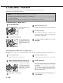
LOADING PAPER
When paper runs out during printing, a message indicating that paper runs out will appear.
Follow the procedure below to load paper.
NOTES
Do not use curled or folded paper. Doing so may cause a misfeed.
● Use SHARP standard paper for paper tray 1. (See page xxxx.)
● When you change the paper type in paper tray 1, set the paper type referring to “Method of setting paper size
and type” (page xxxx).
● Do not place a heavy object or press down hard on a tray when the tray is pulled out.
●
Loading paper in paper tray 1
1
Pull out paper tray 1.
Gently pull the tray out
until it stops.
2
3
Gently push paper tray 1.
Push the tray firmly all the way into the machine.
4
Set the paper type.
5
Loading of paper in paper tray 1 is now
complete.
If you change the paper type, be sure to set the
paper type referring to “Method of setting paper
size and type” (page xxxx).
Load paper into the tray.
Do not load paper above
the maximum height line
(approximately 500
sheets of 20 lbs. (80 g/m2)
paper).
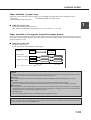
Changing the paper size in paper tray 1
For paper tray 1, 8-1/2" x 11", A4 or B5 size paper can be set. Use the following procedure to change the size as
needed.
1
2
Pull out paper tray 1.
If paper remains in the tray, remove it.
Adjust the guide plates A and B in the
tray to the length and width of the paper.
4
Gently push paper tray 1.
5
Set the paper size.
The guide plates A and B
are slidable. Adjust them
to the paper size to be
loaded while squeezing
their lock levers.
3
Load paper into the tray.
1-18
6
Push the tray firmly all the way into the machine.
Be sure to set the paper size and paper type
referring to “Method of setting paper size and type”
(page xxxx).
If this operation is not performed after the paper
size has been changed, printing will be made to
paper of a size other than the specified size and a
paper misfeed may occur.
Changing of paper size in paper tray 1 is
now complete.
LOADING PAPER
Paper available in paper trays
Paper that can be used varies with the paper trays. Use SHARP standard paper in the following paper trays.
● Paper tray 1
● Stand/MPD & 2000 sheet paper drawer
● Stand/3 x 500 sheet paper drawer
1
■ Paper that can be used
● SHARP standard paper (See page xx.)
Use SHARP standard paper ranging from 5-1/2" x 8-1/2" (A5) to 11" x 17" (A3).
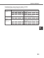
Paper available in the bypass tray/multi purpose drawer
Since the paper feeding method in the bypass tray and the multi purpose drawer varies with the paper type, be sure to
feed paper using the method adequate to the paper type. If the paper feeding method is not proper, a paper misfeed or
oblique feeding may occur.
■ Paper that can be used
● SHARP standard paper
● Ordinary paper other than SHARP standard paper
Paper size
5-1/2" x 8-1/2" or
A5 (105 x 148 mm)
11" x 17" or A3
(297 x 420 mm)
Paper weight:
Continuous feeding 15 lbs.(52 g/m 2 )
Single sheet feeding 15 lbs.(52 g/m 2 )
*1
28 lbs.(105 g/m 2 )
54 lbs.(205 g/m 2)
28 lbs.(105 g/m 2 )
28 lbs.(105 g/m 2)
g/m 2 ..... Weight of a sheet of paper of 1 m 2
NOTES
● Do not use paper that is not included in the range described above. Improper fusing (fusing strength of toner to
paper is weak and toner comes off if rubbed) and misfeeds may occur.
■ Envelope
● Standard envelope sizes are only the following four: Monarch (MON), Commercial-10 (C10), DL, and C5.
■ Postcard
● Double postcards can be used unless they have a fold. (Folded postcards cannot be used.)
● Do not use unofficial postcards or picture postcards. They may cause misfeeds or smudges on printouts.
■ Special paper
● For transparency film, letterhead paper, recycled paper, pre-printed paper, pre-punched paper, colored paper,
heavy paper, labels, and postcards, use SHARP recommended paper. Using paper that is not recommended by
SHARP may cause misfeeds and smudges on printouts.
● Notebook paper
Do not use paper that has been cut manually. Paper misfeeds may occur.
NOTE
There are various types of special paper on the market and some of them cannot be used in this product. When
using such paper, contact your SHARP dealer.
1-19
LOADING PAPER
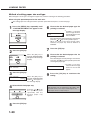
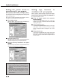
Method of setting paper size and type
When the paper size or type is changed in a paper tray, set them referring to the following procedure.
When using the operation panel on the main unit:
For setting paper size and type from the operation panel with touch panel, see the next page.
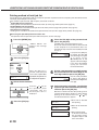
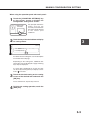
1
Press the [MENU] key repeatedly until
“CUSTOM SETTINGS” will appear in the
message display.
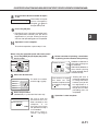
6
Ensure that the desired paper type for
printing is selected.
●
LETTER
PLAIN
If the desired paper type for printing is not selected,
press the or key on the operation panel.
When you wish to print onto special paper,
however, the paper tray must be TRAY 2 or
BYPASS.
CUSTOM SETTINGS
2
Press the [OK] key.
When the [OK] key is
pressed,“TRAY SETTING”
will appear in the message
display.
7
8
Press the [OK] key.
Ensure that the desired paper size for
printing is selected.
If the desired paper size for printing is not selected,
press the or key on the operation panel after
checking the paper type.
●
LETTER
OK?
TRAY SETTING
3
Press the [OK] key.
TRAY SETTING
TRAY1
4
When the [OK] key is
pressed,“TRAY SETTING
TRAY1 ” will appear in
the message display.
Select the desired paper tray.
Press the or key on
the operation panel
repeatedly until the
desired paper tray
appears.
5
Press the [OK] key.
1-20
If TRAY 1 is selected,
the message shown to
the left will appear in the
initial condition.
9
If TRAY 1 has been
selected, the message
shown to the left will
appear.
Press the [OK] key to terminate the
setting.
NOTE
Special paper such as transparency film, labels, and
postcards can be set for tray 2 and the bypass tray.
Envelopes can be set only for tray 2.
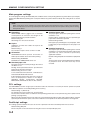
LOADING PAPER
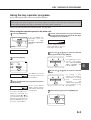
When using the operation panel with touch panel:
1
Press the [CUSTOM SETTINGS] key.
The custom setting menu
screen will appear.
5
Touch the [OK] key to complete the setting.
TOTAL COUNT
1
TRAY SETTINGS
2
Press the [TRAY SETTINGS] key.
TOTAL COUNT
The paper tray selection
screen will appear.
TRAY SETTINGS
3
Select the paper tray for which setting is
to be made.
TYPE / SIZE
TRAY 1
PLAIN / 81/2X11
TRAY 2
PLAIN / AUTO-INCH
TRAY 3
RECYCLED / AUTO-INCH
4
●
If the desired tray is not
displayed, touch the [ ]
or [ ] key to switch the
screen.
Select the paper type and the paper size.
If TRAY 1 has been selected in step 3:
CUSTOM SETTINGS
TRAY 1 TYPE/SIZE SETTING
OK
TYPE
SIZE
PLAIN
LETTER HEAD
8 X11
PRE-PRINTED
PRE-PUNCHED
B5
RECYCLED
COLOR
A4
The paper type and paper size with highlighted
display are selected. If the desired paper type and
paper size are not selected, select the desired type
and size by touching the relevant keys.
Special papers such as transparency film and
labels can be set for tray 2 and the bypass tray.
Envelopes can be set only for tray 2.
1-21
LOADING PAPER
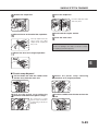
Loading paper in the multi purpose drawer
The method of loading paper for the multi purpose drawer is the same for paper tray 1 in the main unit. Load paper
referring to steps 1 to 5 on page xxxx.
The following items, however, are different from paper tray 1.
Ordinary paper of standard sizes from 11" x 17" to 5-1/2" x 8-1/2"R (A3 to A5R) can be set.
Also certain types of special paper can be set.
For special papers that can be set, see “Paper available in the bypass tray/multi purpose drawer” on page xxxx. When
setting envelopes or postcards in the multi purpose drawer, read thoroughly the description of “Setting envelopes or
postcards” below.
●
●
■ How to change the paper size
If the paper size or paper type is changed when paper is set in the tray, the tray settings in the custom settings must
be changed. Be sure to change the setting referring to “Method of setting paper size and type” on page xxxx.
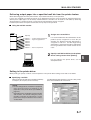
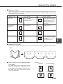
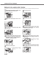
■ Setting envelopes or postcards
When setting envelopes or postcards in the multi purpose drawer, set them in the orientation shown below.
Notes common to setting of envelopes and postcards
● Do not print onto two sides. A paper misfeed or improper printing may occur.
● Be sure to write addresses after printing. Do not use envelopes or postcards on which printing has been performed
with a thermal transfer printer or an ink jet printer. Paper on which printing has been performed with a thermal
transfer printer with a ribbon cassette, particularly, may cause printed characters to come off or may cause
smudges on printouts.
Example of setting postcards
Be sure to set the postcards face down and the upper
part located in the left.
Note on setting postcards
● Smooth out curled postcards before printing. Crumpling,
misfeeds or improper printing may occur.
Example of setting envelopes
For envelopes, only the address side can be printed on.
Be sure to set envelopes with the address side down
and the upper part located in the left.
Notes on setting of envelopes
● For envelope sizes that can be used, see “Paper
available in the bypass tray/multi purpose drawer” on
page xxxx.
● Do not use envelopes that have metal clasps, plastic
snappers, string closures, windows, linings, selfadhesive patches or synthetic materials. A paper
misfeed, improper fixing or failure may occur.
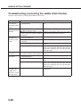
Specifications
Name
Paper size
Paper capacity
Dimensions
Weight
Multi purpose drawer
Max. 11" x 17" (A3), min. 5-1/2" x 8-1/2"R (A5R)
500 sheets (20 lbs. (80 g/m2)) of paper, 100 envelopes, 100 postcards,
100 sheets of transparency film
23-1/32" (W) x 20-7/8" (D) x 4-1/2" (H) (585 mm (W) x 530 mm (D) x 114 mm (H))
Approximately xxxx kg
Specifications are subject to change for improvement without notice.
1-22
LOADING PAPER
Loading paper in the stand/3 x 500 sheet paper drawer
Upper paper tray:
The upper paper tray is equivalent to the multi purpose drawer. The method of loading paper and the paper that can be
used are the same as for the multi purpose drawer. Read the description of the multi purpose drawer (see page xxxx).
Middle and lower paper trays:
Up to 500 sheets of 11" x 17", 8-1/2" x 14", 8-1/2" x 11", 8-1/2" x 11"R, 7-1/4" x 10-1/2", A3, B4, A4, A4R, B5, and B5R
paper (20 lbs. (80 g/m2)) can be loaded in these trays. The method of loading paper is the same as for paper tray 1 in
the main unit. See the description (page xxxx).
NOTE
If the paper size or paper type is changed when paper is set in a tray of the stand/3 x 500 sheet paper drawer, the tray
settings in the custom settings must be changed. Be sure to change the setting referring to “Method of setting paper size
and type” on page xxxx.
Specifications
Name
Paper size
Paper weight
Paper capacity (ordinary paper)
Dimensions
Weight
Stand/3 x 500 sheet paper drawer
Upper tray: Max. 11" x 17" (A3), min. 5-1/2" x 8-1/2"R (A5R), Middle/
lower trays: Max. 11" x 17" (A3), min. 7-1/4" x 10-1/2"R (B5R)
15 lbs. - 28 lbs. (56 - 105 g/m2)
500 sheets (20 lbs. (80 g/m2)) each
23-1/32" (W) x 20-7/8" (D) x 15-29/32" (H) (585 mm (W) x 530 mm (D) x
404 mm (H))
Approximately xxxx kg
1-23
1
LOADING PAPER
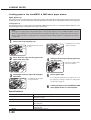
Loading paper in the stand/MPD & 2000 sheet paper drawer
Upper paper tray:
The upper paper tray is equivalent to the multi purpose drawer. The method of loading paper and the paper that can be
used are the same as for the multi purpose drawer. Read the description of the multi purpose drawer (see page xxxx).
Lower paper tray:
The lower paper tray is a large capacity tray that holds 2,000 sheets of 8-1/2" x 11" or A4 paper (20 lbs. (80 g/m2)). Use
the following procedure to load paper in the large capacity tray.
NOTE
If the paper size or paper type is changed when paper is set in the upper paper tray of the stand/MPD & 2000 sheet paper
drawer, the tray settings in the custom settings must be changed. (If the paper type is changed in the large capacity tray,
the tray settings must also be changed.) Be sure to change the setting referring to “Method of setting paper size and type”
on page xxxx.
1
Pull out the large capacity tray.
●
Gently pull the tray out until
it stops.
2
Press down the right and left paper feed
tables until they stop.
4
Load paper onto the left
paper feed table.
Gently push the large capacity paper tray
into the printer.
Push the tray firmly all the
way into the printer.
3
Load paper onto the right and left paper
feed tables.
●
Load paper onto the right
paper feed table.
5
Set the paper type.
6
Loading of paper in the stand/MPD & 2000
sheet paper drawer is now complete.
If you change the paper type in the tray, be sure to set
the paper type referring to “Method of setting paper
size and type” (page xx).
Specifications
Name
Paper sizes
Paper weight
Paper capacity (ordinary paper)
Dimensions
Weight
1-24
Stand/MPD & 2000 sheet paper drawer
Upper tray: Max. 11" x 17" (A3), Min. 5-1/2" x 8-1/2" (A5R), Lower tray:
8-1/2" x 11" (A4)
15 lbs. - 28 lbs. (56 - 105 g/m2)
Upper tray: 500 sheets (20 lbs. (80 g/m2)), Lower tray: 2,000 sheets (20
lbs. (80 g/m2))
23-1/32" (W) x 20-7/8" (D) x 15-29/32" (H) (585 mm (W) x 530 mm (D) x
404 mm (H))
Approximately xxxx kg
ADDING TONER
When toner runs out, a message indicating need to replace the toner cartridge will appear. Also depending on the
model, a message indicating need to replace the developer cartridge may appear.
For the procedure of replacement of these cartridges, see the separate manual "Supply Replacement Method."
1
STORAGE OF SUPPLIES
Standard supplies for this product that are to be replaced by the user are paper, toner cartridge, and staple cartridge for
the finisher.
For best copying results, be sure to use only Sharp Genuine Supplies which are designed,
engineered, and tested to maximize the life and performance of Sharp copiers. Look for the
Genuine Supplies label on the toner package.
GENUINE SUPPLIES
■ Proper storage
1 Store the supplies in a location that is:
clean and dry,
at a stable temperature,
not exposed to direct sunlight.
●
●
●
2 Store paper in the wrapper and lying flat.
Paper stored in packages standing up or out of
the wrapper may curl or become damp, resulting
in paper misfeeds.
●
1-25
CHAPTER 2
PRINTING FROM A COMPUTER
This chapter describes how to install and how to use the printer drivers
and printer utilities on a computer. This chapter also describes the job
retention function that allows print start operation from the operation
panel of the printer.
Page
CONNECTING TO A COMPUTER ........................................................
SOFTWARE FOR WINDOWS ................................................................
INSTALLING PRINTER DRIVERS AND PRINTER UTILITIES .............
REMOVING PRINTER DRIVERS AND PRINTER UTILITIES ...............
INSTALLING PRINTER DRIVERS USING THE PLUG &
PLAY FEATURE OR ADD PRINTER WIZARD .....................................
● Before installation ...........................................................................
SETTING THE PRINTER DRIVER ........................................................
● Setting print conditions under Windows
(selecting and setting print conditions) ...........................................
REMOTE OPERATION THROUGH NETWORK ...................................
● Environment required for accessing Web pages ...........................
● Accessing Web pages and displaying help ....................................
● Items and outline of menu frame of Web pages .............................
JOB RETENTION FUNCTION WHICH ALLOWS PRINT START
OPERATION FROM THE OPERATION PANEL .....................................
● Print functions selectable in the “JOB CONTROL”
dialog box and their operation ........................................................
● Printing method of hold job list ........................................................
● Printer account control ....................................................................
2-2
2-2
2-3
2-3
2-4
2-4
2-5
2-5
2-6
2-6
2-6
2-7
2-9
2-9
2-10
2-12
2-1
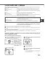
CONNECTING TO A COMPUTER
1. Using this machine as a local printer
When using this machine as a local printer, connect your computer to the parallel interface connector of this
product as shown in the illustration.
For a connection cable, prepare a Centronics cable on the market that conforms to the following specifications.
The parallel interface of this machine conforms to IEEE-STD-1284-1993.
Connector type on this printer: 36-pin DDK 57LE-40360-730B (D29)
female connector or equivalent connector
18
1
36
19
For the specifications of the parallel interface
connector on the computer, see the computer
manual.
Parallel interface connector
2. Using this machine as a network printer
For using this machine as a network printer, a print server card is needed.
See the operation manual supplied with the print server card.
SOFTWARE FOR WINDOWS
When using this product in Windows environment, you must install a printer driver in your computer system. Use the
supplied CD-ROM for installation. For using this product, either connection through a parallel interface connector (see
page xxxx) between the computer and this machine (local printer) or network connection that uses a print server card
(network interface card) as a peripheral unit can be performed.
The print server card may be installed as a standard component or optional depending on the model. Contact your
SHARP dealer.
The following software for Windows is contained in the CD-ROM.
● Printer drivers
● Printer utilities
● Installer
These are software for installing the printer drivers and printer utilities. If you use the Plug and Play feature or the
Add Printer wizard to install the driver without using the installer, specify directly the folder name referring to the
directory information of the PRINTER UTILITIES CD-ROM on page xxxx.
■ Printer drivers
■ Printer utilities
● PCL printer drivers (PCL5e and PCL6)
●
●
●
Optional PostScript printer driver (compatible to
PostScript level 3) and SHARP AR-xxxx PPD file
(PostScript Printer Description file)
Printer Administration Utility
Printer Status Monitor
● Display Font
1. Printer drivers
A printer driver is software designed to convert print data from any application into data understandable by the
printer so that the printer can print out the data. This product, therefore, can be used as a printer only after a printer
driver has been installed. If a printer driver is installed once, it is built into your computer system. You need not
install the driver each time you execute printing.
2. Printer utilities
Printer Administration Utility that allows setting and monitoring of printers on a computer and Printer Status Monitor
that allows monitoring of printer status and display and notification on a computer are provided for network
environment. (only in the Windows environment)
For use of Printer Administration Utility and Printer Status Monitor, see the help file. The details of use are written
in each help file.
Printer Administration Utility is software for system administrators.
2-2
INSTALLING PRINTER DRIVERS AND PRINTER UTILITIES
Windows software
PCL printer drivers
Display font
Windows client
Printer Status
Monitor
Network administrator
Network Administration Utility
The following software can be installed from the installer
supplied in the CD-ROM :
● PCL printer drivers (PCL5e and PCL6)
● Display font
● Printer Administration Utility
● Printer Status Monitor
NOTE
If you wish to install a printer driver or a printer
utility from a floppy disk, see the README file of
the CD-ROM.The method of copying printer drivers
and printer utilities from the CD-ROM to a floppy
disk and the method of use are described.
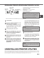
Execute installation from the CD-ROM using the following procedure.
1
2
3
4
Start Windows.
If you click the [README display] button, the
information of the specified software will be
displayed. When installing the Printer
Administration Utility and the Printer Status
Monitor, read the README display and
check to see if the computer system
requirements are satisfied.
Insert the supplied CD-ROM into a CDROM drive of your computer.
If your computer is configured for auto start
on the CD-ROM, the software license
agreement described in step 5 will appear.
(Steps 3 and 4 are not needed.)
NOTE
The Printer Administration Utility and the Printer
Status Monitor can be used only if this product is
used as a network printer.
On the [Start] menu, click “Run.”
Enter the CD-ROM drive and setup
command. Then click the [OK] button.
Example: If the CD-ROM drive is designated as
drive R, enter “R:\SETUP.EXE”.
5
Read the software license agreement and
click the [Next] button if you accept the
agreement.
6
The printer drivers and printer utilities that
can be installed from the CD-ROM will be
listed. Select the check boxes of the
desired drivers and utilities and click the
[Next] button.
7
8
Click the [Start] button.
The installation screen of the file selected with
a check box will appear. Follow the
instructions on your screen to install the
selected printer drivers and utilities.
When installation is complete, the message
“Setup has finished installing your
selected package(s).” will appear. Click the
[Close] button.
NOTE
Restart of your computer may be needed
depending on the system. Click [Yes] to restart
the computer.
UNINSTALLING PRINTER UTILITIES
When uninstalling a printer driver that has been installed, right-click the printer to be deleted from “Printers” of “Control
Panel” and select [Delete]. When uninstalling the Printer Administration Utility or the Printer Status Monitor, use “Add/
Remove Programs” of “Control Panel”. Use the Windows standard operation for each case.
2-3
2
INSTALLING PRINTER DRIVERS USING THE PLUG
& PLAY FEATURE OR ADD PRINTER WIZARD
Before installation
Before installing the printer drivers, check the following items.
● Ensure that your computer system meets the following requirements.
Computer type:
Operating system:
IBM PC/AT or compatible computer
Windows 95
Hardware requirements of the operating system must
Windows 98
be satisfied.
Windows 2000
Windows NT 4.0
Windows Me
When using the Plug and Play feature in the Windows 95/98 environment or using the Add Printer wizard to install
printer drivers, enter the directory name indicated below as a source directory.
Path for using PCL5e driver under Windows 2000
R:\AR-Tigeokamptor\Option\English\2k_pcl5e
Path for using PCL6 driver under Windows 2000
R:\AR-Tigeokamptor\Option\English\2k_pcl6
Path for using PCL5e driver under Windows 95/98/Me
R:\AR-Tigeokamptor\Option\English\9x_pcl5e
Path for using PCL6 driver under Windows 95/98/Me
R:\AR-Tigeokamptor\Option\English\9x_pcl6
Path for using PCL5e driver under Windows NT
R:\AR-Tigeokamptor\Option\English\Nt_pcl5e
Path for using PCL6 driver under Windows NT
R:\AR-Tigeokamptor\Option\English\Nt_pcl6
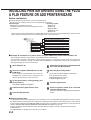
■ Example of installation of a printer driver using the Add Printer wizard under Windows 98
The installation method of a printer driver under Windows 98 is shown below.
The installation example is described assuming that the printer is connected as a local printer (see “Using this
machine as a local printer” on page 2-2) and that the CD-ROM drive is designated as drive R. The procedure may
differ depending on the system environment.
1
2
Start Windows 98.
Insert the supplied CD-ROM into the CDROM drive.
If your computer is configured for auto start on the
CD-ROM, the software license agreement will
appear. Click [Cancel] to close the screen.
3
On the [Start] menu, select [Settings] and
then [Printers].
The Printer window will appear.
4
5
Double-click the [Add Printer] icon.
Click the [Next] button.
6
7
8
9
Check the [Local Printer] radio button and
then click the [Next] button.
Click the [Have Disk] button.
The “Install From Disk” dialog box will appear.
Enter the file path as follows:
R:\Option\English\9x_pcl5e or
R:\Option\English\9x_pcl6
Click the [OK] button.
Select the printer model to be used and
click the [Next] button.
Follow the instructions displayed by the Add Printer
wizard.
■ Installing display fonts
The display fonts are the fonts displayed on your computer screen. The CD-ROM supplied with this product contains
the display fonts that correspond to the resident fonts (page xxx) of this product. These display fonts can be installed
to your computer (Windows 95/98/Me/NT/2000) from the installer. Installation of the display fonts can be specified in
step 6 of “INSTALLING PRINTER DRIVERS AND PRINTER UTILITIES” on page 2-3.
To install the display fonts by Windows basic operation without using the installer, specify the following path.
R:\Option\Fonts
The CD-ROM drive is designated as drive R as an example.
2-4
SETTING THE PRINTER DRIVER
This section describes the method of changing the printer driver settings for using this product properly from your
computer.
If no printer driver has been installed, use the supplied CD-ROM to install it referring to “INSTALLING PRINTER
DRIVERS AND PRINTER UTILITIES” on page 2-3.
Setting print conditions under Windows (selecting and setting print conditions)
Change the settings using the properties of the printer.
■ Windows NT 4.0 / 2000
■ Windows 95 / 98 / Me
Screens under Windows 98 are used in the description
below.
1
On the [Start] menu, select [Settings] and
then [Printers].
Screens under Windows NT 4.0 are used in the
description below.
1
The Printer window will appear.
The Printer window will appear.
2
Right-click the installed printer driver and
select [Properties].
2
Set each item.
3
For setting items, see
the printer driver help.
4
Click the [OK] button.
Right-click the installed printer driver and
select [Document Defaults].
This example is the screen displayed by selecting
AR-P350PCL5e.
This example is the screen displayed by selecting
AR-P350PCL5e.
3
On the [Start] menu, select [Settings] and
then [Printers].
Set each item.
For setting items, see
the printer driver help.
4
Click the [OK] button.
NOTE
For the setting concerning peripheral units such as the duplex module, finisher, and stand/3 x 500 sheet paper
drawer, right-click the installed printer, select [Properties], and then open the [Configuration] tab. If you use this
product as a network printer and you have installed the Printer Status Monitor, the configuration of peripheral units
will be automatically set by clicking “Auto Configuration”. If you click the [Get Tray Status] button in the Detail
dialog box of the Paper tab, the current tray information (paper size, paper type, and quantity of paper remaining)
will be displayed.
2-5
2
REMOTE OPERATION THROUGH NETWORK
If you access the Web pages of this product from your computer using a WWW browser such as Netscape Navigator
and Internet Explorer, various settings can be adjusted through the network.
Environment required for accessing Web pages
The following products and computer system requirements are needed for accessing the Web pages of this product.
● Optional print server card (network interface card)
● Recommended Web browser
Microsoft Internet Explorer 4.0 or later or equivalent
Netscape Navigator 4.0 or later or equivalent
NOTE
The following characters cannot be input in the Web pages when setting the Web pages in the Web server
located in this product. Input characters are case-sensitive.
● Characters that cannot be input:
<> & " #
● Examples of improper input:
<abc> <abc "abc" "abc
abc
<
>
|
Accessing Web pages and displaying help
Use the following procedure to access the Web pages. If the help button under the menu frame is clicked, the help
screen for description of various function settings that can be operated remotely from the Web pages for this product
through the network will appear. For the setting of each function, see this detailed description.
1
2
Open the Web browser on your computer.
3
Click the [Help] button under the menu
frame.
Input the IP Address previously specified
for this product to the ADDRESS field of
the browser.
Input the IP address
previously specified in
this product. (See page
xx.)
When the connection is
completed, the Web page
information of this product
will be displayed.
2-6
For details of each
function setting, see the
help under the menu
frame. The method of
setting is described in
detail.
4
Close the help.
Click the
button. The
display will return to the
Web page information of
this product.
REMOTE OPERATION THROUGH NETWORK
Items and outline of menu frame of Web pages
Destination Management
The basic screen on which you can register, change, and delete the destination for image data scanned by the network
scanner and the recipient information for facsimile and Internet facsimile (destination address, facsimile number, etc.) is
described below.
■ Setting of E-mail Destination Control
Sets the destination information for E-mail delivery scan of network scanner.
Destination E-mail addresses and file types as well as information for destination control (destination name, index,
name for front panel display, etc.) are set.
2
NOTE
When performing E-mail destination setting, be sure to read the description on page xxxx in advance.
■ Setting of FTP Destination Control
Sets the storage location information for file server storage scan of network scanner. File server information (such
as host name) and file types as well as information for destination control (destination name, index, name for front
panel display, etc.) are set.
■ Setting of Desktop Destination Control
Sets the destination information for desktop delivery scan of network scanner. Destination computer information
(such as host name) in which the network scanner tool/Sharpdesk has been installed and file types as well as the
information for destination control (destination name, index, name for front panel display, etc.) are set.
■ Setting of Fax Destination Control
Sets the fax destination. Fax numbers of recipients and communication mode as well as information for destination
control (destination name, index, name for front panel display, etc.) are set.
■ Setting of i-Fax transmission Destination Control
Sets the Internet fax destination information. E-mail addresses of destination and file types as well as information
for destination control (destination name, index, name for front panel display, etc.) are set.
■ Setting of Group Destination Control
Sets destination groups for transmitting data at a time by collecting destinations that have been set as E-mail
destination, fax destination and i-fax destination.
■ Delete Destination
Screen for checking to see if deletion may be executed after selecting a destination to be deleted from the destination
list on the destination management screen and clicking the Delete button.
Fax Memory Box Management
Basic screen for setting memory area (memory box) for fax images in this product. The memory box has the
following three functions.
● Polled memory box control
● Memory box relay broadcast control
● Confidential memory box control
■ Polled Memory Box Control
Original data that has been stored in this machine can be transmitted to another facsimile when the facsimile
requests transmission.
■ Confidential receiving
Data to be printed is sent to this machine and printing can be operated from the operation panel of this machine.
■ Relay broadcasting
Memory box information for transmitting received data can be set.
2-7
REMOTE OPERATION THROUGH NETWORK
Set up
Setting of restriction on access to Web pages and basic settings for using the network scanner and the status/alert
E-mail function are described below.
■ Network Card Setup
A link to the network card Web page for setting the print server card (network interface card) is provided.
■ Password Setup
A password for accessing the Web pages is set. Two types of password (user level and administrator level) are set.
■ Network Scanning Setup
Basic setting screen for network scanner. E-mail subject for scanner delivery, file name, etc. are set. To use the
network scanner, you must set up E-mail & DNS Setup. This screen displays the settings of E-mail & DNS Setup
and provides a link to the screen.
■ Status & Alert E-mail Setup
Basic setting screen for the status/alert E-mail system. Machine name, machine code, and machine installation
location are set. To use the network scanner, you must set up E-mail & DNS Setup. This screen displays the settings
of E-mail & DNS Setup and provides a link to the screen.
■ E-mail & DNS Setup
Basic setting screen for transmitting E-mail. E-mail server, system administrator address, DNS server, etc. are set.
■ Sender of E-mail Setup
Sender of E-mail transmission of the network scanner is set. This item will be set as the “From” item of E-mail
header. Up to eight senders can be registered and a sender can be selected among them from the operation panel.
■ Custom Directory Setup
Group index names in the list display on the operation panel are set.
■ Status Message Parameters Setup
Used when the current counter information of this machine such as print count, copy count, and total output is
delivered in accordance with the specified schedule.
■ Alerts Message Parameters Setup
Alert information is transmitted immediately to the specified addresses when a problem of supplies such as paper
and toner, failure, and an error such as a paper misfeed occur in this machine.
2-8
JOB RETENTION FUNCTION WHICH ALLOWS PRINT
START OPERATION FROMTHE OPERATION PANEL
This section describes the operation procedure required for starting printing from the operation panel of the printer and
the outline of the function concerning the print functions that can be selected in the “JOB CONTROL” dialog box using
the printer drivers of this product. For selection of the print function, select “Properties” on the printer driver screen,
open the “Main” tab, and click “Job control.” The job retention function can be used only if this printer is equipped with
a hard disk drive as a peripheral unit.
Print functions selectable in the "JOB CONTROL" dialog box and their operation
1
Normal print
(For “Normal print”, print start operation from the
operation panel of the printer is not needed.)
4
2
This mode can prevent a high-volume misprint when
a lot of sets must be printed. If print start operation
is executed in this mode, only one set will be printed
and the remaining sets will be held as a hold job.
After checking the finished printout including print
position on paper and stapling position, you can
start printing of the remaining sets from the
operation panel of the printer. Also you can delete
the data without executing printing. (See step 8 on
page xx.)
The print setting in this mode is the basic print
operation. If no problem such as a paper misfeed
and empty toner occurs in the printer, the print start
operation is completed on the computer and printing
will be executed on the printer.
2
Proof print
Hold after print
5
Password
Password
In this mode, print data will be held in the hold job
list even after printing is complete. Printing can be
executed again from the operation panel of the
printer if needed. Also the data can be deleted from
the operation panel if it is not necessary.
3
Hold before print
This print mode can reduce the possibility of
missing printout. If print start operation is made in
this mode from the computer, print data will not be
output immediately and will be stored in the printer
as a hold job.
Print start operation can be made on the operation
panel of the printer as needed. Also you can delete
the data without executing printing. (See step 8 on
page xx.)
Password
If a password is set in the printer driver setting,
password entry is needed to start printing of a
holdThis mode can increase the security of hold
jobs.his mode can increase the security o hd jobs.
● Password in the Hold After Print mode:
Password entry on the operation panel of the
printer is needed for additional printing.
● Password in the Hold Before Print mode:
Password entry on the operation panel of the
printer is needed for starting printing.
● Password in the Proof Print mode:
Password entry on the operation panel of the
printer is needed for printing remaining sets after
printing one set.
2-9
JOB RETENTION FUNCTIONWHICH REQUIRES PRINT START OPERATION FROMTHE OPERATION PANEL
Printing method of hold job list
If “Print after hold”, “Print before hold” or “Proof print” operation is performed on the computer, print data will be held as
a hold job. (Up to 100 jobs can be held.)
If the number of jobs exceeds 100, the job is processed as follows.
● If Hold After Print is executed:
Printing will be executed but the job will not be held. (A notice page will be printed. See page xx.)
● If Hold Before Print is executed:
Printing will not be executed and the job will not be held. (A notice page will be printed. See page xx.)
● If Proof Print is executed:
Printing of one set will be executed but the job will not be held. (A notice page will be printed. See page xx.)
When using the operation panel on the main unit:
For operation from the operation panel with touch panel, see the next page.
●
1
2
Press the [MENU] key.
3
(needed only if a password has been set)
Be sure to enter the number that has been entered
on the computer. If no password has been set,
operation of steps 5 and 6 is not needed. (Proceed
to step 7.)
If you press the [OK] key
PASSCODE
to register the fifth digit
0
after entering it using the
or
key on the
operation panel, “0” will
appear at the fourth digit.
If you press the [BACK/
C] key, you can correct
the entered number.
When the [OK] key is
pressed, a user name and
a file name of print data
6
Use the same procedure as step 5 to enter
the password from the fourth digit to the
first digit and then press the [OK] key.
stored in the printer as
a hold job will appear.
PASSCODE
0
Select the desired data.
Press the or key on
the operation panel
repeatedly until the
desired print data is
displayed.
4
Enter the fifth digit of the password and
press the [OK] key.
“PRINT HOLD” will
appear in the message
display.
Press the [OK] key.
ARAI
WORD-1
5
Press the [OK] key.
7
Select execution of printing, cancellation
of printing or data retention after printing,
and then press the [OK] key.
Deletion or retention of data after printing can be
selected. Alternatively deletion of data without
printing can be selected. Press the
or
key
until the desired choice appears
PRINT AND DELETE THE
DATA OK?
PRINT AND SAVE THE
DATA OK?
DELETE THE DATA OK?
2-10
Use the same procedure
as above (fifth digit) to
enter the fourth digit to the
first digit.
●
Data will be deleted
after printing.
●
Data will be held after
printing.
●
Data will be deleted.
If this item is selected,
the operation will be
complete. Steps 8 and
9 are not needed.
JOB RETENTION FUNCTIONWHICH REQUIRES PRINT START OPERATION FROMTHE OPERATION PANEL
Ensure that the desired number of copies
is set.
The number of copies
COPIES
can be changed by
10
using the or key on
the operation panel.
8
Press the [OK] key.
9
●
10
Printing will start. If printing of another job is
being executed, however, your job will be
registered as a print job. Printing of the job
will start after preceding jobs are completed.
2
Operation is now complete.
To continue operation, repeat steps 1 to 9.
When using the operation panel with touch panel:
Press the [PRINT] key to display the printer
basic screen.
1
4
Select execution of printing, cancellation
of printing or data retention after printing.
NUMBER OF PRINTS
1
2
Select the desired data.
●
To switch the screen,
touch the or key.
PRINT HOLD JOB LIST
SHARP001
SHARP002
SHARP003
The number of copies
has been set. The
number of copies can be
changed by using the
or
key.
SHARP004
3
(1 199)
Deletion or retention of
data after printing can
PRIN be selected.
Alternatively deletion of
PR data without printing
can be selected. Touch
the desired key.
Enter the password.
(needed only if a password has been set)
ENTER PIN VIA THE 10-KEY.
CANCEL
Be sure to enter the
password that has
been entered on the
computer. If
no
password has been
set, operation of step 4
is not needed.
5
Printing will start. If
printing of another job
is being executed,
however, your job will
be registered as a
print job. Printing of
the job will start after
preceding jobs are
completed.
Operation is now complete.
Each time a number is
entered, “–” will change to
“ ”.
2-11
JOB RETENTION FUNCTIONWHICH REQUIRES PRINT START OPERATION FROMTHE OPERATION PANEL
Printer account control
If the key operator program “Auditing mode” is set, the number of printed pages can be accumulated for each account.
The accounts for auditing are the accounts that have been set for counting the number of pages for the printer with a
key operator program. For registration of account numbers, see the key operator programs (page xxxx).
When executing print operation from the computer, you must enter an account number on the setting screen of the
printer driver. The account number entry screen will be displayed by clicking “Job control” in the “Main” tab of the printer
driver.
When an invalid account number is entered or no account number is entered, if key operator program “Cancel jobs of
invalid accounts” has been set, printing will not be performed. To perform printing in any case, disable program “Cancel
jobs of invalid accounts”. In this case, the number of printed pages will be accumulated to “OTHERS”.
The job control screen will always appear when print operation is executed from the printer driver if the “Auto Job
Control review” check box in the “Main” tab of the printer driver is set.
2-12
CHAPTER 3
PRINTER BASIC SETTINGS
This chapter describes the following items.
1. Printer configuration settings
2. Custom settings based on the customer’s operating conditions.
Page
MAKING CONFIGURATION SETTING ..................................................
● Operation procedure common to all printer configuration settings
(items that can be set from the operation panel) ............................
● Main program settings .....................................................................
● PCL settings ....................................................................................
● PostScript settings ...........................................................................
CUSTOM SETTINGS .............................................................................
● Operation procedure common to all custom settings
(items that can be set from the operation panel) ............................
● Setting items ....................................................................................
3-2
3-2
3-4
3-4
3-4
3-5
3-5
3-7
3-1
MAKING CONFIGURATION SETTING
The printer configuration setting allows basic printer settings to be made. The items set with the printer configuration
settings are shown below.
● Main program settings ..................... Basic settings used in printing (See page xxxx.)
● PCL settings ................................... Sets a PCL symbol set. (See page xxxx.)
● PostScript settings*1 ....................... Sets whether a PostScript error page is printed or not when a PostScript error
has occurred. (See page xxxx.)
*1 An optional PS3 expansion kit is needed.
Operation procedure common to all printer configuration settings
(items that can be set from the operation panel)
When using the operation panel on the main unit:
1
Press the [MENU] key to display the
configuration setting menu screen.
Press the [MENU] key
repeatedly
until
“CONDITION SETTING”
appears.
Any print jobs held in the
printer and any job
currently transmitted to
the printer will be printed
in the former print
conditions.
2
5
6
3
4
Press the [OK] key.
3-2
key to display the desired
Press the [OK] key.
●
will be displayed to the
right of the selected item
and setting will be
registered. To set another
item, press the [BACK/C]
key to return to step 3 and
repeat the procedure to
step 6.
7
key to display the desired
or
For the details of each setting item, see the
description on and after page xxxx.
Press the [OK] key.
Press the or
setting item.
Press the
setting.
When setting is complete, press the
[MENU] key to return to the basic screen.
NOTE
If the [BACK/C] key is pressed after each setting is
complete, the display that has called the setting
will appear again. If selection of a number is mistaken
during setting operation, press the [BACK/C] key to
correct the selected number.
MAKING CONFIGURATION SETTING
When using the operation panel with touch panel:
1
Touch the [CONDITION SETTINGS] key
on the printer screen to display the
configuration setting menu screen.
CONDITION
SETTINGS
2
Any print jobs held in the
printer and any job
currently transmitted to
the printer will be printed
in the former print
conditions.
Touch the key of the desired item to display
its setting screen.
3
CONDITION SETTINGS
MAIN PROGRAM SETTINGS
PCL SETTINGS
PostScript SETTINGS
For details of each setting item, see the description
on and after the next page.
Depending on the setting item, additional item
setting keys may be displayed or page switching
keys may be displayed.
If a check box is displayed for an item, the item
can be set by touching the key to display a check
mark ( ) in the box.
3
Touch the desired setting on the setting
screen of the desired item and touch the
[OK] key.
To set another item, repeat steps 2 and 3.
4
To finish the setting operation, touch the
[EXIT] key.
3-3
MAKING CONFIGURATION SETTING
Main program settings
The main program settings allow detailed print conditions to be set for printing without any printer driver (for example,
printing from MS-DOS and printing from a computer without any printer driver installed). The setting items are shown
below.
NOTE
When some items can be set both in the printer driver and on the operation panel, the values set in the printer
driver override those set on the operation panel. For items that can be set in the printer driver, perform setting
in the printer driver.
■ Smoothing
SMOOTHING reduces jaggies seen at roundish
curved portions of characters and images to be
printed and improves pseudo resolution.
Default setting: On
Smoothing on or off can be selected.
■ Copies
COPIES is set when the number of copies to be
printed is set.
Default setting: 1
The number of copies can be set from 1 to 999.
■ Orientation
ORIENTATION allows portrait orientation or
landscape orientation to be selected for printing.
Default setting: PORTRAIT
PORTRAIT or LANDSCAPE can be set.
■ Standard paper size
The paper size to be used for printing in the normal
conditions is set.
Printing will be performed onto the specified size
paper unless otherwise specified.
Default setting: 8-1/2 x 11 or A4
11 x 17, 8-1/2 x 14, 8-1/2 x 13, 8-1/2 x 11, 7-1/4 x 10-1/2, 5-1/
2 x 8-1/2, A3, B4, A4, B5 or A5 can be set.
(If the operation panel on the main unit is used, the
sizes are displayed as follows in the display:
LEDGER, LEGAL, FOOLSCAP, LETTER,
EXECUTIVE, INVOICE, A3, B4, A4, B5, and A5.)
■ Standard paper type
The paper type to be used for printing in the normal
conditions is set.
Printing will be performed onto the specified type
paper unless otherwise specified.
Default setting: PLAIN
Plain paper, pre-printed paper, recycled paper, letter
head paper, pre-punched paper or color paper can
be set.
■ Standard output tray
The output tray to be used for printing in the normal
conditions is set. Printed sheets will be output to the
specified tray unless otherwise specified by
application software.
Default setting: Depends on installation of peripheral
unit.
The trays that can be selected depend on installation
of peripheral units. This item itself may not be
selected.
PCL settings
PCL SETTINGS is used to assign a part of character codes to characters of a country in the PCL symbol set. (Used
when different symbols are used depending on the country.)
Default setting: “1” (Roman-8)
For setting items of the symbol set, see page xxxx.
The list of the numbers to be set and their corresponding symbol sets can be printed using “PCL symbol set list
printing” (see page xxxx).
When using the operation panel on the main unit, select the desired symbol set item and register it. When using the
operation panel with touch panel, select the number that corresponds to the desired symbol set and register it.
PostScript settings
This setting specifies whether the cause of an error is printed or not when a PostScript error has occurred.
Default setting: Not print
Print or not print can be selected concerning the cause of a PS (PostScript) error.
3-4
CUSTOM SETTINGS
Custom settings are used for various settings based on the customer operating conditions. The items that can be set
with the custom settings are shown below.
● Total count ....................................... The number of printed pages and the like are displayed. (See page xxxx.)
● Display contrast*1 ........................... The display contrast of the operation panel is adjusted. (See page xxxx.)
● List print .......................................... Used to print a list of settings that have been made or a font list. (See page
xxxx.)
● Clock ............................................... The date and time of the built-in clock of the printer are set.
● Tray settings*4 ................................. The paper type and paper size for each tray are set.
● Auto tray switching .......................... Used to switch automatically the paper tray of the same paper size when
paper runs out in continuous printing.
For the items below, detailed setting procedure is described on the respective pages of the functions.
● Address control*3 ....................... Used to register destination E-mail addresses, fax numbers, and Internet
fax addresses. Also group entry, memory box entry, custom index entry,
and scanner sender entry can be set.
● Receive mode*2 ......................... The fax receive mode (automatic or manual) is set.
● Fax data forward*2 ...................... Received fax data in memory can be forwarded to another destination.
● Key operator programs .................... RSetting programs are provided for key operators (administrators of this
machine). If this product is equipped with a scanner module as a peripheral
unit, this key will appear in the CUSTOM SETTINGS menu screen. For settings,
see Key Operator’s Guide. (See page xxxx.)
1 Can be set if this product is equipped with a scanner module as a peripheral unit.
2 Can be set if this product is equipped with a scanner module as a peripheral unit and the facsimile feature can be
used.
3 Can be set if this product is equipped with a scanner module as a peripheral unit and the facsimile feature or the
network scanner feature can be used.
4 Can be set with this item if this product is not equipped with a scanner module as a peripheral unit.
Operation procedure common to all custom settings (items that can be set
from the operation panel)
When using the operation panel on the main unit:
1
Press the [MENU] key to display the
custom settings menu screen.
Press the [MENU] key
repeatedly until the
message “CUSTOM
SETTINGS” appears.
Any print jobs held in the
printer and any job
currently transmitted to
the printer will be printed
in the former custom
setting conditions.
2
Press the [OK] key.
3
Press the or
setting item.
4
5
Press the [OK] key.
Press the
or
key to select the desired
key to select the desired
setting.
For details of each setting item, see the description
on and after page xxxx.
3-5
3
CUSTOM SETTINGS
6
Press the [OK] key.
“ ” will be displayed to
the right of selected item,
and the setting will be
registered. Depending on
the
setting
item,
additional item selection
and registration operation
may be needed. In this
case, use the or key
to select an item and
press the [OK] key to
register it. To set another
item, press the [BACK/C]
key and repeat steps 5
and 6.
7
When setting is complete, press the
[MENU] key to return to the basic screen.
NOTE
If the [BACK/C] key is pressed after each setting
is complete, the display that has called the setting
will appear again. If selection of a number is
mistaken during setting operation, press the [BACK/
C] key to correct the selected number.
When using the operation panel with touch panel:
1
Press the [CUSTOM SETTINGS] key when
the printer screen is displayed to display
the custom settings menu screen.
3
Touch the desired setting on the setting
screen of the desired item and touch the
[OK] key.
Any print jobs held in the
printer and any job
currently transmitted to
the printer will be printed
in the former custom
setting conditions.
2
Touch the key of the desired item to display
its setting screen.
DISPLAY
LIST PRINT
CLOCK
TRAY SETTINGS
ADDRESS
RECEIVE MODE
FAX DATA
KEY OPERATOR PROGRAMS
For details of each setting item, see the description
on and after the next page.
CUSTOM SETTINGS
TRAY SETTINGS
OK
TYPE / SIZE
PRINT
COPY
FAX
1/2
1/
2
TRAY 1
PLAIN / 8 X11
TRAY 2
PLAIN / AUTO-INCH
TRAY 3
RECYCLED / AUTO-INCH
Depending on the setting item, additional item setting
keys may be displayed and page switching keys
may be displayed.
If a check box is displayed for an item, the item can
be set by touching the key to display a check mark
( ) in the box.
3-6
OK
TYPE / SIZE
PRINT
COPY
FAX
1/2
1/
2
TRAY 1
PLAIN / 8 X11
TRAY 2
PLAIN / AUTO-INCH
TRAY 3
RECYCLED / AUTO-INCH
To set another item, repeat steps 2 and 3.
4
CUSTOM SETTINGS
TOTAL COUNT
CUSTOM SETTINGS
TRAY SETTINGS
To finish the setting operation, touch the
[EXIT] key.
CUSTOM SETTINGS
Setting items
■ Total count
The number of total printed pages in this product
can be displayed and printed.
The displayed or printed items vary with installation
of peripheral units.
■ Display contrast
Can be set if this product is equipped with a scanner
module as a peripheral unit.
This item is used to adjust the contrast of the touch
panel display.
■ List print
Test pages such as a list of setting items configured
in this product and a list of the resident fonts for
checking can be printed.
The types of test pages are shown below.
● Setting list print
The settings in the printer feature are printed.
● Printer test page
Demonstration page printing: Demonstration
pages contained in this product are printed.
PCL font list printing: A list of fonts that can be
used with the PCL printer drivers is printed.
PCL symbol set printing: A PCL symbol set list
is printed.
NIC page printing: A list of settings used by the
NIC (Network Interface Card), namely the print
server card (peripheral unit), is printed.
PostScript font list printing: A list of fonts that
can be used with the PostScript printer driver is
printed.
■ Tray settings
Paper type, paper size, operation mode, and use of
automatic tray switching are set for each tray.
The operation mode can be set when this product is
equipped with a scanner module as a peripheral unit.
If the product is not equipped with a scanner module,
use the item “Auto tray switching” described below
for setting the automatic tray switching function.
■ Auto tray switching
This item can be set if this product is not equipped
with a scanner module as a peripheral unit.
If the auto tray switching function is set and more
than one tray of the same paper size is installed in
this product, printing can be continued by switching
automatically the paper tray when paper of a tray
runs out. This item is used to enable the auto tray
switching function. If the product is equipped with a
scanner module as a peripheral unit, use the item
“Tray settings” to set this function.
●
●
●
●
●
NOTE
If test page printing is disabled with key operator
program “DISABLE TEST PAGE PRINTING” (page
xx), the printer test pages cannot be printed.
■ Clock
The date and time of the built-in clock of this product
are set.
This setting is needed for date and time information
in E-mail delivery of information of this product (see
page xxxx), date print function in the copy mode
(see page xxxx), timer operations in the fax mode
(see page xxxx), and date and time information
recording of fax transmission and reception (see page
xxxx).
3-7
3
CHAPTER 4
TROUBLESHOOTING
AND MAINTENANCE
This chapter describes misfeed removal, user maintenance, etc.
MISFEED REMOVAL . . . . . . . . . . . . . . . . . . . . . . . . . . . . . . . . . . . . . . . . .
● General misfeed removal procedure . . . . . . . . . . . . . . . . . . . . . . . . .
● Misfeed removal guidance . . . . . . . . . . . . . . . . . . . . . . . . . . . . . . . . .
● Misfeed in the paper feed area . . . . . . . . . . . . . . . . . . . . . . . . . . . . . .
● Misfeed in the transport area, fusing area, and exit area . . . . . . . . .
● Misfeed in the duplex module . . . . . . . . . . . . . . . . . . . . . . . . . . . . . . .
TROUBLESHOOTING . . . . . . . . . . . . . . . . . . . . . . . . . . . . . . . . . . . . . . . .
USER MAINTENANCE . . . . . . . . . . . . . . . . . . . . . . . . . . . . . . . . . . . . . . .
● Cleaning the scanner module . . . . . . . . . . . . . . . . . . . . . . . . . . . . . .
Page
4-2
4-2
4-3
4-4
4-6
4-7
4-8
4-12
4-12
4-1
MISFEED REMOVAL
When using the operation panel on the main unit:
❇ For operation from the operation panel with touch panel, see the next page.
When a misfeed has occurred, the message shown below will appear and printing will stop. Follow the procedure below
to remove misfed paper.
PAPER JAM.
CAUTION
NOTES
● Do not damage or touch the photoconductive drum.
(See page 1-6.)
● Be careful not to tear the misfed paper during
removal.
● If paper is accidentally torn during removal, be sure
to remove all pieces.
The fusing unit is hot. Take
care in removing paper.
Fusing unit
General misfeed removal procedure
If the INFORMATION key is pressed when a misfeed has occurred, the approximate misfeed locations will be
displayed. Use the following procedure to check the misfeed locations and refer to the corresponding misfeed
removal procedure.
1
2
Press the INFORMATION key.
Press the
panel.
or
key on the operation
Each time the
key is
pressed, the misfeed
removal procedure will be
displayed sequentially.
4-2
The messages in the table below show approximate
misfeed locations. For misfeed removal procedure, see
the pages indicated in the table.
Message
SLIDE THE FINISHER FROM MACHINE.
PULL OUT TRAY * AND CHECK THE PAPER.
PULL OUT PAPER FROM BYPASS TRAY.
OPEN THE LOWER LEFT COVER.
OPEN THE DUPLEX COVER.
OPEN THE LEFT COVER.
OPEN THE UPPER PATH.
OPEN THE MAIL-BIN COVER.
OPEN THE FINISHER TOP COVER.
3
Page
Press the INFORMATION key to close the
misfeed removal guidance.
MISFEED REMOVAL
When using the operation panel with touch panel:
When a misfeed has occurred during printing, the message "A MISFEED HAS OCCURRED." will appear in the
touch panel display of the operation panel and printing including copying and facsimile output will stop. The
approximate locations are indicated with " " shown in the illustration below. Refer to the description for the indicated
locations to remove the misfed paper.
Misfeed in the scanner module
(page xxxx)
Misfeed in the finisher (page xxxx)
Misfeed in the mail-bin
stacker (page xxxx)
Misfeed in the transport area, fusing
area, and exit area (page xxxx)
Misfeed in the duplex module
(page xxxx)
Misfeed in the bypass tray (page xxxx)
Misfeed in paper tray 1 (page xxxx)
Misfeed in the multi purpose drawer
(page xxxx)
Misfeed in the stand/MPD & 2000
sheet paper drawer (page xxxx)
Misfeed in the saddle
stitch finisher (page
xxxx)
Misfeed in the
multi purpose
drawer (page
xxxx)
Misfeed in the stand/3 x 500 sheet
paper drawer (page xxxx)
NOTE
● Facsimile reception data is always stored in the memory temporarily. When a misfeed has occurred, the
received data will not be printed. After misfed paper is removed, received data will be automatically printed.
● When removing misfed paper, take care not to apply vibration to the machine. Vibration during scanning
originals may disturb scanning, resulting in partially improper copies or images for facsimile or scanner
transmission.
CAUTION
NOTES
●
Do not damage or touch the photoconductive drum.
(See page 1-6.)
●
Be careful not to tear the misfed paper during removal.
●
If paper is accidentally torn during removal, be sure to
remove all pieces.
The fusing unit is hot. Take
care in removing paper.
Fusing unit
Misfeed removal guidance
Misfeed removal guidance can be displayed by touching the INFORMATION key on the touch panel when a misfeed
has occurred.
INFORMATION
4-3
4
MISFEED REMOVAL
Misfeed in the paper feed area
NOTE
Do not pull out the paper tray first. Paper may be misfed between the paper tray and the paper feed area in the
printer. Before pulling out the paper tray, be sure to open the left side cover and check to see if paper is misfed
(steps 1 and 2). If you pull out the paper tray without checking, paper may be torn and it may be difficult to
remove it.
■ Misfeed in paper tray 1
1
Pull out the duplex module.
2
Remove the misfed paper.
Hold the knob and gently
open the module.
If the machine is not
equipped with the duplex
module, open the side
cover similarly.
Be careful not to tear the
misfed paper during
removal.
NOTE
Since paper may be misfed in the inner part, check
carefully and remove it.
3
If misfed paper is not found in step 2, pull
out paper tray 1 and remove the misfed
paper.
Be careful not to tear the
misfed paper during
removal.
4
Gently close the paper tray.
Push back the paper tray
all the way into the
machine.
4-4
5
Gently close the duplex module.
If the machine is not
equipped with the duplex
module, close the side
cover similarly.
After closing the duplex
module, confirm that the
misfeed message is
cleared and that the
normal display appears.
NOTE
If paper drops beyond the rear side of the paper tray
that has been pulled out, remove the paper tray and
then remove the paper. (For removal of the paper tray,
see the illustration below.)
After pulling out the paper
tray until it stops, gently
lift and pull the tray to
remove it. To reattach the
removed paper tray,
insert it at an angle and
then push it back
horizontally in the reverse
procedure of removal.
MISFEED REMOVAL
■ Misfeed in the multi purpose drawer
1
If the machine is equipped with a stand/
paper drawer, open the side cover of the
stand/paper drawer.
Hold the knob and gently
open the cover.
If the machine is not
equipped with a stand/
paper drawer, proceed to
step 4.
Remove the misfed paper.
2
Be careful not to tear the
misfed paper during
removal.
NOTE
Since paper may be misfed in the inner part, check
carefully and remove it.
3
4
■ Misfeed in the stand/MPD & 2000 sheet
paper drawer
For misfeed removal in the upper tray, follow the
procedure of “Misfeed in the multi purpose drawer”
shown to the left to remove the misfed paper. For
misfeed removal in the lower large capacity tray, follow
the procedure below.
1
2
Follow steps 1 to 3 of “Misfeed in the multi
purpose drawer” shown to the left.
3
If misfed paper is not found in steps 1 and
2, pull out the large capacity tray (lower
tray) and remove the misfed paper.
If misfed paper is not found in step 1, refer
to “Misfeed in paper tray 1” (steps 1 and 2
on page xxxx) to remove the misfed paper.
4
●
If paper is misfed on the right paper feed table:
●
If paper is misfed on the left paper feed table:
Raise the paper guide and
remove the misfed paper.
Close the side cover of the stand/paper
drawer.
If misfed paper is not found in step 2, refer
to “Misfeed in paper tray 1” (steps 1 to 5
on page xxxx) to remove the misfed paper.
4
Gently close the large capacity tray.
5
Gently close the duplex module.
■ Misfeed in the stand/3 x 500 sheet paper
drawer
For misfeed removal in the upper tray and middle and
lower trays, follow step 1 to 4 of the description of
“Misfeed in the multi purpose drawer” above to remove
the misfed paper.
Push back the paper tray
all the way into the
machine.
If the machine is not
equipped with the duplex
module, close the side
cover similarly.
After closing the duplex
module, confirm that the
misfeed message is
cleared and that the
normal display appears.
4-5
MISFEED REMOVAL
Misfeed in the transport area, fusing area, and exit area
CAUTION
The fusing unit is hot. Take care in removing paper.
(Do not touch the metal portion.)
1
2
●
If paper is misfed in the exit area:
Remove the misfed paper
taking care not to tear the
paper.
Pull out the duplex module.
Hold the knob and gently
open the module.
If the machine is not
equipped with the duplex
module, open the side
cover similarly.
Remove the misfed paper.
●
If paper is misfed in the transport area:
Turn roller rotating knob A
Roller rotating knob A
in the direction of the
arrow to remove the
misfed paper.
●
If paper is misfed in the fusing area:
Turn roller rotating knob B
Roller rotating
in the direction of the
knob B
arrow to remove the
misfed paper.
CAUTION
The fusing unit is hot. Take care in removing paper.
(Do not touch the metal portion.)
Fusing unit open tab
4-6
If the misfed paper is
inside the fusing area,
turn down the fusing unit
open tab to your side to
open the fusing unit and
remove the misfed paper.
If the duplex module is
equipped with an exit tray
and paper is misfed in the
exit area, remove the
misfed paper as shown in
the illustration.
3
Gently close the duplex module.
After closing the duplex
module, confirm that the
misfeed message is
cleared and that the
normal display appears.
MISFEED REMOVAL
Misfeed in the duplex module
1
Pull out the duplex module.
2
Raise the exit tray and open the cover of
the duplex module.
3
●
●
Hold the knob and gently
open the module.
If the duplex module is not
equipped with an exit tray,
the operation concerning
the exit tray is not needed
(steps 2 to 4).
5
Gently close the duplex module.
After closing the duplex
module, confirm that the
misfeed message is
cleared and that the
normal display appears.
■ Misfeed in the bypass tray
1
Remove the misfed from the bypass tray.
Be careful not to tear the
misfed paper during
removal.
While holding the exit tray up, remove the
misfed paper.
If paper is misfed at the upper part of the duplex
module:
Gently remove the misfed
paper taking care not to
tear the paper.
2
Open and close the duplex module to clear
the misfeed message.
If paper is misfed at the lower part of the duplex
module:
Gently remove the misfed
paper taking care not to
tear the paper.
4
Close the cover of the duplex module and
return the exit tray.
4-7
4
TROUBLESHOOTING
Always check the message display whenever the printer stops or operation is not possible. The messages will give you
easy-to-follow directions. If the messages do not give specific instructions, check the list below.
This section describes only troubleshooting concerning the printer feature and problems common to all features of this
product. For troubleshooting of the copier, facsimile, and network scanner features, see the respective manuals. Also
for problems in peripheral units, see their respective descriptions.
Problem
Printer does not
operate.
Solution
●
Printer plugged in?
Plug the printer into a grounded outlet.
●
Main power switch on?
Turn on the main power switch.
●
READY indicator on?
The printer is warming up. (Warm-up time
is approximately 95 seconds.) Wait until
the READY indicator lights up.
●
Message indicating need to load
paper displayed? (ERROR indicator
lit at the same time on the operation
panel of the main unit?)
Load paper. (page xxxx)
●
Message indicating need to replace
the toner cartridge displayed?
(ERROR indicator lit at the same
time on the operation panel of the
main unit?)
Toner runs out. Replace the toner
cartridge immediately. (page xxxx)
●
Message indicating a paper misfeed
displayed? (ERROR indicator lit at
the same time on the operation
panel of the main unit?)
Remove misfed paper. (page xxxx)
●
Is the correct interface cable properly
connected between the printer and
your computer?
Ensure that the correct interface cable is
connected between the printer and your
computer.
●
Is the correct printer driver installed?
●
Is the printer not selected properly or
not registered on the network (when
used as a network printer)?
Install the appropriate printer driver. (page
xxxx)
Ensure that this printer is selected on the
application software or use an appropriate
utility to check that the printer is registered
on the network.
Data is received but
not printed. (DATA
indicator blinks.)
●
Has an error occurred?
Check to see if an error message is
displayed in the message display.
●
Is the specified size paper loaded in the
printer?
Load paper, select another paper size or
cancel printing.
Printer cannot be
selected from
computer.
●
Is the printer driver installed
correctly?
Install the printer driver correctly. (page
xxxx)
Incorrect orientation
●
Is the orientation setting in the
printer driver correct?
Correct the orientation in the printer driver.
Paper image is clipped
or off the edge of
paper.
●
Zoom printing?
Use the proper magnification ratio for
printing.
Printer is on but data
is not received.
4-8
TROUBLESHOOTING
Problem
Black pages
Solution
●
Is color image data printed?
Color image may be printed in black.
●
Are the black and white areas
reversed?
Cancel negative image printing feature in
the printer driver.
Image loss along the
edges
●
Is the image loss outside the print
area?
Change the print area (page xxxx) or
reduce the print image.
Printer prints in
reverse order.
●
Is the reverse order selected in the
application software?
Cancel the reverse order printing in the
application software.
Printer stops in the
middle of a print job.
●
Too much paper in the exit tray?
(page xxxx)
Remove the paper from the exit tray.
●
Has the paper runs out?
Load paper.
Paper specified from
application is not used.
●
Is paper selection of driver "Auto"?
Ensure that the desired paper is set in a
paper tray of the printer and select "Auto"
in the paper selection of the printer driver.
Printer resident font
cannot be selected
from application
software (when the
PPD file of an optional
PS3 expansion kit is
used in Windows (not
NT) environment).
●
Has the resident font information
installed?
Install (or reinstall) the resident font
information. If installed resident font
information may be damaged, reinstall it.
(page xxxx)
Printer write error
occurs when using the
printer as a local
printer.
●
Is the timeout time short?
Set a longer time in the timeout setting.
Only one set has been
output when more than
one set has been
specified. (A notice
page has been output.)
●
Is the number of pages large?
The print data amount exceeds the limit of
storage of this printer. (page xxxx) Repeat
one set printing. If a hard disk is not
installed, installation of it may enable
printing of more than one set depending
on the number of pages.
Not printed or only a
notice page is printed.
●
Two-sided printing of a large number
of pages is specified?
Print a smaller number of pages at a time.
If a hard disk is not installed, installation of
it may enable printing depending on the
number of pages.
Printed image is too
light or too dark.
●
Is the exposure control set properly?
The printer exposure level can be adjusted
by using a key operator program. Contact
your key operator. (page xxxx)
4-9
4
TROUBLESHOOTING
Problem
Solution
Smudges on printed
sheets
●
Is a message indicating a need of
maintenance displayed?
Maintenance is required.
Specified paper is not
selected.
●
Has the paper size been set when
the paper size in a tray was
changed?
Be sure to set the paper size referring to
"Method of setting paper size and type"
when you change the paper size in a tray.
(page xxxx)
Paper misfeeds
frequently.
●
Paper curled or damp?
Do not use curled or crimped paper. If you
do not use paper for a long time, store
paper in the wrapper in a dry location.
●
Paper curled and misfed in the
duplex module or finisher?
Paper may be curled when output
depending on the paper type and quality.
Remove paper from the paper tray or the
bypass tray, turn it upside down, and load
it again.
●
Is paper size or weight out of the
allowable range?
Use paper in the allowable range.
●
Paper damp?
Touch panel is too
dark or too light.
(in case of operation
panel with touch
panel)
●
Is LCD contrast properly adjusted?
Be sure to store paper in the wrapper in a
dry location and do not store paper in a
location that is
● humid
● at a high temperature or an extremely
low temperature
● exposed to direct sunlight
● dusty location.
Adjust the contrast using "DISPLAY
CONTRAST" of custom settings. (page
xxxx)
A job is not held in the
job retention function.
(A notice page is
printed.)
●
Does the number of jobs reach 100?
Delete unnecessary hold jobs.
Password entry is
requested.
●
Password set in the retention
function?
Password is needed when executing
printing. If the password is not known,
printing cannot be executed.
Printed image rubbed
off or paper crimped.
4-10
Supplementary explanation for printing
1. When printing multiple sets, this printer always prints each set sequentially. (This printer does not print all copies of
one page at a time.)
2. If you try to start printing through the parallel interface immediately after the printer is turned on (READY indicator
not lit), printing may not be performed properly. Be sure to start printing through the parallel interface after ensuring
that the printer becomes online.
3. To print onto A4R, B5R or 8-1/2" x 11"R paper, specify the tray in which the desired paper has been loaded.
4. If paper must be added when paper has run out in the middle of a print job, be sure to set the paper in the same
orientation. If the orientation is changed in the middle of a print job, part of images may not be printed. Image
rotation will not occur in the middle of a print job.
5. When setting A5 or 5-1/2" x 8-1/2" (invoice) size paper in a paper tray or in the bypass tray, be sure to set the paper
longer side into the feed slot. If not, part of images may not be printed.
6. When setting postcards, 10-1/2" x 7-1/4" (executive) paper or custom size paper in a paper tray or in the bypass
tray, be sure to set the paper shorter side into the feed slot. If not, part of images may not be printed.
7. If the tray to be used is open when a print job is sent to the printer, part of images may not be printed. Be sure to
start printing after ensuring that all the trays are closed.
8. If the setting "collate" exists in the print dialog box or application's print settings, do not select this setting. This
setting is not necessary because this printer always performs collated printing. If this setting is selected, two-sided
printing or stapling in printing of multiple sets may not be performed properly.
9. With the PPD driver for Windows NT 4.0, the printer resident fonts cannot be specified. Font downloading, therefore,
is performed each time printing is executed.
10. Depending on print data, "VM error" or "Memory Full" error message may be printed on a page or improper printing
(some images or characters are missing) may occur. This error occurs because of insufficient memory when
printing a lot of data or complicated data. This error may be avoided by adding an additional memory to the printer.
If this error occurs frequently, contact your dealer.
4-11
4
USER MAINTENANCE
To use this product for a long time, keep the cabinet of the main unit and the like clean.
NOTE
When cleaning, do not use thinner, benzene, or
similar volatile cleaning agents.
Cleaning the scanner module
If the document glass, cover or original scanning portion of the scanner module is dirty, scanned image may be soiled
or black stripes may appear on image. Keep them always clean.
Wipe them with a soft, clean cloth.
If necessary, dampen the cloth with water or a small
amount of neutral detergent. After wiping them with it,
wipe them with a clean, dry cloth.
4-12
If black stripes appear on
images obtained by
scanning sheet originals
that have been fed from
the feeder, wipe the
scanning portion (long
and narrow glass shown
in the illustration).
Wipe both and .
CHAPTER 5
PERIPHERAL UNITS
This chapter describes operating instructions for the Mail-Bin Stacker,
Finisher, Saddle Stitch Finisher, etc.
Page
DUPLEX MODULE ................................................................................
● Part names ......................................................................................
● Specifications ..................................................................................
● Loading paper in the bypass tray
(duplex module/bypass tray only) ...................................................
● Setting the printer driver in accordance with your purpose ............
● Setting copy functions in accordance with your purpose ...............
● Troubleshooting (concerning the duplex module) .........................
MAIL-BIN STACKER .............................................................................
● Part names ......................................................................................
● Specifications ..................................................................................
● Delivering output paper into a specified mail bin from the
printer feature ..................................................................................
● Setting in the printer driver ..............................................................
● Misfeed in the mail-bin stacker .......................................................
FINISHER ..............................................................................................
● Part names ......................................................................................
● Specifications ..................................................................................
● Finisher functions ............................................................................
● Using the finisher functions .............................................................
● Staple cartridge replacement and staple jam removal ...................
● Misfeed in the finisher .....................................................................
● Troubleshooting (concerning the finisher) ......................................
● Stapling quick reference list ............................................................
SADDLE STITCH FINISHER .................................................................
● Part names ......................................................................................
● Specifications ..................................................................................
● Saddle stitch finisher functions .......................................................
● Using the saddle stitch finisher functions .......................................
● Staple cartridge replacement and staple jam removal ...................
● Misfeed in the saddle stitch finisher ................................................
● Troubleshooting (concerning the saddle stitch finisher) ................
● Stapling position quick reference list ..............................................
● Relation between print image and saddle stitch ............................
5-2
5-2
5-2
5-3
5-4
5-4
5-5
5-6
5-6
5-6
5-7
5-7
5-8
5-9
5-9
5-9
5-10
5-11
5-12
5-14
5-15
5-16
5-17
5-17
5-17
5-18
5-20
5-21
5-24
5-26
5-27
5-28
5-1
DUPLEX MODULE
If a duplex module is installed, printing onto two sides of paper can be performed.
Two types of duplex modules are provided: duplex module/bypass tray and duplex module. Both duplex modules are
equipped with an exit port to which an optional exit tray can be mounted. This section describes supposing that an
optional exit tray is mounted to a duplex module/bypass tray. For misfeed removal of the duplex module, see page xxx.
Part names
Exit tray
The tray is extendable. To print onto
large paper (8-1/2" x 14", 11" x 17",
B4 or A3), extend the tray.
Duplex module
Automatic two-sided printing can
be made. (See page xx.)
Bypass tray
This tray can be used to print onto
special
papers
including
transparency film as well as plain
paper. (See page xx.)
NOTES
Do not put pressure on the bypass tray or the exit tray.
● Some other peripheral units may be needed for installation of the duplex module and some peripheral units
cannot be installed together with the duplex module. For combination of the peripheral units, see the list of
combination of peripheral units on page xxxx.
●
Specifications
Name
Duplex module and Duplex module/bypass tray
Paper capacity
1 (trayless system)
Paper size
Max. 11" x 17" or A3, Min. 5-1/2" x 8-1/2"R or A5R
Paper weight
15 to 28 lbs. or 56 to 105 g/m2
Reference paper position
Center
Bypass tray paper capacity*1
100 sheets (8-1/2" x 11" or A4 size, 20 lbs. or 80 g/m2)
Dimensions
Duplex module: xx-x/x” (W) x xx-x/x” (D) x xx-x/x” (H) (xxx mm (W) x
xxx mm (D) x xxx mm (H))
Duplex module/bypass tray: xx-x/x” (W) x xx-x/x” (D) x xx-x/x” (H) (xxx
mm (W) x xxx mm (D) x xxx mm (H))
Weight
Duplex module: Approx. xxx lbs. (xx kg)
Duplex module/bypass tray: Approx. xxx lbs. (xx kg)
1 Duplex module/bypass tray only. For use of the bypass tray, see “Paper available in the bypass tray/
multi purpose drawer” on page xxxx.
Name
Exit tray
Exit system
Print face down
Paper capacity
100 sheets (8-1/2" x 11" or A4 size, 20 lbs. or 80 g/m2)
Paper size
Max. 11" x 17" or A3, Min. 5-1/2" x 8-1/2"R or A5R
Specifications are subject to change for improvement without notice.
5-2
DUPLEX MODULE
Loading paper in the bypass tray (duplex module/bypass tray only)
If you use the bypass tray, you can print onto plain paper other than SHARP recommended paper and special papers
including labels. Up to 100 sheets of SHARP recommended paper (up to xx sheets of postcards) can be set, allowing
continuous printing in a similar way to paper trays.
NOTE
When setting paper in the bypass tray, be sure to set the paper type (step 4 on the next page).
1
Open the bypass tray.
NOTES
When using 5-1/2" x 8-1/2"R paper, A5R paper
or postcards, be sure to set them shorter edge
into the feed slot as shown in the illustration.
●
When setting 11"x 17", 81/2" x 14", 8-1/2" x 11"R,
A3, B4 or A4R paper, be
sure to open the bypass
tray extension.
●
When using plain paper other than SHARP
recommended paper or special paper other than
postcards and SHARP recommended
transparency film, be sure to feed it one sheet
at a time. If you set more than one sheet, a
paper misfeed may occur.
● When adding paper, first remove remaining
paper, combine it with the paper to be added,
and then reload as a single stack. Adding paper
directly may cause a paper misfeed.
● For
transparency film, use SHARP
recommended film. Set transparency film in the
bypass tray with the label surface up. Printing
onto the label surface may cause smudges on
printouts.
● Do not print onto paper that has been printed by
a facsimile for plain paper or by another printer.
Doing so may cause smudges on printouts.
● When printing onto transparency film, be sure
to remove it from the exit tray each time it is
delivered. If the film is stacked in the exit tray,
it may be curled.
Bypass tray extension
2
Set the bypass tray paper guides to the
width of the paper to be used.
3
Insert the paper all the way into the bypass
tray.
Set the paper face down.
If there is a clearance
between the paper and
the paper guides, adjust
the guides again properly.
If there is a clearance,
paper may be fed
obliquely or may be
curled.
4
Set the type of the loaded paper.
5
Loading paper in the bypass tray is now
complete.
For paper types, see “Selecting paper type” of the
main unit (page xxxx).
5-3
5
DUPLEX MODULE
Setting the printer driver in
accordance with your purpose
Setting
copy
functions
in
accordance with your purpose
When using the duplex module (including the bypass
tray and the exit tray) for printing, set as follows based
on your purpose after selecting “Properties” on the printer
driver setting screen.
The screens used in the following descriptions are for a
PCL driver in the Windows 98 environment.
When using the duplex module (including the bypass
tray and the exit tray) in the copy mode, set as follows
based on your purpose by touching a key displayed on
the copy mode basic screen.
■ Two-sided printing
Open the “Main” tab and check the radio button of
the desired two-sided printing mode.
■ Using the duplex module (for automatic
duplex copying)
If you touch the [2-SIDED COPY] key on the copy
mode basic screen, a selection screen for two-sided
copying will appear.
■ Using the bypass tray
If you touch the [PAPER SELECT] key on the copy
mode basic screen, a selection screen for paper
source will appear. Select the bypass tray on this
screen.
■ Using the exit tray
If you touch the [OUTPUT] key on the copy mode
basic screen, a selection screen for output will appear.
Select the exit tray mounted to the duplex module
on this screen.
■ Using the bypass tray
Open the “Paper” tab shown in the illustration below
and select “Bypass Tray” at “Paper Selection”.
■ Using the exit tray mounted to the duplex
module
Open the “Paper” tab shown in the illustration below
and select “Left Side Tray” at “Output”.
NOTES
● For the settings above, installation of peripheral
units must have been set properly in the
properties of the printer driver (see NOTE on
page 2-5).
● Depending on the combination of paper selection
and functions, the desired setting may not be
possible. For details of setting items, see the
printer driver help. The details of the functions
are described.
5-4
DUPLEX MODULE
Troubleshooting (concerning the duplex module)
Check the list below before contacting the SHARP Service Center.
Problem
The printer does
not print.
Printed images
onto paper from
the bypass tray are
inclined.
A paper misfeed
occurs in the
bypass tray.
Solution
Message indicating the paper type cannot Use a paper type adequate for two-sided printing.
be used for two-sided printing displayed? (See page xx.)
Message indicating the paper size cannot Use a paper size adequate for two-sided printing.
be used for two-sided printing displayed? (See page xx.)
Two-sided printing cannot be set in Open the Configuration tab in the printer driver
printing?
setting and check the check box of Duplex
Module. (See NOTE on page 2-5.)
Does the number of sheets exceed the Set paper within the allowable range.
limit?
Paper guides properly set?
Set the paper guides properly to the paper size.
Paper size and type set properly?
Does the number of sheets exceed the
limit?
Paper guides properly set?
When using non-standard size paper or special
paper, be sure to set the paper size and type.
(See page xx.)
Set paper within the allowable range.
Set the paper guides properly to the paper size.
5
5-5
MAIL-BIN STACKER
The mail-bin stacker is an output unit of which a mail bin can be specified arbitrarily for printer output among multiple
exit trays (mail bins).
Output paper in the copy mode and the fax mode can be delivered to the top tray other than mail bins. (Output paper
from the printer feature can also be delivered to the top tray.)
Part names
Top tray
Output paper from the printer,
copier, and facsimile features
can be delivered here.
Top cover
Open for misfeed removal.
Mail bins
Any bins can be specified for
printer output. These bins
cannot be used for copier and
facsimile output.
Front cover
Open for misfeed removal.
NOTES
Do not put pressure on the mail-bin stacker (particularly top tray and mail bins).
● The top tray and each mail bin are extendable. To print onto large paper (8-1/2" x 14", 11" x 17", B4 or A3),
extend the tray.
● Some other peripheral units may be needed for installation of the mail-bin stacker and some peripheral units
cannot be installed together with the mail-bin stacker. For combination of the peripheral units, see the list of
combination of peripheral units on page xx.
●
Specifications
Name
Number of trays
Exit system
Tray type
Paper capacity
Paper size
Paper weight
Paper type
Paper limit detection
Reference paper position
Power supply
Dimensions
Weight
Mail-bin stacker
8 (Top tray and seven mail bins)
Print face down
Top tray: normal tray, Mail bins: mail bin tray
Top tray: 250 sheets (8-1/2" x 11" or A4 size, 20 lbs. or 80 g/m2)
Mail bins: 125 sheets each (8-1/2" x 11" or A4 size, 20 lbs. or 80 g/m2)
Top tray: max. 11" x 17" or A3, min. 5-1/2" x 8-1/2"R or A5R
Mail bins: max. 11" x 17" or A3, min. 8-1/2" x 11" or B5R
Top tray: 14 to 54 lbs. or 56 to 205 g/m2
Mail bins: 15 to 34 lbs. or 56 to 105 g/m2
Top tray: same as the specifications of paper for feeding in the main unit
Mail bins:
Provided in both the top tray and the mail bins
Center
Drawn from the power supply unit (peripheral unit) (See page xx.)
xx-x/x” (W) x xx-x/x” (D) x xx-x/x” (H) (xxx mm (W) x xxx mm (D) x xxx mm (H))
Approx. xxx lbs. (xx kg)
Specifications are subject to change for improvement without notice.
5-6
MAIL-BIN STACKER
Delivering output paper into a specified mail bin from the printer feature
When delivering paper from the printer feature, any mail bin for delivery can be specified.
If users are assigned to mail bins by person or by department and if the users specify their assigned mail bin for
delivery, their output paper can be clearly classified. Also the mail bins can be used as mail boxes by delivering
document data to a mail bin to which a certain person or department has been assigned.
For delivery that does not require classification, the top tray can be specified.
■ Using the mail-bin stacker
Top tray
1
Assign users to mail bins.
2
Specify a mail bin for delivery in the printer
driver setting screen when printing.
Mail bin 1 ..... Product Planning department
Mail bin 2 ..... Engineering department
Mail bin 3
Mail bin 4
Mail bin 5
Mail bin 6
Mail bin 7 ..... Business department
It is recommended that the administrator of this
product specify assignment of each bin (for
example, the Product Planning department is
assigned to mail bin 1 and the Engineering
department is assigned to mail bin 2) and explain
the using method of the mail-bin stacker to the
users.
For the setting in the printer driver, see the
description below.
Setting in the printer driver
When printing, to specify a mail bin, select “Properties” in the printer driver setting screen and set as follows.
■ Specifying a mail bin
Open the “Paper” tab and select a mail bin for delivery
at “Output”. (The top tray can be selected.)
The illustration below shows the screen for a PCL printer
driver in the Windows 98 environment.
NOTES
● For the settings above, installation of peripheral
units must have been set properly in the
properties of the printer driver (see NOTE on
page 2-5).
● Depending on the combination of paper selection
and functions, the desired setting may not be
possible. For details of setting items, see the
printer driver help. The details of the functions
are described.
5-7
5
MAIL-BIN STACKER
Misfeed in the mail-bin stacker
When a misfeed has occurred in the mail-bin stacker during printing, remove the misfed paper following the procedure
below.
1
Open the top cover.
Top cover
2
6
Slide the tab in the
direction of the arrow in
the illustration to open the
cover.
Remove the misfed paper.
Be careful not to tear the
misfed paper during
removal.
7
Be careful not to tear the
misfed paper during
removal.
After removing the paper,
press down on the top
cover to close it.
3
If the misfed paper is not found in step 2,
open the front cover.
4
Turn the roller rotating knob in the
direction of the arrow to remove the
misfed paper.
5
Open the paper guide.
Hold the knob to unlock
the paper guide and open
it in the direction of the
arrow.
5-8
Remove the misfed paper.
Close the paper guide.
Close the paper guide
securely to its original
position.
8
Close the front cover.
FINISHER
If the finisher is installed, the offset function can be used. Each set of printed sheets is stacked offset from the
previous set so that it can be easily taken out. Also each set of sorted sheets can be stapled.
Part names
Knob
Hold this knob to open the
finisher for misfeed removal.
Top cover
Open for misfeed
removal.
Top tray
Paper output from the
printer, copier, and fax
features can be
delivered here.
The tray is extendable.
To print onto large
paper (8-1/2" x 14", 11"
x 17", B4 or A3),
extend the tray.
Stapler compiler
Paper to be stapled is
stacked temporarily.
Staple unit
Pull out to replace the
staple cartridge or to
remove jammed
staples.
Offset tray
The offset function and the
stapling function can be used
only in this tray.
NOTES
● Do not put pressure on the finisher (particularly each tray).
● Be careful about the offset tray during printing because the tray moves up and down.
● Some other peripheral units may be needed for installation of the finisher and some peripheral units cannot be
installed together with the finisher. For combination of the peripheral units, see the list of combination of
peripheral units on page xxxx.
Specifications
Name
Number of trays
Exit system
Tray type
Paper capacity
Paper size
Paper weight
Paper type
Paper limit detection
Offset function
Paper size for stapling
Stapling capacity
Stapling position
Reference paper position
Power supply
Dimensions
Weight
Finisher
2
Print face down
Top tray: normal tray, Lower tray: offset tray
Top tray: 500 sheets (8-1/2" x 11" or A4 size, 20 lbs. or 80 g/m2)
Lower tray: 750 sheets (8-1/2" x 11" or A4 size, 20 lbs. or 80 g/m2)
Top tray: Max. 11" x 17" or A3, Min. 5-1/2" x 8-1/2"R or A5R
Lower tray: 8-1/2" x 11", A4 or B5R
Top tray: 15 to 54 lbs. or 56 to 205 g/m2
Lower tray: 15 to 34 lbs. or 56 to 128 g/m2
Top tray: same as the specifications of paper for feeding in the main unit
Lower tray:
Provided in both the top tray and the lower tray
Provided in the lower tray only, offset amount: 1.2 inch (30 mm)
8-1/2" x 11", A4, and B5
30 sheets (20 lbs. or 80 g/m2)
Three types (one at rear, one at front, two at center)
Center
Drawn from the power supply unit (peripheral unit)(See page xx.)
xx-x/x” (W) x xx-x/x” (D) x xx-x/x” (H) (xxx mm (W) x xxx mm (D) x xxx mm (H))
Approx. xxx lbs. (xx kg)
Specifications are subject to change for improvement without notice.
Supplies
For the finisher, the following staple cartridge is needed as supplies.
● Staple cartridge (Approximately 3,000 staples x 3)
xxxx
5-9
5
FINISHER
Finisher functions
■ Sort mode
■ Group mode
Each set will be sequentially printed and delivered.
Original
All copies of the same page will be grouped.
Printouts
Original
Printouts
■ Offset mode
Offset mode
Non-offset mode
The offset tray moves from side to side so that each
set is offset from the previous set and each set can
be easily taken out. (The offset function operates
only in the offset tray.)
When the staple sort function is selected, the offset
function will not operate.
■ Staple sort mode
Collated sets of printouts are stapled and delivered to the offset tray. The stapling positions, orientation, paper size
for stapling, and stapling capacity are shown below.
Stapling positions
Portrait orientation
Landscape orientation
Rear corner of
printouts
Available paper sizes: 8-1/2"
x 11", A4 and B5
Stapling capacity: Up to 30
sheets for any available sizes
Available paper sizes: 8-1/2" x
11", A4 and B5
Stapling capacity: Up to 30
sheets for any available sizes
Center left two
positions of printouts
Same as above
Two-position stapling
cannot be made for
landscape orientation.
Front corner of
printouts
Same as above
Available paper sizes: 8-1/2" x
11", A4 and B5
Stapling capacity: Up to 30
sheets for any available sizes
5-10
FINISHER
Using the finisher functions
■ Using the stapling function from the printer feature
When using the stapling function, select “Properties”
on the printer driver setting screen, open the “Main”
tab shown in the right illustration, and then select
“Left”, “Right” or “Top” at “Binding Edge” and “1 Staple”
or “2 Staples” at “Staple”.
The illustration below shows the screen for a PCL printer
driver in the Windows 98 environment.
NOTES
● For the settings above, installation of peripheral
units must have been set properly in the
properties of the printer driver (see NOTE on
page 2-5).
● Depending on the combination of paper selection
and functions, the desired setting may not be
possible. For details of setting items, see the
printer driver help. The details of the functions
are described.
■ Using the finisher functions in the copy mode
If you touch the [OUTPUT] key on the copy mode basic screen, a screen for selecting the sort/group/staple
functions and selecting an exit tray will appear.
OUTPUT
5
OK
SORT
TOP TRAY
STAPLE
SORT
OFFSET
TRAY
OFFSET
GROUP
[GROUP] key (See page xx.)
If this function is selected, all copies of the same
original will be grouped.
[OFFSET] key (See page xx.)
If this function is selected (checked), the offset
function will be enabled. If the check mark is cleared,
the offset function will be disabled. (If the staple sort
function is selected, the check mark of the offset
function will be automatically cleared.)
[STAPLE SORT] key (See page xx.)
If this function is selected, sorted copies will be
stapled and delivered to the offset tray. (not offset
stacked)
[OFFSET TRAY] key (See page xx.)
If the offset tray is selected, printed sheets will be
delivered to the offset tray. (If the staple sort function
is selected, the offset tray will be automatically
selected.)
[SORT] key (See page xx.)
If this function is selected, each set of copies will
be sequentially delivered.
Icon display
The icon of the selected function (sort, staple sort
or group) is displayed.
[TOP TRAY] key
If the top tray is selected, printed sheets will be
delivered to the top tray.
[OK] key
Press to close this screen and to return to the basic
screen.
●
If a function is selected, the corresponding key will
be highlighted.
5-11
FINISHER
Staple cartridge replacement and staple jam removal
When the staple cartridge is empty or staples become jammed, a message will appear in the message display of the
operation panel.
Follow the procedure below to replace the staple cartridge or remove jammed staples.
1
2
3
Open the front cover.
NOTES
● Do not remove the fixing tape before inserting
the staple cartridge.
● Ensure that the staples are securely fixed. Push
the cartridge until it clicks in place.
5
Remove the tape that fixes the staples by
pulling it straight.
7
Insert the staple box.
Turn the staple unit to face up.
Hold the release lever to remove the staple
box.
Check the remaining
staples in the staple box.
If no staple remains,
replace the staple
cartridge (steps 4 to 9).
If sufficient staples
remain, remove the
jammed staples (steps
10 to 14).
4
6
Push the staple box until
it clicks into place.
8
Unlock the staple unit lever and return the
staple unit to face down.
9
Close the front cover.
Remove the empty staple cartridge.
Insert a new staple cartridge into the
staple box aligning the arrow of the staple
cartridge with that of the staple box.
NOTE
Execute test printing in the staple sort mode to
ensure that stapling is performed properly.
Staple cartridge replacement is now complete.
Following steps 10 to 14 are the procedure for
staple jam removal. These steps are not needed
for staple cartridge replacement.
5-12
FINISHER
10
Remove the paper from the stapler
compiler.
11
Raise the lever at the end of the staple
box.
If the top staple is bent,
be sure to cut it out. If
bent staples remain, a
staple jam may occur.
12
Return the lever to its original position.
5
13
Insert the staple box.
Push the staple box until
it clicks into place.
14
Unlock the staple unit lever and return
the staple unit to face down.
15
Close the front cover.
NOTE
Execute test printing in the staple sort mode to
ensure that stapling is performed properly.
5-13
FINISHER
Misfeed in the finisher
When a misfeed has occurred in the finisher during printing, remove the misfed paper following the procedure below.
1
2
Remove the misfed paper from the stapler
compiler.
Be careful not to tear the
misfed paper during
removal.
Move the tab in the
direction of the arrow as
shown in the illustration to
open the top cover.
Remove the misfed paper.
Be careful not to tear the
misfed paper during
removal.
After removing the paper,
press down on the top
cover to close it.
4
Open the finisher.
Hold the knob and open
the finisher.
5
Open the paper guide and remove the
misfed paper.
Paper
guide
Open the top cover.
Top cover
3
6
Remove the misfed paper.
Be careful not to tear the
misfed paper during
removal.
5-14
7
Close the finisher.
Be careful not to tear the
misfed paper during
removal.
FINISHER
Troubleshooting (concerning the finisher)
Check the list below before contacting the SHARP Service Center.
Problem
Stapling position is
not correct.
The finisher does
not operate.
Stapling cannot be
performed.
Solution
Stapling position not set properly in the Check the stapling position setting. (See page xx.)
stapling setting?
The finisher is open or the top cover, front Close all covers. (See pages xx and xx.)
cover or paper guide of the finisher open?
Message indicating need to remove paper Remove all paper from the stapler compiler following
from the stapler compiler displayed?
the procedure described in step 1 on page xx.
Message requesting check for the staple Remove jammed staples. (See page xx.)
unit displayed?
Message requesting adding staples Replace the staple cartridge. (See page xx.)
displayed?
Stapling cannot be performed onto different size
Different size paper included?
paper.
Paper heavily curled?
Paper may be curled heavily depending on the paper
type and quality. Remove paper from the paper tray
or the bypass tray, turn it upside down, and load it
again.
5
5-15
FINISHER
Stapling position quick reference list
When stapling is performed, the orientation of image data or original is related to the stapling position, binding position
and orientation of paper complicatedly. The table below shows the relation.
Image data or original
First page (front side) Second page (reverse side)
Result
Two sides
One-position stapling Two-position stapling
Left binding
Top binding
Right binding
Portrait orientation printing
One-position stapling
Two-position
stapling with top
binding cannot be
made.
One-position stapling Two-position stapling
Top binding
Right binding
Landscape orientation printing
Left binding
One-position stapling
Two-position
stapling with left
binding cannot be
made.
One-position stapling Two-position stapling
One-position stapling
Two-position
stapling with right
binding cannot be
made.
indicates stapling positions.
NOTES
● When using the stapling function, select the offset tray as an exit tray. If another tray is selected, the stapling
function cannot be used.
● Select only one paper size. If different sizes are included, stapling cannot be performed.
NOTE
The following types of paper cannot be stapled.
Pre-punched paper, transparency film, heavy paper, label, envelope, postcard
5-16
SADDLE STITCH FINISHER
If the saddle stitch finisher is installed, the offset function that stacks each set offset and the saddle stitch function that
staples automatically at the center of paper and folds paper in two can be used. Also punching can be performed on
printed paper if a punch unit is installed as a peripheral unit.
Part names
Stapler compiler
Paper to be stapled is stacked
temporarily.
Offset tray
The offset function and the
stapling function can be used only
in this tray. Facsimile output is
delivered to this tray.
Saddle stitch book tray
Paper on which saddle stitch has
been made is output here.
Top cover
Open for misfeed removal.
Stapler section
Open the front cover and pull
out this section to replace the
staple cartridge or to remove
jammed staples.
Front cover
Open to replace the staple cartridge
or to remove jammed staples.
NOTES
● Do not put pressure on the saddle stitch finisher (particularly each tray).
● Be careful about the offset tray during printing because the tray moves up and down.
● Some other peripheral units may be needed for installation of the saddle stitch finisher and some peripheral units cannot
be installed together with the saddle stitch finisher. For combination of the peripheral units, see the list of combination of
peripheral units on page xxxx.
Specifications
Name
Number of trays
Exit system
Tray type
Paper capacity
Paper size
Paper weight
Paper type
Paper limit detection
Offset function
Paper size for stapling
Stapling capacity
Saddle stitch finisher
2
Print face down
Upper tray: offset tray, Lower tray: saddle stitch book tray
Upper tray: 1,000 sheets (8-1/2" x 11" or A4 size, 20 lbs. or 80 g/m2) or 500
sheets (8-1/2" x 14" or B4 size or larger, 20 lbs. or 80 g/m2), Lower tray:
Upper tray: max. 11" x 17" or A3, min. 5-1/2" x 8-1/2"R or A5R
Lower tray: max. 11" x 17" or A3, min. 8-1/2" x 11"R or A4R
Upper tray: 15 to 54 lbs. or 56 to 205 g/m2
Lower tray: 17 to 34 lbs. or 64 to 128 g/m2
Upper tray:same as the specifications of paper for feeding in the main unit
Lower tray:
Provided in the upper tray only
Provided in the upper tray only, offset amount: xx inch (xx mm)
Upper tray:11" x 17", 8-1/2" x 14", 8-1/2" x 13", 8-1/2" x 11", 8-1/2" x 11"R, A3,
B4, A4, A4R, B5, and B5R
Lower tray: 11" x 17", 8-1/2" x 11"R, A3, B4, and A4R
8-1/2" x 11" or A4 or smaller size: 50 sheets*(20 lbs. or 80 g/m2)
8-1/2" x 14" or B4 or larger size: 25 sheets*(20 lbs. or 80 g/m2)
*Up to two sheets of 34 lbs. or 128 g/m2 paper can be included as covers.
5-17
5
SADDLE STITCH FINISHER
Name
Stapling position
Reference paper position
Power supply
Dimensions
Weight
Name
Number of punch holes/
hole diameter
Hole pitch
Punching capacity
Saddle stitch finisher
Upper tray: two types (one at rear, one at front)
Lower tray: 4-47/64" (120 mm) pitch from the center of paper
Center
Drawn from the power supply unit (peripheral unit)(See page xx.)
xx-x/x" (W) x xx-x/x" (D) x xx-x/x" (H) (xxx mm (W) x xxx mm (D) x xxx mm (H))
Approx. xxx lbs. (xx kg)
Punch module
2 holes/x-x/x" or xx mm
x-x/x" or xx mm
xx sheets
Specifications are subject to change for improvement without notice.
Supplies
For the saddle stitch finisher, the following staple cartridge is needed as supplies.
● Staple cartridge (Approximately 2,000 staples x x)
xxxx
Saddle stitch finisher functions
■ Sort mode
■ Group mode
Each set will be sequentially printed and delivered.
Original
Printouts
All copies of the same page will be grouped.
Original
Printouts
■ Offset mode
Offset mode
5-18
Non-offset mode
The offset tray moves from side to side so that each
set is offset from the previous set and each set can
be easily taken out. (The offset function operates
only in the offset tray.)
When the staple sort function is selected, the offset
function will not operate.
SADDLE STITCH FINISHER
■ Staple sort mode
Collated sets of printouts are stapled and delivered to the offset tray. Alternatively, printed paper is stapled at the
center and delivered to the lower tray. The relation among stapling positions, orientation, paper size for stapling,
and stapling capacity is shown below.
Stapling positions
Portrait orientation
Landscape orientation
Rear corner of
printouts
Available paper sizes: 8-1/2"
x 11", A4 and B5
Stapling capacity: Up to 50
sheets for any sizes
Center left two
positions of
printouts
Same as above
Same as above
Front corner of
printouts
Same as above
Same as above
Saddle stitch
N/A
Available paper sizes: 11" x
17", 8-1/2" x 11"R, A3, B4,
and A4R
Stapling capacity: Up to xx
sheets for any sizes
Available paper sizes: 11" x 17",
8-1/2" x 14", 8-1/2" x 13", 8-1/2"
x 11", A3, B4, A4, A4R, and B5
Stapling capacity: Up to 50
sheets for 8-1/2" x 11", A4 and
B5, and up to 25 sheets for
other sizes
■ Saddle stitch function
Printed paper is stapled at two positions at the center and is folded in two with the center down before delivery.
<Example>
■ Punch function (only if a punch module
is installed)
<Example>
{Original 1}
{Punch positions}
{Original 2}
{Punch positions}
If the saddle stitch finisher is equipped with a punch
module as a peripheral unit, printed paper can be
punched (two holes) and delivered to the offset tray.
The saddle stitch function and the punch function
cannot be used together.
5-19
5
SADDLE STITCH FINISHER
Using the saddle stitch finisher functions
■ Using the stapling function or saddle stitch function from the printer feature
When using the stapling function, select "Properties"
on the printer driver setting screen, open the "Main"
tab shown in the right illustration, and then select
"Left", "Right" or "Top" at Binding Edge and "1 Staple"
or "2 Staples" at "Staple".
When using the saddle stitch function, check the
radio button of "Pamphlet Style" at Document Style
and select "2 Staples" at "Staple" of "Finishing".
The illustration below shows the screen for a PCL printer
driver in the Windows 98 environment.
■ Using the punch function with a punch
module installed as a peripheral unit
Open the "Main" tab and check "Punch" at
"Finishing".
NOTES
● For the settings above, installation of peripheral units must have been set properly in the properties of the printer driver (see
NOTE on page 2-5).
● Depending on the combination of paper selection and functions, the desired setting may not be possible. For details of
setting items, see the printer driver help. The details of the functions are described.
■ Using the finisher functions in the copy mode
If you touch the [OUTPUT] key on the copy mode basic screen, a screen for selecting the sort/group/staple
functions and selecting an exit tray will appear.
OUTPUT
SORT
OK
OFFSET
TRAY
STAPLE
SORT
GROUP
PUNCH
OFFSET
[GROUP] key (See page xx.)
If this function is selected, all copies of the same
original will be grouped.
[STAPLE SORT] key (See page xx.)
If this function is selected, sorted copies will be
stapled and delivered to the offset tray. (not offset
stacked)
[SORT] key (See page xx.)
If this function is selected, each set of copies will be
sequentially delivered.
5-20
CENTER
TRAY
Icon display
The icon of the selected function (sort, staple sort,
group, saddle stitch or punch(only if the punch
module is installed)) is displayed.
[OFFSET TRAY] key (See page xx.)
If the offset tray is selected, printed sheets will be
delivered to the offset tray. (If the staple sort function
is selected, the offset tray will be automatically
selected.)
[CENTER TRAY] key
If the center tray is selected, printed paper will be
delivered to the exit tray located at the upper part of
the main unit.
SADDLE STITCH FINISHER
[OK] key
Press to close this screen and to return to the basic
screen.
[OFFSET] key (See page xx.)
If this function is selected (checked), the offset
function will be enabled. If the check mark is cleared,
the offset function will be disabled. (If the staple sort
function is selected, the check mark of the offset
function will be automatically cleared.)
`[SADDLE STITCH] key (See page xx.)
Printed paper will be stapled at the center and folded
in two with the center down. If this function is selected,
the pamphlet copy function (see page xx of the
copier operation manual) will be automatically set.
[PUNCH] key (See page xx.)
If a punch module is installed, printed paper can be
punched.
* If a function is selected, the corresponding key
will be highlighted.
Staple cartridge replacement and staple jam removal
When the staple cartridge is empty or staples become jammed, a message will appear in the message display of the
operation panel.
Follow the procedure below to replace the staple cartridge or remove jammed staples.
■ Staple cartridge replacement
1
Open the front cover.
5
Remove the empty staple cartridge.
Press the lock button to
unlock the staple box cover
and remove the staple
cartridge.
5
2
Pull out the stapler section.
NOTE
If staples remain, the staple cartridge cannot be removed.
6
Insert a new staple cartridge into the staple
box.
After inserting the staple
cartridge, press down on
the staple box cover to lock
the cartridge.
3
Turn roller rotating knob A in the direction
of the arrow to move the staple unit to your
side.
Roller rotating knob A
NOTES
● Do not remove the fixing tape before inserting the
cartridge.
● Ensure that the staples are securely fixed. Push the
cartridge until it clicks in place.
Staple unit
4
Remove the empty staple box.
7
Remove the tape that fixes the staples by
pulling it straight.
5-21
SADDLE STITCH FINISHER
8
Insert the staple box.
Push the staple box until it
clicks into place.
10
Close the front cover.
NOTE
Execute test printing in the staple sort mode to ensure
that stapling is performed properly.
9
Push back the stapler section.
■ Staple jam removal
1
Open the front cover.
Turn roller rotating knob C as shown in the
illustration until a blue indication is seen.
2
5
Remove the misfed paper.
Close the saddle stitch section cover.
6
Roller rotating
knob C
Blue
Open the saddle stitch section cover (when
the saddle stitch function is used).
3
Remove the paper from the stapler
compiler.
7
4
Open the saddle stitch section cover (when
the saddle stitch function is used).
8
Turn roller rotating knob A in the direction
of the arrow to move the staple unit to your
side.
Roller rotating knob A
Staple unit
5-22
SADDLE STITCH FINISHER
9
Remove the staple box.
Raise the lever at the end of the staple box.
10
If the top staple is bent, be
sure to cut it out. If bent
staples remain, a staple jam
may occur.
12
Insert the staple box.
13
14
Push back the stapler section.
Push the staple box until it
clicks into place.
Close the front cover.
NOTE
Execute test printing in the staple sort mode to ensure
that stapling is performed properly.
Return the lever to its original position.
11
5
■ Punch scrap disposal
1
Pull the knob and slide the saddle stitch
finisher away from the main unit.
3
2
Pull out the punch scrap collecting
container and remove the punch scraps.
4
Return the punch scrap collecting
container to its original position.
Push the saddle stitch finisher to the main
unit.
Be careful not to scatter
punch scraps. Put them in
a plastic bag or the like for
disposal.
5-23
SADDLE STITCH FINISHER
Misfeed in the saddle stitch finisher
If a misfeed has occurred in the saddle stitch finisher during printing, remove the misfed paper following the procedure
below.
1
Pull the knob and slide the saddle stitch
finisher away from the main unit.
6
Close the top cover.
2
Remove the misfed paper from the main
unit.
7
Open the front cover.
8
Turn roller rotating knob C until a blue
indication is seen (when the stapling
function has been used).
3
If misfed paper is not found in step 1, open
the top cover.
Roller rotating
knob B
Blue
4
Turn roller rotating knob B until the triangle
mark reaches the position indicated in the
illustration (only if a punch module is
installed as a peripheral unit).
9
Remove the misfed paper from the stapler
compiler (when the stapling function has
been used).
Be careful not to tear the
misfed paper during
removal.
Roller rotating
knob B
5
Remove the misfed paper.
Be careful not to tear the
misfed paper during
removal.
5-24
10
Open the saddle stitch section cover (when
the saddle stitch function has been used).
SADDLE STITCH FINISHER
Remove the misfed paper.
11
Be careful not to tear the
misfed paper during
removal.
Turn roller rotating knob D in the direction
of the arrow.
12
Roller rotating
knob D
Turn roller rotating knob D in the direction
of the arrow.
13
Be careful not to tear the
misfed paper during
removal.
5
Close the saddle stitch section cover.
14
Push the saddle stitch finisher to the main
unit.
15
5-25
SADDLE STITCH FINISHER
Troubleshooting (concerning the saddle stitch finisher)
Check the list below before contacting the SHARP Service Center.
Problem
Stapling position
is not correct
(including saddle
stitch).
The saddle stitch
finisher does not
operate.
Stapling cannot
be performed
(including saddle
stitch).
●Stapling position not set properly in the
stapling setting?
●The top cover or the front cover of the
saddle stitch finisher open?
●Message indicating need to remove
paper from the stapler compiler
displayed?
●Message requesting check for the
staple unit displayed?
●Message requesting adding staples
displayed?
●Different size paper included?
●Paper heavily curled?
Punch position is
not proper.*1
Cannot be
punched.*1
●Punch function set properly in
accordance with the punch position?
●Message requesting check for punch
module displayed?
●Different size paper included?
●Paper heavily curled?
Not properly
arranged if the
saddle stitch
function is used in
the copy mode.
●Pamphlet copy set?
*1 When a punch unit is installed as a peripheral unit
5-26
Solution
Check the stapling position setting. (See page
xx.)
Close all covers. (See pages xx and xx.)
Remove all remaining paper from the stapler
compiler referring to step 3 on page xx.
Remove jammed staples. (See page xx.)
Replace the staple cartridge. (See page xx.)
Stapling cannot be performed onto different size
paper.
Paper may be curled heavily depending on the
paper type and quality. Remove paper from the
paper tray or the bypass tray, turn it upside down,
and load it again.
Check the punch position and set it again. (See page
xxxx.)
Dispose of punch scraps. (See page xxxx.)
Punching cannot be performed onto different size
paper.
Paper may be curled heavily depending on the
paper type and quality. Remove paper from the
paper tray or the bypass tray, turn it upside down,
and load it again.
Set the pamphlet copy function and then perform
saddle stitch.
SADDLE STITCH FINISHER
Stapling position quick reference list
When stapling is performed, the orientation of image data or original is related to the stapling position, binding position,
and orientation of paper complicatedly. The table below shows the relation.
Image data or original
First page
(front side)
Second page
(reverse side)
Two sides
Result
One-position stapling Two-position stapling
Left
binding
Two-position
stapling along the
shorter edge cannot
be made.
One-position stapling Two-position stapling
Portrait
orientation
printing
Top binding with
two-position
stapling cannot be
made.
Top
binding
One-position stapling Two-position stapling
5
Right
binding
Two-position
stapling along the
shorter edge cannot
be made.
One-position stapling
Left binding with
two-position
stapling cannot be
made.
Left
binding
One-position stapling Two-position stapling
Landscape
orientation
printing
Top
binding
Two-position
stapling along the
shorter edge cannot
be made.
One-position stapling
Right
binding
Right binding with
two-position
stapling cannot be
made.
indicates stapling positions.
5-27
SADDLE STITCH FINISHER
Relation between print image and saddle stitch
When saddle stitch is performed, the orientation of image data or original is related to the orientation of paper
complicatedly. The table below shows the requirements of the image and the saddle stitch.
Image data or original
Portrait
orientation
printing
Left
binding
First page
(front side)
Second page
(reverse side)
Two sides
Third page
(front side)
Fourth page
(reverse side)
Two sides
Right
binding
Landscape
orientation
printing
Result
Same as above
First page
(front side)
Second page
(reverse side)
Two sides
Third page
(front side)
Fourth page
(reverse side)
Two sides
NOTES
● Required settings for the illustration above are shown below.
* Available paper sizes are 11" x 17", 8-1/2" x 14", 8-1/2" x 13", 8-1/2" x 11", A3, B4, A4, and B5 (stapling capacity is up to
50 sheets for 8-1/2" x 11", A4 and B5, and up to 25 sheets for other sizes).
* Portrait orientation or landscape orientation must be selected.
● Select only one paper size. If different sizes are included, stapling cannot be performed.
NOTE
Stapling cannot be performed onto the following types of paper.
Pre-punched paper, transparency film, heavy paper, label, envelope, Japanese postcard
5-28
CHAPTER 6
KEY OPERATOR PROGRAMS
This chapter describes operation of the key operator programs for use by
the key operator. Please read this chapter thoroughly for proper use of
these programs.
Page
KEY OPERATOR PROGRAMS .............................................................
● Key operator program list ................................................................
● Using the key operator programs ....................................................
● Description of setting programs .......................................................
6-2
6-2
6-3
6-7
6-1
KEY OPERATOR PROGRAMS
This chapter describes the operation method of the key operator programs concerning the printer feature and the
programs common to all features including the copier feature and the facsimile feature. These programs are provided
for use by the key operator of this product. For key operator programs specific to the copier feature, facsimile feature,
and network scanner feature, see the respective operation manuals. The key operator programs can only be accessed
after a key operator code number has been entered.
The titles displayed on the touch panel are shown with {
}.
NOTE
Depending on the main unit model and installation of peripheral units, some key operator programs cannot be used.
Key operator proguram list
Program name
Auditor settings
Auditing mode
Print per account {Total pages per account}
Reset account {Resetting account}
Account number control
No print if account # invalid
Energy save
Auto power shut-off timer
Preheat mode
Toner save
{Toner save in printer mode}
Auto power shut-off
Operation panel settings
Auto clear setting
Message display time
Language setting
{Beep setting}
{Disabling of job priority operation}
Device settings
Disable duplex unit
Disable stapler unit
Disable paper desk drawers
Disable finisher
Disable mail-bin stacker
Saddle stitch adjust
Print key operator program list
Key operator code change
6-2
Page
xxxx
xxxx
xxxx
xxxx
xxxx
xxxx
xxxx
xxxx
xxxx
xxxx
xxxx
xxxx
xxxx
xxxx
xxxx
xxxx
xxxx
xxxx
xxxx
xxxx
xxxx
xxxx
System settings
Default settings
Print density level
Disable notice page printing
Disable test page printing
A4/letter auto select
Interface settings
Hexadecimal dump mode
PDL for parallel port
{Parallel port emulation switching}
PDL for network port
{Network port emulation switching}
I/O timeout
Port switching
Network settings
IP address setting
IP subnet mask
IP gateway
Enable TCP/IP
Enable NetWare
Enable EtherTalk
Enable NetBEUI
Reset the NIC
Initialize/store settings
Restore factory defaults
Store current configuration
Restore configuration
Product key
xxxx
xxxx
xxxx
xxxx
xxxx
xxxx
xxxx
xxxx
xxxx
xxxx
xxxx
xxxx
xxxx
xxxx
xxxx
xxxx
xxxx
xxxx
xxxx
xxxx
xxxx
KEY OPERATOR PROGRAMS
Using the key operator programs
Use the following procedure to use the key operator programs.
NOTE
When using the key operator programs for the first time, register a key operator code number (password required for using
the key operator programs). (See steps 3 and 5 below or see steps 3 and 5 on page 7-5.)
❇ When using the operation panel with touch panel, see page xxxx.
When using the operation panel on the main unit:
1
Press the [MENU] key.
4
Press the [MENU] key
repeatedly
until
the
message
"KEY
OPERATOR PROGRAMS"
appears.
Use the same procedure as step 3 to enter the
password from the fourth digit to the first digit
and then press the [OK] key.
KEY OPERATOR CODE
O
Use the same procedure as
above (fifth digit) to enter the
fourth digit to the first digit.
KEY OPERATOR PROGRAMS
5
2
<Example>
Press the [OK] key.
For registration of a key
operator code number,
select "KEY OPERATOR
CODE CHANGE" and
press the [OK] key.
KEY OPERATOR CODE
O
3
Press the [ ] or [ ] key to select the desired
program and press the [OK] key.
If the [OK] key is pressed,
the message shown to the
left will appear.
6
For settings of each
program, see the details of
classification of setting
items
(hierarchical
structure)
and
supplementary explanation
of key operation on and
after page xxxx.
Enter the fifth digit of the password and press
the [OK] key.
KEY OPERATOR CODE
O
If you press the [OK] key to
register the fifth digit after
entering it using the
or key
on the operation panel, "0" will
appear at the fourth digit. If you
press the [BACK/C] key, you can
correct the entered number.
For the factory default
setting of the key operator
code number (password),
see page xxxx.
Press the [ ] or [ ] key to select the desired
item.
7
To exit the program, press the [MENU] key.
6-3
6
KEY OPERATOR PROGRAMS
Details of classification of setting items (hierarchical structure) and supplementary
explanation of key operation (when using the operation panel on the main unit)
The setting operation of key operator programs are classified (hierarchical structure) as shown below. If you complete
a program or if you press the [BACK/C] key to cancel a program, the display one level higher will appear. [C] displayed
in messages indicates the [BACK/C] key.
If you press the [ ] or [ ] key, the display will move to another item on the same level. If a mistake is made in selection
of a number, press the [BACK/C] key to correct it. If you press the [OK] key to complete program setting, “*” will be
added to the message.
The display in ( ) shows the factory default setting.
[OK]
Key operator code entry
[OK]
AUDITOR SETTINGS
[BACK/C]
[BACK/C]
[OK]
AUTO POWER SHUT-OFF TIMER (30 min.*)
ENERGY SAVE
[BACK/C]
AUTO POWER SHUT-OFF (ENABLE*)
PREHEAT MODE (15 min.*)
TONER SAVE (OFF*)
[OK]
OPERATION PANEL SETTINGS
AUTO CLEAR SETTING (60 sec.*)
[BACK/C]
MESSAGE DISPLAY TIME (6 sec.*)
LANGUAGE SETTING (ENGLISH*)
[OK]
DEVICE SETTINGS
[BACK/C]
PRINT KEY OPERATOR PROGRAM LIST
[OK]
KEY OPERATOR CODE CHANGE
SET CODE
[BACK/C]
[OK]
SYSTEM SETTINGS
[BACK/C]
NOTE
To exit the key operator program, press the [MENU] key on the operation panel.
6-4
KEY OPERATOR PROGRAMS
[OK]
AUDITING MODE (OFF*)
PRINT PER ACCOUNT DISPLAY (ON*)
[BACK/C]
PRINT PER ACCOUNT
PRINT PER ACCOUNT PRINT
RESET ACCOUNT
ACCOUNT NUMBER CONTROL
ENTER NEW ACCOUNT NUMBER (5 digits)
NO PRINT IF ACC'T # INVALID (NO*)
[OK]
DELETE NEW ACCOUNT NUMBER
CHANGE NEW ACCOUNT NUMBER
[BACK/C]
PRINT NEW ACCOUNT NUMBER
[OK]
DISABLE DUPLEX UNIT (NO*)
[BACK/C]
DISABLE STAPLER UNIT (NO*)
PAPER SIZE A4 (0.0 mm*)
PAPER SIZE B4 (0.0 mm*)
DISABLE PAPER DESK DRAWERS (NO*)
PAPER SIZE A4R (0.0 mm*)
DISABLE FINISHER (NO*)
PAPER SIZE LEDGER (0.0 mm*)
DISABLE MAIL-BIN STACKER (NO*)
PAPER SIZE LETTER-R (0.0 mm*)
SADDLE STITCH ADJUST
[OK]
PRINT DENSITY LEVEL (NORMAL*)
[BACK/C]
DISABLE NOTICE PAGE PRINTING (YES*)
DISABLE TEST PAGE PRINTING (YES*)
6
A4/LT AUTO SELECT (OFF*)
[OK]
HEXADECIMAL DUMP MODE (OFF*)
[BACK/C]
PDL FOR PARALLEL PORT (AUTO*)
PDL FOR NETWORK PORT (AUTO*)
I/O TIMEOUT (20 sec.*)
PORT SWITCHING (PER JOB*)
[BACK/C]
[OK]
IP ADDRESS SETTING
[BACK/C]
ENABLE TCP/IP (YES*)
IP ADDRESS SETTING (000.000.000.000*)
[OK]
ENABLE NetWare (YES*)
IP SUBNET MASK (000.000.000.000*)
IP GATEWAY (000.000.000.000*)
ENABLE EtherTalk (YES*)
ENABLE NetBEUI (YES*)
RESET THE NIC
DEFAULT SETTINGS
INTERFACE SETTINGS
NETWORK SETTINGS
[OK]
RESTORE FACTORY DEFAULTS
[BACK/C] STORE CURRENT CONFIGURATION
RESTORE CONFIGURATION
INITIALIZE/STORE SETTINGS
PRODUCT KEY
[OK]
PS3 EXPANSION KIT INPUT PRODUCT KEY
[BACK/C]
NETWORK SCANNER EXPANSTION KIT INPUT PRODUCT KEY
6-5
KEY OPERATOR PROGRAMS
When using the operation panel with touch panel:
1
Press the [CUSTOM SETTINGS] key.
4
Touch the key of the desired category of the key
operator programs.
<Example>
2
Touch the KEY OPERATOR PROGRAMS key.
ADDRESS
CONTROL
ENERGY SAVE
PRINT SETTINGS
COPY SETTINGS
KEY OPERATOR CODE
CHANGE
PRODUCT KEY
For registration of the key
operator code number,
touch "KEY OPERATOR
CODE CHANGE".
5
Press the [CUSTOM SETTINGS] key.
6
Press the [CUSTOM SETTINGS] key.
RECEIVE MODE
KEY OPERATOR PROGRAMS
3
ACCOUNT
CONTROL
For details of each program, see the description on and
after the next page.
Use the numeric keys to enter the five-digit
password.
KEY OPERATOR CODE
Each time a number is
entered, the dashes (-) in
the display will change to
asterisks (*). For the factory
default setting of the key
operator code number
(password), see page xxxx.
KEY OPERATOR CODE
Supplementary explanation of key operation for key operator programs
(when using the operation panel with touch panel)
KEY OPERATOR PROGRAMS
NETWORK SETTING
IP ADDRESS SETTING
ENABLE NetWare
20
OK
ENABLE TCP/IP
(1-999)
SEC.
1/2
ENABLE NetWare
ENABLE NetBEUI
XXX
If
is displayed as an item, the setting screen will be displayed by touching the key.
If
is displayed to the left of an item, a check mark (
) will be displayed by touching
and the program
will be set. If you touch
when a check mark (
) has been already displayed, the check mark will be
cleared and the setting will be canceled.
If the setting items are displayed on multiple screens, the screen can be switched by touching the [ ] or [ ] key.
If you touch the [EXIT] key, the previous screen will appear again.
The number that has been set is displayed.
Numbers can be set by touching the [ ] or [ ] key.
6-6
KEY OPERATOR PROGRAMS
Description of setting programs
This section describes the setting programs concerning
the printer feature and the programs common to all
features including the copier feature and facsimile feature.
The following description is made assuming that the
operation panel on the main unit is used. The difference
of the title display and supplementary explanation for
the operation panel with touch panel are indicated with
{ }.
For programs specific to the copier feature, facsimile
feature, and network scanner feature, and additional
programs, see their respective manuals.
Auditor settings
In the "Auditor settings", the following items can be
set.
● Auditing mode
● Print per account [Total pages per account}
● Reset account {Resetting account}
● Account number control
● No print if account # invalid {Cancel jobs of invalid
accounts}
Auditing mode
If the auditing mode is set, the number of prints, etc.
can be counted for up to 100 accounts, and the count
can be displayed as needed. If the auditing mode
has been set, An account number (five-digit password)
that has been registered must be entered before
printing.
[When using the operation panel with touch panel:]
An account number must be entered for scanning
originals when using the copier feature, facsimile
feature, and network scanner feature.
The following functions cannot be used unless the
auditing mode is set and account numbers are
registered.
● Print per account {Total pages per account}
● Reset account {Resetting account}
Print per account {Total pages per
account}
This program is used to display or print the total
number of prints against each account number.
Misfed paper is not counted.
*1 Reset account {Resetting account}
This program is used to reset audit accounts.
[When using the operation panel with touch panel:]
When using the facsimile feature and the network
scanner feature, this program can be used to reset
the original transmission count.
*1 Account number control
This program is used to register, delete or change
account numbers for the printer and to print the list
of the account numbers. Up to 100 account numbers
can be registered.
• The number of digits of account numbers is five.
When registration of one account is complete,
another account number can be registered
continuously.
• For deletion, a single account can be selectively
deleted or all accounts can be deleted at a time.
• To change an account number, enter the account
number to be changed and then enter a new
account number. When operation for one account
is complete, another account number change can
be performed continuously. If an account number
that has not been registered is entered as an old
account number, new account number entry
cannot be performed.
No print if account # invalid {Cancel jobs
of invalid accounts}
If the auditing mode is set and this program is set,
when an invalid account number is entered or no
account number is entered on the computer, printing
will not be executed. If this program is not set, printing
will be executed and the number of prints in such
case will be accumulated as item "OTHERS".
NOTE
For programs marked with *1, a confirmation message for
execution will appear at the end of operation procedure.
When the operation panel on the main unit is used,
execution of the program can be canceled by pressing
the [BACK/C] key.
When the operation panel with touch panel is used,
execution of the program can be canceled by touching
the [CANCEL] or [NO] key.
[When using the operation panel with touch panel:]
When using the facsimile feature and network
scanner feature, the original transmission count can
be displayed or printed.
6-7
6
KEY OPERATOR PROGRAMS
Energy save
Auto power shut-off timer
When a programmed length of time has elapsed
without any operation after printing is complete, the
printer enters the auto power shut-off mode to save
power consumption at the maximum. This function
lowers the user's electricity bill, reduces waste of
natural resources, and cuts down on environmental
pollution.
Preheat mode
Preheat mode functions when a programmed length
of time has elapsed without any operation after
printing is complete. This function lowers the user's
electricity bill, reduces waste of natural resources,
and cuts down on environmental pollution.
We suggest you set the most appropriate time
according to your usage pattern.
The time until the printer enters the preheat mode
can be set in 1 minute increments up to 240 minutes.
[When using the operation panel on the main unit:]
Toner save {Toner save in printer mode}
The time until auto power shut-off occurs can be set
to 15 minutes, 30 minutes, 60 minutes, 120 minutes
or 240 minutes.
The toner save print will reduce toner consumption.
If the toner save print is set, black solid areas will
be printed in a halftone.
[When using the operation panel with touch panel:]
The time until auto power shut-off occurs can be set
in 1 minute increments up to 240 minutes.
Print data
Example of
print in the
toner save
mode
NOTES
● We suggest you set the most appropriate time according
to your usage pattern.
● If you use the program “Auto power shut-off” (described
below) to disable the auto power shut-off mode, the
time set with this program will be ignored.
Auto power shut-off
When a programmed length of time has elapsed
without any operation after printing is complete, the
printer enters the auto power shut-off mode to save
power consumption at the maximum. This program
is used to disable this function. If the auto power
shut-off mode is disabled, the auto power shut-off
time setting (described above) will be ignored. If you
wish to disable the auto power shut-off mode for some
reasons, use this program.
NOTE
Since we would like you to fully understand the purpose
of this mode, we suggest that you enable this mode and
set the most appropriate time using program "Auto power
shut-off timer".
6-8
[When using the operation panel with touch panel:]
If you use the facsimile feature or copy feature, the
toner save mode can be set for each feature. Toner
consumption can be reduced by approximately 10%.
KEY OPERATOR PROGRAMS
Operation panel settings
Auto clear setting
[When using the operation panel on the main unit:]
The machine will activate the auto clear function and
return to the standby mode or the job status mode
when a programmed length has elapsed without any
operation on a setting screen. (When the printer is in
the mode of the condition settings, custom setting
or key operator programs, the auto clear function
will not operate.)
The auto clear time can be set to 15 seconds, 30
seconds, 60 seconds or off.
[When using the operation panel with touch panel:]
{Beep setting}
This program can be used only if the operation panel
with touch panel is used.
Use this program to enable or disable the alarm beeps
in the following cases. The alarm beeps are enabled
in the default setting.
Key touch, completion of original scanning, facsimile
reception, and communication error
Two levels of volume can be set.
{Disabling of job priority operation}
This program can be used only if the operation panel
with touch panel is used.
Use to disable priority job reservation to execute a
job after the current job (print, copy or facsimile
reception job).
When a programmed length has elapsed without any
operation after a copy job is complete or while
detailed information concerning the current job and
reserved jobs or completed jobs is displayed, the
machine will activate the auto clear function and
return to the copy basic screen or the job status
screen. The auto clear time can be set in 10 second
increments up to 240 seconds. The auto clear function
can be disabled. (Even if this function is disabled,
however, the setting will not be applied to the fax
mode.)
Message display time
6
This program is used to adjust the time that
messages are displayed (for messages that
automatically disappear).
[When using the operation panel on the main unit:]
The time can be set to 3 seconds, 6 seconds, 9
seconds or 12 seconds.
[When using the operation panel with touch panel:]
The time can be set in 1 second increments up to
12 seconds.
Language setting
This program is used to switch the language of
messages displayed on the operation panel. The
following languages can be selected.
English, French, and Spanish
6-9
KEY OPERATOR PROGRAMS
Device settings
These programs are used to disable use of a
peripheral unit when it malfunctions or to prohibit use
of it temporarily. Also these programs can be used
for setting again the functions of peripheral units
based on the usage patterns.
In “Device Settings”, the following programs can be
set.
● Disable duplex unit
● Disable stapler unit
● Disable paper desk drawers
● Disable finisher
● Disable mail-bin stacker
● Saddle stitch adjust
Disable duplex unit
This program is used to disable duplex printing when
the duplex module malfunctions. If this program is
set, only one-sided printing can be performed.
Disable stapler unit
This program is used to disable stapling when the
stapler unit of the finisher or saddle stitch finisher
malfunctions.
Disable paper desk drawers
This program is used to disable use of the stand/3 x
500 sheet paper drawer or stand/MPD & 2000 sheet
paper drawer when it malfunctions.
Disable finisher
This program is used to disable use of the saddle
stitch finisher or finisher when it malfunctions.
Disable mail-bin stacker
This program is used to disable use of the mail-bin
stacker when it malfunctions.
Saddle stitch adjust
This program is used to adjust the stapling position
(folding position) when using the saddle stitch function
by installing a saddle stitch finisher.
The value can be adjusted in 0.1 mm increments
within ±3.0 mm from the reference position for each
paper size.
{Max. +3 mm}
{Min. -3 mm}
{Position adjusted to the plus direction}
{Position adjusted to the minus direction}
{Reference position}
6-10
Print key operator program list
This program is used to print out the list of the key
operator programs.
[When using the operation panel with touch panel:]
Key operator programs of the copier feature, facsimile
feature, and network scanner feature can be printed.
Key operator code change
This program is used to change the key operator
code number (password) from the factory default
setting or from the number that has been set.
The key operator must register the key operator code
number (password). The key operator code number
must be entered to access the key operator
programs. Only one key operator code number
(password) can be input. For the factory default key
operator code number (password), see page xxxx.
The key operator must detach the page and store it.
Also be sure to remember the registered key operator
code number (password).
KEY OPERATOR PROGRAMS
System settings (default settings)
These programs are used to adjust the settings of
various printer functions from the factory default
settings or to cancel the settings.
In "Default Settings", the following programs can be
set.
● Print density level
● Disable notice page printing
● Disable test page printing
● A4/letter auto select
Print density level
This program is used to adjust the lightness or
darkness of documents in the print mode. The density
level is adjusted in five levels.
A4/letter auto select
If this program is set, when printing onto 8-1/2" x
11" size paper is instructed to the printer without 81/2" x 11" size paper installed, A4 size paper will be
automatically selected in place of 8-1/2" x 11" paper.
❇ 8-1/2" x 11" paper cannot be automatically
selected in place of A4.
NOTE
When 8-1/2" x 11" size is specified in a document attached
to an E-mail that has been transmitted from a foreign
country and A4 size paper is not installed in the printer,
printing cannot be executed immediately. If this program
is set, printing will be executed without additional
operation.
[When using the operation panel on the main unit:]
The print density level can be selected from the
following items.
NORMAL, LIGHTEST, LIGHTER, DARKER,
DARKEST
[When using the operation panel with touch panel:]
Among the displayed numbers, a smaller value
indicates lighter density and a larger value indicates
a darker density.
Disable notice page printing
6
This program is used to disable notice page printing.
For notice page printing, see "Notice page printing"
(appendix).
Disable test page printing
This program is used to disable test page printing.
If this program is set, printer test page printing in
custom settings (page xxxx) cannot be executed.
6-11
KEY OPERATOR PROGRAMS
System settings (Interface settings)
These programs are used to set monitoring and
restriction of data transmitted to the parallel port or
network port of this printer.
In “Interface Settings”, the following programs can
be set.
● Hexadecimal dump mode
● PDL for parallel port {Parallel port emulation
switching}
● PDL for network port {Network port emulation
switching}
● I/O timeout
● Port switching
Hexadecimal dump mode
This program is used to output the print data from a
computer in the hexadecimal dump format with
corresponding characters (ASCII). This program is
used to check proper transmission of print data from
the computer to the printer.
Output example of hexadecimal dump mode (A4
portrait)
PDL for network port {Network port
emulation switching}
This program is used to specify a printer language
to emulate for printing when the printer is connected
to a computer through a network port.
The setting items are the same as those of "PDL for
parallel port".
NOTE
It is recommended to set "AUTO" (default setting) unless
an error due to this setting occurs frequently.
I/O timeout
This program is used to cancel temporarily port
connection or start next job when a preset time
elapses to wait until print data is transmitted at the
current port. Use this program to set the time from
the state to wait for print data reception to the timeout
state.
NOTE
The allowable range of the time is 1 to 999 seconds.
Port switching
This program is used to set the switching method of
the parallel port and network port of this printer.
PDL for parallel port {Parallel port
emulation switching}
This program is used to specify a printer language
to emulate for printing when the printer is connected
to a computer through a parallel port.
Setting items
Auto
PostScript
PCL
Description
The printer language will switch
automatically in accordance with
the data from the computer.
PostScript emulation is used to
print the data from the computer.
(An optional PS3 expansion kit is
needed.)
PCL emulation is used to print the
data from the computer.
NOTE
It is recommended to set "AUTO" (default setting) unless
an error due to this setting occurs frequently.
6-12
Setting item
PER JOB
{SWITCH AT
END OF JOB}
TIMEOUT
{SWITCH AFTER
I/O TIMEOUT}
Description
After a print job is complete,
automatic port selection state will
be restored.
After I/O timeout time (set with
the program above) elapses,
automatic port selection state will
be restored.
DISABLE
Printing from the parallel port is
PARALLEL PORT disabled.
DISABLE
Printing from the network port is
NETWORK PORT disabled.
KEY OPERATOR PROGRAMS
System settings (network settings)
These programs are set when this product is used
as a network printer.
In “Network Settings“, the following programs can
be set. After each program is set, exit the key
operator program, turn off the main switch, and then
turn on the main switch again after a while. The
program that has been set will be effective at this
time.
●
●
●
●
●
●
IP address setting
Enable TCP/IP
Enable NetWare
Enable EtherTalk
Enable NetBEUI
Reset the NIC
*1 Reset the NIC
This program is used to reset all setting items of
NIC (Network Interface Card, namely Print Server
Card) of this product to the factory default settings.
NOTE
For programs marked with *1, a confirmation message for
execution will appear at the end of the programs.
When the operation panel on the main unit is used,
execution of the program can be canceled by pressing
the [BACK/C] key.
When the operation panel with touch panel is used,
execution of the program can be canceled by touching
the [CANCEL] or [NO] key.
NOTE
For setting and modification of "Network settings", be sure
to consult with the network administrator.
IP address setting
When using this product in a network that uses the
TCP/IP protocol, use this program to set the IP
address (IP address, IP subnet mask, and IP
gateway) of this product. When using this product in
a network that uses the TCP/IP protocol, set also
the program "Enable TCP/IP" below.
6
Enable TCP/IP
When using this product in a network that uses the
TCP/IP protocol, set this program. Also set the IP
address using the program "IP address setting"
above.
Enable NetWare
When using this product in a network that uses the
NetWare protocol, set this program.
Enable EtherTalk
When using this product in a network that uses the
EtherTalk protocol, set this program.
Enable NetBEUI
When using this product in a network that uses the
NetBEUI protocol, set this program.
6-13
KEY OPERATOR PROGRAMS
System settings (initialize/store settings)
The settings of the configuration settings (page xx)
and the system settings of the key operator programs
(pages xx to xx) can be reset to the factory default
settings. Also the current settings can be stored to
the memory and the stored settings can be recalled
from the memory after the settings have been
changed.
In “Initialize/Store Settings”, the following programs
can be set.
● Restore factory defaults
● Store current configuration
● Restore configuration
*1 Restore factory defaults
This program is used to reset the settings of the
configuration settings (page xx) and the system
settings (default settings/interface settings) of the
key operator programs (pages xx to xx) to the factory
default settings. If you wish to record the settings
before resetting, use "List Print" of custom settings
to print the settings before using this program.
NOTE
After this program is set, exit the key operator program,
turn off the main switch, and then turn on the main switch
again after a while. The program will be effective at this
time.
*1 Store current configuration
Use this program to store the current settings of the
configuration settings (page xx) and the system
settings (default settings/interface settings) of the
key operator programs (pages xx to xx) in the printer's
nonvolatile memory. To recall the stored settings, use
the program "Restore configuration" below.
*1 Restore configuration
Use this program to recall the configuration settings
that have been stored in the printer's nonvolatile
memory using the program "Store current
configuration" above.
NOTE
If this program is executed when the setting of "Enable
TCP/IP", "Enable NetWare", "Enable EtherTalk" or "Enable
NetBEUI" has been changed, exit the key operator
program, turn off the main switch, and then turn on the
main switch again after a while. The program will be
effective at this time.
6-14
NOTE
For programs marked with *1, a confirmation message for
execution will appear at the end of operation procedure.
When the operation panel on the main unit is used,
execution of the program can be canceled by pressing
the [BACK/C] key.
When the operation panel with touch panel is used,
execution of the program can be canceled by touching
the [CANCEL] or [NO] key.
System settings (product key)
Use these programs to perform product key
(password) input operation in the following cases.
● To use this product as a PostScript compatible
printer
The password to be entered is described in the
operation manual supplied with the optional PS3
expansion kit.
● To use the network scanner feature (only if the
operation panel with touch panel is used)
The password to be entered is described in the
operation manual supplied with the network
scanner expansion kit (peripheral unit).
CHAPTER 7
APPENDIX
This chapter describes detailed information of this product such as
specifications.
Page
PRINTER SPECIFICATIONS . . . . . . . . . . . . . . . . . . . . . . . . . . . . . . . .
● Specifications . . . . . . . . . . . . . . . . . . . . . . . . . . . . . . . . . . . . . . . . .
● List of principal printer functions . . . . . . . . . . . . . . . . . . . . . . . . . . .
LIST OF COMBINATION OF PERIPHERAL UNITS . . . . . . . . . . . . . . .
PRINT AREA . . . . . . . . . . . . . . . . . . . . . . . . . . . . . . . . . . . . . . . . . . . . .
7-2
7-2
7-3
7-4
7-6
7-1
PRINTER SPECIFICATIONS
Specifications
Model name
Type
Print system
Exposure system
Developer system
Paper feed system
Fusing system
CPU
Memory capacity (standard)
DIMM slots for additional memory
Page description language
Resident font
Parallel interface
Network interface
Warm up time
Continuous print speed
First print time
Resolution
Print color
Orientation
Power supply
Operating conditions
Dimensions
Overall dimensions
Weight
7-2
AR-P350/AR-P450
Desktop
Electrophotographic system
Semiconductor laser diode system
Magnetic brush development
Paper trays
Heat roller
64 bit RISC, 167 MHz
32 MB
One (64 MB to 256 MB memory can be mounted.)
PCL6, PCL5e
Outline font: 45
Stroke font:1
Line printer font: 1
IEEE-1284 compatible parallel interface (P1284B connector)
10 Base T/100 Base TX (To extend this product for the network feature, Print
Server Card is needed as a peripheral unit.)
95 seconds or less
AR-P350: 35 pages/min., AR-P450: 45 pages/min.
Max. 6 seconds
600 x 600 dpi
Black
Portrait/landscape
Local voltage ± 10% (For power supply requirements, see the name plate of
the main unit.)
Temperature: xx°F to xx°F (xx°C to xx°C),
Humidity: xx% to xx%
16-55/64" (W) x 22-1/61" (D) x 18-15/32" (H)
(428 mm (W) x 559 mm (D) x 469 mm (H))
xx-x/x" (W) x xx-x/x" (D)
(xxx mm (W) x xxx mm (D)) (peripheral units not included)
Approx. xxx lbs. (xx kg) (including supplies)
List of principal printer functions
Others
Font
Graphic
Paper output
Paper input
General
When an optional PS3 expansion kit is installed
Function
PCL5e/PCL6
PS
PPD (Windows)
PPD (Macintosh)
Copies
1 - 999
1 - 999
1 - 999
1 - 999
Yes
Orientation
Yes
Yes
Yes
Duplex print
Yes
Yes
Yes
Yes
Saddle stitch*3
Binding edge
Yes
Yes
Yes
N/A
Left/top/right
Left/top/right
Long/short
Long/short
N-up
2/4/6/8
2/4/6/8
2/4*4*5
2/4/6/8
N-up direction
Z
Z
Z/reverse
Z
N-up border line
Yes
Yes
Yes (always)
Yes
Paper size
Yes
Yes
Yes
Yes
Custom paper size
1 size
1 size
3 sizes*4*6
N/A
Source selection
Yes
Yes
Yes
Yes
Yes
Different first page
Yes
Yes
N/A
Transparency inserts
Output tray selection
Yes
Yes
N/A
Yes
Yes
Yes
Yes
Yes
Mail bin
Yes
Yes
Yes
Yes
Staple
Yes
Yes
Yes
Yes
Offset
Yes
Yes
Yes
Yes
Resolution
600/300 dpi
600 dpi
600 dpi
600 dpi
Halftone
N/A
Yes
Yes
N/A
Graphic mode
Yes
N/A
N/A
N/A
Smoothing
Yes
Yes
Yes
Yes
Toner save
Yes
Yes
Yes
Yes
Photo enhancement
Yes
Yes
N/A
N/A
Negative image
N/A
Yes
Yes
Yes
Mirror image
N/A
Horizontal/vertical
Horizontal
Yes
Zoom
N/A
N/A
Yes
Yes
Fit to page
Yes
Yes
N/A
N/A
Resident font
45 fonts
136 fonts
136 fonts*7
35 fonts
Download font
Bitmap TrueType, Graphic
Bitmap Type1 TrueType
Bitmap Type1 TrueType
N/A
Watermark*8
Yes
Yes
Yes
Yes
Overlay
Yes
Yes
N/A
N/A
Job retention*1
Yes
Yes
N/A
Yes
Account control
Yes
Yes
N/A
N/A
Custom settings
Yes
Yes
N/A
N/A
Automatic configuration*2
Yes
Yes
N/A
N/A
Job end notification
Yes
Yes
N/A
N/A
*1 . . .
*2 . . .
*3 . . .
*4 . . .
*5 . . .
*6 . . .
*7 . . .
*8 . . .
7
In the models without a hard disk drive, a hard disk drive must be installed as a peripheral unit.
Functions when peripheral units are installed.
For the PPD driver (Windows), this function is supported only in the Windows 2000 environment.
Not supported in the Windows NT 4.0 environment.
2/4/8/9/16 is supported in the Windows 2000 environment.
Only one size is supported in the Windows 2000 environment.
Only 35 fonts are supported in the Windows NT 4.0 environment.
This function is limited for PPD (Windows).
7-3
LIST OF COMBINATION OF PERIPHERAL UNITS
*1
Related to paper feed unit
Multi purpose drawer
Stand/3 x 500 sheet
paper drawer
Stand/MPD & 2000 sheet
paper drawer
Duplex module/bypass tray
*1
*2
Duplex module
*1
*2
Output units
*1
Saddle stitch finisher
Finisher
*1
Mail-bin stacker
*1
*1
Exit tray
Upper exit tray extension
*1
Punch unit
Related to extension of
functions and others
Multi-function controller
board
*1
Print server card
PS3 expansion kit
Network scanner
expansion kit
*1
*1
Facsimile expansion kit
Fax memory (8 MB)
*1
*1
1
*1
*
Power supply unit
Hard disk drive
*1 = Any of the units must be installed together.
= Must be installed together.
*2 = Must be installed for installation of the stand/3 x 500 sheet paper drawer or
the stand/MPD & 2000 sheet paper drawer.
= Cannot be installed together.
7-4
Hard disk drive
Power supply unit
Facsimile expansion kit
Fax memory (8 MB)
Network scanner expansion kit
PS3 expansion kit
Print server card
Multi-function controller board
Punch unit
Upper exit tray extension
Exit tray
Mail-bin stacker
Finisher
Duplex module
Saddle stitch finisher
Duplex module/bypass tray
*1
*1
B/W scanner module/DSPF
Scanner rack
Stand/MPD & 2000 sheet
Stand/3 x 500 sheet paper drawer
Multi purpose drawer
Scanner rack
Related to scanner feature
B/W scanner module/DSPF
As shown in the table below, some other peripheral units may be needed for installation of a peripheral unit, and some
peripheral units cannot be installed together.
Notice page printing
A notice page will be printed when printing cannot be executed as specified due to restriction of functions and the
problem cannot be indicated in the message display. The notice page indicates the cause of the problem. (When a
notice page is printed, read thoroughly the text of the notice page and then solve the problem.)
A notice page is printed in the following cases.
●
●
●
●
●
Print data of a job is too large to be stored in the memory. (Even if the data is not too large, a notice page may be
printed when the memory is occupied with a copy job, fax jobs, and other jobs.)
The number of print hold jobs is 100 and an additional print hold job is instructed.
Different size paper is included in a print job and a size that cannot be delivered to the specified exit tray is
included. (Printed paper is delivered partly to the specified exit tray and partly to an non-specified exit tray.)
Some functions that have been disabled with key operator programs are specified. (Duplex module is disabled,
stapler is disabled, punch is disabled, specified exit tray is disabled, etc.)
An invalid account number is entered when the auditing mode has been set.
Disabling notice page and separator sheet printing
Notice page and separator sheet printing can be disabled using a key operator program. See 'NOTICE PAGE PRINTING"
on page xx.
7
7-5
PRINT AREA
The print area of this product is shown below.
Portrait orientation
E
C
Landscape orientation
C
E
C
E
B
B
C
E
D
A
Paper size
D
A
Printable area
In case of portrait orientation (in mm)
Paper size
A3
B4
A4
B5
A5
Japanese postcard
Ledger
Legal
Foolscap
Letter
Executive
Invoice
Com-10 (envelope)
C5 (envelope)
Monarch (envelope)
DL (envelope)
ISO B5 (envelope)
A
297
257
210
182
148
100
279
216
216
216
184
140
105
162
98
110
176
B
420
364
297
257
210
148
432
356
330
279
267
216
241
229
191
220
250
C
4
4
4
4
4
4
4
4
4
4
4
4
4
4
4
4
4
D
289
242
202
168
140
92
271
208
208
208
183
132
97
154
90
102
168
E
3.5
3.5
3.5
3.5
3.5
3.5
3.5
3.5
3.5
3.5
3.5
3.5
3.5
3.5
3.5
3.5
3.5
B
297
257
210
182
148
100
279
216
216
216
184
140
105
162
98
110
176
C
4
4
4
4
4
4
4
4
4
4
4
4
4
4
4
4
4
D
412
345
289
242
202
140
424
348
322
271
259
208
233
221
183
212
242
E
3.5
3.5
3.5
3.5
3.5
3.5
3.5
3.5
3.5
3.5
3.5
3.5
3.5
3.5
3.5
3.5
3.5
In case of landscape orientation (in mm)
Paper size
A3
B4
A4
B5
A5
Japanese postcard
Ledger
Legal
Foolscap
Letter
Executive
Invoice
Com-10 (envelope)
C5 (envelope)
Monarch (envelope)
DL (envelope)
ISO B5 (envelope)
7-6
A
420
364
297
257
210
148
432
356
330
279
267
216
241
229
191
220
250