1
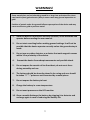
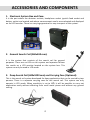
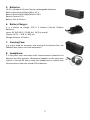
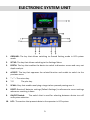
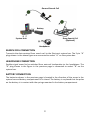
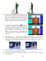
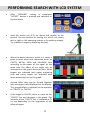
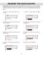
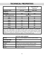
INDEX Accessories and Components ......................................................................... 4 Electronic System Unit ..................................................................................... 6 Assembly and Charging the Battery ................................................................ 7 Using the LCD Mode ........................................................................................ 9 What is Ground Setting and How It Is Done ................................................. 12 How Ground Setting Is Made ......................................................................... 13 Performing Search with LCD System ............................................................. 15 Reading the Oscilloscope ............................................................................... 17 Ferrous Metal Elimination Function .............................................................. 18 Getting and Analysis Report by Analyzing the Target .................................... 19 Detection of Target Depth ............................................................................. 19 Technical Properties ..................................................................................... 21 Accessories .................................................................................................... 22 1 WARNING! PLEASE DO NOT START ASSEMBLING OR USING BEFORE READING THE WARNINGS SECTION! 2 WARNINGS! Some metals that are buried under ground for a long time and rotten like sheet steel and tin (lead, galvanize etc.) May in some cases may give an impression as gold. Position of metals under the ground influence perception of the device and may cause an effect as gold or precious metal. 1. Since the device is electronic and very sensitive; never assemble and operate before reading the user manual. 2. Do not start searching before making ground settings. It will not be possible that the device operate correctly unless the ground setup is made. 3. Do not use any other detector or a device that emit magnetic waves within 10 m proximity of the device. 4. Prevent the device from abrupt movements and possible shock. 5. Do not expose the search coil to direct heat; do not exert force during assembly and use. 6. The battery should be decently placed in its casing and care should be taken “+” “-“ poles are not connected by a metal pieces. 7. Do not expose the battery to heat. 8. Charge the battery in room temperature. 9. Do not exert pressure on the LCD monitor. 10. Once a month discharge the battery by plugging it to detector and recharge again in case of enduring the battery life. 3 ACCESSORIES AND COMPONENTS 1. Electronic System Box and Case: It is the part where the detector sockets, headphone socket joystick feed socket and battery socket are located and where measurement results are evaluated and displayed on the LCD monitor. There is a carrying apparatus for easy transport of this system. 2. General Search Coil (360x440 mm): It is the system that consists of the search coil for general purposes. There are no LEDs on this system and operator follows the results on a LCD monitor located on the system box. This system can only be used in LCD mode. 3. Deep Search Coil (600x1000 mm) and Carrying Case (Optional): This is the search coil system developed for deep exploration that can be carried by two persons. There is a separate carrying case for this search coil. This system can only operate in LCD mode. When sensitivity is set to 60% it will be possible to carry out exploration easily without affecting from small metal pieces and without any ground setting. 4 5. Batteries: 14.8 V, 4 Ampere Lithium Polymer rechargeable batteries. Battery Operating Voltage (Min): 12 V Battery Operating Voltage (Max): 14.8 V Battery Current: 4 A Battery Life: 4-6 hours 6. Battery Charger: It is a device to charge 14.8 V 4 Ampere Lithium Polymer batteries. Input: AC 100-240 V / 50-60 Hz / 1A (City mains) Output: DC 12 – 16.8 V / 400 mA Charge duration: 10 hours 7. Carrying Case: It is a case used for transport and storing of the System box, the 360x440 mm Search coil and accessories. 8. Headphone: It is the piece that maintains vocal communication between the detector and the operator. Waterproof speaker on the electronic system is turned off when using the headphone to enable only the operator to hear the sound of the detector. 5 ELECTRONIC SYSTEM UNIT 1. GROUND: The key that allows switching to Ground Setting mode in LCD system mode. 2. SETUP: The key that allows switching to the Settings Menu. 3. DEPTH: The key that enables the device to switch to diameter screen and carry out depth analysis. 4. ACCEPT: The key that approves the related function and enable to switch to the previous menu. 5. “ – “ : The minus key. 6. “+”: 7. SCAN: A key that enables analyzing a target when pressed passing over it. 8. RESET: Resets all detector settings (Default Settings) in reference to recent settings whenever resetting is done. 9. ON/OFF Switch: The switch that is used for selecting between device turn off and system selection. The plus key. 10. LCD: The section that presents data to the operator in LCD system. 6 ASSEMBLY AND CHARGING THE BATTERY 1. CHARGING THE BATTERY: Remove the battery from the system box and connect to the charger. When battery is being charged red LED will lights and when the charging is done green LED will lights. If there is no battery attached to the charger or the attached battery is fully charged the green LED lights. After charging, disconnect the battery from the charger and place it into system box. The charging period required for a fully depleted battery to be fully charged is 7 hours. 2. ASSEMBLY: Search coil is taken off the carrying case and telescopic extension tube is inserted, piece Nr.1 into piece Nr.2 as shown in the diagram and tighten the sleeve. The search coil is dismounted from the extension tube when packing in the carrying case. Dismantling is carried out as the reverse of the process described above. CAUTION: Do not take apart the screws that connect the Connecting piece and Search coil. Take off only the telescopic tube without damaging cable coil and suitably store in the carrying case. 7 General Search Coil Battery System Unit Deep Search Coil (Optional) Headphone SEARCH COIL CONNECTION Transmits the data received from search coil to the Electronic system box. The 5 pin “A” plugs shown in the above figure are connected to socket “A” on the system box. HEADPHONE CONNECTION Enables signal sound to be switched from external loudspeaker to the headphone. The “B” plug shown in the figure in the previous page is connected to socket “B” on the system box. BATTERY CONNECTION The batteries shown in the previous page is located in the direction of the arrow in the system box and battery compartment lid is closed. The battery is so placed that the poles on the battery is in contact with the springs mounted in the battery compartment. 8 USING THE LCD MODE NOTE: The LCD system function of the device can only be used when 360x440mm search coil and 600x1000mm search coil is installed. Install the 360x440mm or 600x1000mm search coil to the system box as described in the “assembly” section. The device has two separate systems. One of these systems is the LED System, the other is LCD System. To switch the device to LCD System, the commutator switch is adjusted to LCD. After the device is switched on the operator makes the desired language selection by using “+” and “-“ keys and press “ACCEPT” button to finalize the language selection. When the device is on the LCD mode the screen system is enabled and the device detects the installed search coil and prepares for that search coil. If no search coil is installed on the device a warning is displayed on the screen. Coil and System Error Warnings: If there is an error in the search coil or in the system “SEARCH COIL FAULT” or “SYSTEM FAULT” warning lights blink at the bottom of the screen and a sound alarm is heard to warn the operator after the device is switched on. In this case the operator should switch off the device, check the connectors and witch on the device again. If the warning persists authorized service should be called. 9 Checking Battery Charge Level: The device switches to “Ground Adjustment” section after it detects the search coil. At the bottom of this section there is an area that indicates battery status and the operator detects battery status by referring to this area. If the battery is depleted or does not have adequate charge switch off the device and charge the batteries installing the charger. Adjustment of SOUND Level: “SETUP” button is pressed for adjusting the level of sound of the device in whatever mode is it in. The current adjusted sound level is displayed as % on the screen. Select the “SOUND” mode by pressing “+” and “-“ keys as described above. After this mode is selected press the “ACCEPT“ button, the sound indicator bar will turn from yellow into green. Adjust the sound level by pressing “+” and “-“ keys and press “ACCEPT” button. The green indicator bar turns back into yellow. Now the sound level is adjusted as you desired and you can switch to the previous mode by pressing “SETUP” button. Adjusting LIGHT Level: “SETUP” button is pressed for adjusting the level of light of the device in whatever mode is it in.The current adjusted light level is displayed as % on the screen. Select the “LIGHT” mode by pressing “+” and “-“ keys as described above. After this mode is selected press the “ACCEPT” button, the light indicator bar will turn from yellow into green. Adjust the light level by pressing “+” and “-“ keys and press “ACCEPT” button. The green indicator bar turns back into yellow. Now the light level is adjusted as you desired and you can switch to the previous mode by pressing “SETUP” button. 10 Adjustment of SENSITIVITY Level: “SETUP” button is pressed for adjusting the level of sound of the device in whatever mode is it in. The current adjusted sensitivity level is displayed as % on the screen. Select the “SENSITIVITY” mode by pressing “+” and “-“ keys as described above. After this mode is selected press the “ACCEPT“ button the sensitivity indicator bar will turn from yellow into green. Adjust the sensitivity level by pressing “+” and “-“ keys and press “ACCEPT” button. The green indicator bar turns back into yellow. Now the sensitivity level is adjusted as you desired and you can switch to the previous mode by pressing “SETUP” button. Adjustment of IRON Mode: “SETUP” button is pressed for switching the level of IRON mode of the device on and off in whatever mode is it in. The current IRON mode is displayed as open or closed. You may find more detailed information about the properties of this mode and how it is used in following sections. Using the RESET Button: When the device is in use some interference may occur due to the environment or unbalanced search coil movement. These interferences start to show on the screen and cause the device to give a sound alarm. Resetting can be done by pressing the “RESET” button on the system box. By resetting the effects of interference are eliminated. Resetting should not be done when the search coil is over the target! This will cause loss of depth, misinterpretation of received signal and the target become invisible to the device. Resetting procedure is carried out after the search coil is removed away from the target. 11 WHAT IS GROUND SETTING AND HOW IT IS DONE? In our country land formation and soil composition vary in relation to regions. In some regions the composition may vary frequently (Sand, lime, red earth with dense mineral content, rocky formation, etc.). These variations in soil composition mislead the detector and cause perception as metal or cavity. Therefore first we have to launch the soil characteristics of the region to the detector’s system. Launching these data will block all misleading effects that may come up from the ground; these will be perceived as misleading signals from the ground, and thus eliminated. Ground setting is one of the most important provisions of exploration. Therefore the operator should be a keen observer and should be able to detect variations in the ground. He has to observe soil compositions continuously to be able to make ground adjustment again in case misleading signals the device will perceive results from variations in soil composition. Ground setting is made for the device to recognize the soil and not to be affected by it. Thus the device is not affected from metal or cavity reflections of varying soil compositions. If ground setting is not properly done it will cause loss of depth and minerals to be evaluated as metals or cavities. Therefore ground settings should be made as correctly as possible. Considering the general condition of land formation in our country, a ground setting system is established that will eliminate ground effect on the device. 12 HOW GROUND SETTING IS MADE? When the device is switched on it starts with the “GROUND ADJUST” mode. Ground adjustment should be done before using the device for correct results. During exploration when soil composition has changed and when ground adjustment has to be done again switch to ground mode by pressing the “GROUND” button and re-adjust ground settings after checking existing settings. Ground Setting Phases 1. When the device is switched on in “LCD” mode, ground adjustment is displayed automatically. 2. Lift the search coil 40 cm above ground and press the “RESET” button. 3. When in ground mode the effect of ground on the device is displayed on the monitor as “Ground Effect”. This effect will change when ground adjustment is made. (NOTE: The search coil must be lifted 40 cm above the ground and the RESET button to be pressed in order to reset previous values, otherwise following results will not be reliable.) 4. Make sure that there are no metal objects or cavities in the ground where ground setting will be made. If ground setting could not be adjusted it will be repeated in a neighboring area. 5. The operator lifts the detector search coil “40 cm” above the ground and after pressing RESET lowers the search coil “3-5 cm” parallel to the ground. If the device receiving negative effects the operator lifts the detector and presses the “-“ button several times, if the effect is positive the operator presses the “+” button several times and presses reset button, then lowers the search coil to 3-5 cm form the ground. The procedure must be repeated until the ground effect is neutralized. The device is ground balanced when you do not get to hear any signal when lowering the search coil for exploring. After the effect is neutralized the operator raises the detector search coil 8-15 cm above the ground and switches to the explore mode by pressing the “ACCEPT” button. Stabilizing the detector 8-15 cm from the ground will give you reliable search results. 13 6. If there is no ground effect on the device there is no interaction on the bar that is indicated in the figure and “Ground Setting 100% Completed” expression is displayed. In this case the device is ready for exploring and you may switch to explore mode by pressing the “ACCEPT” button. 7. In case there is ground effect on the device an interaction is observed in the “GROUND ADJUST” bars that are indicated in the figure. To eliminate this effect press “-“ button for “-“ effect and press “+” button for “+” effect. Press “-“ or “+” buttons until this effect is eliminated and “Ground Setting 100% Completed” expression is displayed. 8. After pressing “+” or “-“ buttons lift the search coil 40 cm above ground and press the “RESET” button and observe the ground effect by holding the search coil 3-5 cm above ground, if ground effect persists try to eliminate this effect by pressing “+” or “-“ buttons. 9. If we are not able to eliminate the ground effect decrease the sensitivity level one step and repeat the above defined operation. 10. After the ground effect is eliminated you may press the “ACCEPT” button and switch to Explore Mode. 14 PERFORMING SEARCH WITH LCD SYSTEM After “GROUND” setting is completed “ACCEPT” button is pressed and switched to Explore Mode. Hold the search coil 8-15 cm above and parallel to the ground. You can explore by moving the search coil slowly with a right to left sweeping motion or by walking straight. Try to detect a target by exploring this way. When the device detects a metal or a cavity it gives a sound alarm and interaction occur on CAVITY, METAL, IRON and VALUABLE bars according to the power of the signal. At the same time the effect of the target can be monitored on the graph above the bars. Metal targets are indicated with upper projecting lines and cavity targets are indicated with lower projecting lines on this graph. Ground effect that may be formed together with the target is also displayed on the display. This ground effect is indicated to the operator as “CAVITY” or “METAL” If the target is a CAVITY, there is a raise on the “CAVITY” bar and decrease in the graph. The intensity of the “CAVITY” bar is indicated as % on top depending on the magnitude of the effect of target. 15 If the target is valuable metal, there is a raise both on the “METAL” and ”VALUABLE” that is expressed in % depending on the magnitude of the effect. The effect of metal can be monitored in the graph on top of the bars. If the target is worthless metal there is a raise both on the “METAL” “IRON” that is expressed in % depending on the magnitude of the effect. When an alarm is received from the device over any point; the device is taken away from the target and reset in an area where no signal is received and the search coil is passed over the same target again. If there is increase in the “CAVITY” bar, our target is a cavity. If there is increase in the “METAL” and “VALUABLE” or “IRON” bar, our target is a metal. If required the “RESET” button is pressed and search coil is passed over the target once more. This last operation is done to be sure about the result. 16 READING THE OSCILLOSCOPE Oscilloscope draws plan view of an underground target. It helps us to pre-understanding the shape, quantity and depth of the target. Also it is a very important system that allows knowing that the source signal is a metal or a mineral source by reading the oscilloscope right. 1- Target is a small metal and close to surface; 5- Target is a large metal and deep; 2- Target is a couple of small metals and close to surface; 6- Target is a large metal and deeper underground; 3- Target is a couple of small metals and slightly deep; 7- Target is a cavity and very close to surface; 4- Target is a large metal and close to surface; 8- Target is a cavity and deep; 17 9- Target is a cavity and deeper underground; 11- If the oscilloscope line draws a straight line close to center line, it points that the ground is a high-mineral soil. So, the ground balance needed to be recalibrated. 10- Target is a metal inside of a cavity; or If the signal line increases very sharp and decreases with same velocity there is no need to calculate depth. Because, this shows that the target is very close the surface. Oscilloscope never draws a straight line while it receives signals from true target, it always draws sinuous lines. Oscilloscope line is closer the center line when the target is deep and line is away from the center line when the target is close. Ferrous Metal Elimination Function: The device can enable to filter the worthless metals by the device and warn the operator if desired. For this operation “IRON” mode should be off. To switch off this mode press “SETUP” button when in explore or ground modes. Select the “IRON” mode by pressing the “+” key. After selecting this mode press the “ACCEPT” button. Place the frame that turns from yellow to into green on “OFF” and press the “ACCEPT” button again. After this operation press “SETUP” button to switch to the previous mode. Following this step the device will filter worthless metals. To be able to detect worthless metals again this mode should be switched back to “ON” mode by repeating above mentioned operation. 18 Getting and Analysis report by Analyzing the Target: To get an analysis report by analyzing the detected target during exploration: Press the “RESET” button by removing the search coil off the target after the target is detected. Press and hold the “SCAN” button when passing over the target again slowly. At that moment the device analyzes the target. Release the “SCAN” button after you pass overt the target. After this operation the device presents the “ANALYSIS REPORT” to the operator. Type of the metal, magnitude of the target and the ratios of other environmental effects are received. Detection of Target Depth: For detecting target depth during exploring: Press the “DEPTH” key when in explore mode after the target is detected. First the dimensions of the target should be determined in depth mode. This operation is explained in detail with operator help menu. To enter the help menu form a yellow frame around the “HELP” window by using “+” and “ “ keys. Press the “ACCEPT” button after forming this frame. In this menu it is explained to the in detail how to determine the dimensions of the target. To enter the determined width dimension place the yellow frame on “Width” by using “+” and “-“ keys. Press the “ACCEPT” button to convert the yellow frame to green. 19 Enter the “Width” value by using “+” and “-“ keys. Press the “ACCEPT” button after entering the width value and convert the frame into yellow. To enter the determined length dimension place the yellow frame on “Length” by using “+” and “-“ keys. Press the “ACCEPT” button to convert the yellow frame to green. Enter the “Length” value by using “+” and “-“ keys. Press the “ACCEPT” button after entering the length value. Press the “SCAN “ button after this operation and pass over the target again and release the “SCAN” button After this operation the device presents an “Analysis Report” that indicates whether the target is METAL or CAVITY, entered dimension values and environmental effects. Press the “ACCEPT” button to leave this report. Switched back to Depth mode and switched to explore mode by pressing the “DEPTH” button. 20 TECHNICAL PROPERTIES General Search Coil Deep Search Coil (Optional) 360 x 440 600 x 1000 Dimensions (mm) Frequency 12.5 kHz (VLF) Used Mode LCD Target Diameter (cm) LCD Depth (cm) 5x5 56 56 10x10 75 96 20x20 110 154 30x30 132 185 40x40 154 226 50x50 176 260 60x60 189 292 The values stated above aren’t generated values; they are gathered by trying new metals. As the dimensions of the metals increase, there is an increase in the depth as seen in the ratios stated in the table. If metals remain under the ground for a long time, in pace of that time they establish a magnetic area and these magnetic areas radiates as if there are transmitters. By this means, the receiver of the research antenna ensures detection of the same target in 3-4 times deeper areas. BATTERY AND CHARGER Battery 16.8 V, 3.3 A Rechargeable Lithium Polymer Battery Operating voltage 12 V – 16.8 V Battery current 3.3 A Charger 16.8 v 500 mA Lithium Polymer Battery Charger Input AC 100-240 v / 50-60 Hz / 180 mA (city mains) Output DC 16.8 V / 500 mA 21 ACCESSORIES Condura Plastic totebag for the whole hardware. Headphones Double zippered Condura plastic carriage bag reinforced for deep search coil. (Optional) Lithium Polymer Battery Universal AC charger 100 - 240 Volt, 50 and 60 Hz System box leather totebag. Automotive charger (Optional) Warranty Period: 2 Years Note: Battery, bags, headphones and chargers are not covered by warranty. 22


![Manual de instalação Protecção frontal para Stûv 16 [pt]](http://vs1.manualzilla.com/store/data/006055490_1-b2af17d6abb699312cff36601c0c9cba-150x150.png)