1
ALLIANCE SERIES
OWNER'S MANUAL
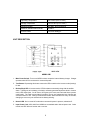
TABLE OF CONTENTS
PAGE
1. INTRODUCTION ……………………………………………………………....
1
2. RECEIVING INSPECTION ………………………………………………….
1
3. WARRANTY REGISTRATION ……………………………………………...
1
4. IMPORTANT SAFETY INSTRUCTIONS …………………………………...
1
5. ELECTRICAL SPECIFICATIONS ……………………………………………
3
6. TYPICAL RUN TIME VERSUS LOAD ………………………………………
5
7. PHYSICAL SPECIFICATIONS ………………………………………………
5
8. UNIT DESCRIPTION …………………………………………………………
6
9. INSTALLATION AND TEST …………………………………………………
7
10. OPERATION …………………………………………………………………...
8
11. SYSTEM BATTERIES ……………………………………………………...…
8
12. BATTERY/SYSTEM CHECKOUT …………………………………………...
9
13. UPS MONITORING CONFIGURATIONS …………………………………..
9
14. UPS DB9 PIN OUT …………………………………………………………….
9
15. SERVICE ………………………………………………………………………..
10
16. UPS PROBLEM CHART ………………………………………………………
10
17. POLICY AND INSTRUCTIONS FOR RETURN OF PRODUCT ………….
11
INTRODUCTION
The MINUTEMAN ALLIANCE Series Uninterruptible Power Supply (UPS) has been designed to be
maintenance-free, and to provide years of excellent service. It will provide superior power
protection for personal computers, telephone systems and other critical electronic equipment
against all commercial power anomalies. Output waveform is a synchronized, simulated sinewave.
Both LED and audible alarms indicate UPS and commercial power status at all times. Other
features include:
Light weight and small footprint.
Quiet operation.
Excellent non-linear current capability.
LAN communications port (except A300).
Automatic UPS test at turn-on.
Site wiring fault indication (120 VAC models).
Low voltage boost to facilitate low commercial voltage operation without battery
utilization (except A300/A425).
Transfer voltage adjustment switches (except A300/A425).
RECEIVING INSPECTION
SAVE THE PACKING MATERIALS!
Remove and inspect the unit for shipping damage. If damage is found, immediately notify the
carrier and your dealer. If no damage is found, save both the shipping container and the packing
foam in case of a later need to return the unit to the factory, or ship it to another location.
WARRANTY REGISTRATION
Complete the warranty registration card provided in the back of this manual and mail it within ten
days of receipt to register your warranty. Failure to register your warranty renders it non-valid.
IMPORTANT SAFETY INSTRUCTIONS
SAVE THESE INSTRUCTIONS
Read this manual carefully before operating the UPS. All instructions should be followed
during installation and maintenance of the UPS and batteries.
1
These UPS units are intended for use in a temperature-controlled, indoor area free of
conductive contaminants. Select a location, which will provide good air circulation for the
UPS at all, times. Avoid locations near heating devices, water or excessive humidity, or
where unit is exposed to direct sunlight. Route power cords so they cannot be walked on
or damaged.
CAUTION -- The UPS uses batteries for generating AC voltages, so output receptacles
may be electrically hot even when the UPS is not connected to commercial power. Trained
service personnel should perform all repairs, since an electrical shock hazard exists.
CAUTION -- Do not remove the cover -- there are no user-serviceable parts inside.
CAUTION -- To prevent electrical shock, the 3-wire plug provides earth ground for the UPS
chassis. Plug the UPS into a 3-wire grounding type, commercial receptacle with the
grounding conductor connected to earth ground at the service equipment. Removal of the
ground pin from the plug or use of a 3-wire-to-2-wire adapter will defeat this safety feature
and may result in a shock hazard. Additionally, if the plug is removed to simulate a power
failure (not recommended), do not touch the plug conductors or the chassis while the plug
is removed. On 120-volt models, improperly connected power will indicate a Site Wiring
Fault.
CAUTION -- Do not allow water or any foreign object to enter the UPS. In case this occurs,
immediately turn the unit power switch off and unplug the MINUTEMAN from the
commercial receptacle.
Servicing of batteries should be performed or supervised by personnel knowledgeable of
batteries and the required precautions. Keep unauthorized personnel away from the
batteries.
When replacing UPS batteries, use the same number of sealed lead-calcium rechargeable
batteries with the same voltage and ampere-hour ratings as those in the UPS. These
batteries have pressure operated safety vents.
CAUTION -- Do not dispose of batteries in a fire. They may explode.
CAUTION -- Do not open or mutilate batteries. Release electrolyte is harmful to the skin
and eyes and may be toxic.
CAUTION -- Although battery system voltages are only 12 VDC, 24 VDC and 36 VDC, the
battery system can still present a risk. The current capability of a battery is sufficient to
burn wire or tools very rapidly, producing molten metal. Observe these precautions when
working on batteries:
1. Turn the UPS off and disconnect it form the wall outlet prior to connecting or
disconnecting battery terminals;
2. Remove watches, rings or other metal objects;
3. Use tools with insulated handles;
4. Wear protective gloves and eyewear;
5. Do not lay tools or other metal parts on top of batteries.
2
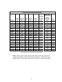
ELECTRICAL SPECIFICATIONS
MAX. HEAT
DISSIPATION
BATTERY
RATED
OUTPUT
FREQ
INPUT
OUTPUT
SYSTEM
MODEL #
VA
WATTS
Hz
VAC/A
VAC/A
A300
300
190
60
120/2.6
A300/2
300
190
50
A425
425
275
A425/2
425
A500
BTU/Hr
AC
VDC
INVERTER
MODE
MODE
120/2.5
12
160
10
220/1.5
220/1.4
12
160
10
60
120/3.6
120/3.5
12
235
10
275
50
220/2.0
220/1.9
12
235
10
500
325
60
120/4.3
120/4.2
12
275
65*
A500/2
500
325
50
220/2.6
220/2.3
12
275
65*
A750
750
500
60
120/6.5
120/6.3
24
425
105*
A750/2
750
500
50
220/3.4
220/3.4
24
425
105*
A900
900
630
60
120/8.8
120/7.5
24
540
130*
A900/2
900
630
50
220/4.2
220/4.1
24
540
130*
A1250
1250
900
60
120/12.1
120/10.4
24
770
185*
A1250/2
1250
900
50
220/5.8
220/5.7
24
770
185*
A2000
1440
1400
60
120/12
120/12
36
1200
300*
A2000-41
1900
1400
60
120/16
120/15.8
36
1200
300*
A2000-43
1900
1400
60
120/16
120/15.8
36
1200
300*
A2000-44
2000
1400
60
120/20
120/16.7
36
1200
300*
A2000/2
2000
1400
50
220/10
220/9.1
36
1200
300*
* With maximum boost and maximum charge current.
NOTE: 220VAC, 50 Hz models supply an output voltage of 220VAC, making them
compatible with 220VAC, 230VAC and 240VAC utility systems. UPS inverter output
supplies 225 VAC. Other output voltages can be factory-set on a special-order basis.
3
Input Voltage (AC Mode Function)
120 VAC Models
95-135 VAC (w/ boost)
102-135 VAC (w/o boost)
175-260 VAC (w/ boost)
220 VAC Models
190-260 VAC (w/o boost)
Boost Capability (AC Mode Function)
+ 12 %
5VAC per SW, (120VAC models)
Transfer Voltage Adjustment
10VAC per SW (220VAC models)
Transfer Time
2 msec typical
Input Frequency Deviation for Synchronization
± 10 %
Inrush Current
1.5x rated
Surge Protection
3 way, meets IEEE STD. 587
RFI/EMI Filtering
Both Common and Normal Modes
Inverter mode (Backup Operation)
Waveform
Synchronized Simulated
Sinewave Approximation
Crest Factor (Non-Linear Load)
3:1
Overload Capacity (50 msec Maximum)
3x rated
Voltage Regulation
± 5%
Frequency Regulation
± 1%
DC-to-AC Efficiency (Full Load)
75%
Overload/Short Circuit Protection
Electronic and Fused
Discharged Battery Recharge Time
8 hours (95% of full charge)
Run Time
See Chart
4
TYPICAL RUN TIME vs. TYPICAL COMPUTER LOAD
Computer
Load
A300
A425
A500
A750
A900
A1250
A2000
100VA
30m
38m
68m
86m
122m
133m
379m
150VA
19m
22m
38m
48m
72m
79m
211m
200VA
12m
15m
25m
32m
50m
54m
139m
250VA
8m
11m
19m
24m
37m
41m
101m
300VA
5m
8m
14m
18m
29m
32m
78m
425VA
---
5m
9m
11m
19m
20m
47m
500VA
---
---
6m
9m
15m
16m
37m
600VA
---
---
---
7m
12m
13m
28m
700VA
---
---
---
6m
10m
11m
23m
750VA
---
---
---
5m
9m
10m
21m
800VA
---
---
---
---
8m
9m
19m
900VA
---
---
---
---
7m
8m
16m
1000VA
---
---
---
---
---
7m
14m
1100VA
---
---
---
---
---
6m
12m
1250VA
---
---
---
---
---
5m
10m
1400VA
---
---
---
---
---
---
8m
1600VA
---
---
---
---
---
---
7m
1800VA
---
---
---
---
---
---
6m
2000VA
---
---
---
---
---
---
5m
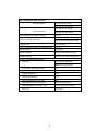
PHYSICAL SPECIFICATIONS
Dimensions
Model
Net Wt.
(lbs.)
Shipping Wt.
(lbs.)
(L x W x H) (inches)
A300
15
18
13.5 x 3.3 x 6
A425
15
18
13.5 x 3.3 x 6
A500
23
25
13 x 4.6 x 6.6
A750
29
30
16 x 4.6 x 6.6
A900
46.5
49.6
18.4 x 6.3 x 9.8
A1250
49.2
52.3
18.4 x 6.3 x 9.8
A2000
70.8
77.9
19.9 x 6.3 x 9.9
5
Operating Temperature
0ºC to 40ºC (32ºF to 104ºF)
Storage Temperature
-15ºC to 40ºC (5ºF to 104ºF)
Relative Humidity
95% Max., Non-Condensing
Maximum Altitude without Derate
15,000 Ft.
Acoustic Noise
Less than 40dB @ 3'
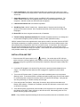
UNIT DESCRIPTION
1. Main Power Switch: Turns on all UPS functions except the internal battery charger. Charger
operates when UPS is connected to commercial power.
2. Test Button: Depressing this button causes the UPS to switch to the Inverter mode (backup)
for test.
3. Backup/Fault LED: In Inverter mode, LED illuminates momentarily along with the audible
alarm. If UPS goes to low battery, overload or software-generated shutdown while in Inverter
mode, UPS shuts down. On AC return, UPS goes to AC mode, and Fault and Alarm operate
continuously. The Fault is reset either by pressing Test or any subsequent loss of power and
successful return to AC. During normal Inverter mode, alarm sounds once every 15 seconds,
changing to once every two seconds at low battery warning.
4. Normal LED: On in normal AC mode when commercial power is present; otherwise off.
5. Input Power Cord: A300, A425 and A2000 use a standard strain relieved power cord. Other
models use IEC 320 male socket and a cord set.
6
6. Input Fuse/Breaker: A300, A425, A900 and A1250 use a separate fuse holder for the input
fuse; A2000 models use an input breaker. Other models have the input fuse located in the IEC
320 socket.
7. Output Receptacles: All 120VAC models use NEMA 5-15R receptacles (standard). The
A2000 120VAC model has one receptacle position, which can be converted, to a locking
receptacle. 220VAC models use IEC 320 female receptacles.
8. LAN Communications Port: All models except A300.
9. Site Wiring Fault: 120VAC models only. Indicator warns of improper service wiring, lost
ground or hot/ neutral reversed. Have a qualified electrician correct the service wiring if this
lamp lights.
10. Boost LED: On when unit goes to boost mode; off otherwise.
11. Transfer Voltage Adjustment Switches: Each switch decreases brownout, over-voltage and
boost transfer voltages by 5VAC (120VAC models) or 8VAC (220VAC models).
220VAC models: Each unit is supplied with 2 output power cords for connection from the UPS IEC
320 female receptacles to computer equipment. An input line cord is not provided because of the
many different plug configurations used in the countries served. In most cases, the existing input
line cord for the computer can be used for connection to the UPS input. If an input line cord is
needed, these are available through your supplier. Units ordered from the factory with an input line
cord provided contain only 1 output power cord.
INSTALLATION AND TEST
1. Ensure that the UPS power switch is off ("
" position). On models with an IEC 320 input
socket, insert the cord-set supplied or the computer cord-set into the UPS socket, then plug the
UPS power plug into a grounded commercial power receptacle, with proper supply voltage and
frequency.
2. Leave the UPS plugged in, but turned off for two hours to permit the internal batteries to recharge. The charger operates when the UPS is plugged in, regardless of power switch
position.
3. Turn on the UPS power switch ("|" position) and it will immediately power up in the Inverter
(Backup) mode. If commercial power is available and within proper range, the UPS will transfer
to commercial power in about four seconds, and the AC Normal LED will light. Verify that the
site wiring fault lamp (on 120VAC models) does not light.
4. Press and hold the Test Button. After about 30 seconds, there will be a short Alarm and
Backup LED indication. Release the Test Button, and the UPS will return to normal AC mode
(in about four seconds).
5. Verify that the power requirements (VA and Watts) of the equipment to be protected are within
the capacity of the UPS. Plug in and turn on the various loads. Momentarily press the Test
Button and verify proper UPS operation.
NOTE: If any condition experienced during the above test procedure was not as described, refer to
7
the UPS problem chart in the back of this manual.
OPERATION
The UPS loads may be controlled by the UPS power switch. Since the UPS powers up in the
Inverter mode, a functional test is provided every time it is turned on (or the TEST Button is
pushed). The battery charger operates with the power switch on or off.
If a low voltage condition (brownout), power outage or over-voltage occurs, the UPS will switch to
the Inverter mode, and the AC Normal LED will go out. The Backup LED and Alarm will operate
briefly after about 25 seconds, and then every 15 seconds. For long duration power outages, a
Low Battery Warning is provided about two minutes prior to low battery shutdown. The LED and
Alarm will operate every two seconds. At low battery shutdown the UPS will shut off automatically
to protect the internal batteries form excessive discharge. All LED's, alarm and output power will be
turned off. When commercial power returns, the UPS will return to the AC Normal mode; the Fault
LED and Alarm will operate continuously. Press the Test Button to effect an inverter test and
silence the alarm.
During normal AC mode function, the UPS will quietly protect the load from power surges, voltage
spikes and noise interference. Commercial power outages are usually of a short duration; thus
sounding of the alarm is delayed so as not to be a nuisance.
If the low voltage condition above can be corrected by the boost winding in all models except A300
and A425, the Boost LED will light, signifying the Boost mode is operative and the output voltage
has been corrected.
SYSTEM BATTERIES
The internal batteries used in the MINUTEMAN ALLIANCE UPS UNITS are sealed maintenancefree, lead-acid batteries with electrolyte totally absorbed in the plates and separator material. For
maximum battery like, temperature should be kept as cool as practical indoors, and at proper trickle
charge voltage. Expected battery life is 3 to 6 years at 85ºF. For optimum performance, batteries
should be replaced after about 3 years. Replacement batteries can be purchased from Para
Systems or from your local distributor or dealer. If the UPS is to be stored, allow the batteries to
fully charge for 24 hours; then store in a cool, dry location. For extended storage, recharge the
UPS batteries for 24 hours every 4 months.
When the batteries are replaced, provide the used batteries to recycler for proper disposal and
reclamation of the lead.
BATTERY/SYSTEM CHECKOUT
To verify proper system function and battery condition, the user is encouraged to engage the test
switch periodically. Normal indications as specified should be observed. If the system goes
immediately to the low battery warning mode, the batteries should be replaced.
8
UPS MONITORING CONFIGURATIONS
All models except A300 provide a UPS monitoring capability which will allow direct interface with
many different computer operating systems. This capability permits an unattended, orderly
shutdown of the computer system when commercial power is lost for a long period. Some
configurations also provide for a shut down of the UPS after the computer has been shut down,
thereby conserving UPS battery capability.
Para Systems also offers its own software package, which functions with Novell, Unix-based, OS/2,
Windows and Macintosh operating systems. This package offers many advantages over existing
UPS monitoring packages.
Finally, for systems which do not have UPS interface capabilities, user software can be written to
read UPS status and provide for system shut down. Software specialists should contact Para
Systems, Inc. for more information. The standard UPS DB9 PIN out is provided below for your
information.
COMMUNICATIONS PORT
The communications port on the back of the UPS (DB9 Female Connector labeled "Signal") can be
connected by a cable to a computer to provide the UPS monitoring capability described above.
Following are the pin connections of this connector.
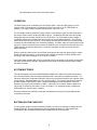
UPS DB9 PIN OUT
PIN 1
N.C.
PIN 2
UPS simulates a relay closing (open collector transistor) between Pins 2 and 4
when it switches to Inverter mode.
PIN 3
Not used
PIN 4
Common ground return (for Pins 2, 5, 6 and 8).
PIN 5
UPS simulates a relay closing (open collector transistor) between Pins 5 and 4
at low battery warning.
PIN 6
User sends a RS232 high level (9-12VDC) to turn off the UPS (works only
during Inverter operation). UPS returns to AC mode when commercial power is
restored.
PIN 7
Common with Pin 4.
PIN 8
A500 and larger units: When this pin is shorted to ground, UPS output turns off.
Output returns when commercial power is available and the short is removed.
On units smaller than the A500, this pin has no connection.
PIN 9
Reserved.
9
SERVICE
If any problem is encountered with your MINUTEMAN ALLIANCE UPS, contact your supplier or
Para Systems customer service department. Prior to calling, please write down and be prepared to
discuss UPS status indications and if the UPS supplies power in any mode. Following is a guide to
assist you in locating some common problems.
Do not remove the UPS cover or attempt any service. There are no user-serviceable components
inside. Unauthorized service will void the warranty.
Fuse replacement and breaker reset (A200) are UPS owner responsibilities. Please do no return a
unit for service before verifying that that the fuse is good or the breaker is properly set.
UPS PROBLEM CHART
PROBLEM
POSSIBLE CAUSE
ACTION TO TAKE
When main power switch is
turned on, UPS comes on,
but does not go to the AC
Normal Mode.
Input fuse blown (breaker
tripped on A2000).
When main power switch is
turned on, UPS comes on,
goes to AC Normal mode;
Fault LED and Alarm
operate continuously.
UPS batteries are
Low/Weak
Turn UPS off and allow
batteries to recharge.
UPS is overloaded.
Check connected loads and
remove least critical item.
Backup time is considerably
less than expected; battery
charge condition is
unknown.
Load is greater than
estimated.
Check and verify connected
load.
No commercial power at
wall receptacle, or
commercial voltage is too
low or too high.
Batteries are not fully
charged or weak.
Check fuses and replace if
blown (see below). Reset
A2000 breaker.
Verify proper available
commercial voltage.
Recharge batteries for 8
hours and repeat backup
test.
Backup time is considerably
less than expected at the
end of a battery recharge
cycle (8 hours), and load is
verified.
Charger has failed, or
batteries are bad.
Call Para Systems for
service.
Site wiring fault lamp lights
Improper service wiring.
Have a qualified electrician
correct the service wiring.
10
FUSE REPLACEMENT (All Models except A2000)
A300, A300/2, A425, A425/2, A900 and A1250 models: Turn off the UPS and unplug the power
cord from the wall receptacle before removing the fuse cap. Remove and inspect the fuse and
replace, if blown.
Other models: turn off the UPS and unplug the power cord plug from the UPS IEC 320 socket.
Locate the fuse drawer opening and insert a flat-blade screwdriver into the opening, pry the drawer
outward and remove it from the IEC 320 socket. Inspect the active fuse and replace, if blown.
NOTE: Replacement fuses can be obtained from Para Systems or any electronic parts distributor
who stocks Bussman or Littlefuse fuses.
POLICY AND INSTRUCTION
FOR RETURN OF PRODUCT TO PARA SYSTEMS
Call Technical Support if you experience any problems with MINUTEMAN ALLIANCE Units.
1. If you wish to file a Platinum Protection Plan claim, request a claims packet from the
Technical Support Representative.
2. If a UPS unit must be returned to Para Systems for any other reason:
a. Describe the problem or reason for the return and you will be given a Return Material
Authorization Number (RMA #). This number must be placed on the shipping carton,
preferably on the return shipping label. The RMA # on the carton will ensure prompt
handling when received at Para Systems, Inc.
b. Pack the UPS for shipment in the original carton and foam. Other packaging methods
can result in damage to the UPS.
c.
Be sure to enclose the name and telephone number of the person who can authorize
repair charges. Also, include the address for product return.
d. Send the UPS freight prepaid to Para Systems headquarters. C.O.D. shipments will
not be accepted.
e. If repair is Para Systems' responsibility, per the warranty statement, there will be no
repair charge. The UPS will be repaired and returned freight prepaid, provided the
UPS was returned in the original shipping carton and foam. If other packing methods
used result in shipping damage, this repair will be at your expense. If the packaging is
not deemed usable for UPS return, there will be a charge for the cost of a new box and
foam.
f.
If UPS repair is not Para Systems' responsibility, you will be advised of the estimated
repair charges by telephone for your authorization. Should you choose not to have the
UPS repaired, there will be a repair estimate charge of $40. The UPS will be returned
C.O.D. for either the repair amount or estimate plus shipping and handling.
11
NOTE: Units returned for repair are found to have no function problem other than a blown,
replaceable input fuse, tripped, re-settable input breaker (a2000) or discharged batteries
will incur charges as stated in the above paragraph, even if these units are under warranty.
PARA SYSTEMS, INC.
1455 LeMay, Carrollton, TX 75006
Tel: (972) 446-7363
Fax: (972) 446-9011
LIMITED PRODUCT WARRANTY
PARA SYSTEMS, INC. (PARA SYSTEMS) warrants that this product will be free from defective material and
workmanship for a period of two years from the date of the original retail purchase by the end user provided
that the warranty registrations card is completed and returned PARA SYSTEMS within ten (10) days of
purchase. PARA SYSTEMS or its designated representative will repair, or at PARA SYSTEMS' option,
replace any product that has been returned by the purchaser and is confirmed by PARA SYSTEMS to be
defective.
This warranty shall be null and void if this product has been altered, opened without authorization, misused or
damaged by accident, misapplication, abuse, fire, flood or other disaster.
PARA SYSTEMS SHALL NOT BE LIABLE FOR DIRECT, INDIRECT, INCIDENTAL, CONSEQUENTIAL, OR
OTHER TYPES OR DAMAGES RESULTING FROM THE USE OF THIS PRODUCT OTHER THAN THE
LIABILITY STATED ABOVE. THIS WARRANTY IS IN LIEU OF ANY OTHER WARRANTIES EXPRESSED
OR IMPLIED, INCLUDING BUT NOT LIMITED TO, THE IMPLIED WARRANTIES OF MECHANTABILITY OR
FITNESS FOR A PARTICULAR PURPOSE.
MINUTEMAN PLATIMUM PROTECTION PLAN
LIMITED WARRANTY
In addition to the Product Warranty stated above, Para Systems, Inc. also warrants to the original purchaser
of the Minuteman products that all equipment connected to and powered by the UPS and registered under the
Minuteman Platinum Protection Plan shall be protected from damage caused by AC power surges, subject to
the following terms and conditions. Para Systems or its designated representative will, at Para Systems'
option, repair or replace any equipment so damaged, provided the cost of repair or replacement of the
equipment does not exceed twenty-five thousand dollars ($25,000).
TERMS AND CONDITIONS
1.
The UPS and connected equipment must be properly installed per the UPS Owner's Manual and in
compliance with all applicable electrical and safety code. Extension cords and power adapters are not to
be used.
2.
This warranty applies only to the original end user purchaser, who must register the UPS and connected
equipment within then (10) days of receipt.
3.
This warranty gives the purchaser specific legal rights, and the purchaser may also have other unspecified
rights which may vary from state to state.
4.
A finding will be issued by Para Systems within sixty (60) days or receipt of the affected Minuteman
unit/units and all documentation contained in the Minuteman Platinum Protection Plan Claims Packet. A
notice of the finding will be provided to the purchaser.
5.
This warranty does not cover: a.) any damage to any connected equipment resulting from any cause other
than AC power surge, as defined by IEEE Standard 587, which was transmitted through the UPS to the
connected equipment; b.) loss of data, software, business profits, claims by third parties and other
incidental damages even if Para Systems is advised of the possibility of such damages in advance.
6.
This warranty shall be null and void if the Minuteman product is altered, opened without authorization,
misused or damaged by accident, misapplication, abuse, fire, flood or other disaster.
PLEASE KEEP THIS DOCUMENT FOR YOUR RECORDS
12
Model # _______________________ Date Purchased __________________________
UPS PRODUCT AND MINUTEMAN PLATINUM PROTECTION PLAN LIMITED
WARRANTY REGISTRATION
UPS Model # _________________________ Serial # ___________________________
Date Purchased __________________________
Dealer's Name ___________________________________________________________
City/State ___________________________________ Zip ________________________
Your Name __________________________________ Tel. ________________________
Company Name (if applicable) _______________________________________________
Address ________________________________________________________________
City/State __________________________________ Zip __________________________
CONNECTED EQUIPMENT (Necessary for Platinum Protection)
1. MFG. _______________________ Model # ____________________ Serial # ________________
2. MFG. _______________________ Model # ____________________ Serial # ________________
3. MFG. _______________________ Model # ____________________ Serial # ________________
4. MFG. _______________________ Model # ____________________ Serial # ________________
To be valid, this registration must be returned within ten (10) days after purchase of equipment to Para Systems, Inc.
13