1
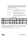
Installation, Operation and Maintenance
Bulletin OM49
Revision G
Type ES49( )
4.9-Meter ESA
4.9-Meter Earth Station Antenna
Notice
The installation, maintenance, or removal of antenna systems requires qualified, experienced personnel. Andrew installation instructions have been written for such personnel. Antenna systems should be inspected by qualified personnel to
verify proper installation, maintenance and condition of equipment.
Andrew Corporation disclaims any liability or responsibility for the results of improper or unsafe installation and maintenance practices.
All designs, specifications, and availabilities of products and services presented in this manual are subject to change
without notice.
Andrew Corporation
10500 West 153rd Street
Orland Park, IL U.S.A. 60462
Telephone: 708-349-3300
FAX (U.S.A.): 1-800-349-5444
Internet: http://www.andrew.com
Customer Service, 24 hours: U.S.A. • Canada • Mexico: 1-800-255-1479
U.K.: 0800 250055 • Republic of Ireland: 1 800 535358
12/03
Other Europe: +44 1592 782612
Copyright © 2003 by Andrew Corporation
Table of Contents
Introduction
Introduction. . . . . . . . . . . . . . . . . . . . . . . . . . . . . . . . . . . . . . . . . . . . . . . . . . . . . . . . . . . . . . . . . . . . . . . . 3
Proprietary Data . . . . . . . . . . . . . . . . . . . . . . . . . . . . . . . . . . . . . . . . . . . . . . . . . . . . . . . . . . . . . . . . 4
Information and Assistance. . . . . . . . . . . . . . . . . . . . . . . . . . . . . . . . . . . . . . . . . . . . . . . . . . . . . . . . 4
Notice . . . . . . . . . . . . . . . . . . . . . . . . . . . . . . . . . . . . . . . . . . . . . . . . . . . . . . . . . . . . . . . . . . . . . . . . 4
Technical Assistance . . . . . . . . . . . . . . . . . . . . . . . . . . . . . . . . . . . . . . . . . . . . . . . . . . . . . . . . . . . . 4
How to Use This Manual
Overview . . . . . . . . . . . . . . . . . . . . . . . . . . . . . . . . . . . . . . . . . . . . . . . . . . . . . . . . . . . . . . . . . . . . . . . . . . 5
Content . . . . . . . . . . . . . . . . . . . . . . . . . . . . . . . . . . . . . . . . . . . . . . . . . . . . . . . . . . . . . . . . . . . . . . . 5
Getting Started
Overview . . . . . . . . . . . . . . . . . . . . . . . . . . . . . . . . . . . . . . . . . . . . . . . . . . . . . . . . . . . . . . . . . . . . . . . . . . 6
Warnings . . . . . . . . . . . . . . . . . . . . . . . . . . . . . . . . . . . . . . . . . . . . . . . . . . . . . . . . . . . . . . . . . . . . . . 6
Recommended Tools . . . . . . . . . . . . . . . . . . . . . . . . . . . . . . . . . . . . . . . . . . . . . . . . . . . . . . . . . . . . 7
Parts Verification . . . . . . . . . . . . . . . . . . . . . . . . . . . . . . . . . . . . . . . . . . . . . . . . . . . . . . . . . . . . . . . . 8
Reporting Equipment Loss or Damage . . . . . . . . . . . . . . . . . . . . . . . . . . . . . . . . . . . . . . . . . . . . . . 8
Reporting Visible Loss or Damage. . . . . . . . . . . . . . . . . . . . . . . . . . . . . . . . . . . . . . . . . . . . . . . . . . 8
Reporting Concealed Damage. . . . . . . . . . . . . . . . . . . . . . . . . . . . . . . . . . . . . . . . . . . . . . . . . . . . . . 8
Inventory Equipment Received . . . . . . . . . . . . . . . . . . . . . . . . . . . . . . . . . . . . . . . . . . . . . . . . . . . . 8
Returning Equipment . . . . . . . . . . . . . . . . . . . . . . . . . . . . . . . . . . . . . . . . . . . . . . . . . . . . . . . . . . . . 9
Installation
Procedures
Overview . . . . . . . . . . . . . . . . . . . . . . . . . . . . . . . . . . . . . . . . . . . . . . . . . . . . . . . . . . . . . . . . . . . . . . . . . . 10
Foundation Preparation . . . . . . . . . . . . . . . . . . . . . . . . . . . . . . . . . . . . . . . . . . . . . . . . . . . . . . . . . . 10
Foundation Notes . . . . . . . . . . . . . . . . . . . . . . . . . . . . . . . . . . . . . . . . . . . . . . . . . . . . . . . . . . . . . . . 12
A325 Tensioning . . . . . . . . . . . . . . . . . . . . . . . . . . . . . . . . . . . . . . . . . . . . . . . . . . . . . . . . . . . . . . . 13
Reflector/Backstructure Assembly . . . . . . . . . . . . . . . . . . . . . . . . . . . . . . . . . . . . . . . . . . . . . . . . . .14
Subreflector Support Brackets . . . . . . . . . . . . . . . . . . . . . . . . . . . . . . . . . . . . . . . . . . . . . . . . . . . . .18
Rotating Tube Assembly . . . . . . . . . . . . . . . . . . . . . . . . . . . . . . . . . . . . . . . . . . . . . . . . . . . . . . . . . 20
Polarization Drive Installation . . . . . . . . . . . . . . . . . . . . . . . . . . . . . . . . . . . . . . . . . . . . . . . . . . . . . 21
Subreflector Assembly . . . . . . . . . . . . . . . . . . . . . . . . . . . . . . . . . . . . . . . . . . . . . . . . . . . . . . . . . . . 22
Pedestal Ground Mount Assembly . . . . . . . . . . . . . . . . . . . . . . . . . . . . . . . . . . . . . . . . . . . . . . . . . .24
Pedestal Installation. . . . . . . . . . . . . . . . . . . . . . . . . . . . . . . . . . . . . . . . . . . . . . . . . . . . . . . . . . . . . 24
Reflector to Ground Mount Assembly. . . . . . . . . . . . . . . . . . . . . . . . . . . . . . . . . . . . . . . . . . . . . . . . 28
Subreflector Installation and Adjustment . . . . . . . . . . . . . . . . . . . . . . . . . . . . . . . . . . . . . . . . . . . . 30
Operation
Overview . . . . . . . . . . . . . . . . . . . . . . . . . . . . . . . . . . . . . . . . . . . . . . . . . . . . . . . . . . . . . . . . . . . . . . . . . . 33
Acquiring A Satellite . . . . . . . . . . . . . . . . . . . . . . . . . . . . . . . . . . . . . . . . . . . . . . . . . . . . . . . . . . . . . 33
Subreflector Adjustment . . . . . . . . . . . . . . . . . . . . . . . . . . . . . . . . . . . . . . . . . . . . . . . . . . . . . . . . . .37
Preventive
Maintenance
Overview . . . . . . . . . . . . . . . . . . . . . . . . . . . . . . . . . . . . . . . . . . . . . . . . . . . . . . . . . . . . . . . . . . . . . . . . . . 38
General Cleaning . . . . . . . . . . . . . . . . . . . . . . . . . . . . . . . . . . . . . . . . . . . . . . . . . . . . . . . . . . . . . . . 38
Electrical Parts. . . . . . . . . . . . . . . . . . . . . . . . . . . . . . . . . . . . . . . . . . . . . . . . . . . . . . . . . . . . . . . . . . 38
Mechanical Parts. . . . . . . . . . . . . . . . . . . . . . . . . . . . . . . . . . . . . . . . . . . . . . . . . . . . . . . . . . . . . . . . 39
Inspection. . . . . . . . . . . . . . . . . . . . . . . . . . . . . . . . . . . . . . . . . . . . . . . . . . . . . . . . . . . . . . . . . . . . . .39
Antenna . . . . . . . . . . . . . . . . . . . . . . . . . . . . . . . . . . . . . . . . . . . . . . . . . . . . . . . . . . . . . . . . . . . . . . . 39
Preservation of Component Parts. . . . . . . . . . . . . . . . . . . . . . . . . . . . . . . . . . . . . . . . . . . . . . . . . . . 41
Aluminum Parts . . . . . . . . . . . . . . . . . . . . . . . . . . . . . . . . . . . . . . . . . . . . . . . . . . . . . . . . . . . . . . . . 41
Galvanized Surfaces . . . . . . . . . . . . . . . . . . . . . . . . . . . . . . . . . . . . . . . . . . . . . . . . . . . . . . . . . . . . . 41
Lubrication . . . . . . . . . . . . . . . . . . . . . . . . . . . . . . . . . . . . . . . . . . . . . . . . . . . . . . . . . . . . . . . . . . . . 41
2
Table of Contents
4.9-Meter Earth Station Antenna
Introduction
Like all Andrew earth station antennas, the 4.9-Meter Earth Station Antenna provides
high gain and exceptional pattern characteristics. The electrical performance and exceptional versatility provides the ability to configure the antenna with your choice of linearlyor circularly-polarized 2-port or 4-port combining network. That versatility is provided at
the time of initial purchase, as well as in the future, as your satellite communication
requirements evolve.
The aluminum reflector is precision formed for accuracy and strength requiring minimal
assembly. The reflector assembly is 16-feet (4.9-meters) in diameter and segmented in
a twelve piece configuration to reduce shipping volume and facilitate transport to remote
sites. Reflector panels are conversion coated and painted with a flat white paint.
The manual pedestal tube mount features 360 degree azimuth coverage in continuous
40 degree ranges and executes 90 degree (0 - 90 degree) continuous elevation adjustment. The manual mount also features ±20° of continuous fine azimuth adjustment. This
large adjustment range provides the ability to view geostationary satellites from horizonto-horizon, from any location worldwide.
The motorizable pedestal tube mount may be purchased which features self-aligning
bearings for the elevation pivots, resulting in "zero" backlash. This mount can be operated manually, but has the ability to be upgraded for motorized operation, including steptracking/Smartrack™ applications. The motorizable mount type is indicated by the
ES49MPJ letters within the antenna type number. The azimuth/elevation jackscrews are
equipped for integration with the optional motor drive systems.
The aluminum enclosure and hot-dipped galvanized steel mount maintain pointing accuracy and ensures durability and reliability. The antenna and standard manual mount with
enclosure will survive 125 mph (200 km/h) wind, in any position of operation, without
damage or permanent deformation in moderate coastal/industrial areas. Severe conditions require additional protection.
Andrew provides a complete line of available options, including motor drive systems
(with power interfaces addressing domestic and international standards), remote microprocessor antenna control for motor drive systems, pressurization equipment, and interconnecting HELIAX® cables and waveguide.
3
Introduction
Proprietary Data
The technical data contained herein is proprietary to Andrew Corporation. It is intended
for use in operation and maintenance of Andrew supplied equipment. This data shall not
be disclosed or duplicated in whole or in part without express written consent of Andrew
Corporation.
Information and
Assistance
Andrew Corporation provides a world-wide technical support network. Refer to the technical assistance portion of this this manual for the contact numbers appropriate to your
location.
Notice
The installation, maintenance, or removal of antenna systems requires qualified, experienced personnel. Andrew installation instructions have been written for such personnel.
Antenna systems should be inspected by qualified personnel to verify proper installation,
maintenance and condition of equipment.
Andrew Corporation disclaims any liability or responsibility for the results of improper or
unsafe installation and maintenance practices.
All designs, specifications, and availabilities of products and services presented in this
manual are subject to change without notice.
Copyright © 2003, Andrew Corporation
Technical
Assistance
24-hour Technical Assistance
For technical assistance, call the following numbers at anytime.
Call From
Call To
Telephone
Fax
North America (toll free)
U. S. A.
+(1) 800-255-1479
+(1) 800-349-5444
Any Location
(International)
U. S. A.
+(1) 708-349-3300
+(1) 708-349-5410
Customer Service Center
The Andrew Customer Service Center gives you direct access to the information and
personnel service you need, such as the following:
• Place or change orders
• Check price and delivery information
• Request technical literature
You can call from any of the following:
Call From
Telephone
Fax
North America
+(1) 800-255-1479 (toll free)
+(1) 800-349-5444 (toll free)
United Kingdom
0800-250055 (toll free)
44-118-9366-777
Australia
1-800-803-219 (toll free)
61-3-93579110
China
00-800-0-255-1479
00-800-0-349-5444
New Zealand
0800-441-747 (toll free)
61-3-3579110
Hong Kong
001-800-0-255-1479
002-800-0-349-5444
4
Introduction
How to Use This Manual
Overview
The scope of this manual is intended to provide station personnel with the base installation, operation, and maintenance requirements necessary for a 4.9-Meter C-, X-, Ku- or
K-band Earth Station Antenna. This manual provides a convenient reference for authorized operator/service personnel requiring technical information on general system or
specific subsystem equipment.
The tables and figures presented in this manual are used as communication aids for the
installation, operation, and maintenance of the 4.9-Meter Earth Station Antenna. These
tables and figures instantly convey messages, as well as make the procedures easier to
understand. This manual uses tables and figures for the following references:
• Tables
The tables allow you to locate information quickly and easily.
• Drawings
The drawings supplement the installation instructions by using a combination of graphics and verbage to assist you in simplifying complex procedures and clarifying components.
• Photographs The photographs compliment the installation instructions by providing
actual examples of the steps being performed, which allow you to view
the installation progress in the proper sequence.
Content
The manual is divided into five distinct sections, each dealing with a specific technical
topic relating to either system or component subsystem information. The sections contained in this manual are described and listed under the following technical headings:
• How to Use
Describes the manual's purpose, content, and communication aids.
This Manual Additionally, this section lists the related documentation for the 4.9Meter Earth Station Antenna.
• Getting
Started
• Installation
Procedures
• Operation
Provides the preliminary information needed to perform a successful
installation. This section should be reviewed prior to the installation. The
warnings, recommended tools, parts verification, instructions on reporting lost or damaged equipment, and installation checklist are located in
this section.
Provides the procedures for the different phases of a 4.9-Meter Earth
Station Antenna base installation. This section will help you easily find
requirements for an individual task, as well as displays the sequence for
each task execution.
Describes the controls, functions, and general operating procedures
required for proper operation of the 4.9-Meter Andrew Earth Station
Antenna.
• Preventive
Describes preventive maintenance procedures that are required to
Maintenance maintain proper functional operation of your new Andrew Earth Station
Antenna.
5
How to Use This Manual
Getting Started
Overview
The installation, operation, and maintenance of the 4.9-Meter Earth Station Antenna
requires qualified and experienced personnel. Andrew installation, operation, and maintenance instructions are illustrated for such personnel. Additionally, the antenna should
be inspected by qualified personnel to verify proper installation, maintenance, and condition of equipment as described in Preventive Maintenance. The basic equipment and
accessories are either manufactured or design controlled by Andrew Corporation.
The prerequisite information necessary for the 4.9-Meter Earth Station Antenna can be
found in this section. Furthermore, this section should be reviewed BEFORE performing
the installation, operation, or maintenance. Recommended warnings, recommended
tools, and the antenna parts can be verified and/or determined with such a review.
Warnings
When installing the 4.9-Meter Earth Station Antenna, be conscious of the recommended
warnings presented below. For further information or clarification of this information,
contact the Customer Service Center. The recommended warnings are as follows:
1. Electrical shock from voltages used in this antenna system may cause personal injury
or death. Prior to making any electrical connections or performing maintenance or
repair, ensure that the power is removed. Electrical connections should be made only by
qualified personnel in accordance with local regulations.
2. Installation of antennas may require persons to work at elevated work stations.
Whenever persons are working at eight or more feet above the ground and not on a
guarded platform, they should wear safety belts with at least one (preferably two) lanyards.
3. Never stand underneath any object while it is being lifted.
4. Always wear a hard hat, especially if someone is above you.
5. Make sure no person is in or under the reflector while it is being lifted or positioned;
personal injury can result if the reflector assembly falls.
6. Personnel should never be hoisted in or out of the reflector by the crane; personal
injury may result.
7. Andrew earth station antennas supplied to standard product specifications will survive
125 mph winds in any operational position in moderate coastal/industrial areas. Severe
conditions require additional protection. Should it be expected that winds will exceed
125 mph, it is recommended that Andrew antennas be steered to specific azimuth and
elevation orientations (refer to #8) to minimize wind forces upon the structure and thereby increase the probability of survival.
8. It is recommended that all cross-axis waveguide and coaxial cables are secure such
that high winds will not cause excessive flexing. Position the antenna to an elevation of
90 degrees. The azimuth jackscrew should be placed in the center of its travel.
9. When the antenna is transmitting, severe eye injury or injury to other parts of the
body can result from exposure to radio frequency (RF) energy. The antenna must be
turned off before entering the area in front of the reflector and near the feed.
6
Getting Started
NOTE: Failure to follow an installation procedure could result in damage to equipment
or personal injury.
Additional warnings will be displayed throughout this manual for your awareness. These
warnings can be identified in warning boxes as shown in the following sample.
Andrew disclaims any liability or responsibility for the results of improper or unsafe
installation, operation, or maintenance practices.
Recommended
Tools
Andrew supplies all appropriate hardware/parts required for the installation of your 4.9Meter Earth Station Antenna. All tools necessary for the installation process should be
provided by the installation crew. Andrew recommends the following tools to be used for
a proper installation of the 4.9-Meter Earth Station Antenna.
Tool
Size
Open End or Combination Wrenches
Pipe Wrench
Spud Wrench
Crane
Nylon Choker (3/8” dia)
Nylon Choker (3/8” dia)
Choker (1/2” dia)
Shackles
Puller Hoist
Drive Sockets (1/2”)
Drive Ratchet
Drive Extension
Screw Driver
Portable Electric Drill
Adjustable Wrench
Allen Wrench
Tag Line
Step Ladder
Extension Ladder
Felt-tip Marker (or other marking device)
Hammer
Tape Measure
Rubber Mallet
Pry Bar
Tin Snips
Temporary Wood Support Lumber
Temporary Wood Support Blocks
Safety Gloves (each installer)
Electronic Digital Level or Equivalent
7/16 Inch
1/2 Inch
9/16 Inch
3/4 Inch
7/8 Inch
1-1/16 Inch
1-1/8 Inch
1-3/16 Inch
1-1/4 Inch
1-5/16 Inch
1-3/8 Inch
1-7/16 Inch
1-1/2 Inch
1-5/8 Inch
1-9/16 Inch
3-3/16 Inch
3 Inch Opening
1-1/4 Inch
15 Ton
6 Foot
3 Foot
16 Foot
5/8 Inch
1 Ton
7/16 Inch
1/2 Inch
9/16 Inch
3/4 Inch
7/8 Inch
1-1/16 Inch
1-1/4 Inch
1-1/2 Inch
1/2 Inch
1/2 Inch
Slotted and Phillips
8 Inch
5/16 Inch
3/16 Inch
1/4 Inch
5/32 Inch
7/64 Inch
20 Foot
12 Foot
25 Foot
Standard
Standard
25 Foot
Standard
Standard
Standard
2 x 4 x 8 Foot
Standard
Quantity
2
2
2
2
2
2
2
2
2
2
2
2
2
2
1
1
1
1
1
2
2
4
4
1
2
2
2
2
2
2
2
2
2
2
2
1
1
4
4
4
4
4
4
2
2
1
1
1
1
1
1
4
4
1
1
Table 2-1. Recommended Tools
7
Getting Started
Parts Verification
Reporting
Equipment Loss or
Damage
Reporting Visible
Loss or Damage
Andrew Corporation thoroughly inspects and carefully packs all equipment before shipment. If you find that there are missing components, please notify Andrew Corporation
immediately by contacting the Customer Service Center (refer to page 4).
If you find that there was damage caused to the equipment during the shipping process,
a claim should be filed with the carrier. Follow the "Reporting Visible Loss or Damage"
or "Reporting Concealed Damage" procedures when filing a claim with the carrier.
Make a note of any loss or evidence of external damage on the freight bill or receipt,
and have it signed by the carrier's agent. Failure to adequately describe such external
evidence of loss or damage may result in the carrier refusing to honor a damage claim.
The form required to file such a claim will be supplied by the carrier.
Reporting
Concealed
Damage
Concealed damage means damage which does not become apparent until the unit has
been unpacked. The contents may be damaged in transit due to rough handling, even
though the carton may not show external damage. If you discover damage after unpacking the unit, make a written request for an inspection by the carrier's agent, then file a
claim with the carrier since such damage is most likely the carrier's responsibility.
Inventory
Equipment
Received
After opening your shipment, an inventory of the parts should occur immediately. Check
each item received in your shipment against the packing slip included with the shipment.
If any items are missing, please refer to page 9 for step-by-step instructions on how to
properly report the equipment loss.
8
Getting Started
Returning
Equipment
Andrew Corporation tries to ensure that all items arrive safe and in working order.
Occasionally, despite these efforts, equipment is received which is not in working condition. When this occurs, and it is necessary to return the equipment to Andrew
Corporation for either repair or replacement, return can be expedited by following the
procedure listed below:
Step 1
Call the Andrew Customer Service Center and request a Return Material Authorization
(RMA) number, as well as an address to forward the material.
Step 2
Tag or identify the defective equipment, noting the defect or circumstances. Also, be
sure to write the RMA number on the tag. It would be helpful to reference the sales
order and purchase order, as well as the date the equipment was received.
Step 3
Pack the equipment in its original container with protective packing material. If the original container and packing material are no longer available; pack the equipment in a
sturdy corrugated box, and cushion it with appropriate packing material.
Step 4
Be sure to include the following information when returning the equipment:
• Your Company Name
• Your Company Address
• City, State, and Zip Code
• Telephone Number
• RMA Number
• Problem Description
• Contact Name
NOTE: Absence of the RMA number will cause a delay in processing your equipment
for repair. Be sure to include the RMA number on all correspondence.
Step 5
Ship the equipment to Andrew Corporation using UPS, U.S. Postal Service, or other
appropriate carrier; freight prepaid and insured. The material should be forwarded to the
address given by the Andrew contact in Step 1.
9
Getting Started
Installation Procedures
Overview
Foundation
Preparation
This section provides installation procedures for the 4.9-Meter Andrew Earth Station
Antenna. The installation procedures include instructions on the following antenna components:
• Reflector/Enclosure
• Reflector-to-Mount Assembly
• Mount
• Subreflector
Before beginning the installation process on the ground mount assembly, ensure that
the foundation has been prepared. Foundation specifications are provided by Andrew
and may be used as a reference by civil engineering personnel when preparing the
foundation for local soil conditions. These specifications are available before the shipment arrives by contacting the Customer Service Center or your Account Manager.
• Foundation should be dimensioned as detailed in Figures 1a and 1b.
• Sweep foundation clear of any dirt or debris.
• To ensure smooth surface for mount, scrape foundation pad.
• Studs should extend 6 in. above the surface and are 1.25 in. in diameter
• Apply stick wax to stud threads to ease later connections.
Figure 1a
10
Installation Procedures
Foundation
Preparation
Figure 1b
11
Installation Procedures
Foundation Notes
1. Remove all burrs and sharp edges.
2. Dimensions apply before plating.
3. Interpret drawing per ANSI Y14.5M-1982.
4. Dimensions are shown in feet and inches. Dimensions in brackets [ ] are in millimeters.
5. A tolerance of ±1/8" [3] applies to all anchor bolt layout dimensions.
6. Foundation Notes:
A) This foundation is a typical design only. Certification of it's suitability for a particular installation by a professional engineer is required prior to it's use for actual fabrication.
B) Contractor shall field verify all dimensions locating existing construction before fabrication of new
construction begins.
C) Concrete and related work shall be mixed, placed and cured in accordance with "Building
Code Requirements for Reinforced Concrete" ACI 318-89 (Rev. 88) and "Specifications for
Structural Concrete" ACI 301-84 (Rev. 88) publication SP-15 (88).
D) Concrete for foundations shall develop a compressive strength of at least 3000 psi [211
kgf/cm2] in 28 days with a maximum slump of 3" [76] at time of placing.
E) Reinforcing bars shall conform to ASTM A 615 [S1] grade 60 deformed type Fy = 60000 psi
[4219 kgf/cm2].
F) Unless otherwise noted, concrete cover of reinforcing bars shall conform to minimum requirements of
ACI 318-89 (Rev. 88).
G) Fabrication of reinforcing steel shall be in accordance with "Manual of Standard Practice for
Detailing Reinforcing ConcreteStructures" ACI 315-80 (Rev. 86).
H) Provide 3/4" x 45° [19 x 45°] chamfer on all exposed concrete edges.
J) Foundations have been designed to rest on undisturbed soil (per EIA-411-A and RS-222-D)
with a minimum allowable net vertical bearing capacity of 2000 psf [9770 kgf/m2]. If undesirable
soil conditions are encountered, the engineer shall be notified.
K) Backfills shall be suitable excavated material or other suitable material compacted in 6" lifts
to 90% of maximum density as determined by ASTM D1557.
L) If this foundation is to be located in an area where annual frost penetration depth exceeds
15" [381], the local building code specifying a minimum required foundation depth should be consulted.
7. Grounding Electrode System Notes:
The grounding system shown represents the minimum requirements to achieve satisfactory
grounding. Actual site conditions and soil resistivity levels will determine final grounding system
design to comply with the following:
A) All ground ring, ground rod and antenna structure connections to be EIRCO® products, Inc.
Calweld® exothermic type welded electrical connections or equivalent.
B) Ground rods shall be driven to a depth below permanent moisture level (minimum depth
shown) as dictated by geographical location.
C) The antenna structure shall be connected to a grounding electrode system consisting of a
number of interconnected ground rods. The system shall meet the requirements of the
Underwriters' Laboratories Publication No. ,UL96A for Lightning protection.
D) The grounding electrode system to earth resistance shall not exceed 10 Ohms, measured
with a Biddle 3 terminal device or equivalent. The grounded conductor (neutral) supplied to all ac
equipment on the antenna structure should be disconnected before taking measurement.
E) Actual site conditions may require longer ground rods, additional ground rods and/or land fill
additives to reduce soil resistivity levels.
F) Avoid sharp bends when routing grounding wire. Grounding wires to antenna structure to be
run as short and straight as possible.
G) Final grade directly above grounding electrode system to be water permeable.
8. Power/IFL Conduit Notes:
A) Electrical power - Drawing depicts suggested location for electrical power conduit to antenna. Size, type and depth to bury conduit to be determined by customer in compliance with local
codes. Direction to route conduit to be determined by the relative location of communcations
building/shelter. Power conduit to extend 6" (minimum) above surface of foundation slab. Open
ends of conduit to be sealed to prevent moisture and foreign particle contamination.
Customer to provide main load center assembly and over-current protection devices for electrical equipment. Mounting location of load center to be determined by customer in accordance with
local codes.
B) For routing IFL cables, 4” size conduit recommended. Type and depth to bury conduit to be
determined by customer, in compliance with local codes. Location of conduit on foundation and
direction to route conduit to be determined by location of communications building/shelter. Conduit
to extend 36” (minimum) above surface of foundation slab. All bends to be large radius, maximum
of two bends per run. Open ends of conduit to be sealed to prevent moisture and/or foreign particle contamination.
12
Installation Procedures
A325 Tensioning
During the installation process, there are several references to the A325 hardware tensioning procedure. The A325 hardware must be properly tensioned to avoid slippage
between bolted surfaces under high loads. Slippage can cause the corresponding
assembly to move, causing antenna misalignment. When designated, the A325 hardware should be tightened according to the following tensioning procedure.
NOTE: Tensioned bolts are for final connections only and should not be loosened for
reuse.
Step 1
Lubricate the bolt threads with the provided stick wax to reduce friction.
Step 2
Insert the bolt, and add a flat washer—if required. Do not allow wax under the flat
washer.
Step 3
Add the nut, and finger tighten.
Step 4
After the connections are complete, tighten the bolts until the surfaces are joined and
the nuts are snug (for example, full effort of a person using an ordinary spud wrench).
Do not proceed with Steps 5 and 6, unless the connection is final and is not intended to
be loosened again.
Note: If the bolts are loosened after Steps 5 and 6, discard and replace with new hardware.
Step 5
Using a felt-tip marker, mark the nuts and the ends of the bolts with a straight line as
shown in Figure 2-1a and Figure 2-1b.
Step 6
Tighten the nuts further with an extra long wrench until the nuts are moved 1/3 turn (120
degrees) as shown in Figure 3-1a for bolt lengths less than four diameters and 1/2
turn (180 degrees) as shown in Figure 3-1b for bolt lengths over four diameters.
Use Felt Marker
Before
Tensioning
After
Tensioning
Use Felt Marker
Before
Tensioning
After
Tensioning
Figure 2-1a: A325 Tensioning ProcedureFigure 2-1b: A325 Tensioning
For bolts less than 4 diameters
For bolts over four diameters
13
Installation Procedures
Reflector/Back
Structure
Assembly
Use of A325 hardware eliminates slippage between mating surfaces under high loading
conditions as well as the need for future retightening. Refer to the A325 tensioning procedure in preceding installation text. CAUTION: Adhere to any special instructions stenciled on crate relative to crate opening, contents removal and/or personnel safety.
Note: Install reflector/back structure assembly only when winds are less than 15 mph to
prevent damage to reflector panels and ease overall assembly.
Step 1
Position 302649 Hub Assembly on 4 temporary wood support blocks and attach 302648
Short Struts to the Hub Assembly as shown in Figure 3.
Note: Securely tighten all stainless shoulder bolts followed by any A325 hardware following the A325 Hardware tensioning procedure mentioned previously.
Reference Drawing 240270
Top View
302648
Short Strut
Short Strut
Extends Above Top
of Antenna Hub
Round Feed
Hole Faces
Upward
3/8”
Lock
Washer
(9974-63)
3/8”
Hex Nut
(9999-60)
3/8” ID x
7/8” OD
Flat
Washer
(9997-145)
1/2” ID x 1/2” x 1-1/4”
1” OD
Shoulder
Flat
Bolt
Washer
(9858-39)
(9997-65)
18” to 24”
1/2” ID x
1/2”
1/2” ID x 1/2” x 2-1/2”
1” OD
Hex Head
Lock
1” OD
Flat
Capscrew
Washer
Flat
Washer
(9963-137)
(9974-64)
Washer
1/2” ID x
(9997-65)
(9997-65)
1/2” x 2-1/2”
1” OD
302649
Hex Head
Flat
Hub Assembly
Capscrew
Washer
(9997-65) (9963-137)
Top of Hub Assembly
Rib #2
Rib #11
1/2”
Hex Nut
(9999-61)
1/2” ID x
1/2”
1” OD
1/2”
Lock
Flat
Hex Nut Washer Washer
(9999-61) (9974-64) (9997-65)
Rib #1
Rib #12
Rib #10
Rib #3
3/8”
Hex Nut
(9999-60)
3/8”
Lock
Washer
(9974-63)
3/8” ID x 7/8” OD
Flat Washer
(9997-145)
302649
Hub Assembly
1/2” ID x 1/2” x 1-1/4”
1” OD
Shoulder
Flat
Bolt
Washer
(9858-39)
(9997-65)
302648
Short Strut
Rib #9
Rib #4
Rib #6
Rib #7
Rib #8
Rib #5
Rear View of Hub
Figure 3
14
Installation Procedures
Step 2
Loosely attach 302511 Ribs to 302648 Short Struts as shown in Figure 4. Note: Do not
fully tighten hardware at this time. Support end of rib until 302509 Long Strut is installed.
1/2”
1/2” ID 1”
Lock
OD
Washer
Flat
(9974-64) Washer
1/2”
(9997-65)
Hex Nut
(9999-61)
302511
Rib
5/8” x 1/2”
Shoulder
Bolt
(9858-36)
302648
Short Strut
Note: Temporarily
Support Rib Until
302509 Long
Strut is Installed
Reference Drawing 240272
Figure 4
Step 3
Loosely attach 302509 Long Struts to 302648 Short Struts and 302511 Ribs as shown in
Figures 5a and 5b. Do not fully tighten hardware at this time. Note: Observe placement
of 209765-1 1/4” Spacer between the long and short struts.
Reference Drawing 240272
302509
Long Strut
302648
Short Strut
5/8” x 3/4”
Shoulder Bolt
(9858-31)
1/4”
Spacer
(209765-1)
1/2” ID 1”
1/2”
1/2”
OD
Hex Nut
Lock
Flat
Washer Washer (9999-61)
(9997-65) (9974-64)
Figure 5a
15
Installation Procedures
1/2” ID x
5/8” ID x
1” OD
1/2”
1-5/16” OD
Flat
Lock
Flat
Washer
Washer
Washer
(9997-65)
(9974-64)
(9997-236)
1/2” Hex Nut
(9999-61)
302511
Rib
Reference Drawing 240272
5/8” ID x 1-5/16” OD
Flat Washer
5/8” x 1/2”
(9997-236)
Shoulder
Bolt
(9858-36)
5/8” x 1-3/4”
Bolt and Nut
Assembly
(45980-14)
5/8” x 1-3/4”
Bolt and Nut
Assembly
(45980-14)
5/8” ID x 1-5/16” OD
Flat Washer
(9997-227)
302509
Long Strut
Step 4
Step 5
Figure 5b
When all 12 rib/strut sets have been loosely assembled, securely tighten all stainless
steel shoulder bolts first, next, tighten all A325 hardware following previously mentioned
tensioning procedure.
Attach 302512 Skirts to outer edge of each 302510 Reflector Panel as shown in Figure
6. Ensure the edge angle of the skirt is in the same direction as the edge angle of the
panel. Securely tighten all hardware. Note: All 302512 Skirts are to be installed before
the 302510 reflector panels are installed on the ribs.
Reference Drawing 240272
1/4-20 x 1-1/4”
Socket Head Capscrew
(45055-2)
302510
Reflector Panel
1/4”
Lock Washer
(9974-15)
1/4”
Hex Nut
(9999-57)
302512
Skirt
Figure 6
16
Installation Procedures
Step 6
Attach the reflector panels (with skirts) by placing them on the ribs and sliding them
inward carefully guiding them until the rib and panel holes align. Place the seam hardware in the fourth hole from the outboard edge on both sides of the panel to set panel
bay spacing, finger tighten only. Install remaining reflector panel hardware, finger tight
only. Note: Panels should be installed opposite each other to ensure proper balancing
of the enclosure assembly. Panel 1, Panel 7, Panel 4, Panel 10, etc. as shown in Figure
7. All panels are interchangeable except panels 1, 2 and 12 due to Logo positioning. Do
not install panel 6 or tighten any panel hardware at this time.
Note: All reflector panel hardware
is 1/4-20 x 1-1/4” Socket Head
Capscrews (45055-2), 1/4” Lock
Washers (9974-15) and 1/4” Hex
Nuts (9999-57).
Note: All panels are interchangeable except panels 1, 2 and 12.
Note: Do not install panel six at
this time to allow easier access to
reflector center for future component installation.
Reference Drawing 240272
Figure 7
17
Installation Procedures
Subreflector
Support Brackets
Step 1
Attach four 206278 lifting tabs across the second and third pairs of reflector seam holes
from reflector center as shown in Figure 8. Note: Do not fully tighten lifting tab hardware
at this time.
Reference Drawing 240272
Note: To be removed after reflector installation on ground mount.
206278
Lifting Tab
1/4 x 1-1/4”
Socket Head
Capscrew
(45055-2)
1/4”
Lock
Washer
(9974-15)
1/4”
Hex
Nut
(9999-57)
Figure 8
18
Installation Procedures
Step 2
Attach the four 302518 Subreflector Support Brackets at the 15th (outer most) reflector
panel hole position from reflector center on ribs 2, 5, 8, and 11 as shown in Figure 9.
Note: Do not fully tighten subreflector support bracket hardware at this time.
1/4 x 1-1/4” Socket Head
Capscrew (45055-2)
Panel
302518
Subreflector Strut
Support Bracket
1/4” Lock Washer
(9974-15)
1/4” Hex Nut
(9999-57)
Reference Drawing 240272
Figure 9
Step 3
Check reflector panels to ensure seam widths are even and panels are not overlapped
or interfering with each other. If needed gently rock the reflector back and forth to help
even the panel seam gaps.
19
Installation Procedures
Rotating Tube
Assembly
Note: Applicable feed installation drawings are included with each feed system.
Step 1
Install 302356 Rotating Tube Assembly as shown in Figure 10. Ensure 302507 Support
Struts attach to ribs 2, 5, 8 and 11 as shown. Note: Ensure all support struts are
attached to same side of reflector rib and rotating tube mounting tab. Fully tighten mounting hardware except for 3 bolts that attach polarization drive as shown in Figure 11.
Step 2
Upon completion of the installation of the feed rotating tube assembly, install reflector
panel #6 as described in Step 6 on page 17.
Step 3
Tighten reflector panel seam hardware in concentric circles in a clockwise direction
beginning with inner hardware and progressively working outward.
Reference Drawing 240272
302356
Rotating Tube Assembly
302507
Rotating Tube
Support Strut
3/8”
Lock Washer
(9974-63)
Rib or Rotating Tube
302507
Rotating Tube
Support Strut
302356
Rotating Tube
Assembly
302649
Hub
3/8”
Hex Nut
(9999-60)
3/8”
Flat Washer
(9997-145)
302507
Rotating Tube
Support Strut
1/2” ID x 1” OD
Flat Washer
(9997-65)
1/2 x 1/2”
Shoulder Bolt
(9858-19)
Install Reflector
Panel 6
3/8 x 1-3/4” Bolt (9963-146),
Flat Washer (9997-146),
Lock Washer (9974-63)
and Nut (9999-60)
302511
Rib
Figure 10
20
Installation Procedures
Polarization Drive
Installation
Step 1
Attach the Polarization Drive Assembly as shown in Figure 11. Measure and cut chain to
proper length.
Step 2
Attach chain to coupling link on each end with supplied connecting link.
Step 3
Pull pillow blocks and sprocket assembly back until chain is tight. Tighten bolts holding
pillow blocks in place.
Note: If a motorized polarization drive or LNA support kit is to be installed, ensure these
installations are complete before installing the combiner.
Note: When installing the feed combiner, rotate the feed tube all the way in either direction. The polarization orientation can be better determined while in this position.
Pillow
Blocks
1/4 x 3/4” Socket Head Screw (9972-6),
.19 x 1.25” Socket Head Screw (9972-59)
and #10 Lock Washer (9974-68)
#6-32 UNC x 1/2” (9972-46)
and #6 Lock Washer (9974-67)
302346
Tube
Rotation
Stop
302342
Coupling Link
302374
Chain Connecting
Link
3/8 x 3/4”
Socket Head Bolt
(9972-87)
Chain
302365
Manual
Polarization
Drive Assembly
Rear View
Figure 11
21
Installation Procedures
Subreflector
Assembly
Step 1
302769
Apex Angle Bracket
Loosely attach four 302767 Subreflector Struts together with the four 302769 Apex Angle
Brackets as shown in Figure 12. Note: The struts are not connected to the reflector at
this time.
3/8”
Flat Washer
(9997-145)
3/8 x 2-1/4”
Hex Head
Capscrew
(9963-127)
Reference Drawing 240272
302767
Subreflector Strut
3/8”
Flat Washer
(9997-145)
3/8”
Lock Washer
(9974-63)
3/8”
Hex Nut
(9999-60)
Figure 12
Step 2
Loosely attach 302768 Subreflector Ring Support Brackets to the Subreflector Struts as
shown in Figure 13. Note: Observe bracket positioning on the strut and ensure all brackets are orientated in the same manner.
3/8 x 2-1/4”
Hex Head
Capscrew
(9963-127)
Reference Drawing 240272
3/8”
Flat Washer
(9997-145)
3/8”
Flat Washer
(9997-145)
3/8”
Lock Washer
(9974-63)
302768
Subreflector
Ring Support
Bracket
3/8”
Hex Nut
(9999-60)
Figure 13
22
Installation Procedures
Step 3
Install 302514 Subreflector Assembly to the 302768 Subreflector Ring Support Brackets
as shown in Figure 14. Securely tighten all subreflector assembly hardware at this time.
Reference Drawing 240272
3/8 x 1”
Hex Head
Capscrew
(9963-115)
3/8”
Flat Washer
(9997-145)
203039
Oversize
Washer
3/8”
Lock Washer
(9974-63)
3/8”
Hex Nut
(9999-60)
Centered
Adjustment Stud
Positioned
Toward Top of
Reflector
302514
Subreflector
Assembly
302514
Subreflector
Assembly
302768
Subreflector Ring
Support Bracket
Figure 14
23
Installation Procedures
Pedestal Ground
Mount Assembly
Pedestal
Installation
The pedestal mount is an elevation-over-azimuth mount optimized for geostationary satellite
applications. The mount enables continuous elevation adjustment from 0 to 90°. The
azimuth axis has 360° of travel with 40° (±20°) of continuous travel at each adjustment position. The azimuth lug can be positioned every 30° around the pedestal tube. Follow the subsequent procedures for proper installation of pedestal ground mount assembly.
Step 1
All ground mount hardware is type A325. Lubricate all A325 bolt threads with supplied
stick wax. Note: Do not tighten hardware until ground mount installation is complete
unless otherwise instructed.
Step 2
Place leveling nuts and washers on foundation anchor bolts as shown in Figure 15.
Reference Drawing 240287
202142
Anchor
Bolts
Leveling Nuts (9999-182)
and Washers (9997-229)
Foundation
Figure 15
24
Installation Procedures
Step 3
Refer to Figure 16. Using the 6 foot nylon choker under the stinger arm, and the 3 foot choker around the elevation pivot tube, lower the pedestal into position over the anchor bolts.
Note: Hex nuts and flatwashers supplied with 302689 anchor bolt kit.
Reference Drawing 240299
3 Ft. Choker
TOP VIEW
6 Ft. Choker
3 Ft. Choker
6 Ft. Choker
3 Ft. Choker
Reference Drawing 240349
6 Ft. Choker
3 Ft. Choker
Pedestal Assembly
(302677)
Note: Jacks are not
installed until after the
pedestal is securely
attached to the foundation.
Manual Mount Shown
To Foundation Pad
Pedestal Assembly
(303158)
Motorized Mount Shown
To Foundation Pad
Figure 16
25
Installation Procedures
Step 4
Level the pedestal plumb within ±0.5° using the leveling nuts provided.
Step 5
Secure pedestal with washer and nuts as shown in Figure 17.
Level Pedestal
Plumb Within ±0.5°
Hex Nut
(9999-182)
Flat Washer
(9997-229)
Optional: Fill Cavity With
Non-Shrinking Grout
302677
Pedestal Assembly
Split PVC Drain Required
if Cavity is Grouted
Anchor Bolts,
Nuts and Washers
(Part of Andrew 302689)
Foundation
Reference Drawing 240299
Figure 17 (Manual Mount)
Note: Jacks are not
installed until after the
pedestal is securely
attached to the foundation.
Level Pedestal
Plumb Within ±0.5°
Optional: Fill Cavity With
Non-Shrinking Grout
208366
Az/El Jack
Assembly
303158
Pedestal Assembly
Split PVC Drain Required
if Cavity is Grouted
Anchor Bolts,
Nuts and Washers
(Part of Andrew 302689)
Foundation
Reference Drawing 240349
Figure 17A (Motorized Mount)
26
Installation Procedures
Step 6
(Motorized Mount
Only)
Refer to Figure 17B. Attach Az/El Jack Screw Assemblies and pedestal jack arm to
pedestal assembly as shown.
Reference Drawing 240349
9997-202
Flatwasher
45980-28
3/4” x 2.5” Lg
Bolt/Nut
Assembly
45980-43
1” x 3-1/2” Lg Bolt/Nut
Assembly and (2)
9997-180 Flatwashers
(4 Places)
45980-29
5/8” x 3-1/2” Lg Bolt/Nut
Assembly and (2)
9997-227 Flatwashers
(8 Places)
45980-28
3/4” x 2-1/2” Lg Bolt/Nut
Assembly and (2)
9997-202 Flatwashers
(4 Places)
208366
Az/El Jack
Assembly
9963-476 3/8” Screw,
9997-79 3/8 Flatwasher
and 9974-63 3/8”
Lockwasher
45980-28
3/4” x 2-1/2” Lg Bolt/Nut
Assembly and (2)
9997-202 Flatwashers
(4 Places)
303155
Azimuth Jack Screw
303158
Pedestal
Assembly
302169
El Jack Pin
45980-43
1” x 3-1/2” Lg Bolt/Nut
Assembly and (2)
9997-180 Flatwashers
(4 Places)
45980-29
5/8” x 3-1/2” Lg
Bolt/Nut Assembly
(8 Places)
9997-227
5/8” Flatwasher
(16 Places)
303107
Pedestal
Jack Arm
303143
Az Jack
Arm Spacer
303108-1
Az Arm
Spacer (Long)
303107
Pedestal Jack Arm
303155
Azimuth Jack Screw
9997-79
3/8”
Flatwasher
9963-476
3/8” Screw,
9997-79
3/8
Flatwasher
and 9974-63
3/8”
Lockwasher
302169
Jack Pin
9963-476
3/8” Screw
9974-63
3/8” Lockwasher
303108-2
Az Arm
Spacer (Short)
302169
Jack Pin
9997-197
1-1/2” Flatwasher
303107
Pedestal Jack Arm
303107
Pedestal Jack Arm
Figure 17B
27
Installation Procedures
The ground mount assembly is now completed with the necessary essentials. All ground
mount options have separate instructional bulletins located in the parts kit that contain
the option.
Reflector to
Ground Mount
Assembly
Step 1
The next step in the installation process is the reflector assembly. Proceed to the next
step to begin installation of the reflector.
Using 5/8” shackles, attach four 16 foot chokers provided to reflector lifting lugs. Lift
reflector as shown in Figure 18.
Reference Drawing 240299
16 Ft Choker
(4 Straps)
206278
Lifting Tab
Tag
Lines
Figure 18
28
Installation Procedures
Step 2
Gently lower the reflector assembly into position and attach to elevation pivot lugs using 3/4”
hardware as shown in Figure 19. Note: Refer to A325 Tensioning Procedure on page 13.
• Use indicated hardware and securely tighten.
Note: After attaching the reflector, the crane may now be removed while the antenna is
in the zenith position.
Reference Drawing 240299
45980-25
3/4” x 2-1/4” Lg
Bolt/Nut Assembly
Top of Hub
Assembly
9997-202
Flatwasher
3/4 x 2-1/4”
A325 Bolt and Nut
Assembly (45980-25)
3/4”
Galvanized
Flat
Washer
(9997-202)
303882,
Spacer Bar
3/4 x 2-1/4”
A325
Bolt and Nut
Assembly
(45980-25)
9997-202
Flatwasher
302677
Pedestal Assembly
Figure 19 (Manual Mount)
45980-25
3/4” x 2-1/4” Lg
Bolt/Nut Assembly
Both Sides
9997-227 5/8” Flatwasher
(4 Places)
9997-202
Flatwasher
45980-31
5/8” x 4” Lg
Bolt/Nut Assembly (2 Places)
302508
Antenna Pack
208366
Az/El Jack Assembly
303882,
Spacer Bar
303158
Pedestal Assembly
9997-202
Flatwasher
Reference Drawing 240349
Figure 19A (Motorized Mount)
29
Installation Procedures
Subreflector
Installation and
Adjustment
Step 1
IMPORTANT
Failure to conform to the following alignment procedures may result in non-compliance to antenna performance specification.
Carefully raise the completed subreflector assembly into place with the reflector in the
zenith position. Attach the subreflector assembly to the reflector as shown in Figure 20.
Note: All INTELSAT Type Approved antennas do not require further subreflector adjustment after performing Steps 2 thru 8. All Type Approved antennas are required to have the
subreflector mechanically set per the instructions on page 30 and Figure 21 of this manual.
3/8”
Hex Nut
(9999-60)
302767
Subreflector Strut
3/8”
Lock Washer
(9974-63)
Reference Drawing 240272
3/8”
Flat Washer
(9997-145)
3/8 x 2-1/4”
Hex Head Capscrew
(9963-127)
302518
Subreflector Strut
Support Bracket
3/8”
Flat Washer
(9997-145)
Figure 20
30
Installation Procedures
Step 2
Reference the appropriate feed installation drawing and install the feed system assembly.
Note: The feed installation instructions are packaged as part of the feed system kit.
Step 3
Adjust the height of the subreflector with the 302752-( ) Subreflector Setting Rod. Rest
the square end of the setting rod on top of the first panel seam screw. Choose a screw
which is nearest one of the subreflector adjustment threaded rods. Refer to Figure 22 for
threaded rod adjustment locations.
Sweep the setting rod back and forth across the edge of the subreflector to find the
shortest distance. Adjust the height of the subreflector to within 1/32” (1 mm) of the setting rod.
Step 4
Center the subreflector using dimension “A”. Refer to Figure 22 for subreflector centering adjustment hardware location. Note: Dimension “A” should be taken from the edge
of the feed horn to the subreflector edge. Perform this measurement at 4 locations (Top,
Bottom, Left and Right).
Step 5
Sweep tape measure back and forth across the subreflector edge using the shortest distance as dimension “A”. Note: Dimension “A” should not vary more than 1/16” (1.5 mm) at
each of the four measurement positions.
Reference Drawing 240272
Rest the Setting Rod on
Top of First Seam Screw
“A”
302752
Subreflector
Setting Rod
Feed Horn
Assembly
Setting Rod Types
70-3/4”
Ku-Band Setting Rod
Screw On
Aluminum
Tip
71”
C-Band Setting Rod
Figure 21
31
Installation Procedures
Reference Drawing 240272
Subreflector Centering
Adjustment Hardware
(3 Places)
Threaded Rod
Adjustment Location
(3 Places)
Figure 22
Step 6
Recheck subreflector centering and height settings.
Step 7
Remove and store 206278 lifting tabs. Replace panel seam hardware at lifting tab locations.
Step 8
Final Subreflector Settings should be performed with antenna either in operating position or a nominal 30° elevation angle.
After you have completed the assembly of your antenna, you are now ready to become
operational. In order to operate the earth station antenna, you will need to direct it to the
desired satellite adjusting both the elevation and azimuth angles appropriately. The following procedures provide details on how to correctly position your antenna on the
desired satellite.
32
Installation Procedures
Operation
Overview
There are several procedures that may be used to properly acquire the satellite. Andrew
recommends that a spectrum analyzer be used. The following procedures provide
explanation as to how to use the spectrum analyzer.
Acquiring A
Satellite
While viewing the spectrum analyzer screen, a signal as shown in Figure 4-1 will probably be observed. Additionally, some transponder signals may be observed above the
noise signal as shown.
Figure 4-1: Minimum transponder Signal on Spectrum Analyzer
33
Operation
The following steps provide the procedure for acquiring a satellite.
Step 1
Begin by obtaining the correct Az/El pointing data for the satellite of interest based on
specific calculations for this particular site.
Step 2
Using an inclinometer placed on the enclosure drum surface, position the antenna to the
specified elevation angle.
Step 3
Manually move the antenna in the azimuth (scanning back-and-forth around the direction of the specified azimuth angle) to achieve the maximum (greatest amplitude)
transponder signals.
• Scan in one direction until the amplitude continues to diminish and then scan in the
opposite direction until the same condition occurs.
• Return to the position yielding the greatest amplitude.
The maximum azimuth excursion from the original setting should not exceed plus or
minus 1.5 degrees or the antenna may begin to access a different satellite.
Step 4
With the antenna positioned in azimuth such that the transponder signals are maximized, follow the same procedure manually moving the antenna in elevation (scanning
up-and-down) to further maximize the transponder signals.
Step 5
Repeat this procedure alternating between the azimuth and elevation excursions of the
antenna to peak the transponder signal amplitude.
Step 6
With the antenna peaked in azimuth and/or elevation, check to see if you’re peaked on
a sidelobe. Move the antenna in azimuth while observing the spectrum analyzer screen.
Refer to Figure 4-2.
Figure 4-2: Antenna Radiation Pattern Topographical Diagram with Plan View
34
Operation
Step 7
Move the antenna in azimuth to obtain a null, then move ± in elevation to obtain a large
peak signal. If not, move the antenna in the opposite azimuth direction through the peak
and again move ± in elevation to obtain a large peak signal. If a larger peak is not
found, you were on the main lobe.
NOTE: The following explanation for polarization adjustment addresses the special case
of full transponder signals. Some applications may include partial transponder signals.
Step 8
If your antenna is equipped with a linear polarizer, the antenna is aligned in azimuth and
elevation (signal maximized) and 24 transponder signals (12 horizontal and 12 vertical)
are noted, the polarization adjustment is set incorrectly and must be modified. If 12
transponder signals are noted, they may or may not be the properly polarized signals.
Therefore 24 transponder signals must be visually noted in order to determine the proper polarization setting.
Step 9
Rotate the feed assembly clockwise until 24 transponder signals are noted and of
approximately equal amplitude.
NOTE: It is more accurate and visually easier to minimize the alternate set of transponder signals rather than maximizing the transponder of interest.
Figure 4-3: Polarization at 45 degrees from Optimum Setting
35
Operation
Step 10
With all 24 transponder signals of approximately equal amplitude appearing on the
spectrum analyzer screen determine the specific antenna system and satellite parameters. Rotate the feed assembly as required until the appropriate (odd or even) transponder signals are maximized.
Figure 4-4: Maximizing Odd Transponders
Figure 4-5: Optimum Polarization Setting
36
Operation
Subreflector
Adjustment
After the satellite has been acquired and testing has taken place with the spectrum analyzer, the subreflector may need to be adjusted to maximize optimum performance of
your antenna. The following procedures should be followed if a subreflector adjustment
is required to maximize optimum performance.
NOTE: All INTELSAT Type Approved antennas do not require subreflector adjustment
upon completion of mechanical adjustments referenced on pages 30 and 31.
Before proceeding, azimuth and elevation patterns should be conducted to determine
the adjustments that need to be made. The goal is to achieve a high peak on the main
lobe and even distances between the main lobe and sidelobes.
NOTE: No adjustments should be made in the receive band.
If your pattern dictates a need to adjust the azimuth angle(the left sidelobe requires
adjustment), the west side (northern hemisphere) of the subreflector should be adjusted
outward by loosening the screws on the subreflector and adjusting the left side (northern
hemisphere) outward. An easy way to remember this adjustment feature is through the
acronym WOLD (West Out Left Down).
If your pattern dictates a need to adjust the elevation angle(the right sidelobe requires
adjustment), the bottom side of the subreflector should be adjusted downward by loosening the screws between the subreflector and the struts and adjusting the bottom side
of the subreflector downward. An easy way to remember this adjustment is through the
acronym BOLD (Bottom Out Left Down).
Each of these adjustments should be repeated until each sidelobe is of equal distance
from the peak of the mainlobe.
After the BOLD and WOLD adjustments have been made, it may be necessary to adjust
the main lobe. The goal is to achieve a high null depth (distance between lower intersection of sidelobes and top of main lobe) as shown in Figure 4-5.
In order to adjust the main lobe pattern characteristics ALL subreflector adjustment
screws should be adjusted at the same degree (Note: Because the azimuth and elevation adjustments have been set, it is very important that the null depth adjustment be
carefully conducted. Be careful not to alter any previous adjustments that have been
made to the subreflector. Follow the procedure listed below when adjusting the null
depth of the main lobe.
All adjustments should be continued until the desired pattern is achieved. Upon completion the antenna should be properly aligned with the satellite for maximum performance.
37
Operation
Preventive Maintenance
Overview
This section contains periodic preventive maintenance instructions for the 4.9-Meter
Earth Station Antenna. Included in this section are inspection and preventive maintenance procedures including cleaning and lubrication, painting, and an operational voltage/current checkout procedure deemed within the capabilities of the average station
technician. Refer to applicable vendor manuals for any repair procedures not included in
this section yet designated as capable off being performed in the “field” rather than
requiring specialized facilities, tools, and/or test equipment as well as technically trained
personnel.
An operational checkout procedure provides an accurate indication of the overall earth
station performance and should be performed at intervals of approximately three
months. This procedure is essentially performed during the various modes of normal
operation of the earth station. In addition, the operational checkout procedure should be
performed after any repairs or adjustments have been made, or whenever the earth station is suspected of degraded operation. If any discrepancy in performance exists and
the condition cannot be readily remedied to return the earth station to a proper operating
condition, the appropriate troubleshooting procedures should be referenced to locate the
fault. After the trouble is determined and the repairs affected, a final operational checkout procedure should be performed to verify that all discrepancies have been corrected.
The following paragraphs describe the inspection and preventive maintenance procedures for the earth station. These instructions include general cleaning and inspection,
the preservation of metal parts and lubrication. Periodic replacement of assemblies or
components as a preventive measure is not required. Malfunctions of the earth station
can be traced to components, assemblies, and parts through the use of applicable troubleshooting procedures.
General Cleaning
Electrical Parts
To prevent the excessive accumulation of dust and dirt as well as the removal of such
contaminants, thoroughly clean the equipment whenever visually inspecting the earth
station components. No special cleaning procedures are required. However, a thorough
cleaning in accordance with the following procedures is required to assure continued
trouble-free operation.
Minor cleaning, such as the removal of dust and loose foreign particles can be accomplished by one of the following:
• Vacuuming
• Using a soft brush or lint-free cloth
• Blowing out the dust and dirt with low pressure (5 to 25 psi), dry compressed air
When using air to blow off the contaminants, either avoid or be careful when directing
the air stream on delicate parts. To remove imbedded dirt, grease, or oil from electrical
parts; use a 50 percent solution of isopropyl (rubbing) alcohol and apply with a soft bristle brush. It may be necessary to brush some parts vigorously with a stiff bristle brush to
remove imbedded and hardened dirt particles. If possible, avoid excessive use of cleaning solvent on electrical insulation. After cleaning, allow the cleaned parts to dry for 10 to
15 minutes before placing the equipment into operation.
38
Preventive Maintenance
Mechanical Parts
Clean mechanical parts by first removing dust, dirt, and other loose contaminants with a
scraper, stiff brush (bristle or wire in the case of rust or other corrosion), or cloth or compressed air at 25 to 40 psi. Any accumulated imbedded dirt, corrosion, grease, or oil
deposits that require further cleaning may be removed with a bristle or wire brush and a
cleaning solvent such as trichlorethylene or equal. After cleaning, allow cleaned parts to
dry for 10 to 15 minutes before placing the equipment into operation.
Inspection
The frequency of inspection is contingent upon the user’s individual standards and the
operational environment in which the earth station is located. However, a visual inspection of the earth station components should be performed at least semi-annually. Where
there are no established wear limits, perform a visual inspection to locate worn or damaged parts which could cause improper functioning of the earth station. It is recommended that the mechanical and electrical inspection be performed on the assembled or partially disassembled equipment to determine the extent of disassembly required prior to
completely disassembling a suspected malfunctioning component or module. In the
absence of any special inspection requirements, operational tests are the most effective
means in isolating parts and assemblies requiring further inspection. Any condition
noted during inspection that may preclude continued proper operation of the earth station prior to the next scheduled inspection should be noted. The discrepant condition
should be corrected (repaired or replaced) immediately or at the conclusion of the
inspection procedure.
Antenna
Inspection of the antenna conforms generally to standard visual inspection procedures
performed on electromechanical equipment. In addition to these procedures, perform
the following checks and visual inspections for the specific conditions noted:
•
Inspect all wiring and cables particularly the network to enclosure and enclosure to
mount interfaces for discoloration and burned insulation, moisture entry, corrosion, dirt,
breaks, security of connection, and other signs of deterioration. Examine connections for
dirt, corrosion, and mechanical defects. Check for loose or broken lacing and cut,
abraided, frayed, brittle, and cracked insulation.
•
Examine connectors for corrosion, broken inserts and stripped threads. Check connector shells for distortion and dents, and contact pins for bends, misalignment or other
deformities. Check connector inserts for cracks, and carbon tracking, burns or charring
indicating arc-over.
•
Check all electrical component for dirt, cracks, chips, breaks, discoloration, and other
signs of deterioration and damage. A discolored, blistered, or burnt condition is evidence
of overload.
•
Inspect the azimuth and elevation jackscrew boots for security of attachment at both
ends, for abrasion, tears, cuts, brittleness and other damage that may expose the
jackscrew to the environment (water, dust, etc.). Minor repairs can be made with RTV108 silicone rubber sealant.
39
Preventive Maintenance
•
Visually inspect the feed window for dirt and the feed, feed supports, feed window,
and reflector for distortion, foreign object damage and environmental deterioration due
to ice and snow, dust, rain, hail, and high winds, etc. which may cause electrical component and/or structural deformation.
•
Check the cable attachment to the resolvers and to the LNA or LNB’s and enclosure
mount interface for security, the cable rouging for secure hanger attachment and the
cable insulation for cuts, cracking, abrasion, and other deterioration. Check the LNA or
LNB’s and the resolvers for a secure mechanical attachment. Ensure proper torquing of
polarization drive gear box setscrews and appropriate tensioning of corresponding drive
chain assembly, if applicable.
•
Check (if applicable) that the drain holes in the bottom of the enclosure are not
obstructed and there is no evidence of water accumulation. Check the enclosure doors
for proper closure and that the door seals are intact, not torn, abraided or otherwise
damaged. Check that all other seals are intact and if not, use a coating of RTV-108 (silicone rubber sealant) to seal any exposed electrical fitting, bolt hold, or other possible
water entry to electrical components in order to maintain a weatherproof condition. If the
enclosure is provided with a vent fan, check for free operation of the fan blade. The fan
bearings are permanently lubricated; any binding, abnormal noise or vibration necessitates replacement of he fan assembly. Check and replace the fan filter element if it
appears dirty or obstructed with dust.
•
Visually inspect all mechanical parts for freedom of operation with no misalignment,
binding or interference. Check all cabling for sufficient slack to prevent cable strain as
well as adequate restraint to prevent abrasion or chaffing during antenna and feed
movement.
•
Check security of antenna mounting and interconnecting assembly hardware. Be certain all electrical grounding connections (including cross-axis grounding straps) are
intact and secure, not corroded or broken. Thoroughly clean any noticeable corroded
portions of grounding cables, unplated portion of universal terminals and corresponding
mounting surfaces using a wire brush. Replace rather than tighten any loose A325
structural hardware. The hardware distorts at initial installation and once loosened will
not maintain the required high strength friction connection. All other assembly and installation hardware should be tightened to its original torqued condition. When installing
new structural hardware, do not use a wrench with a lever arm longer than two feet.
•
Examine painted aluminum and galvanized surfaces and touch-up where required.
40
Preventive Maintenance
Preservation of
Component Parts
Aluminum Parts
When preserving the component parts, refer to the following paragraphs in this section.
Remove all loose paint and corrosion by scraping, wire brushing, or using steel wool. If
using steel wool near the feed window, make sure that none remains on the feed horn
window. Edges of existing paint can be blended with the metal surface by using a fine
grit sandpaper. Wipe the surface to be painted with a soft rag dampened in trichlorethylene, lacquer thinner or equal. Be certain to remove all loose paint, corrosion, imbedded
dirt, grease, and oil deposits or the paint will not adhere to the surface. Lacquer thinner
will dissolve paint if applied heavily and rubbed vigorously. The reflector may be washed
with plain water if necessary. Do not use bleach, soap solutions, or kerosene as it is difficult to remove the residue. Allow the cleaned surface to dry thoroughly before priming.
Prime the cleaned surface by applying zinc chromate primer. The primer can be applied
with a brush, roller, or pressurized spray. If necessary, thin the primer with lacquer thinner to the proper consistency. Feather primer onto adjacent painted surfaces; Allow
primer to thoroughly dry before applying the finish paint coat.
Paint all RF surfaces, such as the inside of the main reflector and subreflector with a
reflective white paint. This type of paint disperses light rays, reducing the focusing effect
of the sun’s radiation, thereby reducing heat build-up caused by the focused sun’ rays
on the feed system. Rear surfaces of the reflector and subreflector may be painted with
a flat white enamel paint. The paint can be applied with a brush, roller, or pressurized
spray. If necessary, thin the paint with the appropriate thinner to the proper consistency.
Thoroughly paint over the primed surfaces and blend with the existing painted surface.
Galvanized
Surfaces
Remove all loose paint and corrosion by scraping, wire brushing, or using steel wool.
Edges of existing paint can be blended with the metal surface by using a fine grit sandpaper. Wipe the surface to be painted with a soft rag dampened in trichlorethylene, lacquer thinner, or equal. be certain to remove all loose paint, corrosion, imbedded dirt,
grease, and oil deposits or the paint will not adhere to the surface. Lacquer thinner will
dissolve paint if applied heavily and rubbed vigorously. Do not use bleach, soap solutions, or kerosene as it is difficult to remove the residue. Allow the clean surface to dry
thoroughly before painting.
Paint the cleaned surface with a zing-rich paint. The paint can be applied with a brush,
roller, or pressurized spray. If necessary, thin the paint with the appropriate thinner to
the proper consistency. Thoroughly paint over the cleaned surface and blend with the
existing painted surface.
Lubrication
For long life and trouble-free operation be certain not to extend the lubrication schedule
beyond the frequency recommended in the Lubrication Chart. The frequency should be
shortened if the antenna is subjected to an adverse environment (e.g., high temperature, extended periods of rainfall, high humidity, dust storms, etc). Any component or
part should immediately be lubricated if during inspection or operation, rough, jarring, or
intermittent motion is noted, or if squeaky or other unusual noises are heard. Lubrication
is required on all metal-to-metal rolling or sliding parts. Us the lubricants recommended.
Do not over lubricate. Over lubrication can often be as damaging as under lubrication.
Prior to the application of lubricant to any parts, use a clean cloth and/or bristle brush
and remove any old lubricant to prevent an excessive build-up. Be certain to remove
41
Preventive Maintenance
any protective caps and clean off each lubrication fitting prior to injecting fresh grease.
The elevation and azimuth jackscrew assemblies are equipped with a grease fitting and
corresponding pipe plug on opposite sides of the jack housing. Remove the appropriate
pipe plug and fill with with grease until lubricant seeps from the pipe plug opening.
Replace and securely tighten pipe plug.
The following is a list of the lubricant characteristics:
•
Mobil Temp SHC32
A non-soap hydrocarbon fluid type grease. Operating temperature range is -65 degrees to 350+ degrees Fahrenheit (-54
degrees to 177+ degrees Celsius).
•
Mobil SHC624
A low temperature synthetic oil for worm gear reducers.
Operating temperature range is -40 degrees to 125+ degrees
Fahrenheit (-40 degrees to 52+ degrees Celsius).
•
Moly Grease
A grease lubricant containing molybdenum disulfide. Operating
temperature range is -85 degrees to 300+ degrees Fahrenheit
(-29 degrees to 149+ degrees Celsius).
Lubrication Chart
Lube Components
Point to be
No.
Lubricated
1
Frequency
(Months)
3
6
Type
of
Service
Type
of
Lube
No. of Lube
Points or
Quantity
X
Pressure Fitting
SHC32
1
C**
Pipe Plugs
SHC624
10 Oz
12
1.
Azimuth/Elevation Jackscrew Housing
2.
Azimuth/Elevation Jackscrew Gear
Housing Fill and Drain
3.
Feed Rotation
Pillow Blocks
X
Pressure Fitting
SHC32
2
4.
Elevation Axis Pivot Points
X
Pressure Fitting
SHC32
2
X = Lubricate
I = Inspect
I*
C = Change
* Inspection requires checking for visible signs of oil leakage, draining replacing and adding oil to ensure appropriate oil
level requirements. Excessively dirty oil will require fresh oil replacement. If oil leakage is found to be excessive, refer to
appropriate troubleshooting information and perform applicable corrective action. Periodic inspection procedures can be
less frequent after first or second scheduled inspections.
** Initial oil change requirements include flushing gear boxes with a standard cleaning agent.
42
Preventive Maintenance